1
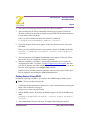
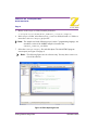
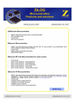
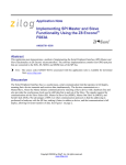
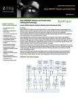
Z8 Encore! XP® Family of
Microcontrollers
Development Kits
QS004303-0205
Quick Start Guide
Introduction
This Quick Start Guide describes how to set up your Z8 Encore! XP® Development Kit
and start using it to build designs and applications.
Kit Contents
Hardware
• One of the following:
– Z8 Encore! XP® 4K Series Development Board
– Z8 Encore! XP® 4K Series 8-Pin Development Board
– Z8 Encore! XP® F08xA Series Development Board
• Smart Cable for PC to Z8 Encore!® Development Board (DB9 to six-pin male)
• (Z8F04A08100KIT development kits only) USB Smart Cable for PC to Z8 Encore!®
Development Board and driver CD-ROM
• Universal 5V power supply
Software (on CD-ROM)
• ZDS II–Z8 Encore!® IDE with ANSI C-Compiler
• Sample code
• Acrobat Reader install program
• Document browser
Documentation
• Registration Card
• Z8 Encore! technical documentation (on CD-ROM)
– Development Kit User Manual
– ZDS II–IDE User Manual
– eZ8 CPU User Manual
– Product Specification
ZiLOG Worldwide Headquarters • 532 Race Street • San Jose, CA 95126
Telephone: 408.558.8500 • Fax: 408.558.8300 • www.zilog.com
Z8 Encore! XP® Development Kits
Quick Start Guide
Page 2
–
–
–
–
Product Brief
Application notes
Flyers
Product Line Card
Requirements
Table 1 lists the system requirements for running ZDS II.
Table 1. ZDS II System Requirements
Recommended Configuration
Minimum Configuration
• PC running MS Windows XP Professional,
SP1
• Pentium III/500 MHz or higher processor
• 128 MB RAM
• 110 MB hard disk space
• Super VGA video adapter
• CD-ROM drive
• Ethernet port
• One or more RS-232 communications ports
• PC running MS Windows 98SE/WinNT 4.0–
SP6/Win2000–SP3/WinXP Professional–SP1
• Pentium II/233 MHz processor
• 96 MB RAM
• 25 MB hard disk space (documentation not
installed)
• Super VGA video adapter
• CD-ROM drive
• Ethernet port
• One or more RS-232 communications ports
Setting up the Development Board
The PC communicates with the Z8 Encore! development board using the serial port of the
PC or, in the case of the Z8F04A08100KIT kit, the USB port of the PC. The Z8 Encore!
serial Smart Cable and USB Smart Cable convert the RS-232 signals into the 3.3V bidirectional open-drain signal needed to communicate with the on-chip debugger.
Caution: Always use a grounding strap to prevent damage resulting from electrostatic discharge (ESD).
1. For initial setup, make sure jumper JP4, DIS IRDA, is IN (shunt installed). See the
appropriate Z8 Encore! XP® Development Kit User Manual (UM0166 for the XP 4K
Series kit, UM0187 for the XP 4K Series Z8F04A08100KIT kit, UM0186 for the XP
F08xA Series kit) for detailed jumper descriptions.
2. For the Z8F04A08100KIT XP 4K Series 8-pin kit only. To run the Z8F04A08100KIT
in demo mode, ensure the jumpers are set as follows: J3 1-2, J4 OUT, J5 1-2, J6 1-2,
J7 OUT, J8 1-2, J9 1-2, J10 1-2, J11 OUT. For complete details on jumper settings for
Requirements
QS004303-0205
Z8 Encore! XP® Development Kits
Quick Start Guide
Page 3
this kit, refer to the Z8F04A08100KIT Z8 Encore! XP™ 4K Series User Manual,
UM0187.
Note: Steps 3 and 4 below refer to installing the serial Z8 Encore! Smart Cable. For
instructions on installing the Z8 Encore! USB Smart Cable, refer to the USB
Smart Cable User Manual, UM0181, on the CD-ROM included with the
development kit.
Caution: Do not connect the power supply to the development board before connecting a Z8 Encore! Smart Cable to both the host PC and development
board.
3. Connect the serial port of the PC to the Z8 Encore! Smart Cable DB-9 female connector.
4. Connect the Z8 Encore! Smart Cable to development board pin header P2.
5. Connect the power supply to the development board at J1, then to an electrical outlet
(Figure 1 on page 4).
Connecting the Power Supply
The universal power supply kit features four different plug adapters in one box and the
power supply itself in another. The power supply ships with a slide-out plate that must be
removed to insert the location-specific plug adapter.
1. Remove the slide-out plate.
2. Select the AC plug adapter appropriate for your locale and insert it into the slot that
remains after removing the slide-out plate.
3. Slide the new plug adapter into the slot until it snaps into place.
4. Plug the power supply into an electrical outlet.
QS004303-0205
Setting up the Development Board
Z8 Encore! XP® Development Kits
Quick Start Guide
Page 4
Serial
Smart
Cable
Serial Port
Host PC
To Electrical
Outlet
P2
Adapter
Slot
Development
Board
AC Cord
Receptacle
J1
Universal
Power Supply
Figure 1. Development Board External Connections
(Serial Z8 Encore! Smart Cable shown)
For convenience, you can leave the adapter slot cover in place and plug in a standard computer equipment AC power cord (purchased separately) between the AC cord receptacle
on the end of the power supply and an electrical outlet.
Installing the ZDS II–Z8 Encore!® Software
Perform the following steps to install the software tools:
1. Load the ZDS II CD into the CD-ROM drive of the host PC. The CD launches
DemoShield automatically and provides a menu to install the product and
documentation.
2. Select INSTALL PRODUCTS, and then INSTALL ZDS II to display the Installation
Wizard.
3. Click Next to continue with the installation. The License Agreement appears.
Installing the ZDS II–Z8 Encore!® Software
QS004303-0205
Z8 Encore! XP® Development Kits
Quick Start Guide
Page 5
4. Select Yes to accept the agreement and proceed with the installation.
5. After selecting Yes, the Choose Destination Location screen appears. Follow the
directions on the screen and choose whether to install ZDS II in the default location or
in some other folder. Click Next.
Unless you select a different location, the software is installed in:
C:\Program Files\ZiLOG\ZDSII_Z8Encore_<version>\
6. The Select Program folder screen appears. Follow the directions on the screen and
click Next.
Unless you select a different location, the program is located in the Start menu under
Programs → ZiLOG ZDS II Z8 Encore! <version> ZDS II Z8 Encore!
<version>
7. After selecting Next, the Register Your Software screen appears. Follow the instructions on the screen to complete the software registration.
8. When the installation is complete, a screen appears reminding you to register the
development kit online. To register, visit http://support.zilog.com/support/ and enter
your ZiLOG Support user name and password, or select Create Account if you do not
have one. After logging in, select Register New Products.
Registered users can submit technical questions online and check status of their questions by logging in and clicking the Support Requests menu.
Getting Started Using ZDS II
Perform the following procedure to open and use the ledBlink.zdsproj sample project.
Note: These procedures reference the
1. Connect the development board to the host PC’s serial communications port using the
Smart Cable, as described on page 2.
2. Apply power to the development board.
3. Run the ZDS II software. By default, the ZDS II program is located in the Start menu
under:
Programs → ZiLOG ZDS II Z8 Encore! <version> → ZDS II Z8 Encore!
<version>
4. Select Open Project from the File menu. The Open Project dialog box appears.
QS004303-0205
Getting Started Using ZDS II
Z8 Encore! XP® Development Kits
Quick Start Guide
Page 6
5. Browse to the Samples folder, located by default in:
c:\Program Files\ZiLOG\ZDSII_Z8Encore_<version>\Samples\
6. In the Samples folder, select the Z8Fxxxx_ledBlink folder, then the src folder, to
access the ledBlink.zdsproj project file.
Note: The sample used in the following steps is in the C programming language. An
assembler version of the ledBlink sample is located in the
Z8Fxxxx_ledBlink_asm folder.
7. Select the ledblink.zdsproj file and click Open. The initial ZDS II program
screen opens (see Figure 2 on page 6).
Note: The following figures are for reference only. You may have a newer version of the software.
Figure 2. ZDS II Opening Screen
Getting Started Using ZDS II
QS004303-0205
Z8 Encore! XP® Development Kits
Quick Start Guide
Page 7
8. Click the Rebuild All icon to build the project. Wait for the build to
complete.
9. Click the Reset icon to connect and download the code to the
development board.
10. Click Go to start the program. The screen changes as illustrated in
Figure 3 on page 7.
Rebuild
All Icon
Reset
Icon
Go
Icon
Figure 3. ZDS II Active Screen
QS004303-0205
Getting Started Using ZDS II
Z8 Encore! XP® Development Kits
Quick Start Guide
Page 8
11. The three LEDs on the development board begin blinking in sequence. If the LEDs do
not blink, start over from Step 3 on page 5.
Note: (Z8F04A08100KIT development kits only) LED D2/PA0 is shared with the
DBG pin when the board is in debug mode. The LED will therefore not be
fully illuminated.
12. Press the TEST pushbutton to change the sequence of the LEDs to blink in the opposite direction.
For more information about using ZDS II and building projects for your Z8 Encore!®
development kit, refer to the ZiLOG Developer Studio II–Z8 Encore!® User Manual
(UM0130).
Getting Started Using ZDS II
QS004303-0205
Z8 Encore! XP® Development Kits
Quick Start Guide
Page 9
This publication is subject to replacement by a later edition. To determine whether a later
edition exists, or to request copies of publications, contact:
ZiLOG Worldwide Headquarters
532 Race Street
San Jose, CA 95126
Telephone: 408.558.8500
Fax: 408.558.8300
www.ZiLOG.com
Document Disclaimer
ZiLOG is a registered trademark of ZiLOG Inc. in the United States and in other countries. All
other products and/or service names mentioned herein may be trademarks of the companies with
which they are associated.
©2005 by ZiLOG, Inc. All rights reserved. Information in this publication concerning the devices,
applications, or technology described is intended to suggest possible uses and may be superseded.
ZiLOG, INC. DOES NOT ASSUME LIABILITY FOR OR PROVIDE A REPRESENTATION OF
ACCURACY OF THE INFORMATION, DEVICES, OR TECHNOLOGY DESCRIBED IN THIS
DOCUMENT. ZiLOG ALSO DOES NOT ASSUME LIABILITY FOR INTELLECTUAL PROPERTY INFRINGEMENT RELATED IN ANY MANNER TO USE OF INFORMATION,
DEVICES, OR TECHNOLOGY DESCRIBED HEREIN OR OTHERWISE. Devices sold by
ZiLOG, Inc. are covered by warranty and limitation of liability provisions appearing in the ZiLOG,
Inc. Terms and Conditions of Sale. ZiLOG, Inc. makes no warranty of merchantability or fitness for
any purpose Except with the express written approval of ZiLOG, use of information, devices, or
technology as critical components of life support systems is not authorized. No licenses are conveyed, implicitly or otherwise, by this document under any intellectual property rights.
QS004303-0205