1
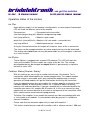
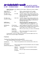
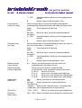
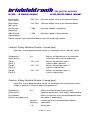
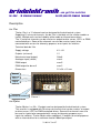
brixlelektronik
bc-12er – 12 channel receiver
...we got the solution
bc-20 plus 20 channel receiver
Description
bc-12er
The bc-12er is a 12 channel receiver designed for the brixlcontrol system.
Supplying 12 universal channels, the bc-12er is the ideal unit for smaller models or
trailers. Multiple units can be linked by either cable or infrared connections.
The 12 universal channels can be used as an output to drive servos, LED´s or PWM
controlled drivers. Some of the channels can also be used as inputs to be
connected with sensors for telemetry purposes or as inputs for switches.
Technical data bc-12er
Supply voltage
4V – 8V
Outputs (universal)
12
Maxmimum load (output)
20mA
Analogue input (switch)
max 4
PWM output
max 5
PWM output for bc-msII
max 2
Dimensions
22 x 34 x 12 mm
Ground Plus +
1
12
1
Signal
Connector for antenna
Picture 1
bc-20plus
The bc-20 plus is a 20 + 12 output receiver designed for the brixlcontrol system.
This receiver is equipped with 20 universal channels that can be used as an output
to drive servos, LED´s or PWM controlled drivers. Some of the channels can also
be used as inputs to be connected with sensor for telemetry purposes or as
inputs for switches. The bc-20 plus offers additional 12 outputs for on/off purposes
with an internal driver for a maximum load of 100mA per output.
23.06.14 Vxx417
brixlelektronik
bc-12er – 12 channel receiver
...we got the solution
bc-20 plus 20 channel receiver
Technical data bc-20 plus
Supply voltage
Please refer to the remarks at the
end of this document for information
Outputs (universal)
20
Outputs on/off
12
Maxmimum load (universal output)
20mA
Analogue input (switch)
max 4
PWM output
max 5
PWM output for bc-msII
max 2
Dimensions
30 x 60 mm
20 universal outputs
1
20
Ground -
Plus +
Plus +
Connector for antenna
Ground Connector for
infrared LED
Picture 2
12 on/off outputs max.100mA
load per output
23.06.14 Vxx417
brixlelektronik
bc-12er – 12 channel receiver
...we got the solution
bc-20 plus 20 channel receiver
Please read and follow the hints and remarks on the last pages
of this manual concerning mounting and power supply!
Functionality of outputs
Some of the universal outputs can be configured during the programming process
as PWM outputs or inputs for sensors etc. Please refer to the shematics below for
further details.
bc-12er
------------------------------------------------------| (G) (G) (G) (G) (G) (G) (G) (G) (G) (G) (G) (G)
|
| (V) (V) (V) (V) (V) (V) (V) (V) (V) (V) (V) (V)
|
| (S1)(S2)(S3)(S4)(S5)(S6)(S7)(S8)(S9)(S10)(S11)(S12) |
| P
P
P
P
P
MP M
M
M
DI
|
|
()|
| (O) ( )
()|
| (I) ( )
()|
| (V) (V)
()|
| (G) (G)
()|
-------------------------------------------------------
bc-20 plus
--------------------------------------------------------------------------------------------------|(G) (G) (G) (G) (G) (G) (G) (G) (G) (G) (G) (G) (G) (G) (G) (G) (G) (G) (G) (G) (G)
|
|(G) (V) (V) (V) (V) (V) (V) (V) (V) (V) (V) (V) (V) (V) (V) (V) (V) (V) (V) (V) (V)
|
|(V+) (S1)(S2)(S3)(S4)(S5)(S6)(S7)(S8)(S9)(S10)(S11)(S12)(S13)(S14)(S15)(S16)(S17)(S18)(S19)(S20) |
|(V+) M
M M MP P P P
P P
DI
P
PN
PN
N
N
N
N |
|
|
|
Led3
|
|
|
|
Led2
|
| (O)
Led1
|
| (I)
|
| (V)(V+) (V+) (V+) (V+) (V+) (V+) (V+)
(V+) (V+) (V+) (V+) (V+) (V+) |
| (G)(IR) (S21)(S22)(S23)(S24)(S25)(S26)
()()()()() (S27)(S28)(S29)(S30)(S31)(S32) |
---------------------------------------------------------------------------------------------------
G = GND
V = +5V (BEC)
V+ = Power supply for bc-20 plus (7,0 – 14V)
Sx = Universal output
M = Measuring input
P = PWM output
23.06.14 Vxx417
brixlelektronik
bc-12er – 12 channel receiver
...we got the solution
bc-20 plus 20 channel receiver
IR = IR LED connector with integrated resistor
I = IR sender or receiver
D = Display
N = Multiswitch/Nautic Module
LED1 = Status LED
LED2 = Eeprom/Memory access
LED3 = Operation indicator
Installation
The modules must be connected with an antenna and must be supplied with the
supply voltage in the assigned range. Please refer to picture 1 and 2 for the correct
connection.
(Remark: the coded wire of the antenna must face outwards)
The antenna code must have been programmed in the transmitter as per the
instructions in the transmitter manual. Switch on the transmitter and the receiver
and connect them as per the manual. Once the connection is established the blue
LED on the tranmitter will light up and you can start programming the reciver.
Remarks
The texts and terms in the programming menues are german and can not be
translated by now. This manual will use the german terms as they appear in the
menues. The english translation willl appear in [brackets].
The term input device is used in the text for all devices on the transmitter that can
be used to control the model. Upon delivery the transmitter might be equipped with
different devices which can be individually configured. The standard configuration
contains sticks, 3 position switches, 3 position momentary switches and rotating
pots. An input device can be also connected to the receiver and act similar to the
input devices on the transmitter.
The term output device is used for all actors in the model which are connected to
the receiver. An output device can be a servo, ESC,PWM driver or an LED.
23.06.14 Vxx417
brixlelektronik
bc-12er – 12 channel receiver
...we got the solution
bc-20 plus 20 channel receiver
Operation status of the module
bc-12er
Upon delivery output 1 on the module is configured as a status output. A connected
LED will show the different states of the module.
Permanent on
= Connected to the transmitter
slow flash(long on/long off)= Module in programming mode
flash (long off/flash)
= Module in park mode
quick flash (short off/flash) = Module in fail safe mode – connection lost
very long off/flash
= Module powered up – check ok
Using the infrared connection this output will show the status of the ir-connection.
The status can be reprogrammed on any other output and can also be eliminated.
The settings described below can only be performed if any of the outputs is defined
as a status out put.
bc-20 plus
The bc-20 plus is equipped with a green LED onboard. This LED will show the
status of the module.The flash codes are similar to the bc-12er. The settings
described below can be changed on output 33 wich is permanently assigned to
the built in status LED.
Funktion: Status [Feature: Status]
With this feature you can assign a number to the the bc-12er module. This is
required for cable linked modules for remote programming. This module number
must be unique in one model and is only required for programming. In normal
operation all linked modules will get the information sent out by the transmitter.
If you are operating more than one module this number must be assigned to each
individual module. 0 should not be used as this is a general adress to access
modules with unknown identifier. If you got a module with an unknown identifier the
tranmitter can access this module with the adress 0. In this case connect just one
module with an unnown identifier to an antenna and connect to the transmitter. With
0 this module can be accessed and reprogrammed.
To link bc-12er modules in one model the antenna must be connected parallel with
a 4 wire cable to all modules. A y-connection cable (bc-ypsylon) is available to
connect 2 modules.
Please note that the telemetric option will just work with module 1 !
This feature should only be used with tranmitters with a software version 1.500 and
23.06.14 Vxx417
brixlelektronik
bc-12er – 12 channel receiver
...we got the solution
bc-20 plus 20 channel receiver
higher. Transmitters with software versions below 1.500 can only access modules
with identifier 0!
Moduladresse
[Module identifier]
0..9
Define a unique identifier for this module
Upon delivery all modules will come with 0
Min.Spannung
[minimum voltage]
3.5..9.99
The BEC voltage will be monitored and this will
define the minimum voltage. A voltage below the
programmed value will trigger the alarm on the
transmitter (bc-12er)
Min.Spannung
[minimum voltage]
5.00..15.0
The BEC voltage will be monitored and this will
define the minimum voltage. A voltage below the
programmed value will trigger the alarm on the
transmitter (bc-20 plus)
BSZ EIN mit
[hour meter on]
A..z
The hour meter will be started with this input
device while signal is <-10% and > 10%.
`-` (below A) will reset the resetable hour meter
BEC/Wandler
[BEC]
Ein bei Verb.
[on if connected]
With this option the internal BEC system on the
bc-20 plus will be switched off when the module is
in park mode (saves energy while in park)
Immer Ein
[Always on]
BEC will remain always on. (Servos will hold load)
Aus b.LoBat
[Off if battery low]
BEC will be disabled if the programmed min
voltage is reached
A second BEC system will supply the main processor on the module even if the
BEC for the universal output is switched off.
Features
Funktion:Servo/Regler [Function:Servo/ESC]
Stick movement will be transmitted 1:1 from transmitter to receiver
Senderkanal
A-z
Defines the input device of the tranmitter (Stick, switch, etc)
[Input device]
Einschaltwert
[Default value power on]
Defines the position of the connected device when the module
is powered up.
Gemerkt
[Memory]
Last position of the connected device before
switched off
kein Sig.
No servo signal send to the connected device
[no signal]
23.06.14 Vxx417
brixlelektronik
bc-12er – 12 channel receiver
Ausschaltwert
[switch off value]
Funkabrisswert
[fail safe]
Wie begrenzen
[limtation of signal]
...we got the solution
bc-20 plus 20 channel receiver
+/- 125%
Connected device will set to the programmed
position
0
Neutral signal will be provided (1.5ms)
Defines the position of the connected device during park
mode (choosing and connecting to new model with transmitter)
halten
[hold]
Current position will be held
kein Sig.
[no signal]
No servo signal send to the connected device
+/- 125%
Connected device will be set to the programmed
position
0
Neutral signal will be provided (1.5ms)
Defines the position of the connected device when the signal is
lost or the transmitter is switched off
halten
[hold]
Current position will be held
kein Sig.
[no signal]
No servo signal send to the connected device
+/- 125%
Connected device will be set to the programmed
position
0
Neutral signal will be provided (1.5ms)
ohne
[without]
Feature disabled
Endschalter Pos +-100
[limit switch]
This output will be set to neutral from
this positive value and higher
Neg +-100
This output will be set to neutral from
this negative value and below
50%Endsch +100
Just -100%..0% can be used
-100
Just 0%..100% can be used
0
-100%..+100& can be used
(to be used for limit switches)
+100%
+100
-100%..+100% can be used
0
-100%..0% can be used
-50
-100%..-50% can be used
-100%
+50
0
-100
23.06.14 Vxx417
+50%..+100% can be used
0..+100% can be used
-100%..+100% can be used
brixlelektronik
bc-12er – 12 channel receiver
...we got the solution
bc-20 plus 20 channel receiver
AUS % AUS 0..125%
Using a potentiomer this can be used
to switch of this output at a certain
angle of the pot
Tempomat This will enable a cruise control option.
[Cruise control]
Choose an input device (momentary switch recommended) with „Begrenzung mit“ that
can control this feature. This feature will work similar to a „real“ car cruise control. Using
the switch with the throttle stick in any other position than 0 will store this position and you
can release the throttle. The model will hold speed until you either clear the cruise control
with the switch in opposite direction or with the throttle stick in a position higher than the
stored one. Cruise control will be also stoped when moving the throttle stick in reverse
direction. Using the switch with the model in stop and the throttle stick in neutral the
porgrammed throttle position will be used and the model will run with the previously stored
speed.
Begrenzung mit
[limitation with]
A-z
Defines the input device that controls the limitation
(input devices connected to the bc-12er can also control
the limitation]
Ebeneschalter
[Level control]
A-z
Defines the input device on the transmitter that
enables/controls the different levels
Ebenenestellung
[Level assignment]
Defines on which level this output will work
(use 3 position switch for proper control of the levels)
E+ 0+ A+
works on all levels
E- 0- A+
works just in the upper level(switch up)
E- 0+ Aworks just in the mid level(sw. Mid position)
E+ 0- Aworks just in the lower level (switch down)
Gegenläufig
[Reverse]
Nein
Normal movement of connected device
[no]
Ja/Invers
Reverse movement of connected device
[Yes/Reverse]
..+SigAus
Signal will be switched of after 10 sec downtime
[..Signal off] (no change of position of input device)
Offset/Trim
-125%..+125%
Blindzone
[Dead zone]
-95%..+95% Defines the dead zone around the neutral position.
Expo wann
[Expo. Start at]
5..95%
Defines the turning point of the exponential curve
Expo wie viel
[Expo value]
5..95%
Defines the value at the turning point. E.g.
Expo wann 10% and Expo wie viel 50% cause a
10% movement of the connected device at 50% of
Defines the offset of the connected device
23.06.14 Vxx417
brixlelektronik
bc-12er – 12 channel receiver
...we got the solution
bc-20 plus 20 channel receiver
the stick movement
MultiplikatorP
[Multiplier positive]
0.2..2.00
Stick movement multiplied with MultiplikatorP is
movement of the connected device(positive)
MultiplikatorM
[MultiplierM]
0.2..2.00
Stick movement multiplied with MultiplikatorM is
movement of the connected device(negative)
Maximalwert
[max. value]
-100..125% Maximum output value for the conncted device
Minimalwert
[Min.value]
-125..100%
Minimum output value for the conncted device
Schnelligkeit
[Speed]
0.01..100
Maximum speed of the signal change for the
connected device. Controls servo/esc speed.
Übersteuern
[overdrive]
A-z
Defines the input device for the overdrive option
Überst.Multi
[overide multiplier]
-100..+100% Defines the % of the overide option. The overide
can be used in + or – direction and is defined as 0
when the module is powered up.
AusgangsSignal
[Output signal]
Puls
PWM1
PWM2
Default setting for servos and esc
A 0-100% PWM signal will be provided on this
output (to be used with bc-msII)
-100%..+100% PWM signal will be provide on this
output (to be used with bc-msII)
Choosing PWM2 will also release the feature „PWM Erweitert“ [PWM extended] which will
only be uesd on the bc-msII. Please refer to the manual of the bc-msII for further details.
Funktion: Hydraulik [Feature: Hydraulic]
This feature will provide a hydraulic simulation with standard servos. The connected
device (servo) will only move as long as the coresponding input device is moved.
The connected device will stop when the input device is in neutral.
Senderkanal
[Input device]
A-z
Einschaltwert
[Default value power on]
Defines the input device of the tranmitter (Stick, switch, etc)
Defines the position of the connected device when the module
is powered up.
Gemerkt
[Memory]
Last position of the connected device before
switched off
kein Sig.
[no signal]
No servo signal send to the connected device
23.06.14 Vxx417
brixlelektronik
bc-12er – 12 channel receiver
Ausschaltwert
[switch off value]
Funkabrisswert
[fail safe]
Ebenenschalter
[Level control]
Ebenenestellung
[Level assignment]
...we got the solution
bc-20 plus 20 channel receiver
+/- 125%
Connected device will be set to the programmed
position
0
Neutral signal will be provided (1.5ms)
Defines the position of the connected device during park
mode(choosing and connecting to new model with transmitter)
halten
[hold]
Current position will be held
kein Sig.
[no signal]
No servo signal send to the connected device
+/- 125%
Connected device will be set to the programmed
position
0
Neutral signal will be provided (1.5ms)
Defines the position of the connected device when the signal is
lost or the transmitter is switched off
halten
[hold]
Current position will be held
kein Sig.
[no signal]
No servo signal send to the connected device
+/- 125%
Connected device will be set to the programmed
position
0
Neutral signal will be provided (1.5ms)
A-z
Defines the input device on the transmitter that
enabled/controls the different levels
Defines on which level this output will work
(use 3 position switch for proper control of the levels)
E+ 0+ A+
works on all levels
E- 0- A+
works just in the upper level(switch up)
E- 0+ Aworks just in the mid level(sw. Mid position)
E+ 0- Aworks just in the lower level (switch down)
Gegenläufig
[Reverse]
Nein
Normal movement of connected device
[no]
Ja/Invers
Reverse movement of connected device
[Yes/Reverse]
..+SigAus
Signal will be switched of after 10 sec downtime
[..Signal off] (no change of position of input device)
Offset/Trim
-125%..+125%
Blindzone
[Dead zone]
-95%..+95% Defines the dead zone around the neutral position.
Defines the offest of the connected device
23.06.14 Vxx417
brixlelektronik
bc-12er – 12 channel receiver
...we got the solution
bc-20 plus 20 channel receiver
Maximalwert
[max. value]
-100..125% Maximum output value for the conncted device
Minimalwert
[Min.value]
-125..100%
Minimum output value for the conncted device
Auf.Geschw.
[Speed up]
1..200
Maximum speed in up direction
Abw.Geschw.
[Speed down]
1..200
Maximum speed in down direction
Please note that some connected devices may not accept high speeds.
Funktion: 3Gang Getriebe [Feature: 3 speed gear]
3 positions can be programmed to control a 3 speed gear with a 3 position switch
Senderkanal
[Input device]
A-z
Defines the input device of the tranmitter
(3 Position switch recommeded here)
Gang1
[Gear 1]
-125..+125
Defines the position in gear 1
(switch in down position)
Gang2
[Gear 2]
-125..+125
Defines the position in gear 2
(switch in mid position)
Gang3
[Gear 3]
-125..+125
Defines the position in gear 3
(switch in up position)
Funktion: 6Gang Getriebe [Feature: 6 speed gear]
6 positions can be programmed to control a 6 speed gear with a momentary switch.
Usage is sequential (similar to motorcycle gearboxes)
Senderkanal
[Input device]
A-z
Einschaltwert
[Default value power on]
Defines the input device of the tranmitter
3 position momentary switch highly recommended
Defines the position of the connected device when
the module is powered up.
Gemerkt
[Memory]
Last position of the connected device before
switched off
1..6
Set position
23.06.14 Vxx417
brixlelektronik
bc-12er – 12 channel receiver
bc-20 plus 20 channel receiver
Ausschaltwert
Defines the position of the connected device
in park mode
Current position will be held
halten
[hold]
1..6
Funkabrisswert
[Fail safe]
G.Position 1..6
[Gear position]
...we got the solution
Set position
Defines the position of the connected device when the
signal is lost or the transmitter is switched off
halten
[hold]
1..6
Current position will be held
-125..+125
Defines the 6 available positions for the connected
device
Set position
Funktion: 6Gang erweitert [Feature: 6 speed gear extended]
This feature can be linked to the previous feature to add an additional output
device. e.g. 2 servos can control one 6 speed gearbox.
Bezugskanal
1..12
6 speed gear is on out put 1..12.
[linked, origin channel for the 6 speed gear]
G.Position 1..6
[Gear position]
-125..+125
Defines the 6 available positions for the linked
connected device
Funktion: Raupe Links [Feature: Track mixer left]
With this feature you can control tracked models or models with one motor per side
like a standard model. This is the feature for excavaors or dozer to be controled in
the same way as you are used to control your truck. One stick controls
forward/backward and one stick controls the direction.
Gaskanal A..z:a..z
[motor control]
Defines the input device of the tranmitter (Stick, switch, etc)
for the forward/backward movement
Einschaltwert
[Default value power on]
Defines the position of the connected device when the module
is powered up.
Gemerkt
[Memory]
Last position of the connected device before
switched off
kein Sig.
No servo signal send to the connected device
[no signal]
+/- 125%
Connected device will be set to the programmed
position
23.06.14 Vxx417
brixlelektronik
bc-12er – 12 channel receiver
...we got the solution
bc-20 plus 20 channel receiver
0
Neutral signal will be provided (1.5ms)
Ausschaltwert
Defines the position of the connected device during park mode
[switch off value]
(choosing and connecting to new model with transmitter)
Funkabrisswert
[fail safe]
halten
[hold]
Current position will be held
kein Sig.
[no signal]
No servo signal send to the connected device
+/- 125%
Connected device will be set to the programmed
position
0
Neutral signal will be provided (1.5ms)
Defines the position of the connected device when the signal is
lost or the transmitter is switched off
halten
[hold]
Current position will be held
kein Sig.
[no signal]
No servo signal send to the connected device
+/- 125%
Connected device will be set to the programmed
position
0
Neutral signal will be provided (1.5ms)
Lenkkanal
[direction]
A..z
Defines the input device of the transmitter (Stick,
switch, etc) for the direction control
Lenkung Zugabe
[steering increase]
-100..+100
defines the increase of speed of the outer track
Lenkung Abnahme
[steering decrease]
-100..+100
defines the decrease of speed of the inner track
Ebeneschalter
[Level control]
A-z
Ebenenestellung
[Level assignment]
Gegenläufig
[Reverse]
Defines the input device on the transmitter that
enabled/controls the different levels
Defines on which level this output will work
(use 3 position switch for proper control of the levels)
E+ 0+ A+
works on all levels
E- 0- A+
works just in the upper level(switch up)
E- 0+ Aworks just in the mid level(sw. Mid position)
E+ 0- Aworks just in the lower level (switch down)
Nein
Normal movement of connected device
[no]
Ja/Invers
Ireverse movement of connected device
[Yes/Reverse]
..+SigAus
Signal will be switched of after 10 sec downtime
23.06.14 Vxx417
brixlelektronik
bc-12er – 12 channel receiver
...we got the solution
bc-20 plus 20 channel receiver
[..Signal off]
Offset li
[offset left]
-125%..+125%
Defines the offset of the connected device on the
right side
Offset re
[offset left]
-125%..+125%
Defines the offset of the connected device on the
right side
Multip. li
[Multiplier left]
0.2..2.00
Stick movement multiplied with Multip.li is
movement of the connected device on the left side
Multip. re
[Multiplier right]
side
0.2..2.00
Stick movement multiplied with Multip.re is
movement of the connected device on the right
Maximalwert
[max. value]
-100..125%
Maximum output value for the conncted device
Minimalwert
[Min.value]
-125..100%
Minimum output value for the conncted device
Schnelligkeit
[Speed]
0.01..100
Maximum speed of the signal change for the
connected device. Controls servo/esc speed.
Funktion: Raupe rechts [Feature: Track mixer right]
With this feature the second output for the track mixer will be defined
Raupe links ist
[Track mixer left]
Gegenläufig
[Reverse]
1..12
Track mixer left is defined on output ?
Nein
Normal movement of connected device
[no]
Ja/Invers
Reverse movement of connected device
[Yes/Reverse]
..+SigAus
Signal will be switched of after 10 sec downtime
[..Signal off] (no change of position of input device)
Funktion: Nautic/Multiswitch [Feature: Nautic/Multiswitch]
Nautic or multiswitch modules compatible to the Robbe®/Futaba® standard can be
controlled with this feature. (like GEWU® GMS16R, Beier Soundmodule, Wedico®)
GEWU®
Switch 1 A(up)
= Exit 1
Switch 1 E(down)
= Exit 2
Switch 2 A(up)
= Exit 3
23.06.14 Vxx417
brixlelektronik
bc-12er – 12 channel receiver
Switch 2 E(down)
...we got the solution
bc-20 plus 20 channel receiver
= Exit 4
USM-RC-2 Beier Soundmodule (please note sequence of the switches)
Switch 1 A(up)
= Switch 8 up
Switch 1 E(down)
= Switch 8 down
Switch 2 A(up)
= Switch 7 up
Switch 2 E(down)
= Switch 7 down.....
Schalter 1..8
[Switch]
A..z
Which input device shall be used „-“ deactivated
Ebenenschalter
[Level control]
A..z
Defines the input device on the transmitter that
enables/controls the different levels
Ebenenestellung
[Level assignment]
Defines on which level this output will work
(use 3 position switch for proper control of the levels)
E+ 0+ A+
works on all levels
E- 0- A+
works just in the upper level(switch up)
E- 0+ Aworks just in the mid level(sw. Mid position)
E+ 0- Aworks just in the lower level (switch down)
Funktion: Licht/LED [Feature: Light/LED]
Senderkanal
[Input device]
A-z
Defines the input device of the tranmitter (Stick, switch, etc)
Einschaltwert
[Default value power on]
Defines the staus of the output when the module
is powered up
Gemerkt
[Memory]
Last status of the connected device before
switched off
Ein
[on]
Output is on (Hi 3.3V)
Aus
[off]
Output is off (Lo 0V)
Ausschaltwert
[switch off value]
Defines the status of the connected device during park
mode
Gemerkt
[Memory]
Last status of the connected device before
switched off
Ein
[on]
Output is on (Hi 3.3V)
Aus
[off]
Output is off (Lo 0V)
23.06.14 Vxx417
brixlelektronik
bc-12er – 12 channel receiver
Funkabrisswert
[fail safe]
Ebeneschalter
[Level control]
Ebenenestellung
[Level assignment]
...we got the solution
bc-20 plus 20 channel receiver
Defines the status of the output device when the signal is
lost or the transmitter is switched off
Gemerkt
[Memory]
Last status of the connected device before
switched off
Ein
[on]
Output is on (Hi 3.3V)
Aus
[off]
Output is off (Lo 0V)
A-z
Defines the input device on the transmitter that
enabled/controls the different levels
Defines on which level this output will work
(use 3 position switch for proper control of the levels)
E+ 0+ A+
works on all levels
E- 0- A+
works just in the upper level(switch up)
E- 0+ Aworks just in the mid level(sw. Mid position)
E+ 0- Aworks just in the lower level (switch down)
Gegenläufig
[Reverse]
Nein
Normal
[no]
Ja/Invers
Feature inverted
[Yes/Reverse]
Ausgabeart
[Definition of switch]
EIN AUS % Defines switching points for on and off if a stick or
pot is used to control this output
Memory Ein Momentary switch moved to EIN (down) toggles
[Memory on] output
Memory Aus Momentary switch moved to AUS (up) toggles
[Memory off] output
EIN 0 AUS
[On 0 Off]
Switch position defines output
SchaltPunkt EIN
[Switching point ON]
-100..+100
Defines stick/pot position for ON(do not use 50%)
Schaltpunkt AUS
[Switching point OFF]
-100..+100
Defines stick/pot position for OFF(do not use 50%)
Bei Stellung AUS
[Switch position up]
Aus/Ein
[on/off]
Defines output in AUS (up) position of switch
Bei Stellung 0
[Switch mid position]
Aus/Ein
[on/off]
Defines output in mid position of switch
Bei Stellung EIN
[Switch position dowen]
Aus/Ein
[on/off]
Defines output in EIN (down) position of switch
23.06.14 Vxx417
brixlelektronik
bc-12er – 12 channel receiver
...we got the solution
bc-20 plus 20 channel receiver
EIN Zeit/Nachlauf
[On time]
Used with AUS/Zeit for flash options.
If AUS Zeit/Pause is defined this option will set the
on-time of the output. If AUS/Zeit is set to 0 this
value will define the time the output will remain on
after the input device is set to off.
To simulate a double or triple flash (emergency
vehicles) choose either 2Blitz or 3Blitz. These
options will appear if values below 0 will be
chosen. The time between the double or triple f
lash will be defined with AUS/Zeit.
AUS Zeit/Pause
[Off time/Pause]
Defines the OFF time in between flashes. 0 is
permanent on.
Funktion: Blinker Links [Feature: Indicator Left]
This feature defines the settings for the output of an indicaor on the left side
Senderkanal
[Input device]
A-z
Einschaltwert
[Default value power on]
Defines the input device of the tranmitter (Stick, switch,
etc.)
Defines the status of the output when the module is
powered up
Warnbl.
Hazard lights (both indicators on)
[Hazard lights]
Ausschaltwert
[Switch off value]
Links
[Left]
Left indicator on
Rechts
[Right]
Right indicator on
AUS
[Off]
Both indicators off
Defines the status of the output when the module is
in park mode
Warnbl.
Hazard lights (both indicators on)
[Hazard lights]
Funkabrisswert
Links
[Left]
Left indicator on
Rechts
[Right]
Right indicator on
AUS
[Off]
Both indicators off
Defines the status of the output when the connection is
23.06.14 Vxx417
brixlelektronik
bc-12er – 12 channel receiver
[Fail safe value]
...we got the solution
bc-20 plus 20 channel receiver
lost or the transmitter switch off
Warnbl.
Hazard lights (both indicators on)
[Hazard lights]
Links
[Left]
Left indicator on
Rechts
[Right]
Right indicator on
Aus
[Off[]
Both indicators off
Ebenenschalter
[Level control]
Ebenenestellung
[Level assignment]
A-z
Defines the input device on the transmitter that
enabled/controls the different levels
Defines on which level this output will work
(use 3 position switch for proper control of the levels)
E+ 0+ A+
works on all levels
E- 0- A+
works just in the upper level(switch up)
E- 0+ Aworks just in the mid level(sw. Mid position)
E+ 0- Aworks just in the lower level (switch down)
Gegenläufig
[Reverse]
Nein
Normal operation
[no]
Ja/Invers
Reverse option (US indicator style)
[Yes/Reverse]
Lenkkanal(Sender)
[Steering channel]
A..z
Ein Zeit
[On time]
1..500 Defines the on-time of the indicator
Aus Zeit
[Off time]
1..500 Defines the off-time of the indicator
Defines the input device that stops the indicator.
(Steering stick)
Funktion: Blinker Rechts [Feature: Indicator Right]
This feature defines the output for the indicator on the right side
Blink.links ist
1..12 Indicator left is on output? [Reqired to link both
indicators)
Funktion: Eingang Schalter/Signal [Feature: Input Switch/Signal]
A switch or a signal can be fed in the bc-12er. Depending on the voltage/signal on
this input the modules can use this like an input from the transmitter. 0V will create
-125% and voltages higher than 2V will create +125% on the assigned letter. n-z
can be used on the same bc-12er module and n-x will be transmitted also to
23.06.14 Vxx417
brixlelektronik
bc-12er – 12 channel receiver
...we got the solution
bc-20 plus 20 channel receiver
modules wich are linked with infrared.
Please note that input voltages should not be higher than 3.3V. Add a 10k resistor
for protection purposes.
If an open collector output (e.g. brake lights from ESC) is connected to these
inputs, a pull up resistor of 5k to +BEC might be necessary.
Auf Kanal n-z
[Channel n-z]
n..z
Which letter shall be assigned to this input?
Gegenläufig
[Reverse]
NEIN
[No]
0V -125% ..>2V +125%
Ja/Invers
>2V -125% ..0V +125%
[Yes/Reverse]
Funktion: Eingang Poti [Feature: Input Potentiometer]
A potentiometer can be connected to an input using bc-MM-Poti. The position of
the pot will be read and can set any letter from n-z with a value between -125% and
+125%. This letter can be used as an input for functions on the same moduel or can
be transfered to linked module via infrared or cable connection.
The pot value must be between 2.2k and 10k and will be used as a voltage divider.
0V =125% and +3.3V = +125%
Auf Kanal n-z
[Channel n-z]
n..z
Which letter shall be assigned to this input?
Please note:
Letters n-x will be transmitted via infrared to linked modules. Letters y and z will not
be transmitted. This will allow the usage of y and z exclusively on the module where
the coresponding sensor is connected. Please ensure the unique usage of the
letters on linked modules!
Funktion: Eingang Messen [Feature: Measuring Input]
This feature is used for telemetric purposes and will send new measured values
from the receiver to the transmitter every 400ms. Measured values can be also
displayed on the bc-disp on board display. Please note that this feature requires a
restart of the receiver after programming. Otherwise no data will be transmitted.
Messart
Spannung25
[Voltage25]
Voltage measurement using the bc-MM-Sp sensor with
the measurement range of 0..25.0V
Spannung50
[Voltage25]
Voltage measurement using the bc-MM-Sp50 sensor
with the measurement range of 0..50.0V
Strom 10
Current measurement using the bc-MM-St sensor with
23.06.14 Vxx417
brixlelektronik
bc-12er – 12 channel receiver
...we got the solution
bc-20 plus 20 channel receiver
[Current 10]
the measurement range of 0..10A(15A peak). Sensor up
to 50A upon request.
Temp.99
Temperature measurement using the bc-MM-Temp with
the measurment range of 0..99.9°C
Temp.120
Temperature measurement using the bc-MM-Temp with
the measurment range of -20..120°C
Poti
[Pot]
Measurement of a potentiometer connected to a
bc-MM-Poti with the range of -125% to +125%
Druck PY
[Pressure PY]
Measurement of pressure using the bc-MM-Dr-Pisello
sensor with the range of 0.0..34.0bar
Druck PMT
[Pressure PMT]
Measurement of pressure using the bc-MM-Dr-PMT
sensor with the range of 0.0..33.0bar
Druck Damitz
Measurement of pressure using the bc-MM-Dr-Damitz
[Pressure Damitz] sensor with the range of 0.0..35.0bar. This sensor is
designed to be mounted directly on the Damitz valves.
Druck bel
[Pressure brixl]
Measurement of pressure using the
bc-MM-DR-brixlelektronik sensor with the range of
0.0..35 bar. This sensor is equipped with a 3mm thread
for universal connection
Please note that the range of the displayed pressure migh differ from the ranges
printed on the sensors. This is system related and ha no effect on the display
values.
Min.Alarm
0.0-100.0
If the measured value falls below this value an alarm is t
riggered
Max.Alarm
0.0-100.0
If the measured value exceeds this value an alarm is
triggered
An alarm will trigger the red LED on the transmitter and they start flashig. The tactile
alarm (vibration) is triggered 2 times upon the start of an alarm and 1 time when
the alarm condition will dissappear.
Funktion: IR-Sender [Feature: IR-Transmitter]
This fature can be enabled on output 12 on the bc-12er. The bc-20er is equipped
with a dedicated output for an ir led with integrated resistor. All input devices will be
transmitted except y and z.
Funktion: IR-Empfänger [Feature: IR Receiver]
This feature can be enabled on output 12 to connect the bc-ir-emp infrared
receiever.
23.06.14 Vxx417
brixlelektronik
bc-12er – 12 channel receiver
...we got the solution
bc-20 plus 20 channel receiver
Please note that no infrared receiver should be connected during programming. For
programming an antenna or a cable connection must be used.
Funktion: Display [Feature: Display]
A 0.9“ display can be connected to output 12 to visualize different values. It will
display the operating voltage and the values measured by connected sensors.
Senderkanal
[Input device]
A-z
Defines the input device of the tranmitter that will change
the display content. (swap between measuring values
and hour meter). Momentary switch is recommended for
this option.
Screen content measuring values:
brixlcontrol
[status]
[mv1]
[mv2]
[mv3]
[mv4]
Akku:
12.0V (bc-20 plus only]
BEC :
5.04V
[status] can be either:
[Spannung EIN]
[betrieb]
[Empf.konfig]
[Funkabriss]
[geparkt]
Power supply on
Connected to transmitter
Receiver in programming mode
Connection lost, receiver in fail safe mode
Receiver in park mode
[mv1..4]
Measuring values as defined in [Funktion: Eingang Messen] Feature:
Measuring Input
Akku
voltage of power supply
BEC
voltage of BEC
Screen content hour meter:
brixlcontrol
[status]
Vers :
EinZ :
BSZG
BSZ
12417
12
0:27
0:23:15
[status] can be either:
[Spannung EIN]
[betrieb]
Power supply on
Connected to transmitter
23.06.14 Vxx417
brixlelektronik
bc-12er – 12 channel receiver
...we got the solution
bc-20 plus 20 channel receiver
[Empf.konfig]
[Funkabriss]
[geparkt]
Receiver in programming mode
Connection lost, receiver in fail safe mode
Receiver in park mode
Vers
Version number of hard- (12) and software (417)
EinZ
Module has been started xx times
BSZG
Hourmeter total (HH:mm)
BSZ
Hourmeter depending on a defineable input device. (HH:mm:ss)
Input device must be programmed in [Funktion: Status] Feature:
Status. This allows to start and stop the hour meter with the same
input device as a hydraulic pump to monitor operating hours. Hour
meter values will be stored onboard upon status change or every 3
minutes.(resetable)
The flicker effect shown by the display is an intended effect to visualize the
operation.
Funktion: Mischer [Feature: Mixer (only available in bc-20 plus)]
This feature offers up to 6 completely free programmable mixers (M1 to M6). The
mixers can handle up to 8 different input devices.
Ausgang 1-32
[Output 1-32]
M1-M6
Chosse the mixer to be programmed.
MischerFunk
[Mixer function]
Addierer
[Addition]
All input devices will be added and send to Mx
MaxWert
The highest value will be sent to Mx
[Max value]
Mischkanal 1-8
1..8
This input device will be programmed now
[Number of input device for mix function]
Eingangssignal
[Input device]
A..z+M1..M6 This input shall be used. Using M1..M6 will link mixers
Totzone Pos.
0..95
[Dead zone positive]
Input device will not be used up to this value in positive
direction
Totzone Neg.
0..-95
[Dead zone negative]
Input device will not be used up to this value in negative
direction
Multipli.Pos
-200..+200
[Multiplier positive]
Multiplier for positive direction
Multipli.Neg
-200..+200
[Multiplier negative]
Multiplier for negative direction
23.06.14 Vxx417
brixlelektronik
bc-12er – 12 channel receiver
...we got the solution
bc-20 plus 20 channel receiver
23.06.14 Vxx417
brixlelektronik
bc-12er – 12 channel receiver
...we got the solution
bc-20 plus 20 channel receiver
Remarks:
Antenna
Never connect or disconnect the antenna while the receiver is powered up! This
might destroy the modules. The colour coded cable of the antenna is facing away
from the receiver!
Mounting
Depending on the model and the available space for mounting the module can
installed with or without the attached plastic cover. For this purpose we deliver both
parts seperately. If the module is installed without the plastic cover ensure proper
isolation. The module can be fixed in the plastic cover using 2 drops of hot glue.
Module adress
If you are running linked module in a model, ensure a proper assignment of module
numbers. Moule number 1 must be be assigned. This is the only module that can be
used for telemetry purposes. Adress 0 must not be assigned to any of the modules!
Running a single module adress 0 can be used. Moules will be delivered with this
adress.
Modules connected via infrared can not be programmed using this connection. To
program a module which is intended to be used via infrared an antenna must be
connected directly and the module adress must be 0. Once programming is done
the antenna can be removed an the infrad red connection can be used.
If you are using Servonaut or SGS equipment with multiple input lines (motor control
and steering or additional functions) make sure that all inputs of these modules will
be connected to either outputs 1-7, 8-14 or 15-20. Output signals will be send to
these groups of outputs simultaniously and can cause problems when these groups
will be mixed.
Power supply
The bc-20 plus is equipped with a powerful internal BEC system. Do not add
additional BEC systems to this module! The module should not be supplied
from the output side with +5V at any time. Disregard will cause serious
damage to the module!
Power supply for the bc-20 plus is intended to be used with 2s..3s LiPo cellls
(6V..12.6V) or 6..10 NiMh cells (6.0V..14V). Do not use 4s LiFePo4 cells as they
might damage the module due to their higher voltage level!
Linking bc-20 plus modules
If you would like to link multiple bc-20 plus modules please refer to
[email protected] for further information.
23.06.14 Vxx417
brixlelektronik
bc-12er – 12 channel receiver
...we got the solution
bc-20 plus 20 channel receiver
Display/Infrared link
The bc-12 plus supports either a display connected to output 12 or the infrared
connection . If the display is disabled the infrared connection will be enabled
automatically.
Servonaut components with cruise control
If you are running Servonaut speed controllers with cruise control options
(M20+,E20 or similar) we recommend to program a high negative value as fail safe
for the throttle channel to ensure a proper behaviour in the case of a signal loss.
(e.g. -60 to activate the brake funktion)
Within Europe
This product is produced and labeled according to the
Directive 2002/96/EC of the European Parliament and of the Council
of 27 January 2003
on waste electrical and electronic equipment (WEEE)
Please refer to this directive in case of disposal.
23.06.14 Vxx417