1
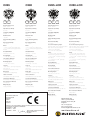
Installation Guide
200 Series
®
Installation guide
200 Series
The 200 Series models utilise C-CAM® bass drivers and a higher spec version of the C-CAM® gold dome tweeter. These models offer higher grade performance, and greater flexibility.
The renowned C-CAM® (Ceramic Coated Aluminium Magnesium alloy) cone maximises the potential of the driver mechanism.
C-CAM® is an innovative alloy material that exhibits ideal mechanical properties for use in high performance loudspeaker
cones and diaphragms.
The pivoting tweeter is based on Monitor Audio’s famous 25mm gold C-CAM® dome. Improvements to the surround and
motor system have extended the frequency response to beyond 30 kHz, so that it is ready to exploit digital cinema and audio
formats.
For the LCR models a unique Inverted Dual Concentric (IDCTM) pivoting mid-range/tweeter module provides up to 18 degrees
of movement, allowing the sound to be directed towards the desired listening zone. These models offer superior performance
and flexibility over typical 2-way or fixed angle speaker designs.
The high frequency level control together with boundary compensation control facilitates a wider range of possible
adjustments. See page 3.
Introduction
Please read this installation guide carefully before proceeding.
NOW AVAILABLE: Pre-construction brackets. These are for use when installing any Custom Installation product before the
plaster board/ rock wall, is fitted. They show the location of the speakers to the builder, allow pre-wiring and give them a solid
secure edge to cut around. Please ask your dealer about these brackets and to confirm which is correct for your installation.
PLEASE CHECK YOU HAVE THE FOLLOWING ITEMS IN THIS KIT BEFORE PROCEEDING:
•
1 x Complete speaker & tweeter assembly.
•
1 x Grille (which can be painted).
•
1 x Mounting cut out template (in packaging).
•
1 x Plastic paint mask (for covering the baffle while painting the frame).
•
1 x Self adhesive grille membrane scrim (to be attached to the inside the grille after it has been painted).
•
1 x Guarantee card in this manual.
Prior to Installation Check the Following:
•
Please check the minimum depth of the product (according to the specifications sheet) is correct for the assembly to
fit into recess.
•
The fixing clamps require a minimum of 25mm (1 Inch) of surface area around the cut-out hole to ensure a secure fixing!
•
Series 200 loudspeakers are splash and moisture proof, so they can be used in bathrooms, pool areas, etc. DO NOT
allow them to be in constant contact with water/ moisture.
•
The fixing clamps will operate on ceilings with a minimum thickness of 9mm (3/8 Inches) to a maximum depth of
32mm (1¼ Inches).
•
Do not attempt to fix these speakers to your ceiling if you are unsure of your ability to provide a secure and safe fixing.
IF IN DOUBT CONTACT YOUR LOCAL AUTHORISED MONITOR AUDIO DEALER.
•
Ensure that there are no water pipes, air ducts or electricity cables running immediately behind the cut out area!
•
Please work from secure steps or scaffold and avoid trailing wires for your safety and those around you.
•
Always turn off the amplifier or other devices in the system when connecting these speakers.
Installation procedures
Painting
NOTE: If you are choosing to paint your In-Ceiling loudspeaker, we recommend you do this prior to installation by following
these simple steps:
1.
Remove the membrane scrim from the inside of the grille (do not fit grille to speaker frame).
2.
Place paint mask over the speaker baffle.
3.
Paint both the frame and the grille at the same time and with the same batch of paint (if they are to be the same colour).
4.
When they are both dry, remove the paint mask from the baffle, and place the spare membrane scrim (in the packaging)
into the inside of the grille.
5.
Your product(s) are now ready to install, including fitting the grille. Please refer to step 4 below.
Using Pre-Construction Brackets
If the holes have been pre-cut, simply refer to step 4 onwards (below) for full fitting instructions.
If pre-construction brackets have been used prior to the fixing of plaster board/ sheet rock and the holes have not been cut,
locate the pre-construction brackets and cut around the inside edge of the bracket. Locate the speaker cable, connect to the
sprung terminals and fit the speaker. Refer to the fitting instructions below (step 4 onwards).
To fine-tune the speakers please refer to the high frequency control and boundary compensation details below
Using the Fixing Template
1.
Use template to locate position of cut out. The adhesive backing allows for repositioning a number of times.
2.
Draw around diameter of the template.
3.
Remove template and cut hole.
4.
Locate speaker cable and connect by pushing the terminals in and releasing to clamp the cables.
5.
Fit back box into prepared hole and tighten fixing clamps. These will move outwards automatically upon tightening!
DO NOT OVER TIGHTEN! Once contact is made 2-3 turns are all that is required.
6.
To fine-tune the speakers please refer to the high frequency control and boundary compensation details below.
High Frequency control
The factory H.F setting provides a flat or 0dB level, which will suit the majority of typical installations.
Setting the switch in the +3dB position will add brightness and additional clarity to the system. This may be effective in a
room with a large amount of soft furnishings.
Setting the switch in the -3dB position will reduce the brightness and provide a duller sound. This may be effective in a room
with a few of soft furnishings, or in an installation with a wooden floor.
Boundary Compensation control
The bass drivers are optimised to work in a large closed cavity, with minimal damping. This should provide a natural roll
off characteristic that will ensure optimum performance and bass extension. However, it may be necessary in certain
installations to locate the speaker close to a corner apex of the ceiling. In this situation the bass region will become
accentuated and un-even, resulting in un-suitable balance characteristics. The effect is similar to placing a conventional hi-fi
speaker in the corner of a room. The boundary compensation provides a gentle roll off character whilst preserving the extreme
low frequency output. The switch position is either in or out.
monitoraudio.co.uk
C265
C-CAM®
C280
C-CAM®
Tri-Grip
MMP®II
C265-LCR
Tri-Grip
C-CAM®
IDC™
C280-LCR
C-CAM®
Tri-Grip
IDC™
Tri-Grip
Frequency Response
60Hz - 30 Hz
Frequency Response
50Hz - 30 Hz
Frequency Response
60 Hz - 30 Hz
Frequency Response
50 Hz - 30 Hz
Impedance (nominal)
6 Ohms
Impedance (nominal)
6 Ohms
Impedance (nominal)
6 Ohms
Impedance (nominal)
6 Ohms
Sensitivity (1W@1M)
88.5dB
Sensitivity (1W@1M)
90dB
Sensitivity (1W@1M)
88.5 dB
Sensitivity (1W@1M)
90 dB
Maximum SPL
108 dBA
Maximum SPL
111.6 dBA
Maximum SPL
108 dBA
Maximum SPL
111.6 dBA
Power Handling (R.M.S)
75 W
Power Handling (R.M.S)
120 W
Power Handling (R.M.S)
85 W
Power Handling (R.M.S)
120 W
Recommended Amp
10 - 75 W
Recommended Amp
15 - 120 W
Recommended Amp
10 - 85 W
Recommended Amp
15 - 120 W
Driver
1 x 6.5” C-CAM®‘cone bass driver
1 x 1” C-CAM® pivoting gold dome
tweeter
Driver
1 x 8” C-CAM® cone bass driver
1 x 1” C-CAM® pivoting gold dome
tweeter
Crossover Frequency/Slope
Bass low pass: 250 Hz @ 6 db/Octave
Mid: 250 Hz @ 6 db/Octave &
3 KHz @ 12 dB/Octave
H.F. 3 KHz @ 12 dB/Octave
Crossover Frequency/Slope
Bass low pass: 250 Hz @ 6 db/Octave
Mid: 250 Hz @ 6 db/Octave &
3 KHz @ 12 dB/Octave
H.F. 3 KHz @ 12 dB/Octave
Overall Diameter
250mm (9 13/16 inch)
Overall Diameter
286mm (11 1/4 inch)
Overall Depth
117 mm (4 10/16 inch)
Overall Depth
124 mm (4 14/16 inch)
Cut-out Hole Diameter
211mm (8 5/16 inch)
Cut-out Hole Diameter
247mm (9 3/4 inch)
Driver
1 x 6.5” C-CAM® cone bass driver
Dual concentric module housing:1 x 4” C-CAM® ‘inverted’ mid-range
driver (IDC )
1 x 1” (25mm) C-CAM® gold alloy
dome tweeter
Driver
1 x 8” C-CAM® cone bass driver
Dual concentric module housing:1 x 4” C-CAM® ‘inverted’ mid-range
driver (IDC )
1 x 1” (25mm) C-CAM® gold alloy
dome tweeter
Mounting Depth
112 mm (4 7/16 inch)
Mounting Depth
119 mm (4 11/16 inch)
Overall Diameter
250 mm (9 13/16 inch)
Overall Diameter
286 mm (11 1/4 inch)
Controls
+3db / 0dB / -3dB High Frequency
level switch &
boundary compensation switch
Controls
+3db / 0dB / -3dB High Frequency
level switch
& boundary compensation switch
Overall Depth
152 mm (6 inch)
Overall Depth
159 mm (6 4/16 inch)
Fixing Type
3 position Tri-Grip dog fixings
Cut-out Hole Diameter
211 mm (8 5/16 inch)
Cut-out Hole Diameter
247 mm (9 3/4 inch)
Fixing Type
3 position Tri-Grip dog fixings
Mounting Depth
147 mm (5 13/16 inch)
Mounting Depth
154 mm (6 1/16 inch)
Cable Connection
Gold plated ‘push’ type terminals
Cable Connection
Gold plated ‘push’ type terminals
Construction Material
Mineral filled ABS plastic (UL-94 VO)
Construction Material
Mineral filled ABS plastic (UL-94 VO)
Controls
+3db / 0dB / -3dB
High Frequency level switch &
Boundary compensation switch
Controls
+3db / 0dB / -3dB
High Frequency level switch &
Boundary compensation switch
Pre-construction Bracket
CB6 (Purple)
Pre-construction Bracket
CB8 (Green)
Fixing Type
3 position Tri-Grip dog fixings
Fixing Type
3 position Tri-Grip dog fixings
Weight Kg (lb)
2.9Kg (6.39 lbs)
Weight Kg (lb)
3.8 Kg (8.38 lbs)
Cable Connection
Gold plated ‘push’ type terminals
Cable Connection
Gold plated ‘push’ type terminals
Construction Material
Mineral filled ABS plastic (UL-94 VO)
Construction Material
Mineral filled ABS plastic (UL-94 VO)
Pre-construction Bracket
CB6 (Purple)
Pre-construction Bracket
CB8 (Green)
Weight Kg (lb)
3.46 Kg (7.7 lbs)
Weight Kg (lb)
4.4 Kg (9.7 lbs)
™
Declaration
Declarat
ion ofof
CoConformity
nfor m ity
We,
We
, MMonitor
on itor Au Audio
dio Ltd.Ltd.
2424Brook
R oad
Brook
Road
Rayleig
h
Rayleigh
Esse
x
Essex
SS6 7XL
SS6 7XL
Eng land
England
a r e
Q u i c k T i m e ™
a n d
d e c o m p r e s s o r
n e e d e d
t o
s e e
a
t h i s
p i c t u r e .
Declare in ow n resp onsibi lity, th at th e produ cts descri bed in this ma nua l are in
Declare
responsibility,
compl
ianceinwown
ith technica
l standardthat
s: the products described in this manual are in
compliance
with technical standards:
EN
50082 -1 : 1998
EN
3 : 2001
EN5501
50082-1
: 1998
EN
0 : 200
2
Dean Ha rtley (Tech nical Director)
EN5002
55013
: 2001
Mon
itor Audio
Ltd
EN 50020 : 2002
Dean
Hartley
(Technical
Director)
Eng land
Monitor
Audio Ltd
England
™
Monitor Audio Ltd
Unit 2, 24 Brook Road
Rayleigh, Essex SS6 7XL
England
Tel: 01268 740580
Fax: 01268 740589
Email: [email protected]
monitoraudio.co.uk
®