1
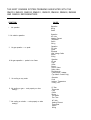
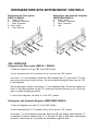
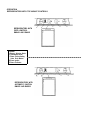
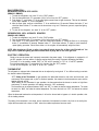
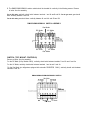
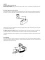
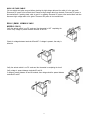
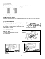
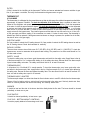
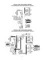
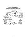
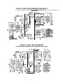
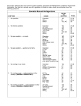
SERVICE TIPS
Efl Dometic@
MANUAL
REFRIGERATORS
Models
RM2310
RM2410
RM2452
RM2453
RM2552
RM2553
Copyright 1996 The Dometic Corporation
RM2510
RM2610
RM2810
OS1717 4/96
THE MOST COMMON SYSTEM PROBLEMS ASSOCIATED WITH THE
RM2310, RM2410, RM2510, RM2610 , RM2810, RM2452, RM2453, RM2552
AND RM2553 REFRIGERATORS
SYMPTOM
No operation.
1.
CAUSE
Operation
Wiring
Switch
2. No electric operation.
Operation
AC Volts
Heating Element
Thermostat
Switch
Wiring
3. No gas operation - no spark.
Operation
DC Volts
Igniter
Electrode
High Voltage Cable
Switch
Wiring
4. No gas operation - sparks but no flame.
Operation
LP gas
Filter
Orifice
Burner
Shut-off Valve
Safety Valve
Thermocouple
Thermocouple Adapter,
(Top Mount Controls Only)
5.
Operation
Level
Ambient Temperature
Cooling Unit
No cooling on any mode.
6. No cooling on gas - cools properly on other
mode(s).
LP Gas
Thermostat
Filter
Orifice
Burner
Flue Baffle
Flue Tube
7. No cooling on electric - cools properly on other
mode(s).
AC Volts
Heating Element
Thermostat
Switch
Wiring
SYMPTOM
CAUSE
8.
Insufficient cooling on all modes.
Operation
Level
Ventilation
Ambient Temperature
Air Leaks
Thermostat
Cooling Unit
9.
Insufficient cooling on electric - cools
properly on other mode(s).
AC Volts
Heating Elements
Thermostat
10.
Insufficient cooling on gas.
Cools properly on other mode(s).
LP Gas Pressure
Thermostat
Filter
Orifice
Burner
Flue Baffle
Flue Tube
11.
Freezes on electric - cools properly on
other mode(s).
Thermostat
Wiring
12.
Freezes on gas - cools properly on other
mode(s).
Bypass Screw
Thermostat
13.
Won’t stay lit on gas.
LP Gas
Safety Valve
Thermocouple
Thermocouple Adapter,
(Top Mount Controls Only)
Flame Failure Meter
(Top Mount Controls Only)
Flue Baffle
Flue Cap (Bottom Mount
Controls Only)
Orifice
Burner
14.
Rapid formation of frost.
Food Storage
Air Leaks
Interior Liner Seal to Frame
High Humidity
15.
No DC operation - cools properly on AC
and gas.
DC Volts
Heating Element
Switch
Wiring
Relay (RM261O/RM2810)
16.
Insufficient cooling on DC- cools properly
on AC and gas.
DC Volts
Heating Element
Relay (RM2610/RM2810)
17.
RM2510/RM2610/RM2810
On gas mode, sparks while flame is lit.
Electrode
LP Gas
Bypass Screw
Filter
REFRIGERATORS WITH BOTTOM MOUNT CONTROLS
Refrigerators with Piezo lgnitors
(RM2310 & RM2410)
Refrigerators with Automatic Reigniters
(RM251O/RM261O/RM2610)
A - ON/OFF Switch
B - Thermostat Gas/Electric
c - Safety Push-button
D - Piezo lgnitor
E - Flame View Port
A
B
c
E
-
-
-
ON/OFF Switch
Thermostat, Gas/Electric
Safety Push-button
Light
GAS OPERATION
Refrigerators with Piezo lgnitor (RM2310 & RM2410)
To start the refrigerator, turn knob “A” to the “GAS” position.
Turn the thermostat knob “B” one-quarter (l/4) of a turn from the “OFF” position.
Push button “C” in until it bottoms out-and hold. While holding button “C”, push button “D” for the
piezo ignitor several times to light the burner. This can be observed through the flame view port, “E”,
on the refrigerator.
After the flame lights, continue to hold button “C” for an additional fifteen (15) seconds. Release the
button “C” and check the flame view port “E” to make sure the burner does not go out. If the burner
goes out, repeat the lighting procedure.
To shut off the refrigerator, turn Knob “A” to the “OFF” position.
Refrigerators with Automatic Reigniters (RM2510/RM2610 /RM2810)
To start the refrigerator, turn knob “A” to the “GAS” position.
Turn the thermostat knob “6” one-quarter (l/4) of a turn from the “OFF” position.
Push button “C” in until it bottoms out-and hold. When lamp “E” stops flashing, hold push-button “C”
an additional 15 seconds. Release button “C”. If the lamp “E” starts to flash again, repeat lighting
procedure. If flame blows out, the reigniter will automatically relight the flame.
4
NOTE: After changing an LP tank, or after a long shut off period, the gas line is likely to be filled
with air. You may have to repeat the lighting procedure several times to purge the air out of the
gas lines.
ELECTRIC OPERATION
Check to be sure the power cord is properly connected to the power supply. If the refrigerator is
equipped for 12 volt DC operation, the tow vehicle engine should be running to prevent discharging
the battery.
Turn knob “A” to the position marked “ELEC” for 120 volt AC operation or “12V” for 12 volt DC
operation.
Turn the thermostat knob “B” one-quarter (l/4) of a turn from the “OFF” position.
To shut off the refrigerator, turn knob “A” to the “OFF” position.
THERMOSTAT
The refrigerator is equipped with a thermostat that can be adjusted by turning knob “B” to a different
setting to maintain the desired cabinet temperature.
“OFF” Setting of the Thermostat: In gas operation, the thermostat closes its main valve and the
burner runs continuously at the bypass rate or pilot. In electrical operation, the contacts in the thermostat are open and the heating elements are off.
“MAX” Setting of the Thermostat: In gas operation, the thermostat allows the burner to remain on
high flame continuously. In electric operation, the heating element is “ON” continuously.
The thermostat can be adjusted between “MAX” and “OFF” to obtain the desired cabinet temperature. The closer the knob is to “MAX”, the colder the cabinet temperature. The closer the knob is to
“OFF”, the warmer the cabinet temperature.
When the thermostat reaches the set temperature, it will cut the burner back to bypass or, in electric
operation, shut off the heating element.
OPERATION
REFRIGERATORS WITH TOP MOUNT CONTROLS
REFRIGERATORS WITH
PIEZO IGNITORS:
RM2452 AND RM2453
LEGEND:
A Energy Selector Knob
B Thermostat Knob
C Flame Failure Safety
Valve Push Button
D Piezo lgnitor
E Flame Indicator
---_-__-----m-------------v-
REFRIGERATORS WITH
AUTOMATIC IGNITION:
RM2552 AND RM2553
GAS OPERATION
REFRIGERATORS WITH PIEZO IGNITOR
(RM2452 & RM2453)
1. To start the refrigerator, turn knob “A” to the “GAS” position.
2. Turn the thermostat knob “B” one-quarter (1/4) of a turn from the “OFF” position.
3. Push button “C”, push button “D” for the piezo ignitor several times to light the burner. This can be observed
on the flame indicator “E”, on the refrigerator.
4. After the flame lights, continue to hold button “C” for an additional ten (10) seconds. Release the button “C” and
check the flame indicator “E” to make sure the burner does not go out. If the burner goes out, repeat the lighting
procedure.
5. To shut off the refrigerator, turn knob “A” to the “OFF” position.
REFRIGERATORS WITH AUTOMATIC REIGNITERS
(RM2552 AND RM2553)
1. To start the refrigerator, turn knob “A” to the “GAS” position.
2. Turn the thermostat knob “B” one-quarter (l/4) of a turn from the “OFF” position.
3. Push button “C” in until it bottoms out - and hold. When flame indicator “E” shows the flame is on, hold push
button “C” an additional 15 seconds. Release button “C”. If the flame indicator “E” starts to move toward off,
repeat lighting procedure. Should flame blow out, the reigniter will automatically relight the flame.
NOTE: After changing an LP tank, or after a long shut-off period, the gas line is likely to be filled with air. You
may have to repeat the lighting procedure several times to purge the air out of the gas lines.
ELECTRIC OPERATION
Check to be sure the power cord is properly connected to the power supply. If the refrigerator is equipped for 12
volt DC operation, the tow vehicle or caravan engine should be running to prevent discharging the battery.
Turn knob “A” to the position marked “ELEC” for 120 volt AC operation or “12V” for 12 volt DC operation.
Turn the thermostat knob “9” one-quarter (l/4) of a turn from the “OFF” position.
To shut off the refrigerator, turn knob “A” to the “OFF” position.
THERMOSTAT
The refrigerator is equipped with a thermostat that can be adjusted by turning knob “9” to a different setting to maintain
the desired cabinet temperature.
“OFF” Setting of the Thermostat: In gas operation, the thermostat closes its main valve and the burner runs
continuously at the bypass rate or pilot. In electrical operation, the contacts in the thermostat are open and the
heating elements are off.
“MAX” Setting of the Thermostat: In gas operation, the thermostat allows the burner to remain on high flame
continuously. In electric operation, the heating element is “ON” continuously.
The thermostat can be adjusted between “MAX” and “OFF” to obtain the desired cabinet temperature. The closer
the knob is to “MAX”, the colder the cabinet temperature. The closer the knob is to “OFF”, the warmer the cabinet
temperature.
When the thermostat reaches the set temperature, it will cut the burner back to bypass or, in electric operation, shut
off the heating element.
The setting of the thermostat is not critical, but we recommend it be adjusted to maintain a dry frost on the cooling fins.
Adjust the thermostat knob closer to “MAX” when the outside temperature becomes warm.
AC VOLTAGE REQUIREMENTS
The proper operating range is 100 to 132 volts. Check the AC volts at the receptacle where the refrigerator is attached.
If voltage drops below 100 volts, cooling efficiency will decrease with voltage decrease.
AC COMPONENTS
HEATING ELEMENT
To check a heating element, remove the heater leads from the terminal block
and measure for proper resistance across the two leads.
You should obtain the following readings, plus or minus 10%:
RM2310 92
RM2410 92
RM2510 7 5
RM2610 48
RM2810 44
RM2452 69
RM2453 69
RM2552 69
RM2553 69
DC VOLTAGE REQUIREMENTS
The operational range is 10.5 to 15 volts DC. Check for proper voltage at the terminal block or blocks at the back of
the refrigerator. The power supply to the refrigerator must be fused.
DC COMPONENTS
SWITCH (BOTTOM MOUNT CONTROLS)
A. Remove all wires from the assembly.
For the DC mode, continuity should exist between terminals 1 and 1A and 2 and2A. (3-Way Models Only)
For the AC mode, you should have continuity between 4L and 4A and 5N and 5A.
RM2310 & RM2410 SWITCH ASSEMBLY
DC Mode
DC Mode
AC Mode
AC -Mode
B. The RM251O/RM261O/RM2810 selector switch should be checked for continuity in the following manner. Remove
all wires from the assembly.
For the DC mode, continuity should exist between terminals 1 and IA and2 and 2A. For the gas mode, you should
have continuity between 3 and 3A.
For the AC mode, you should have continuity between 4L and 4A and 5N and 5A.
RM251O/RM261O/RM2810 SWITCH ASSEMBLY
Gas Mode
DC Mode \ AC Mode
DC Mode
AC Mode
Gas Mode
SWITCH (TOP MOUNT CONTROLS)
Remove all wires from the assembly.
For the DC Mode (3-Way Models ONLY), continuity should exist between terminals 5 and 5a and 6 and 6a.
For the AC Mode, continuity should exist between terminals 1 and la and 2 and 2a.
For the Gas Mode (on refrigerators equipped with automatic REIGNITERS ONLY), continuity should exist between
terminals 4 and 4a.
RM2452/RM2453/RM2552/RM2553 SWITCH
Gas Mode
AC
Mode 1
‘DC Mode
Gas Mode
IGNITER
A. MODEL RM2310,2410,2452,2453
When the button is pushed, a spring loaded striker creates a spark. If there is no resistance when pressing the button,
the piezo igniter is defective.
B. MODEL RM2510,2610,2810,2552,2553
Check that the switch is in the gas mode and is completing the circuit. Next, verify proper voltage at the positive (+)
and ground (-) terminals of the igniter. The reading should be within one volt of incoming voltage at the terminal block.
HIGH VOLTAGE
Disconnect DC power at the terminal block. Remove high voltage cable from igniter. Reconnect DC power, the igniter
should produce a sparking sound.
ON MODEL RM2510,2610 AND 2810: With the igniter producing spark, set the meter on 20 volts DC or lower scale,
connect meter leads to L and ground terminals on the igniter. The meter should read a pulsating voltage.
The pulsating voltage allows a lamp to illuminate on the front of the refrigerator to advise the customer spark has been
produced.
ELECTRODE
Do a visual inspection for cracks or breaks on the ceramic insulator. Also, verify the mounting bracket is attached
properly to the electrode. Check the spark gap. It must be set at three sixteenths (3/16) of an inch and the tip of
electrode above the slots in the burner.
ELECTRODE
TlP
10
HIGH VOLTAGE CABLE
Be sure switch and igniter are good before checking the high voltage cable and the switch is in the gas mode.
Disconnect DC power at the terminal block. Disconnect high voltage cable from electrode. Reconnect DC power to
the terminal block. If sparking starts, cable is good. If no sparking, disconnect DC power at the terminal block and then
disconnect high voltage cable at the igniter. Reconnect DC power to the terminal block.
RELAY (RM261 0/RM2810 3-WAY
MODELS ONLY)
Verify the selector switch is on DC mode and the thermostat is NOT completing the
circuit. Verify voltage is present between terminals 85 and 30.
+
Check for voltage between terminals 85 and 87. If voltage is present, the relay is
defective.
Verify the selector switch is on DC mode and the thermostat is completing the circuit.
Verify voltage is present between terminals 85 and 86.
If voltage is present, between 85 and 86 terminals, then voltage should be present between
terminals 85 and 87.
A
11
HEATING ELEMENT
(3-WAY MODELS ONLY)
Check the heating element with ohms resistance using a properly calibrated ohm meter.
You should obtain the following readings, plus or minus 10%:
1.15 OHMS
RM2310
1.15 OHMS
RM2410
.82 OHMS
RM2510
.67 OHMS
RM2610
RM2810
.67 OHMS
RM2453
.83 OHMS
RM2553
.83 OHMS
A continuity reading will indicate an open or complete circuit.
FLAME INDICATOR METER
If the millivolts from the thermocouple are 5 millivolts or more, the red needle in the meter should be in the green section.
LP GAS REQUIREMENTS
The LP gas pressure to the refrigerator should be 11 inches water
column with half of all BTU’s of the RV turned on. With all other
appliances turned off, the pressure to the refrigerator should not
exceed 12 inches water column. To check the gas pressure when
the refrigerator is operating, there is a pressure test housing
located just prior to the orifice.
- -*‘PRESSURE TEST HOUSING
LP GAS COMPONENTS
REFRIGERATORS WITH
BOTTOM MOUNT
CONTROLS
SHUT-OFF VALVE
To check the shut-off valve, remove and inspect
for any obstructions.
MANUAL GAS SHUTOFF VALVE
REFRIGERATORS WITH TOP MOUNT CONTROLS
/
MANUAL
GAS VALVE
MANUAL
GAS VALVE
12
FILTER
A filter is located in the inlet fitting to the thermostat. The filter can become saturated and cause a restriction to gas
flow. If you suspect a restriction, first verify the thermostat and bypass screw are good.
THERMOSTAT
LP GAS MODE
The thermostat is calibrated by the manufacturer so that at mid-range the cabinet temperature should be
approximately 40 degrees Fahrenheit. To check the calibration of the thermostat, place a container of water in the
cabinet of the refrigerator and operate at mid-range setting until the thermostat is satisfied. Check the temperature
of the water. It should be approximately40 degrees. To check the thermostat for proper g a s flow, set the thermostat
to maximum and check the gas pressure at the pressure test port. It should be line pressure, between 11 to 12 inches
water column. If you have less than 11 inches of water column pressure, the next step would be to shut off the gas
supply and remove the bypass screw. Then install a bypass screw that does not have the small o-ring on it. Next, turn
on the gas supply and take a reading. If the manometer now reads 11 inches of water column, the thermostat is
defective and must be replaced. If the bypass screw test shows no change in pressure, the problem lies in the filter,
the shut-off valve or the gas supply.
ELECTRIC MODE
On 2-way models it controls the AC heating element. On 3-way models it controls the DC heating element as well as
the AC heating element. Check the thermostat for continuity.
BYPASS SCREW
There are three common sizes of this screw: S-17 (350 BTU), S-14 (325 BTU) and S-l 1 (300 BTU). To check the
bypass screw, connect a manometer at the pressure test housing. The pressure on low flame mode should be 2 to
4 inches water column.
SAFETY VALVE
To check the safety valve, use a known good thermocouple and install into the safety valve. Supply flame to the tip
of the thermocouple for 2 to 3 minutes while holding in on the safety valve stem. Remove flame from thermocouple
tip and release safety valve stem. The safety valve should hold in for at least 30 seconds.
THERMOCOUPLE
It will produce 14 to 30 millivolts DC in normal operation. To check the thermocouple, use a known good safety valve
and attach to the thermocouple. Next, supply flame to the tip of the thermocouple for 2 to 3 minutes while depressing
the safety valve. Remove the flame and release the safety valve. The valve should hold for at least 30 seconds. If it
does not hold the safety valve open for 30 seconds.
THERMOCOUPLE ADAPTER
The thermocouple adapter is a device that allows the flame indicator meter to read DC millivolts from the thermocouple.
Remove it from its location and do a continuity test from the terminal to the center post. Continuity should exist. Next,
check for continuity between the terminal and casing. No continuity should exist.
BURNER
It should be level and the slots in the burner should be directly below the flue tube. The burner should be cleaned
periodically, at least once a year.
FLUE BAFFLE
It should be cleaned periodically, at least once a year.
FLUE CAP - BOTTOM MOUNT CONTROLS
It must be properly attached or flame outage could occur.
13
hElllV8
n
”
hm11v8
n
I---___’
ESSZW~/Ol8ZW~/Ol9ZWtl/OlSZWtl
IO GU!YJOM SJB noA lapow all1 Jo! WeJfhp BU!J!M ayi Jad paJ!~ s! Jote~aQJla~ aqt ,QJ~A
sJow7puo3 0~ au140 Jaql!a ~04 alrylsqns
se ap!qaA au1 40 s!ssey3 Jo Apoq aut asn lou oa
DNltllM lVNU31NI
‘kEllV3H l-IO/\ 3Cl P=lJ’=’
y3Olq leU!UJJal aY101 apeW S! UO!~3aUUO3 S!ql :(@lO
*a
3a SIlOA Zl PayJEW y3Olq Il?U!WJal ayl 01 E$E?lU
S! uoy3auuo3 aq1 :p
‘3
WPWI AeM-E) Jd
-6nld s!ql WOJ~ 6uoJd 6u!
-pUnOJ6 aql aAOUJaJ JOln3lON oa *al3sldaceJ 6uoJd
aalyl papunoJ6 AlJadoJd e og I(l~)a~!p pa66nld
a q PlnOyS pue SpJEZZEq y3oys ~J!F?BB UO!palOJd
~04 6nld (papunoJ6) 6UOJd-aaJqi t? L&M paddgba
S! JOleJa6!JjaJ aql :UO!~tX3UuO~ 3v Sllon ()zc ‘V
DNltllM lVNt131X3
SlEl13W1133d NI
HItIN 3UlM ~013flClN03 -IV101 Wi’lWlXVW
:9NlkllM
EP#
EP#
EP#
EP#
ESSZWtl
zsszwkl
ESPZWH
ZSPZIW
8S#
0 18ZWkl
E9#
0 19ZNtl
EP#
OlciZWki
6E#
OCPZWtl
66#
OCGZWtl
:SMOllOl SE!
S! JOlE?Jatj!J4aJ l~nlEUJ EN.# JOi aD!l!JO SZ!S I3SJJO3 C3L(l *Jeah I2 XXI0 ISt?t3l$?? ‘I(llw!po!Jad palEal aq PlnOqS Xl!4!JO ayl
33Ult10
*leaA e aDuo y~t?al 112 ‘&xNpo!Jad paueal3 aq w-cu $1
38fll3fll~
TYPICAL 2-WAY WITH PIEZO IGNITER
FOR REFRIGERATORS WITH BOTTOM MOUNT CONTROLS
1
123 VOLTS AC
TYPICAL 3-WAY WITH PIEZO IGNITER
FOR REFRIGERATORS WITH BOTTOM MOUNT CONTROLS
12 VOLTS DC
r--Y
12 VOLTS DC
+z
I20 V O L T S A C
-------$
120 VOLTS AC
H
THERMOSTAT
JUNCTION BLOCK
15
TYPICAL 2-WAY WITH REIGNITER
FOR REFRIGERATORS WITH BOTTOM MOUNT CONTROLS
I
12 VOLTS DC !
16
120 VOLTS AC
r
12 VOLTS DC
TYPICAL 3-WAY WITH REIGNITER AND RELAY
F O R
R E F R I G E RBOlTOM
A T O R MS O U
W N
I TT H C O N T R O L S
12 Volts DC
‘7
120 Volts AC
I-?
TYPICAL 3-WAY WITH REIGNITER
FOR REFRIGERATORS WITH BOTTOM MOUNT CONTROLS
12 VOLTS DC
+I2 VOLT: DC
12 VOLTS DC
+
,*---,
P
( ,___
cd/ y,
II-:
120 VOLTS A C
L
PP
:
e
+
4
12 VOLTS DC
c-q
-o___P +
@
!1
-fiBLACK
0” GREEN
GREEN/YELLOW
@
17
120 VOLTS AC
l-9
TYPICAL 2-WAY WITH PIEZ0 IGNITOR
FOR REFRIGERATORS WITH TOP MOUNT CONTROLS
GROUND
&
120 VOLTS AC
ADAPTER
120 VOLTS AC
O[
D
@
AC
@-SWITCH
C-TERMINAL BLOCK
@-THERMOSTAT
@----HEATER 120~
@---BLACK
Q-BROWN
3 - -R E D
4-YELLOW/GREEN
@-+xEEN
@-BL.UE
@--MY
8 WHITE
o-
61
lVlSOWtUHl--@
MO18 lVNIRM31~
tKuIMS-@
t131lN313tl~
3 AOZI WV3H--@
+
I
30 AZ1
-+
1
3v SI:OA
azl
x! SllOA
SlOtllN03 1NnOW d01 HUM StlOlVtl3Dlkl~3tJ tlOA
tlOllNWk4 HUM AWM-2 lW3ldA.l
TYPICAL 3-WAY WITH PIEZO IGNITOR
FOR REFRIGERATORS WITH TOP MOUNT CONTROLS
12 VOLTS DC
120 V O L T S A C
@-HEATER 12v DC
@HEATER 120V AC
C-SWITCH
@-TERMINAL BLOCK
(&THERMOSTAT
GROUND
&
Q
4
+
+
+-
12V DC
20
TYPICAL 3-WAY WITH REIGNITOR
FOR REFRIGERATORS WITH TOP MOUNT CONTROLS
12
V O L T S DC
12
120 VOLTS AC
;ROUNO
*HEATER 12V oc
21
VOLTS
DC
OTHER
LEVELING
Refrigerators have a type of cooling unit that utilizes an enclosed pump tube surrounded by a solution to protect the
assembly. To ensure proper leveling with these models, the vehicle needs to be leveled so it is comfortable to live in.
(No noticeable sloping of floor or walls). When the vehicle is moving, leveling is not critical as the rolling and pitching
movement of the vehicle will pass to either side of level, keeping the refrigerant from accumulating in the piping.
VENTILATION
In a proper installation there should be zero (0”) clearance surrounding the sides and top of the refrigerator to achieve
proper air flow.
In addition, the cooling unit should have the following clearances to the nearest surface made of combustible material:
RM2310
1
INCH
RM2410
1/2
INCH
RM2510
1/2
INCH
RM2610
1/2
INCH
RM2810
1/2
INCH
RM2452
0
INCH
RM2453
0
INCH
RM2552
0
INCH
RM2553
0
INCH
RM2510/ RM2610/RM2810 /
RM2452/RM2453/RM2552RM2553
RM231 O/RM2410
n
TURNING VANE
ROM SIDE OF
PATH OF AIR FLOW
CLEARANCE
FROM SIDE OF
CLEARANCE FR
COMBUSTIBLE
MATERIALS
AIR LEAKS
Check the gasket on the doors to be sure of a positive air seal. Check that the cooling unit is installed properly.
22
DOOR POSITION
To correct an alignment of the door, loosen the hinge screws slightly, and reorient the door in the proper position.
If the door needs more adjustment than is available through the hinge adjustment, the base can be repositioned to
reorient the door.
AMBIENT TEMPERATURE
As the ambient temperature increases, the air temperature in the area of the cooling unit increases.
COOLING UNIT
To check the cooling unit, first verify the AC heating element is good. Then place approximately one gallon of water
inside the refrigerator and place a thermometer in one of the containers of water. Supply 115 volts direct to the AC
heating element and operate for at least 12 hours. Check the temperature on the thermometer. It should be at 45
degrees or lower depending on test conditions.
FOOD STORAGE
Rearrange your foodstuffs. It is essential that the shelves are not covered with paper or large storage containers.
Always remember to allow for proper air circulation. Odorous or highly flavored foods should always be stored in
covered dishes, plastic bags or wrapped in foil or waxed paper to prevent food odors. Vegetables, lettuce, etc., should
be covered. NEVER PUT HOT FOOD INTO THE REFRIGERATOR.
HIGH HUMIDITY
High humidity may cause a small amount of condensation to form on the frame of the refrigerator. As the humidity is
reduced, the sweating will decrease.
INTERIOR LINER SEAL TO FRAME
There is a seal that is applied to the liner in the area where the metal frame makes contact with the interior liner. Cold
air can migrate out to the metal frame.
Clean the metal frame and foil-backed insulation around the refrigerator. Apply a foil-backed adhesive tape to the joint
between outer frame and foil-backed refrigerator insulation. Make sure the refrigerator is dry and that the surface
temperatures are above 50°F. Use a clear silicon caulking compound and seal the seam between the refrigerator’s
plastic liner and the metal frame. NOTE: TO FORM A PROPER SEAL, IT IS IMPORTANT NOT TO LEAVE ANY
GAPS.
DOUBLE DOOR
REFRIGERATOR
SHOWN WITH
DOORS REMOVED
23