1
D9412GV3/D7412GV3 v8.11 and Higher
Program Entry Guide
EN
Control Panels
D9412GV3/D7412GV3 | Program Entry Guide |
EN | 2
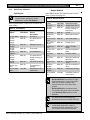
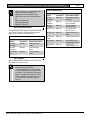
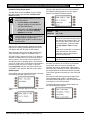
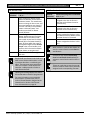
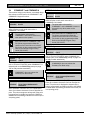
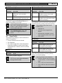
Documentation Conventions
Type Styles Used in this Manual
To help identify important items in the text, the
following type styles are used:
Prompt
A thick border is used to indicate
a main programming entry as
seen in the Remote
Programmer’s Display. It is used
as a section heading and screen
example. Shaded boxes indicate
programmer prompts that are
only available when Custom or
View events are selected.
Sub-Prompt
A dashed border indicates a sub
entry under a main programming
entry.
System Requirements
Minimum system requirements for
Classification in accordance with
ANSI/SIA CP-01-2007:
UL Listed and Classified control unit Model
D9412GV3 or D7412GV3
UL Listed and Classified keypad Model
D1256, D1257, D1260, D1255,
D1255R, or D1255 RW
UL Listed Local Bell
The minimum firmware requirements for SIA CP-01
compliance are:
Control Panel
Firmware Version
D9412GV3
8.11 or later
D7412GV3
8.11 or later
Trademarks
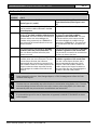
Warnings, Cautions, and Notes
Throughout this document helpful tips and notes are
presented concerning the entire application or
programming the unit. They are displayed as follows:
Warning!
These warn of the possibility of physical
damage to the operator, program and/or
equipment.
Caution
CoBox is a registered trademark of Lantronix.
These warn of the possibility of physical
damage to the program and/or equipment.
Windows is a registered trademark of Microsoft
Corporation in the United States or in other countries.
Important Notes
Molex is a registered trademark of Molex
Incorporated.
These notes should be heeded for
successful operation and programming.
Bosch Security Systems, Inc. | 10/11 | F01U170807-02
D9412GV3/D7412GV3 | Program Entry Guide |
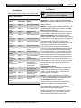
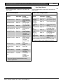
Table of Contents
1.0
1.1
1.2
1.2.1
1.3
Introduction................................................. 5
Using this Program Entry Guide................... 5
Guide to Programming Options.................... 6
Local Keypad Programming......................... 7
Guide to UL 864 Programming Requirements
9
2.0
Panel and Area Wide Parameters ........... 12
2.1
Phone ........................................................ 12
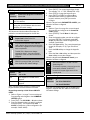
When the keypad reads Parameter Saved, your
selection has been configured.2.2 .Phone Parameters
2.2
Phone Parameters ..................................... 14
2.2.1 Special Point/User Reporting ..................... 15
2.3
Routing ...................................................... 17
2.3.1 Called Party Disconnect............................. 17
2.3.2 Route Number Groups: Which Has the
Highest Priority?......................................... 17
2.3.3 Programming Primary and Backup
Destinations ............................................... 18
2.3.4 Enhanced Routing ..................................... 18
2.3.5 Programming a Duplicate Report ............... 18
2.3.6 Routing Destination Communication Failures
................................................................... 18
2.3.7 Message Prioritization within a Route Number
................................................................... 18
2.3.8 Communication Attempts ........................... 18
2.3.9 Route Group Categories ............................ 21
2.3.10 Event Priority.............................................. 27
2.4
Power Supervision ..................................... 29
2.5
Printer Parameters..................................... 30
2.6
RPS Parameters ........................................ 32
2.6.1 Uploading and Downloading Reports......... 32
2.6.2 Log Threshold Reports............................... 32
2.6.3 Panel Initiated Unattended RPS................. 32
Select the baud rate for RPS-to-control panel
communication when using a PSTN connection.2.7
Miscellaneous ............................................ 35
2.7
Miscellaneous ............................................ 36
2.8
Area Parameters........................................ 36
2.8.1 Area Parameters........................................ 36
2.8.2 Shared-Area Characteristics ...................... 41
2.8.3 Bell Parameters ......................................... 41
2.8.4 Open/Close Options................................... 43
2.8.5 Arming Features ........................................ 47
2.9
Keypad (Command Center) ....................... 50
2.9.1 Keypad (Command Center) Assignment.... 50
2.9.2 Area Text ................................................... 56
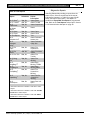
2.10
User Interface ............................................ 59
2.10.1 Commands ................................................ 60
Bosch Security Systems, Inc. | 10/11 | F01U170807-02
EN | 3
2.10.2 Command Authorization............................. 60
2.10.3 Access Control Functions........................... 62
2.10.5 Configuration Authority................................. 66
Keypad Programming of the Keypad Programming
Option 67
2.10.6 Authority Level Selections .......................... 67
2.10.7 Access Control Levels................................ 75
2.10.8 SIA Duress Passcode Options ................... 77
2.11
Function List............................................... 77
2.12
Relay Parameters ...................................... 78
2.12.1 Area Relays ............................................... 79
2.12.2 Panel-Wide Relays.....................................
81
13
2.1
Passcode or Token Worksheet .................. 82
2.1.1 User Groups............................................... 83
2.1.2 Passcodes ................................................. 83
2.1.3 User Group Window................................... 83
2.1.4 User Name................................................. 83
2.1.5 Tokens and Cards...................................... 83
2.1.6 Reporting and Logging ............................... 84
3.0
Points ......................................................... 87
3.1
Point Index ................................................. 87
3.2
Point Responses ........................................ 91
3.2.1 Applications for Point Responses 9, D, and E:
................................................................... 91
3.2.2 Characteristics of a Fire Point: ................... 91
3.3
Point Assignments ................................... 101
3.4
COMMAND 7 and COMMAND 9.............. 104
4.0
Schedules (Skeds) .................................. 105
4.1
Windows .................................................. 105
4.1.1 Opening and Closing................................ 105
4.1.2 User Group Windows ............................... 112
4.1.3 Holiday Indexes for User Group Windows 114
4.2
Schedules (Skeds) ................................... 114
4.3
Holiday Indexes........................................ 124
4.3.1 Add/Change/Delete.................................. 124
5.0
AUXPARM................................................ 125
5.1
Introduction .............................................. 125
5.2
RPS Requirements .................................. 125
5.3
SDI Automation ........................................ 125
5.4
SDI RPS Parameters ............................... 126
5.4.1 Configuration for RPS Over Network........ 127
5.5
Programming Path Numbers and IP
Addresses for Enhanced Communications ........... 131
5.5.1 Ant-Replay Security Feature .................... 135
5.6
SDI RPS/Enhanced Communications
Configuration ........................................................ 135
5.7
Route Group Parameters ......................... 136
5.8
Miscellaneous .......................................... 137
5.9
Cross Point Parameters ........................... 139
6.0
ACCESS CONTROL ................................ 140
D9412GV3/D7412GV3 | Program Entry Guide |
6.1
Door Profile .............................................. 140
6.2
Strike Profile............................................. 143
6.3
Event Profile............................................. 145
7.0
SIA CP-01 Quick Reference ................... 147
Programming Prompts Directory....................... 148
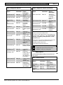
Figures
Figure 1:
EN | 4
Table 25:
Table 26:
Table 27:
Table 28:
Table 29:
Table 30:
D1255 Keypad Programming Menu and
Page References................................... 7
Figure 2: D1260 Keypad Programming Menu and
Page References................................... 8
Figure 3: Softkey Locations on the D1260 Keypad
............................................................ 58
Figure 4: User Group 122 Example ........................ 84
Figure 5: Example Opening Window Timeline (using
two Opening Windows on same day) 107
Figure 6: COMMAND 43 Flow Chart (D1255)....... 128
Figure 7: COMMAND 43 Flow Chart (D1265)....... 129
Figure 8: Poll Rate Timeline.................................. 134
Table 31:
Tables
Table 40:
Table 1:
Differences between the D9412GV3 and
D7412GV3............................................. 5
Table 2:
Literature Referenced ............................ 5
Table 3:
UL 864 Programming Requirements ..... 9
Table 4:
UL 864 Programming Recommendations
............................................................ 11
Table 5:
Modem IIIa2 Communication Format Data
- User ID Numbers............................... 15
Table 6:
Modem IIIa2 Communication Format Data
– Point Numbers.................................. 15
Table 7:
D6000 User IDs and Zones ................. 15
Table 8:
SDI Path Number by Device ................ 18
Table 9:
Fire Reports......................................... 21
Table 10: Burglar Reports ................................... 21
Table 11: User Reports ....................................... 22
Table 12: Test Reports ........................................ 23
Table 13: Diagnostic Reports .............................. 24
Table 14: Relay Reports...................................... 24
Table 15: Auto-Function Reports......................... 25
Table 16: RPS Reports........................................ 25
Table 17: Point Reports....................................... 26
Table 18: User Change Reports .......................... 26
Table 19: Access Reports ................................... 27
Table 20:Event Descriptions, Priorities, and Numbers
............................................................ 27
Table 21: Verify Time .......................................... 39
Table 22: CF### Key Strokes ............................. 58
Table 23: CF### Custom Function Keystrokes ... 58
Table 24: Keypad Programming Choices ............ 60
Bosch Security Systems, Inc. | 10/11 | F01U170807-02
Table 32:
Table 33:
Table 34:
Table 35:
Table 36:
Table 37:
Table 38:
Table 39:
Authority Level Selections.................... 67
L## Secure Door-Door Mode Definitions
............................................................ 71
Bypassing a Point ................................ 98
P### Relay Codes/Relays ................. 103
Window Selections ............................ 105
Programming for Two Same Day
Opening Windows (refer to Figure 5) . 108
Programming to Link Two Days over
Midnight*............................................ 108
Programming Example: Linking Two
Closing Windows over Midnight ......... 109
Opening and Closing Windows
Worksheet ......................................... 111
Opening and Closing Windows .......... 111
Normal Store Hours*.......................... 111
Delivery Schedule* ............................ 112
Monthly Auditor’s Schedule* .............. 112
Cross Point Ranges Within Groups ... 140
Effects of Programming on Custom
Function Activation ............................ 141
Programming the Control Panels for SIA
CP--01 Compliance ........................... 147
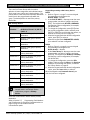
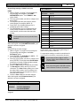
D9412GV3/D7412GV3 | Program Entry Guide | 1.0
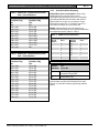
Using this Program Entry Guide
This guide is only for programming the D9412GV3
and D7412GV3 Control Panels.
Although this guide specifically refers to the
D9412GV3 Control Panels, it can be used for
programming the D7412GV3 Control Panels.
Differences between the D9412GV3 and D7412GV3
are shown in Table 1 on page 5.
Table 1: Differences between the D9412GV3
and D7412GV3
Features
Access Control
Expanded users
Passcodes
Cards/tokens
Passcode-protected
custom functions
Number of printers
Number of points
Number of relays
Areas
EN | 5
Table 2: Literature Referenced
1.0 Introduction
1.1
Introduction
D9412GV3
Eight Doors
D7412GV3
Two Doors
249
996
16
99
396
4
3
246
128
1
75
64
32
8
Bosch Security Systems, Inc. | 10/11 | F01U170807-02
Document Name
D1255 Installation Instructions
Part Number
D1256/D1257 Installation
Instructions
D1255RBD1256RBD1257RB
Installation Instructions
D1260 Installation Guide
74-06925-000
F01U011791
D1260 Owner’s Manual
50410
D6500 Report Directory
74-04651-001
Conettix D6600/6100
Receiver/Gateway Program Entry
Guide
Conettix D6600/6100
Receiver/Gateway Computer
Interface Manual
D720 Series Installation Guide
4998122702
D9210B Operation and
Installation Guide
D9210B Program Entry Guide
32206
D9210B Program Record Sheet
32208
D9412GV3/D7412GV3 Operation
and Installation Guide
D9412GV3/D7412GV3 Program
Record Sheet
RPS Installation Guide
F01U143070
74-06819-000
48101
4998122703
74-06918-000
32207
F01U170809
4998141259
D9412GV3/D7412GV3 | Program Entry Guide | 1.0
1.2
Introduction
EN | 6
Guide to Programming Options
Full configuration of the control panel is only achieved through use of the Remote Programming Software
(RPS). A limited keypad programmer’s mode is available to modify some of the more commonly changed
parameters.
This guide is set up in a specific order. Related program entries are grouped together in modules as they
appear in RPS.
This guide shows the programming options for each programming prompt. Each option is listed with:
The Program Item Prompt: Each prompt is shown as it appears in RPS. Refer to the RPS Installation
Guide (P/N: 4998141259).
Program Entry Default Setting: Because defaults are set for the typical installation, programming each
prompt might not be necessary. Review the default entries in the program record sheet shipped with the
control panel to determine which prompts must be programmed.
Program Entry Selections: Only the selections listed can be used for a particular program item.
Program Entry Description: Describes the various entry selections. Read the descriptions carefully to
avoid improperly programmed equipment.
Bosch Security Systems, Inc. | 10/11 | F01U170807-02
D9412GV3/D7412GV3 | Program Entry Guide | 1.0
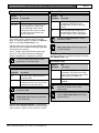
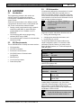
1.2.1
Introduction
EN | 7
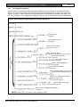
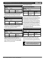
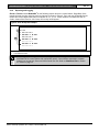
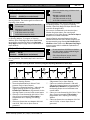
Local Keypad Programming
GV3 now offers a Local Keypad Programming menu with the Service Passcode only. It includes all custom
options. For a list of program items you can set using Keypad Programming, refer to Figure 1 on page 7 and
Figure 2 on page 8. To access the Keypad Programming menu, the Keypad Programming option must be set
to P (refer to Section 2.10.5 Configuration Authorityon page 66), and all control panel areas must be disarmed.
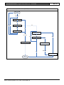
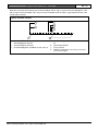
Figure 1: D1255 Keypad Programming Menu and Page References
Refer to Phone #
on page 12.
Refer to Phone # Format
on page 13.
Refer to Enhanced Comm
on pages 130 to 132.
Refer to R# Primary Device
on page 18 and R# Backup Device on page 19.
Refer to RPS Passcode
on page 32.
Refer to RPS Phone #
on page 34.
Refer to RPS IP Address #
on page 129.
Refer to RPS Port Number
on page 129.
Refer to Area# Area On on page 36 and
Area# Account Number on page 36.
Refer to CC# Enhanced Command
Center on page 51 and
CC# Scope on page 55.
Refer to P### Point Index
on page 101.
Refer to 2.10.5 Configuration Authority
on page 67.
Bosch Security Systems, Inc. | 10/11 | F01U170807-02
D9412GV3/D7412GV3 | Program Entry Guide | 1.0
Introduction
EN | 8
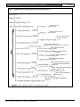
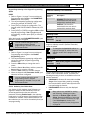
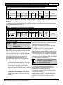
Figure 2: D1260 Keypad Programming Menu and Page References
Refer to Phone #
on page 12.
Refer to Phone # Format
on page 13.
Refer to Enhanced Comm
on pages 130 to 132.
Refer to R# Primary Device
on page 18 and R# Backup Device on page 19.
Refer to RPS Passcode
on page 32.
Refer to RPS Phone #
on page 34.
Refer to RPS IP Address #
on page 129.
Refer to RPS Port Number
on page 129.
Refer to Area# Area On on page 36
and Area# Account Number on
page 36.
Refer to CC# Enhanced Command
Center on page 51 and
CC# Scope on page 55.
Refer to P### Point Index
on page 101.
Refer to 2.10.5 Configuration Authority
on page 67.
Bosch Security Systems, Inc. | 10/11 | F01U170807-02
D9412GV3/D7412GV3 | Program Entry Guide | 1.0
1.3
Introduction
EN | 9
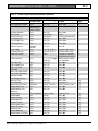
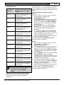
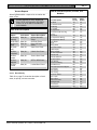
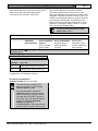
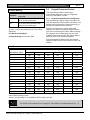
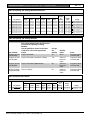
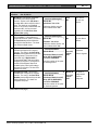
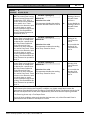
Guide to UL 864 Programming Requirements
This section identifies the programming requirements you must make in order to comply with UL 864
Commercial Fire applications.
NOTICE TO USERS, INSTALLERS, AUTHORITIES HAVING JURISDICTION, AND OTHER
INVOLVED PARTIES
This product incorporates field-programmable software. In order for the product to comply with the
requirements in the Standard for Control Units and Accessories for Fire Alarm Systems, UL 864,
you must limit certain programming features or options to specific values. Refer to Table 3.
Table 3: UL 864 Programming Requirements
Product Feature/Option
Possible Settings
Settings Permitted in
UL 864
Refer to
Page:
If using two phone lines:
Phone 1 through 4
Yes
24 characters
12
Phone Supervision
Alarm On Fail
Buzz On Fail
Two Phone Lines
Yes
No
Yes
Yes
0 to 240 sec
Yes / No
Yes / No
Yes / No
Expand Test Report
Fire Reports
R# Fire Supervisory
Missing
Test Reports
AC Fail Report
AC Restoral Report
Battery Missing Report
Low Battery Report
Battery Restoral Report
R# Service Start Report
R# Service End Report
R# Fire Walk St Report
R# Fire Walk End Report
R# Walk Test St Report
R# Walk Test End Report
AC Fail Time
AC Fail Display
AC Tag Along
AC/Battery Buzz
Yes
Yes
Required
Yes/No
Yes / No
Yes/No
Program a valid phone
number
10 to 200 sec
Set to No
Set to Yes
Set to Yes when using
PSTN communications.
Set to Yes
Set to Yes
Set to Yes
Yes
Yes
Yes
Yes
Yes
Yes
Required
Required
Required
Required
Required
Required
Yes
Yes
Yes
Yes
Yes / No
Yes / No
Yes / No
Yes / No
Yes / No
Yes / No
Yes / No
Yes / No
Yes / No
Yes / No
Yes / No
Yes / No
1:00 to 90:00 min
10 to 300 sec
Yes / No
Yes / No
Set to Yes
Set to Yes
Set to Yes
Set to Yes
Set to Yes
Set to Yes
Set to Yes
Set to Yes
Set to Yes
Set to Yes
Set to Yes
Set to Yes
Enter 1:00
10 to 200 sec
Set to Yes
Set to Yes
22
23 (Table 13)
23 (Table 13)
23 (Table 13)
23 (Table 13)
23 (Table 13)
26 (Table 17)
26 (Table 17)
26 (Table 17)
26 (Table 17)
26 (Table 17)
26 (Table 17)
29
29
29
30
Permitted in
UL 864? (Y/N)
Bosch Security Systems, Inc. | 10/11 | F01U170807-02
16
16
16
16
17
21
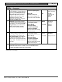
21 (Table 9)
D9412GV3/D7412GV3 | Program Entry Guide | 1.0
Introduction
EN | 10
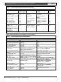
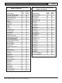
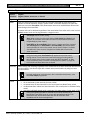
Table 3: UL 864 Programming Requirements (continued)
Product Feature/Option
Possible Settings
A# Fire Bell
A# Reset Sensors
U### Area # Auth
Permitted in
UL 864? (Y/N)
Yes
Required to
send system
status reports
Yes
Yes
Yes
Yes
Yes
Yes
Disable /
Enable
Yes
Yes
Yes
U### Passcode
Yes
P## Silent Bell
P## Invisible Point
P## Local While
Disarmed
P## Local While Armed
P## Disable Restorals
P## Bypassable
P## Swinger Bypass
P## Fire Point
P## Resettable
Sked## Function Code
Sked## Defer Test
Sked## Hourly Test
(Report?)
Sked## Time
Sked## Date
Sked## Sunday
Sked## Monday
Sked## Tuesday
Sked## Wednesday
Sked## Thursday
Sked## Friday
Sked## Saturday
Sked## Xept On Holiday
Bat Fail/Restoral Report
Area 1 Area On
A# Delay Restoral
Verify Time
Area # Fire Time
CC# Supervised
CC# Trouble Tone
CC# Scroll Lock
Remote Program
Yes / No
Yes / No
Settings Permitted in
UL 864
Set to Yes
Set to Yes
Refer to
Page:
30
36
Yes / No
10 to 60 sec
1 to 90 min
Yes / No
Yes / No
Yes / No
-, E, or P
Set to Yes
60 sec
5 min (check with AHJ)
Set to Yes
Set to Yes
Set to Yes
Set to P
38
38
42
51
54
56
65
0 to 128, A, B, C
0 to 128, A, B, C
0 to 8
79
79
85
No
No
No
3-, 4-, 5-, or 6-digit
passcode
Yes / No
Yes / No
Yes / No
Program with a relay
Program with a relay
Program an Authority
Level for the Fire Area
Must program at least
one passcode
Set to No
Set to No
Set to No
No
No
No
No
Yes
Yes
Required
No
No
Yes / No
Yes / No
Yes / No
Yes / No
Yes / No
Yes / No
1 to 11, 13 to 28
Yes / No
Yes / No
Set to No
Set to No
Set to No
Set to No
Set to Yes
As required
Sked Function Code 9
Set to No
Set to No
97
97
98
99
100
100
114
117
117
Enter valid time
No
Yes
Yes
Yes
Yes
Yes
Yes
Yes
No
00:00 to 23:59
mm/dd
Yes / No
Yes / No
Yes / No
Yes / No
Yes / No
Yes / No
Yes / No
Yes / No
00:00 to 23:59
Set to No
Set to Yes
Set to Yes
Set to Yes
Set to Yes
Set to Yes
Set to Yes
Set to Yes
Set to No
123
123
123
123
123
123
123
123
123
123
Bosch Security Systems, Inc. | 10/11 | F01U170807-02
85
93
94
96
D9412GV3/D7412GV3 | Program Entry Guide | 1.0
Introduction
EN | 11
Table 3: UL 864 Programming Requirements (continued)
Product Feature/Option
Possible Settings
Permitted in
UL 864? (Y/N)
For IP Communications to a D6600 Receiver
Enhanced Comm
Yes
Yes / No
Path1 IP Add1 (2, 3 or 4) Yes
000 to 255
Path 1 Poll Rate
Yes
Path 1 Ack Wait
Yes
Path 1 Retry Count
Yes
SDI 88 Supervision
Yes
For Ground Fault Enable Switch
Yes
(Refer to the
D9412GV3/D7412GV3
Operation and Installation
Guide (P/N:
F01U143070)
* Set the Path 1 Poll Rate to 65535 for 24 hr.
0, 5 to 65535 sec*
0, 5 to 65535 sec*
0 to 255
Yes / No
Closed = Enabled
Open = Disabled
Settings Permitted in
UL 864
Refer to
Page:
Set to Yes
Program a valid IP
address
Program as necessary
Program as necessary
Program as necessary
Set to Yes
131
131
132
135
135
136
Closed
N/A
The following programmable parameters are recommended by Bosch when installing a commercial fire alarm
system. Always check with your local Authority Having Jurisdiction.
Table 4: UL 864 Programming Recommendations
Prompt
Phone Line Fail Report
Phone Line Restoral Report
Fire Walk Start Report
Fire Walk End Report
Cancel Report
CC# Scope
CC# Enhanced Command
Center
CC# Menu Key Lock
Reset Sensors
Fire Test
L## Reset Sensors
Possible Settings
Yes / No
Yes / No
Yes / No
Yes / No
Yes / No
Panel Wide, Account Wide, Area
Wide, Custom, No Keypad
Yes / No
Recommendation
Yes
Yes
Yes
Yes
Yes
Do not program No Keypad
Yes / No
Disable/Enable/Passcode Protect
Disable / Enable / Passcode Protect
Disable / Enable
If using D1256RB, set to No
Enable
Enable
If Reset Sensor is set to Passcode
Protect, set this to Enable
If Fire Test is set to Passcode
Protect, set this to Enable
Program as 0
May be required for Waterflow,
otherwise No
Set to No for Fire devices.
No
L## Fire Test
Disable / Enable
U### User Group
P## Ring Until Restored
0 to 8
Yes / No
P## Cross Point
D# Fire Unlock
Yes / No
Yes / No
Bosch Security Systems, Inc. | 10/11 | F01U170807-02
Set to Yes, if applicable
D9412GV3/D7412GV3 | Program Entry Guide | 2.0
2.0 Panel and Area Wide
Parameters
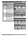
This section has twelve programming categories:
Panel and Area Wide Parameters
EN | 12
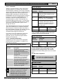
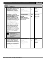
Phone #
Default:
Blank
Selection:
Up to 24 characters
Phone
0 to 9
Numbers 0 through 9
Phone Parameters
C
3-sec pause
Routing
D
7-sec dial-tone detection
Area Parameters
# or *
Power Supervision
Printer Parameters
RPS Parameters
Miscellaneous
Area Parameters
Used for the same purpose as
pressing this key on a telephone
keypad when manually dialing. For
example, an asterisk (*) may be
needed to access your long distance
service. Do not use these characters
when pulse dialing.
Keypad
Blank
Control panel dials no phone number.
User Interface
Function List
Relay Parameters.
2.1
Phone
The control panel can dial as many as four different
telephone numbers when sending event reports.
Refer to Section 2.3 Routing on page 17 for
information about event report routing and
communication protocols.
When using PSTN telephone lines,
program two telephone numbers to
meet UL 864 requirements.
Programming this item Blank does
not disable phone routing. To disable
reporting to this phone, refer to
Section 2.3 Routing on page 17.
This is the telephone number the control panel dials to
contact the central station receiver when sending
event reports. This number is Phone 1 referred to in
the prompts in Section 2.3 Routing on page 17.
The control panel waits for a break in the dial tone
after dialing the first digit. If the control panel must dial
a digit (for example, 9) to access an outside line, place
a C before the phone number. The control panel waits
2 sec and does not wait for the dial tone break.
The control panel is programmed with a 7-sec dial
tone detect period. When a dial tone is detected or the
waiting period ends, the control panel begins to dial.
To extend the dial tone detect period, place a D before
the phone number. To insert a pause during or after
dialing, use C in the number sequence. For example,
if the control panel hangs up before it hears the
Modem IIIa2 ACK tone from the D6500 or D6600,
program extra Cs after the phone number. The control
panel waits on line for two extra seconds for each C
programmed.
Enter up to 24 of the characters shown in the Phone #
table to define dialing characteristics.
For SIA CP-01 Compliance
Call Waiting Disable
If the telephone system at the installation site uses the
Call Waiting feature, ensure that the primary
telephone reporting number is programmed to disable
Call Waiting.
Bosch Security Systems, Inc. | 10/11 | F01U170807-02
D9412GV3/D7412GV3 | Program Entry Guide | 2.0
If you program the primary phone number with a
sequence to temporarily disable Call Waiting
(typically *70 pause, but verify with the phone service
provider) followed by the phone number, you should
program the backup phone number without the Call
Waiting cancel sequence. If the subscriber cancels
Call Waiting without notifying their alarm installing
company, the control panel can still send reports
using the backup number.
Dialing a Call Waiting sequence on a
non-Call Waiting line prevents the system
from dialing the central station receiver
successfully.
Example: If the central station telephone
number is 555-1234, and the primary
Route Group destination is Phone 1,
program Phone 2 with the following
sequence: *70C5551234.
Panel and Area Wide Parameters
EN | 13
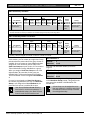
Keypad Programming of Phone #
D1255
1. Refer to Figure 1 on page 7 to access Keypad
Programming and navigate to the PHONE
NUMBERS option.
2. At the PHONE 1 - 4 prompt, enter the phone
number you wish to configure and press [ENT].
The current phone number shows.
If the current phone number is longer
than 20 characters, use the [PREV] and
[NEXT] keys to scroll to view the
additional characters.
3. Press [ENT] to change the phone number.
4. The [PREV] button acts as a [Backspace] key and
the [COMMAND] key scrolls through special
characters. Press [PREV] to delete the characters
of the phone number, and then enter the new
phone number. Press [COMMAND] to cycle
through the special dialing characters {*, #, C, D},
then press [NEXT] to choose a character.
5. Press [ENT] to save the phone number.
6. When the keypad reads PARAMETER SAVED,
your selection has been configured.
D1260
1. Refer to Figure 2 on page 8 to access Keypad
Programming and navigate to the Phone
Numbers option and press the corresponding
softkey.
2. At the Phone (1-4) prompt, enter the phone
number you wish to configure and press [ENTER].
The current phone number shows.
If the current phone number is longer
than 20 characters, the Previous and
Next softkeys appear. Use the softkeys to
scroll to view the additional characters.
3. Press the Edit softkey to change the phone
number.
4. The Pause (3 sec pause - "C") and DT Detect
(Dial Tone Detect - "D") softkeys enter special
characters. The Backspace softkey allows you to
erase characters. The Clear softkey allows you to
clear the entire phone number. The [COMMAND]
and [ENTER] keys allow you to enter an * or a #.
Use the softkeys, the number buttons, and the
[COMMAND] and [ENTER] keys on the keypad to
enter the new phone number.
5. Press the Save softkey.
When the keypad reads Parameter Saved, your
selection has been configured.
Bosch Security Systems, Inc. | 10/11 | F01U170807-02
D9412GV3/D7412GV3 | Program Entry Guide | 2.0
2.2
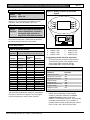
Phone Parameters
The program items in this category describe panelwide characteristics for telephone dialing, receiver
format, and supervision.
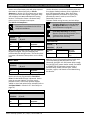
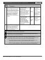
Phone # Format
Default:
Modem IIIa2
Selection:
Modem IIIa2 or Contact ID
Modem IIIa2
Modem IIIa2 Communication Format
Contact ID
ANSI-SIA Contact ID
Panel and Area Wide Parameters
Point/User Flag
Default:
Yes
Selection:
Yes or No
Yes
The control panel sends a flag with
each report telling the D6500 or
D6600 to convert point numbers and
User ID numbers to COMEX format.
Refer to Table 5 and Table 6 for
conversion information. When this
parameter is programmed Yes,
points and User ID numbers are
converted, regardless of the
programming of the D6500 or D6600
Receiver for output to the computer
system. Refer to Appendix C in the
Conettix D6600/D6100
Receiver/Gateway Computer
Interface Manual (P/N: 4998122703).
No
The control panel does not send the
flag. The D6500 or D6600 outputs
point numbers as 001 to 247 (rather
than 100 to 732) and User ID
numbers as 000 to 249 (rather than
000 to F08), as indicated in Table 5
and Table 6.
Central Station Receiver Format for Transmission
of Reports: Modem format provides many reporting
advantages over the Contact ID format. Refer to the
D6500 Report Directory (P/N: 74-04651-001) for
more information about the effect of reporting
formats.
Reports identify points as 001 through 247 and
passcode User ID codes as 000 through 249 at the
D6500 or D6600 Receiver (unless Point/User Flag is
programmed Yes; refer to the Point/User Flag
prompt in this section). When reporting point events,
Modem IIIa2 Communication Format also sends point
text to the D6500 or D6600 as programmed in Point
Assignments.
Keypad Programming of Phone # Format
D1255
1. Refer to Figure 1 on page 7 to access Keypad
Programming and navigate to the PHONE
PARAMETERS option.
2. At the PHONE 1 - 4 prompt, enter the phone
route number you wish to configure and press
[ENT].
3. Press [NEXT] or [PREV] to toggle between
Contact ID and ModemIIIa2 and press [ENT] to
select the desired phone format.
When the keypad reads PARAMETER SAVED, your
selection has been configured.
D1260
1. Refer to Figure 2 on page 8 to access Keypad
Programming and navigate to the Phone
Parameters option and press the corresponding
softkey.
2. At the Phone (1-4) prompt, enter the phone route
number you wish to configure and press
[ENTER]. The current configuration shows.
3. Press the Edit softkey to change the phone
format.
4. Select the softkey for the option to which you
wish to change. Press the Save softkey
When the keypad reads Parameter Saved, your
selection has been configured.
Bosch Security Systems, Inc. | 10/11 | F01U170807-02
EN | 14
This program item determines how point and User ID
numbers are presented at the D6500 or D6600
display, printer, and computer RS-232 output.
When Phone # Format is Yes, the control panel
sends expanded Bosch Modem IIIa2 Communication
Format reports to the D6500 or D6600. If your central
station data files are not set up for point and User ID
number reporting, you can use this program item to
convert these numbers to COMEX Reports.
When Phone # Format is Yes, the control panel
sends expanded Bosch Modem IIIa2 Communication
Format Reports to the receiver. Point/User Flag
affects Bosch Modem IIIa2 Communication Format
data as shown in Table 5. The Bosch Security
Systems, Inc. D6500 or D6600 Receiver adds the
leading zero in the User ID number with Point/User
Flag programmed No.
D9412GV3/D7412GV3 | Program Entry Guide | 2.0
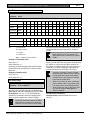
Table 5: Modem IIIa2 Communication Format
Data - User ID Numbers
Point/User Flag
NO
000
001 to 005
006 to 013
014 to 021
022 to 029
030 to 037
038 to 045
046 to 053
054 to 061
062 to 069
070 to 249
Point/User Flag
YES
000
001 to 005
601 to 608
701 to 708
801 to 808
B01 to B08
C01 to C08
D01 to D08
E01 to E08
F01 to F08
000
Table 6: Modem IIIa2 Communication Format
Data – Point Numbers
Point/User Flag
NO
001 to 008
009 to 024
025 to 040
041 to 056
057 to 072
073 to 088
089 to 104
105 to 120
121 to 136
153 to 168
169 to 184
185 to 200
201 to 216
217 to 232
233 to 247
Point/User Flag
YES
100 to 800
101 to 116
201 to 216
301 to 316
401 to 416
501 to 516
601 to 616
701 to 716
801 to 816
217 to 232
317 to 332
417 to 432
517 to 532
617 to 632
717 to 731
Bosch Security Systems, Inc. | 10/11 | F01U170807-02
Panel and Area Wide Parameters
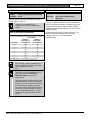
2.2.1
EN | 15
Special Point/User Reporting
Independent Zone Control Notice: When using
Independent Zone Controls (IZC) to send
Opening/Closing Reports by point, do not duplicate
reporting independent point numbers with User ID
Reports (refer to Section 2.1 Passcode or Token
Worksheet on page 82). For example: If an IZC is
connected to Point 8, do not use User ID 8.
D6000: Opening/Closing User ID numbers are
identified at the receiver as zones (same identification
as independent points). Refer to Table 7.
Table 7: D6000 User IDs and Zones
User ID
Number
1
2
3
4
5
6
7
8
Zone
B
C
D
E
F
6
7
8
User ID
Number
91
92
93
04
95
96
Zone
1
2
3
4
5
0
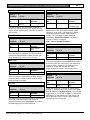
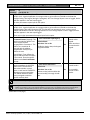
DTMF Dialing
Default:
Yes
Selection:
Yes or No
Yes
Dials the programmed phone
number(s) using DTMF.
No
Pulse dialing only.
Use dual-tone multi-frequency (DTMF) to dial the
central station receiver phone number(s) for event
reports, or to dial the remote programming software
(RPS).
D9412GV3/D7412GV3 | Program Entry Guide | 2.0
Phone Supv Time
Panel and Area Wide Parameters
EN | 16
Buzz on Fail
Default:
0
Default:
No
Selection:
0, 10 to 240
Selection:
Yes or No
0
No phone line supervision.
Yes
10 to 240
Enter the number of seconds (in 10
sec increments) you wish to wait
before indicating trouble. After a
faulted phone line restores, it takes
the same amount of time to start
restoral responses.
Generate panel-wide trouble tones
and display PHONE FAIL # at
keypads when a Phone Fail Event
occurs.
No
Does not generate trouble tones at
keypads when a Phone Fail Event
occurs. PHONE FAIL # still displays.
Phone line trouble responses: Keypads display
SERVC PH LINE # to indicate which phone line
failed. The keypad initiates a trouble tone if Buzz on
Fail is Yes and CC Trouble Tone is Yes.
To meet UL 864 requirements, set this
parameter to Yes.
With dual phone lines (using the D928 Module), the
restored phone line handles all messages regardless
of the phone line’s number.
Phone, Trouble, and Restoral Events report when
they occur. They report also when a Diagnostic
Report is initiated from a keypad or by a Sked.
To meet UL 864 requirements, set this
parameter to a non-zero value.
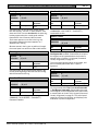
Alarm On Fail
Default:
No
Selection:
Yes or No
Yes
Generate alarm responses when a
phone line fails.
No
Phone failures report as trouble
responses for Area 1 or the account
number associated with Area 1.
To meet UL 864 requirements, set this
parameter to No.
Phone Supv Time must be programmed
to use this feature.
Phone Failure Alarm Responses: The Alarm Bell
relay for Area 1 activates. All Phone Event messages
report as Area 1 and the account number for Area 1.
Bosch Security Systems, Inc. | 10/11 | F01U170807-02
Phone Supv Time must be programmed
to use this feature.
When Buzz on Fail is Yes, users can disable the
resulting trouble tone on individual keypads by setting
CC# Trouble Tone to No.
Two Phone Lines
Default:
No
Selection:
Yes or No
Yes
The D928 Dual Phone Line Module
is installed. The LEDs on the D928
light to indicate primary or secondary
line trouble and COMM FAIL.
No
D928 Dual Phone Line Module is not
installed.
When using two telephone lines, set this
parameter to Yes to meet UL 864
requirements.
Program Phone Supv Time when using
two phone lines.
D9412GV3/D7412GV3 | Program Entry Guide | 2.0
Expand Test Report
Default:
No
Selection:
Yes or No
Yes
Off-normal events listed in Routing
Group Test Reports are reported to
the central station.
No
Off-normal conditions for the events
listed in the Routing Group Test
Reports at test time are not reported.
Use this program item to add system event
information to scheduled Test Reports. Refer to
Section 4.2 Schedules (Skeds) on page 114.
This parameter relates to Sked Function
Code 9 (Test Report) because it allows a
Sked to send Expanded Test Report
information. Expand Test Report does
not affect Sked Function Codes 28
(Expanded Off-Normal Test Report) and
29 (Non-Expanded Off-Normal Test
Report).
Panel and Area Wide Parameters
2.3
EN | 17
Routing
Use routing to select full or partial groups of events to
report to up to eight different destinations (four over
phone, four over network).Routing includes choosing
the most important destination (route number),
reporting the events to a single or multiple destination,
and selecting a backup destination if the events fail.
Event routing can be sent over one of the following:
Standard telephone lines
Local-area network (LAN)
Wide-area network (WAN)
General Packet Radio System (GPRS)
Sending events over a LAN or WAN requires a
network interface module (NIM), such as the DX4020.
Sending events over GPRS requires a special NIM
(ITS-DX4020-G).
2.3.1
Called Party Disconnect
Telephone companies provide called party disconnect
to allow the called party to terminate a call. The called
party must go on hook (hang up) for a fixed interval
before a dial tone is available for a new call. This
interval varies with telephone company equipment.
D9412GV3/D7412GV3 firmware allows for called party
disconnect by adding a 35-sec on-hook interval to the
dial-tone detect function. If the control panel does not
detect a dial tone in 7 sec, it puts the phone line on
hook for 35 sec to activate called party disconnect.
The phone line goes off hook and begins a 7-sec dial
tone detect. If no dial tone is detected, the control
panel dials the number anyway. Each time the number
is dialed, the control panel records this as an attempt.
After ten attempts, the control panel enters
communications failure and Comm Fail Route #
appears on the keypads.
2.3.2
Route Number Groups: Which Has the
Highest Priority?
To program a group, first choose a route number. The
lower the route number, the higher priority that group
has (for example, events reported for Route 1 have a
higher priority than Routes 2, 3, or 4 if each group tries
to send a message at the same time). The priority of
the route numbers becomes important when
programming duplicate reports or choosing the events
you want to report first regardless of the number of
events that must report to multiple groups. Route 1
group primary device is the first destination the control
panel attempts to dial if an event in that group must be
reported. If the control panel is idle, any event
generated for any group starts a dialing sequence.
Bosch Security Systems, Inc. | 10/11 | F01U170807-02
D9412GV3/D7412GV3 | Program Entry Guide | 2.0
2.3.3
Programming Primary and Backup
Destinations
Each route number has an R# Primary Device and
an R# Backup Device. For example, if two phone
numbers are programmed, the R# Primary Device
destination is the phone number that the route group
attempts to dial first. If the R# Primary Device
destination does not connect to the central station
receiver after two dialing attempts, the control panel
dials the R# Backup Device destination.
You can also program the control panel so that the
R# Primary Device or the R# Backup Device uses
an SDI device, such as a Network Interface Module.
With enhanced communications, the R# Primary
Device destination can be either the phone number
or the path number for the SDI device, to which the
route group first attempts to send the event. If the R#
Primary Device destination fails to connect to the
central station receiver after two attempts, the control
panel attempts to connect with the R# Backup
Device destination.
2.3.4
Enhanced Routing
The D9412GV3 and D7412GV3 allow events to be
sent to up to four additional SDI Paths. The network
interface modules (NIMs) connect directly to the SDI
Bus and occupy SDI Address 88 or 92. For additional
information regarding the specific programming
requirements for enhanced communications, refer to
Section 5.5 Programming Path Numbers and IP
Addresses for Enhanced Communications on page
131.
2.3.5
Programming a Duplicate Report
Select Yes for each available route number to allow
an event within a group to send a report to multiple
groups. For instance, if fire alarms are programmed
for Route Group 1 and Route Group 2, a fire alarm
sends a report first to Route Group 1, followed by a
duplicate report to Route Group 2.
2.3.6
Routing Destination Communication
Failures
When the R# Primary Device fails to connect to the
central station receiver after two attempts by phone,
the R# Backup Device phone number will be dialed.
The central station will receive the original event with
a COMM TROUBLE PHONE # = (1, 2, 3, or 4)
message
added. This event does not occur if there is no
backup phone number. If the R# Primary Device is
an SDI Path, the central station receives the original
event with a COMM TROUBLE RG8 SDI## event
modifier. Refer to Table 8 on page 18.
Bosch Security Systems, Inc. | 10/11 | F01U170807-02
Panel and Area Wide Parameters
EN | 18
Table 8: SDI Path Number by Device
Path
SDI 88
SDI 92
1
88
92
2
89
93
3
90
94
4
91
95
When all attempts to both the R# Primary Device and
R# Backup Device fail, a COMM FAIL RG# event is
generated. COMM RESTORE RG# events are
generated when a successful report (via phone or IP)
or a successful poll (via IP) is sent over either route
within the failed Route Group, even if the report is sent
using a different Route Group.
The same COMM TROUBLE conditions occur if the
control panel does not receive a positive
acknowledgement to a poll from the central station
receiver after the configured number of retries. Refer
to Path # Poll Rate on page 132.
2.3.7 Message Prioritization within a Route
Number
The D9412GV3/D7412GV3 Control Panels meet the
digital reporting requirements for UL 864. Fire Alarm
Events have the highest priority and reports are sent
first for each group. Other events are sent in the
following order: Panic, Duress, Medical, Intrusion
Alarm, Supervisory, and all troubles and restorals.
To comply with NFPA and UL 864 ,
program Route 1 to send a report of only
Fire Alarm Events to ensure the fastest
reporting time.
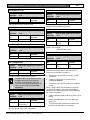
2.3.8
Communication Attempts
The control panel makes up to ten communication
attempts using the primary and backup devices within
a route group. If unsuccessful, it sends a Comm Fail
Report. The communication attempts occur in the
following sequence:
1. Primary device
2. Primary device
3. Backup device
4. Backup device
5. Primary device
6. Backup device
7. Primary device
8. Backup device
9. Primary device
10. Backup device
When only one destination is programmed, the control
panel makes ten attempts to contact that destination.
When reporting via phone, each group takes
approximately 10 min to go into Comm Fail.
D9412GV3/D7412GV3 | Program Entry Guide | 2.0
There are four Route Groups which contain a
selection of event categorizes and individual events.
Each group has a primary and a backup device. The
primary device is the first (most important) destination
used to reach the programmed route within this
group. The backup device is used if the primary
device fails.
R# Primary Device
Default:
No Device
Selection:
No Device, Phone 1..4, SDI ##
Path 1..4
Phone 1
Phone 1 is this group’s primary
destination.
Phone 2
Phone 2 is this group’s primary
destination.
Phone 3
Phone 3 is this group’s primary
destination.
Phone 4
Phone 4 is this group’s primary
destination.
SDI 88 Path 1
Path 1 on SDI 88 is this group's
primary destination.
SDI 88 Path 2
Path 2 on SDI 88 is this group's
primary destination.
SDI 88 Path 3
Path 3 on SDI 88 is this group's
primary destination.
SDI 88 Path 4
Path 4 on SDI 88 is this group's
primary destination.
SDI 92 Path 1
Path 1 on SDI 92 is this group's
primary destination.
SDI 92 Path 2
Path 2 on SDI 92 is this group's
primary destination.
SDI 92 Path 3
Path 3 on SDI 92 is this group's
primary destination.
SDI 92 Path 4
Path 4 on SDI 92 is this group's
primary destination.
To meet UL 864 requirements for
Central Station and Remote Station
applications, program a Primary
Device.
Select the communication device and the primary
destination.
Refer to Section 5.5
Programming Path Numbers
and IP Addresses for Enhanced Communications on
page on page 131 to enable enhanced
communication paths.
Bosch Security Systems, Inc. | 10/11 | F01U170807-02
Panel and Area Wide Parameters
EN | 19
Keypad Programming of R# Primary Device
D1255
1. Refer to Figure 1 on page 7 to access Keypad
Programming and navigate to the
ROUTE GRP 1 - 4 option.
2. At the ROUTE GRP 1 - 4 prompt, enter the route
group number you wish to configure and press
[ENT]. The keypad reads RT GRP 1 PRIMARY,
and then the current configuration (for example,
SDI 88 PATH 4).
3. To change the configuration, press [ENT] when
the current configuration shows, and then press
[NEXT] or [PREV] to scroll through the options, as
listed in R# Primary Device on page 19.
4. When the keypad reads the desired configuration
option, press [ENT] to select it.
When the keypad reads PARAMETER SAVED,
your selection has been configured.
D1260
1. Refer to Figure 2 on page 8 to access Keypad
Programming and navigate to the
Route Group 1 - 4 option.
2. At the Route Group 1 - 4 prompt, enter the route
group number you wish to configure and press
[ENTER]. The keypad reads Rt Group 1 Primary,
and then the current configuration (for example,
SDI 88 PATH 4).
3. To change the configuration, press the Edit
softkey, and then press the Next or the Previous
softkey to scroll through the options, as listed in
R# Primary Device on page 19.
4. When the keypad reads the desired configuration
option, press the Save softkey to select it.
When the keypad reads Parameter Saved, your
selection has been configured.
D9412GV3/D7412GV3 | Program Entry Guide | 2.0
R# Backup Device
Default:
No Device
Selection:
No Device, Phone 1..4, SDI ##
Path 1..4
Phone 1
Phone 1 is this group’s backup
destination if the primary
destination fails.
Phone 2
Phone 2 is this group’s backup
destination if the primary
destination fails.
Phone 3
Phone 3 is this group’s backup
destination if the primary
destination fails.
Phone 4
Phone 4 is this group’s backup
destination if the primary
destination fails.
SDI 88 Path 1
Path 1 on SDI 88 is this group's
backup destination if the primary
destination fails.
SDI 88 Path 2
Path 2 on SDI 88 is this group's
backup destination if the primary
destination fails.
SDI 88 Path 3
Path 3 on SDI 88 is this group's
backup destination if the primary
destination fails.
SDI 88 Path 4
Path 4 on SDI 88 is this group's
backup destination if the primary
destination fails.
SDI 92 Path 1
Path 1 on SDI 92 is this group's
backup destination if the primary
destination fails.
SDI 92 Path 2
Path 2 on SDI 92 is this group's
backup destination if the primary
destination fails.
SDI 92 Path 3
Path 3 on SDI 92 is this group's
backup destination if the primary
destination fails.
SDI 92 Path 4
Path 4 on SDI 92 is this group's
backup destination if the primary
destination fails.
To meet UL 864 requirements for
Central Station and Remote Station
applications, program a Backup
Device.
Select the communication device and the backup
destination. The backup device is used when the
primary device fails to reach the programmed
destination.
Bosch Security Systems, Inc. | 10/11 | F01U170807-02
Panel and Area Wide Parameters
EN | 20
Refer to Section 5.5
Programming Path Numbers
and IP Addresses for Enhanced Communications on
page on page 131 to enable enhanced communication
paths.
Keypad Programming of R# Backup Device
D1255
1. Refer to Figure 1 on page 7 to access Keypad
Programming and navigate to the
ROUTE GRP 1 - 4 option.
2. At the ROUTE GRP 1 - 4 prompt, enter the route
group number you wish to configure and press
[ENT]. The keypad reads RT GRP 1 PRIMARY,
and then the current configuration (for example,
SDI 88 PATH 4).
3. Press [NEXT] to advance to the RT GRP 1
BACKUP option. The Primary device cannot be
set to No Device before setting the Backup
Destination.
4. To change the configuration, press [ENT] when
the current configuration shows, and then press
[NEXT] or [PREV] to scroll through the options, as
listed in R# Backup Device on page 20.
5. When the keypad reads the desired configuration
option, press [ENT] to select it.
When the keypad reads Parameter Saved, your
selection has been configured.
D1260
1. Refer to Figure 2 on page 8 to access Keypad
Programming and navigate to the
Route Group 1 - 4 option.
2. At the Route Group 1 - 4 prompt, enter the route
group number you wish to configure and press
[ENTER]. The keypad reads Rt Group 1 Primary,
and then the current configuration (for example,
SDI 88 PATH 4).
3. Press the Backup softkey. The keypad reads Rt
Group 1 Primary, and then the current
configuration (for example, SDI 88 PATH 4). The
Primary device cannot be set to No Device before
setting the Backup Destination.
4. To change the configuration, press the Edit
softkey, and then press the Next or the Previous
softkey to scroll through the options, as listed in
R# Backup Device on page 20.
5. When the keypad reads the desired configuration
option, press the Save softkey to select it.
When the keypad reads Parameter Saved, your
selection has been configured.
D9412GV3/D7412GV3 | Program Entry Guide | 2.0
2.3.9
Panel and Area Wide Parameters
Route Group Categories
Fire Reports
To meet UL 864 requirements for
Central Station and Remote Station
applications, enable Fire Reports.
Selecting Yes enables a report to be sent when the
event occurs.
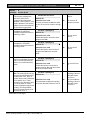
Table 9: Fire Reports
Report
Selections
R# Fire Alarm
R# Fire
Restore
(Alarm)
R# Fire
Missing
R# Fire
Trouble
R# Fire
Supervis
R# Fire
Restore
(T/M/S)
R# Fire
Cancel
R# Fire Sup
Miss
R# Fire Supv
Rest
Yes, No
Yes, No
Report
Description
Fire Event
Fire restoral from
alarm
Yes, No
Missing Fire point
Yes, No
Fire trouble
Yes, No
Fire supervision
Yes, No
Fire restoral from
trouble, missing, or
bypass
Canceled fire alarm
Yes, No
Yes, No
Yes, No
Fire supervisory
missing
Restorals from Fire
Supervision
EN | 21
Burglar Reports
Select Yes to send a report when the event occurs.
Refer to Table 10 on page 21.
Table 10: Burglar Reports
Report
Selections
Report Description
R# Alarm
R# Burg
Restore
Yes, No
Yes, No
R# Duress
R# Missing
Alarm
R# Usr Code
Tmpr
R# Trouble
Report
R# Missing
Trbl
R# Non Fire
Suprv
R# Pt Bus
Fail
R# Pt Bus
Rstl
R# Non Fire
Cncl
R# Alarm
Restore
R# Sup
Missing
R# Unverified
Evt
Yes, No
Yes, No
Burglar Alarm Event
Non-fire restoral from
trouble, missing, or
supervisory
Duress
Missing Alarm point
Yes, No
User code tamper
Yes, No
Trouble Event
Yes, No
Missing Trouble
Event
Non-fire Supervision
Event
Point bus failure
Yes, No
Yes, No
Yes, No
Yes, No
Yes, No
Yes, No
Yes, No
Restoral of point bus
after failure
Canceled non-fire
alarm
Non-fire restoral from
alarm
Supervisory missing
Unverified Events for
Cross Points
R# Unverified Evt is sent when a single
point programmed in Cross Point Group
faults into an alarm condition, then
restores before the Cross Point Time
elapses.
R# Unverified Evt encompasses both
Fire and Non-fire points, but is not related
to the A# Verify Time used for smoke
detectors.
The GV3 Series control panels log a
Ground Fault Event as Trouble Point 256.
Restoral Reports are not sent if the
control panel resets after a point is
bypassed and then unbypassed. This is
true for both Fire and Non-fire points.
Bosch Security Systems, Inc. | 10/11 | F01U170807-02
D9412GV3/D7412GV3 | Program Entry Guide | 2.0
Selecting Yes enables a report to be sent when the
event occurs.
Table 11: User Reports
Selections
R# Point
Bypass
R# Forced
Point
R# Point
Open
R# Point
Close
R# Forced
Arm
R# Fail To
Open
R# Fail To
Close
R# Ext Clos
Tm
R# Opening
Report
R# Forced
Close
R# Closing
Report
R# FC
Perimeter Inst
Yes, No
Report
Description
Point Bypass Event
Yes, No
Forced Point Event
Yes, No
Yes, No
Point Opening
Event
Point Closing Event
Yes, No
Point Force Armed
Yes, No
Fail to Open Event
Yes, No
Fail to Close Event
Yes, No
Extend Close Time
Event
Opening Events
R# FC
Perimeter
Delay
R# Perimeter
Inst Arm
R# Perimeter
Delay Arm
R# Send User
Text
Yes, No
Yes, No
Yes, No
Yes, No
Yes, No
Yes, No
To meet UL 864 requirements for
Central Station and Remote Station
applications, enable Test Reports.
Sending Test Reports
Report
Yes, No
EN | 22
Test Reports
User Reports
Yes, No
Panel and Area Wide Parameters
Point Forced Close
Event
Closing Events
Forced Close
Perimeter Instant
Armed Event
Forced Close
Perimeter Delay
Armed Event
Perimeter Instant
Armed Event
Perimeter Delay
Armed Event
User text
Automatic: To send a single Test Report (R# Test
Report) automatically, enable Sked Function Code #9
(Test Report) in the Skeds section of the program.
Refer to Table 12.
Manual: To send a single Test Report manually, enter
[COMMAND][4][1] at the keypad. Refer to the Send
Report prompt on page 62.
To expand this Test Report to include any off-normal
point condition or other off-normal system conditions,
Expand Test Report (refer to page 14) must be
programmed Yes. Refer to the footnotes with Table 13
on page 24 for a list of event types that are included in
an expanded test report. Additionally, the expanded
test report includes Summary Fire Supervisory,
Summary Fire Fault, Summary Controlled Point Fault,
and Summary Point Device Fault conditions.
The control panel can generate an Expanded OffNormal Test Report by using Sked Function Code 28
or a Non-Expanded Off-Normal Test Report using
Sked Function Code 29. To generate this event, one
or more points must be in an off-normal state at the
time the Sked executes. Expanded Off-Normal Test
Reports include the Off Normal Test Report Event as
well as a panel-wide summary of off-normal point and
system conditions. Non-Expanded Off-Normal Test
Report Events are sent only when a point is in the offnormal state but sends only the Off-Normal Test
Report Event.
Sending Status Reports
Automatic: To send a Status Report automatically
that includes the events shown in the footnotes in
Table 12, enable Sked Function Code #10 in the
Skeds section of the program.
Manual: To send a Status Report manually that
includes the events shown in the footnotes in Table
12, enter [COMMAND][4][2] at the keypad. Refer to
the Send Report prompt on page 62.
Sending off-normal conditions as a Status Report
following a Test Report is required by some
automation systems. Sending off-normal conditions as
a Non-status Report that follows a Test Report is
required for other automation systems.
An off-normal condition is any point that is missing,
trouble, supervisory, or in alarm. Also, points not
cleared at the keypad report as off-normal.
Bosch Security Systems, Inc. | 10/11 | F01U170807-02
D9412GV3/D7412GV3 | Program Entry Guide | 2.0
Report
Selections
R# S: Alarm1
R# S: Trouble1
R# S:
Supervised2
R# Status
Report
R# S: Open1
R# S: Close1
R# Test Report
R# S:
Perimeter Inst1
R# S:
Perimeter
Delay1
R# S: Fire
Supv2
R# S: Fire
Alarm3
R# S: Fire Trbl2
Yes, No
Yes, No
Yes, No
Report
Description
Status Alarm
Status Trouble
Status Supervised
Yes, No
Status
Yes, No
Yes, No
Yes, No
Yes, No
Status Open
Status Close
Test
Status Perimeter
Instant Arm
Status Perimeter
Delay Arm
R# S: Msng
Fire2
R# S:
MsngBurgTr2
R# S:
MsngBurgAl2
R# S:
FireSpMsng2
Yes, No
Yes, No
Yes, No
Yes, No
Yes, No
Yes, No
Yes, No
R# S:
SuperMsng2
Yes, No
R# S:
DrLeftOpen2
Yes, No
EN | 23
Diagnostics Reports
Table 12: Test Reports
Yes, No
Panel and Area Wide Parameters
Status Fire
Supervision
Status Fire Alarm
Report
Status Fire
Trouble
Status Fire
Missing
Status Burg
Missing Trouble
Status Burg
Missing Alarm
Status Fire
Supervision
Missing
Status Non-fire
Supervision
Missing
Status Door Left
Open
1
Information about this condition is sent with a Status
Report.
2
Information about this condition is sent as S: Trouble
Event with a Status Report.
3
Information about this condition is sent as S: Alarm
Event with a Status Report.
Bosch Security Systems, Inc. | 10/11 | F01U170807-02
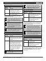
Selecting Yes enables sending a report when the
event occurs. If the off-normal state of the events
indicated by footnote 1 in Table 13 on page 24 still
exists, the events report when a Test Report is
enabled and Expanded Test Report is programmed
Yes. Refer to the Test Reports sub-prompt in Section
2.3.8 Communication Attempts on page 18.
D9412GV3/D7412GV3 | Program Entry Guide | 2.0
Selections
1
Yes, No
R# SDI Dev Restl
Yes, No
R# Watchdog
Rset
R#
ParaChksmFail
Yes, No
R# SDI Dev Fail
Yes, No
R# Reboot
R# Ph Line Fail
Yes, No
Yes, No
1
R# Ph Line Rstl
R# AC Fail
Yes, No
1, 2
Yes, No
R# AC Restorl 2
Yes, No
Report
Description
SDI device
failure
Restoral of SDI
device failure
Watchdog
Reset Event
Parameter
checksum
failure
Reboot Event
Failure of phone
line
Restoral of
phone line after
failure
Failure of AC
power to control
panel
Restoral of AC
power to control
panel after
failure
1, 2
Yes, No
Battery Missing
Detection Event
R# Battery Low
1, 2
Yes, No
R# Battery Rstl
2
Yes, No
Low battery
power
Restoral of
battery power to
control panel
after Missing or
Low Event
R# Batt Missing
R# Rt Comm Fail
1,
Yes, No
3
R# Rt Comm Rstl
Yes, No
EN | 24
Table 13: Diagnostic Reports (Continued)
Table 13: Diagnostic Reports
Report
Panel and Area Wide Parameters
Failure to send
report to
specific route
Restoral of
communication
to specific route
after a failure
Bosch Security Systems, Inc. | 10/11 | F01U170807-02
Report
Selections
R# Rt Comm Rstl
Yes, No
R# Checksum Fail
Yes, No
R# Network Fail
4
Yes, No
4
R# Network Rest
4
R# Network Cond
Yes, No
Yes, No
Report
Description
Restoral of
communication
to specific
route after a
failure
Checksum Fail
Event
Failure of
network
Restoral of
network
Condition of
network
1
This event is included in the Expanded Test Report
when an off-normal condition exists.
2
To meet UL 864 requirements for Central Station and
Remote Station applications, enable AC Fail, Battery
Missing, Low Battery, Battery Restoral, and AC
Restoral reports.
3
This event covers Comm Fail Route Group and Comm
Fail Phone. If enabled, both events are sent; if
disabled, neither event is sent.
4
This event is reserved for future use.
Enable Rt Comm Fail and Rt Comm
Restore in only one route group.
Relay Reports
Selecting Yes enables sending a report when the
event occurs.
Table 14: Relay Reports
Report
Selections
R# Sensor
Reset
R# Relay Set
R# Relay
Reset
Yes, No
Yes, No
Yes, No
Report
Description
Sensor Reset
Event
Relay Set Event
Relay Reset Event
D9412GV3/D7412GV3 | Program Entry Guide | 2.0
When activating an on-board relay using
remote automation software, the
D9412GV3 and D7412GV3 Control
Panels log and print the resulting event
as:
Relay 250 (Relay A)
Relay 251 (Relay B)
Relay 252 (Relay C)
Auto Function Reports
The following prompts support customized routing of
Auto Function Reports. Selecting Yes enables a
report to be sent when the event occurs.
Table 15: Auto-Function Reports
Report
R# Sked
Executed
R# Sked
Changed
R# Execute
Fail
Selections
Yes, No
Yes, No
Yes, No
Report Description
Sked Executed
Event
Sked Changed
Event
Fail to Execute
Event
RPS Reports
Selecting Yes enables sending a report when the
RPS Passcode Event occurs.
"RPS Access Fail" might indicate a
wrong RPS passcode when
communicating with the control panel,
or a valid RPS session was abnormally
terminated. "Remote Reset" indicates a
Reset command was issued from RPS.
"Fail to Call RPS" indicates that control
panel called RPS, but was unable to
connect.
Bosch Security Systems, Inc. | 10/11 | F01U170807-02
Panel and Area Wide Parameters
EN | 25
Table 16: RPS Reports
Report
R# Log
Threshold
R# Log
Overflow
R# Para
Changed
R# RPS OK
Selections
Yes, No
Yes, No
Yes, No
Yes, No
R# RPS Fail
Yes, No
R# Remote
Reset
R# Program
OK
R# Program
Fail
Yes, No
Yes, No
Yes, No
Report Description
Event log threshold
reached
Log is full, old events
are overwritten
RPS Parameter
Change Event
Successful RPS
Access Event
Failed Access RPS
Event
Remote Reset Event
Successful Local
Programming Event
Failed Local
Programming Event
D9412GV3/D7412GV3 | Program Entry Guide | 2.0
Panel and Area Wide Parameters
User Chng Reports
Point Reports
Selecting Yes enables a report to be sent when the
event occurs.
Report
Selections
R# Service Start
Yes, No
R# Service End
Yes, No
R# Fire Walk St
Yes, No
R# Fire Walk End
Yes, No
R# Walk Test St
Yes, No
Yes, No
R# Extra Point
Yes, No
R# Send Point
1
Text
R# RF Low Bat
Yes, No
R# RF Low Bat
Res
Yes, No
1
Yes, No
Selecting Yes enables a report to be sent when the
event occurs.
Table 18: User Change Reports
Table 17: Point Reports
R# Walk Test End
EN | 26
Report
Description
Reorts Service
Walk Test Start
Event
Service Walk
Test End Event
Fire Walk Start
Event
Fire Walk End
Event
Walk Test Start
Event for Walk
Test and
Invisible Walk
Test
Walk Test End
Event for Walk
Test and
Invisible Walk
Test
Extra Point
Event
Point Text
Low battery
conditions for
RF points
Low battery
restoral
conditions for
RF points
Point text is always transmitted when using
network applications.
Bosch Security Systems, Inc. | 10/11 | F01U170807-02
Report
Selections
R# Date
Changed
R# Time
Changed
R# Delete
1
User
R# User Code
Chg
R# Area
Watch
R# Card
Assigned
R# Change
Level
Yes, No
Report
Description
Date Change Event
Yes, No
Time Change Event
Yes, No
Delete User Code
Event
Yes, No
User Passcode Add
or Change Event
Start and end of
area watch
Card Assigned to
User Event
Access Control
Level Change
Event
1
Yes, No
Yes, No
Yes, No
With R# Delete User Events, the control panel
always uses the account number from Area 1.
D9412GV3/D7412GV3 | Program Entry Guide | 2.0
Access Reports
Selecting Yes enables a report to be sent when the
event occurs.
Access Granted, No Entry, Request to
Enter (RTE) and Request to Exit (REX)
Events can be enabled or disabled by
each D9210B.
Table 19: Access Reports
Report
R# Access
Granted
R# No Entry
R# Door Lt
Open
R# Cycle
Door
R# Door
Unlocked
R# Door
Secure
R# Door
Request
R# Door
Locked
Selections
Yes, No
Yes, No
Report Description
Access Granted
Event
No Entry Event
Door Left Open
Event
Open Door Event
Yes, No
Unlock Door Event
Yes, No
Secure Door Event
Yes, No
RTE or REX Event
Yes, No
Locked Door Event
Yes, No
Yes, No
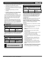
2.3.10 Event Priority
Table 20 on page 27 shows the description of each
event, its priority, and event number.
Bosch Security Systems, Inc. | 10/11 | F01U170807-02
Panel and Area Wide Parameters
EN | 27
Table 20:Event Descriptions, Priorities, and
Numbers
Event Description
Fire Alarm
Fire Alarm Restoral
Fire Missing
Fire Trouble
Fire Supervision
Fire Restoral (after Tbl, Msg,
Bypass)
Fire Cancel
Fire Supervision Missing
Fire Supervision Restore
Alarm Report
Duress
Missing Alarm
User Code Tamper
Trouble Report
Missing Trouble
Non-Fire Supervision
Point Bus Fail
Point Bus Restoral
Non-Fire Cancel
Alarm Restore
Supervision Missing
Unverified Event
Point Bypass/Command Bypass
Forced Point
Point Opening
Point Closing
Was Force Armed
Fail To Open
Fail To Close
Extend Close Time
Opening Report
Forced Close
Closing Report
Event
Priority
001
005
005
005
005
005
Event
Number
011
014
013
012
124
015
004
005
005
003
002
006
008
006
008
006
006
006
004
006
008
006
007
007
008
008
007
008
008
008
008
007
008
027
146
123
016
004
019
055
017
020
078
024
091
045
026
147
169
007
008
021
022
034
040
041
044
047
048
050
D9412GV3/D7412GV3 | Program Entry Guide | 2.0
Table 20: Event Descriptions, Priorities, and
Numbers (Continued)
Event Description
Forced Close Perimeter Instant
Forced Close Perimeter Delay
Perimeter Instant Armed
Perimeter Delay Armed
Send User Text
S: Alarm
S: Trouble
S: Supervision
Status Report
S: Open
S: Close
Test Report
S: Perimeter Instant
S: Perimeter Delay
S: Fire Supervision
S: Fire Alarm
S: Fire Trouble
S: Missing Fire (Trouble)
S: Missing Burglary ((Trouble)
S: Missing Burglary (Alarm)
S: Fire Supervision Missing
S: Burglary Supervision Missing
S: Door Left Open
SDI Device Failure*
SDI Device Restoral*
Watchdog Reset
Parameter Checksum Fail
Reboot
Phone Line Fail
Phone Line Restoral
AC Failure
AC Restoral
Battery Missing
Battery Low
Battery Restoral
Route Comm Fail
Route Comm Restore
Checksum Fail
Sensor Reset
Relay Set
Relay Reset
Sked Executed
Sked Changed
Fail to Execute
Event Log Threshold
Event Log Overflow
Event
Priority
007
007
008
008
n/a
n/a
n/a
n/a
008
n/a
n/a
008
n/a
n/a
n/a
n/a
n/a
n/a
n/a
n/a
n/a
n/a
n/a
004
008
004
n/a
008
004
008
004
008
004
004
008
004
008
n/a
007
007
007
007
007
008
008
008
Event
Number
084
085
088
089
n/a
n/a
n/a
n/a
035
n/a
n/a
051
n/a
n/a
n/a
n/a
n/a
n/a
n/a
n/a
n/a
n/a
n/a
070
071
077
n/a
082
068
069
072
073
074
075
076
066
067
n/a
031
032
033
057
058
151
052
053
0
Bosch Security Systems, Inc. | 10/11 | F01U170807-02
Panel and Area Wide Parameters
EN | 28
Table 20: Event Descriptions, Priorities, and
Numbers (Continued)
Event Description
Parameters Changed
RPS Access OK
RPS Access Fail
Remote Reset
Program Access OK
Program Access Fail
Service Start
Service End
Fire Walk Start
Fire Walk End
Walk Test Start
Walk Test End
Extra Point
Send Point Text
RF Low Battery
RF Battery Restore
Date Changed
Time Changed
Delete User
User Code Change
Area Watch
Card Assigned
Change Level
Access Granted
No Entry
Door Left Open
Cycle Door
Door Unlocked
Door Secure
Door Request
Door Locked
User Alarm COMMAND 7
User Alarm COMMAND 9
Event
Priority
008
008
008
008
n/a
n/a
008
008
008
008
008
008
008
n/a
006
006
008
008
008
008
008
008
007
008
008
008
008
008
008
008
008
002
002
Event
Number
054
064
065
079
n/a
n/a
029
030
036
037
038
039
023
n/a
093
094
059
060
090
056
042
110
061
003
115
116
112
113
114
117
145
005
006
D9412GV3/D7412GV3 | Program Entry Guide | 2.0
2.4
Panel and Area Wide Parameters
Power Supervision
For the following items to be true, AC
Fail/Restoral Report must be
programmed as Yes and AC Tag Along
must be programmed as No.
AC Fail Time
Default:
1:00
Selection:
0:01 to 90:00
Program the amount of time that AC power must be
off before the control panel responds to the AC
failure. The response to restoral of AC power is
delayed for the same amount of time. The control
panel always monitors AC. The response to this
prompt is the actuation of the relay programmed in
the Panel-Wide Relays prompt AC Failure (refer to
Section 2.12.2 Panel-Wide Relays on page 81) and
the AC Fail report enabled by the AC Fail/Restoral
Report prompt. Local annunciation of an AC failure is
controlled by the AC Fail Display prompt.
UL 864 requirements, Section 50.2.1.b
states: “A trouble signal shall be
transmitted for remote station, central
station, and proprietary-type protected
premises units after a delay of between
60 and 180 min.
Exception: Products are not prohibited
from providing capability of selecting
that the primary power failure trouble
signal transmission be delayed other
time periods, including no delay,
provided the 60 – 180 min delay is also
included.”
To meet UL 864 requirements, program
AC Fail Time with 1:00. Always check
with the Authority Having Jurisdiction for
local requirements.
Resend AC Fail
Default:
No Response
Selection:
No Response, 6 hrs, 12 Hrs
No
Response
Only send the AC Fail report upon
failure.
6 hr
Send AC Fail report upon failure and
every 6 hours after this while the
failure persists.
12 hr
Send AC Fail report upon failure and
every 12 hours after this while the
failure persists.
This prompt controls the repeated transmission of the
AC Failure report to the central station while the fault
persists. AC Fail/Restoral Report must be set to
Yes, and AC Tag Along must be set to No for this
feature to work.
Bosch Security Systems, Inc. | 10/11 | F01U170807-02
EN | 29
To eliminate AC Reporting, AC Tag
Along and AC Fail/Restoral Report
must be programmed as No.
AC Fail Display
Default:
60 sec
Selection:
10 to 300 sec (in 5-sec
increments)
Program the length of time the AC power must be off
before the message SERVC AC FAIL shows on the
keypads. The response to restoral of AC power is
delayed for the same amount of time.
AC Fail/Restoral Report
Default:
No
Selection:
Yes or No
Yes
Send AC Fail and AC Restoral
Reports.
No
Does not send AC Fail and AC
Restoral Reports.
AC Power Supervision Reports are sent to the central
station and local printer at the time programmed for
AC Fail Time.
AC Tag Along
Default:
Yes
Selection:
Yes or No
Yes
Send AC messages as tag along
events.
No
Do not send AC messages as tag
along events.
Send AC Reports only if any other event occurs while
AC is off-normal.
If AC Tag Along is set to Yes and a
subsequent event is generated, the AC
Fail Event is sent first, before sending
any subsequent events.
D9412GV3/D7412GV3 | Program Entry Guide | 2.0
AC Tag Along is required for NFPA
and UL 864 Commercial Fire systems.
Be sure to program AC Fail/Restoral
Report as No if AC Tag Along is
programmed Yes.
AC/Battery Buzz
No
Selection:
Yes or No
Yes
Initiates panel-wide trouble tone at
all keypads.
No
Does not initiate panel-wide trouble
tone at keypads
Initiates a panel-wide trouble tone at keypads when
AC fails or battery is low or missing. This program
item does not prevent the SERVC AC FAIL or
SERVC BATT LOW displays.
To comply with NFPA standards and
UL 864 requirements for Commercial Fire
systems, program this item as Yes.
If annunciating panel-wide troubles at a
keypad with CC# Scope set to Panel
Wide is undesirable, set CC# Trouble
Tone to No. Refer to Section 2.9 Keypad
(Command Center) on page 50 for
keypad configurations.
Bat Fail/Restoral Report
Default:
Yes
Selection:
Yes or No
Battery Failure and Restoral Reports are
sent to the central station.
Modem
Reports
No
2.5
EN | 30
Printer Parameters
Up to three D9131A Parallel Printer Interface Modules
can be connected to the D9412GV3’s (one printer for
the D7412GV3’s) SDI bus. Each printer is identified by
an address of 17, 18, or 19. Options are available for
Routing Reports and area assignments.
Printer Address
Default:
Yes
Panel and Area Wide Parameters
Default:
17
Selection:
17, 18, or 19 (only 17 is available
for the D7412GV3)
Enter the printer address you are programming.
P## Area Assign
Default:
1
Selection:
1 to 32 for D9412GV3
1 to 8 for D7412GV3
Assign an area to the printer programmed in Printer
Address.
P## Supervised
Default:
No
Selection:
Yes or No
Yes
Only one printer can be installed for
this P## SDI address.
No
More than one unsupervised printer
can be installed using this P## SDI
address and the same address DIP
switch setting.
Supervise this SDI address. Generate Trouble SDI ##
Reports and local trouble annunciation if a problem
occurs with this printer or the SDI bus.
Unsupervised printers sharing the same
address setting print the same text.
Missing or
shorted
BATTERY
MISSING
Discharged
below 12.1
VDC
BATTERY LOW
Battery Failure and Restoral Reports are not
sent to the central station.
To comply with NFPA standards and
UL 864 requirements for Commercial Fire
systems, program this item as Yes.
Bosch Security Systems, Inc. | 10/11 | F01U170807-02
Trouble SDI ## Reports are always
reported as Area 1, Account 1 Events
regardless of where the SDI device is
assigned.
When P## Supervised is set to Yes and
all Printer Event Groups (such as P##
Fire Events, P## Burglar Event, or P##
Usr Chng Evt) are set to No, the control
panel does not generate Trouble SDI ##
Reports for the printer if the D9131A
becomes disconnected.
D9412GV3/D7412GV3 | Program Entry Guide | 2.0
P## Scope
Panel and Area Wide Parameters
EN | 31
P## Fire Events
Default:
No Printer
Default:
Refer to the program record sheet
Selection:
No Printer, Area, Account, Panel
Wide, Custom
Selection:
Yes or No
Yes
Panel
Wide
Printer prints all designated events
that occur panel-wide. A panel-wide
printer can cross account boundaries.
All events in this group print at
assigned printer.
No
No events in this group print at
assigned printer.
Account
Printer prints all designated events
that occur within any area with the
same account number in which this
printer is assigned.
Area
Printer prints all designated events
that occur in the area to which this
printer is assigned.
Custom
Printer prints all events occurring in
areas programmed Yes for this
prompt regardless of any boundary
restrictions.
No Printer
No printer installed at this address. If
a printer is connected, data does not
print.
P## A1 [through A#] in Scope
Default:
No
Selection:
Yes or No
Yes
Include Area # Events in the scope of
this printer.
No
Does not include Area # Events in
the scope of this printer.
Only available if P## Scope is programmed Custom.
This program item determines if events occurring in
an area print at this printer.
Refer to the report tables in Section 2.3
Routing on page 17 to identify the events
that print. Events programmed as No in
Routing still print at the local printer.
Individual events within the report group
cannot be suppressed for events printed
at the local printer.
Use this prompt to determine whether these events
print at assigned printer.
P## Burglar Event
Default:
Refer to the program record sheet
Selection:
Yes or No
P## Access Event
Default:
Refer to the program record sheet
Selection:
Yes or No
P## User Event
Default:
Refer to the program record sheet
Selection:
Yes or No
P## Test Event
Default:
Refer to the program record sheet
Selection:
Yes or No
P## Diag Event
Default:
Refer to the program record sheet
Selection:
Yes or No
P## Auto Functions Event
Default:
Refer to the program record sheet
Selection:
Yes or No
P## RPS Event
Default:
Refer to the program record sheet
Selection:
Yes or No
P## Relay Event
Bosch Security Systems, Inc. | 10/11 | F01U170807-02
Default:
Refer to the program record sheet
Selection:
Yes or No
D9412GV3/D7412GV3 | Program Entry Guide | 2.0
P## Point Event
Default:
Refer to the program record sheet
Selection:
Yes or No
P## Usr Chng Evt
Default:
Refer to the program record sheet
Selection:
Yes or No
2.6
RPS Parameters
Use these program items to enable remote
programming software (RPS) functions in the control
panel using the on-board phone connection or a
Network Interface Module. Refer to Section 5.4 SDI
RPS Parameters on page 126 for more information
on these types of remote programming.
2.6.1
Uploading and Downloading Reports
If the control panel is programmed to send reports in
ModemIIIa2 reporting format, when RPS contacts the
control panel and the passcode is incorrect, the
control panel sends an RPS Access Fail Report to
the central station receiver. RPS Access Fail might
indicate a wrong RPS passcode when
communicating with the control panel, or a valid RPS
session was abnormally terminated.
RPS ACCESS OK is sent according to phone routing
when a Disconnect command is entered from RPS to
terminate the call.
When a Reset Panel is used to terminate the call, a
Remote Reset Report is sent to the central station
receiver, and an RPS ACCESS OK is placed into the
control panel’s event log. Reports in the event log
that were not sent before the Reset Panel are never
sent to the central station receiver.
When RPS programming changes parameters, a
Parameters Changed Report is sent to the central
station receiver. If any programming changes are
made, perform a Reset-bye.
When RPS contacts the control panel, the RPS
passcode and DataLock code are verified. If the
control panel’s passcode matches and the DataLock
code does not, the control panel still generates a
RPS Access OK Event; however, the session ends
immediately.
To prevent the control panel from answering the
telephone automatically, enter 0 in the Answer
Armed and Answer Disarmed prompts in this
section.
Panel and Area Wide Parameters
EN | 32
2.6.2 Log Threshold Reports
When the event log reaches the percentage
configured in Log % Full and the control panel is
properly configured, it will contact Unattended RPS
over phone or network.
If communication with RPS is unsuccessful, or if not
properly configured, the control panel generates Log
Threshold and Fail to Call RPS events.
Fail to Call RPS Events are logged only locally. If
properly configured, the control panel makes multiple
attempts to reach RPS before sending the reports. To
enable transmission of the events when the Log
Threshold is reached, set a valid phone number in
RPS Ph (refer to RPS Phone # on page 35)or set a
valid IP address in RPS IP (refer to RPS IP Address #
on page 130).
2.6.3
Panel Initiated Unattended RPS
The control panel will automatically contact
Unattended RPS when the Log Threshold is reached
or when the Contact RPS Sked function is executed.
When the control panel is attempting to contact
Unattended RPS, it will start with two attempts. If the
control panel does not reach RPS on the first two
attempts, it waits 10 min then tries six more times with
a 10-min interval between each attempt. One hour
after the last failed attempt, the control panel starts
contacting Unattended RPS again. It makes two more
attempts then waits 10 min and tries six more times
with 10-min intervals between each attempt before
generating a Fail to Call RPS Report and abandoning
the effort.
If network RPS is configured, then any control panel
initiated attempt to contact Unattended RPS will be
over network. If network RPS is not configured, then
contact will be attempted over the phone.
Manually Initiated Unattended RPS: If properly
configured, an authorized user can initiate contact with
Unattended RPS by entering [COMMAND][4][3] and
advancing the menu until RPS via Phone or RPS
via Network shows. After proceeding through one
of these options, the control panel makes one attempt
to contact Unattended RPS.
RPS Passcode
Default:
999999
Selection:
0 to 9, A to F
(six characters required)
Enter six characters. Do not use a space in the
passcode.
The control panel verifies the remote programming
software at the central station has valid access before
connecting using the RPS passcode.
Bosch Security Systems, Inc. | 10/11 | F01U170807-02
D9412GV3/D7412GV3 | Program Entry Guide | 2.0
Keypad Programming of RPS Passcode
D1255
1. Refer to Figure 1 on page 7 to access Keypad
Programming and navigate to the RPS
PASSCODE option. The keypad shows the
currently configured passcode.
2. Press [ENT] to change the passcode. An invisible
editing cursor is enabled.
3. The [PREV] button acts as a [Backspace] key.
The [COMMAND] key allows you to cycle though
the special passcode characters (A, B, C, D, E,
F); the [NEXT] key selects the passcode
character. Press [PREV] to delete the characters
of the passcode, and then enter the passcode.
4. Press [ENT] to save the passcode.
When the keypad reads PARAMETER SAVED,
your selection has been configured.
D1260
1. Refer to Figure 2 on page 8 to access Keypad
Programming and navigate to the RPS
Parameters option and press [ENTER]. The
keypad shows the currently configured RPS
Passcode.
2. Press the Edit softkey to change the passcode.
An editing cursor is enabled.
3. Use the softkeys and the number buttons on the
keypad to enter the new passcode. The
Backspace softkey allows you to erase
characters. The Clear softkey allows you to clear
the entire passcode. When entering a letter
character, press the letter’s softkey to select it.
The Previous and Next softkeys advance
through the letter characters (A, B, C, D, E, F).
4. Press the Save softkey to save the passcode.
When the keypad reads Parameter Saved, your
selection has been configured.
Log % Full
Default:
0
Selection:
0 to 99
When the event log reaches the percentage full
indicated in this prompt, the control panel logs a Log
Threshold event. If Contact RPS if Log % Full is set
to Yes, then the control panel will attempt to contact
Unattended RPS and copy the event log before
messages are overwritten.
A setting of 0 disables the Log Threshold and Log
Overflow Events. These events are not entered in the
log or reported to the central station receiver or the
local printer.
Bosch Security Systems, Inc. | 10/11 | F01U170807-02
Panel and Area Wide Parameters
EN | 33
The control panel continues to log events after the Log
Threshold Report is sent. When the event log reaches
100%, a Log Overflow event is generated and the
oldest events are overwritten.
The control panel does not call RPS again until it
downloads the log and the Log % Full percentage is
reached. These events are also sent to the control
panel’s event log and to the local printer(s) if installed.
The Log Overflow Event is not sent to
the central station unless Expanded
Test Report is programmed Yes.
Failure to program the RPS telephone
number and the RPS IP address number
results in a FAIL TO CALL RPS trouble
event sent to the central station when the
log threshold is reached. Refer to the
RPS Phone # prompt on page 35 for
information about programming the RPS
telephone number. Refer to the RPS IP
Address # prompt on page 130 for
information about enabling network RPS.
Contact RPS if Log % Full
Default:
No
Selection:
Yes or No
Yes
Directs the control panel to
automatically communicate with
Unattended RPS over network or
phone when Log Threshold is
reached.
No
The control panel will not
automatically contact RPS when Log
Threshold is reached.
When the event log reaches the percentage full
indicated by Log % Full the Log Threshold event is
put in the event log. If this prompt is set to Yes and
either the RPS IP address or RPS Phone # are
programmed, then the control panel will attempt to
contact Unattended RPS as described in Section 2.6.3
Panel Initiated Unattended RPS on page 32.
D9412GV3/D7412GV3 | Program Entry Guide | 2.0
Panel and Area Wide Parameters
RPS Call Back
Default:
No
Selection:
Yes or No
Yes
When the control panel hears the
correct RPS passcode, it hangs up
the phone, seizes the phone line,
then dials the programmed RPS
phone number (refer to the RPS Ph
prompt on page 35). This ensures
that the control panel only
communicates with RPS units
connected to the programmed phone
number.
If the call is answered manually, the
call back must be initiated manually.
No
The RPS session starts immediately.
No call back is required. The control
panel can engage in RPS sessions
when called from any phone number
and a proper RPS passcode is
identified.
This function allows the control panel, after it verifies
the RPS passcode, to provide an additional level of
security by hanging up and dialing the RPS phone
number at the central station before allowing any
upload or download.
When using the RPS Call Back feature,
be sure to program the character “C” as
the last digit in the RPS phone number
when using DTMF Dialing.
RPS Line Monitor
Default:
Yes
Selection:
Yes or No
Yes
Allows the control panel to
communicate with RPS after the
answering machine answers the
phone.
No
Use No if the control panel does not
share the phone line with an
answering machine.
This program item enables a control panel that
shares a phone line with an answering machine to
communicate with RPS at the central station, even
though the answering machine answers the phone.
You must program Answer Armed or Answer
Disarmed. The control panel must be in the correct
armed state.
Bosch Security Systems, Inc. | 10/11 | F01U170807-02
EN | 34
Program this item No if it causes false
seizures of the phone line or if you do
not use RPS. This indicates that a
device using the same frequency tone is
also using the phone line to which the
control panel is connected.
If RPS Call Back is programmed Yes,
the control panel hangs up the phone
after the RPS tone and a proper RPS
passcode is identified. It then calls the
RPS phone number.
Answer Armed
Default:
Refer to the program record sheet
Selection:
0 to 15
0
No answer.
1 to 15
The control panel answers the phone
after the specified number of rings
when all areas are master armed.
Set the telephone ring counter to answer when all
areas are master armed. If any area in the control
panel is perimeter armed or disarmed, the Answer
Disarmed ring counter is used.
For the purposes of answering the RPS
phone call, the control panel considers
Perimeter Armed a disarmed state..
Answer Disarmed
Default:
Refer to the program record sheet
Selection:
0 to 15
0
No answer.
1 to 15
The control panel answers the
phone after the specified number of
rings when any area in the system is
in a perimeter armed or disarmed
state.
Set telephone ring counter to answer when any area is
in a perimeter armed or disarmed state.
For the purposes of answering the RPS
phone call, the control panel considers
Perimeter Armed a disarmed state.
D9412GV3/D7412GV3 | Program Entry Guide | 2.0
RPS Phone #
Default:
Blank
Selection:
Blank or up to 24 characters
Blank
Control panel does not dial a phone
number for RPS.
1 to 24
characters
Enter up to 24 characters to define
dialing characteristics.
This is the phone number the control panel dials to
contact RPS. Refer to Section 2.6.1 on page 32 for
instructions on configuring special phone number
digits to detect dial-tone detect and to pause dialing.
The control panel dials this number when any of the
following events occur:
Log % Full threshold is achieved.
If Log % Full is programmed with a
value (1 to 99) and an RPS phone
number or RPS IP address are
programmed, the control panel attempts
to communicate with Unattended RPS
when the log threshold is reached.
The control panel is contacted by RPS and RPS
Call Back is programmed Yes.
The user enters COMMAND 43 and selects the
call RPS option from the menu. On the D1255:
1. Press [COMAND][4][3].
2. Press [NEXT] until RPS via Phone? appears,
then press [ENTER].
The control panel tries to contact RPS
only once using this method.
Refer to Section 5.4 SDI RPS Parameters on page
126 for other connection methods.
Refer to Phone # in Section 2.1 Phone
on page 12 for descriptions of special
programming values for the RPS Phone
number.
Panel and Area Wide Parameters
EN | 35
Keypad Programming of RPS PHONE #
D1255
1. Refer to Figure 1 on page 7 to access Keypad
Programming and navigate to the RPS
PARAMETERS option. Press [ENT]. The keypad
shows the RPS PASSCODE option and the
currently configured passcode.
2. Press [NEXT] to advance to the RPS PHONE
NUMBER option.
3. The keypad shows the currently configured phone
number. Press [ENT] to edit the phone number.
4. The [PREV] button acts as a [Backspace] key.
Press [PREV] to delete the characters of the
phone number, and then enter the new phone
number.
5. Press [ENT] to save the phone number.
When the keypad reads PARAMETER SAVED,
your selection has been configured.
D1260
1. Refer to Figure 2 on page 8 to access Keypad
Programming and navigate to the RPS
Parameters option. Press [ENTER]. The keypad
shows the RPS Passcode and the currently
configured passcode.
2. Press Phone Number softkey.
3. The keypad shows the currently configured phone
number.
4. Press the Edit softkey to change the phone
number.
5. The Pause and DT Detect (Dialtone Detect)
softkeys enter special characters. The Backspace
softkey allows you to erase characters. The Clear
softkey allows you to clear the entire phone
number. The [COMMAND] and [ENTER] keys
allow you to enter an * or a #. Use the softkeys,
the number buttons, and the [COMMAND] and
[ENTER] keys on the keypad to enter the new
phone number.
6. Press [ENT] to save the phone number.
When the keypad reads Parameter Saved, your
selection has been configured.
RPS Modem Speed
Default:
1200
Selection:
300, 1200, 2400
Select the baud rate for RPS-to-control panel
communication when using a PSTN connection.
Bosch Security Systems, Inc. | 10/11 | F01U170807-02
D9412GV3/D7412GV3 | Program Entry Guide | 2.0
2.7
Miscellaneous
Duress Type
Panel and Area Wide Parameters
EN | 36
Cancel Report
Default:
No
Default:
0
Selection:
Yes or No
Selection:
0, 1, 2, or 3
Yes
Send Cancel and Fire Cancel
Reports according to routing.
No
Do not send Cancel and Fire Cancel
Reports.
0
1
Do not send a duress event with any
passcode.
Increase the last digit by 1 to generate an
alarm. For example, if the passcode is 6123,
6124 activates a duress alarm.
If the last digit of the passcode is 0, a duress
alarm occurs when the user enters 1 as the
last digit of the passcode.
If the last digit of the passcode is 9, a duress
alarm occurs when the user enters 0 as the
last digit of the passcode.
2
Increase the last digit by 2 to generate an
alarm. For example, if the passcode is 6123,
6125 activates a duress alarm.
If the last digit of the passcode is 8, a duress
alarm occurs when the user enters 0 as the
last digit of the passcode.
If the last digit of the passcode is 9, a duress
alarm occurs when the user enters 1 as the
last digit of the passcode.
3
Send a Duress event when any Passcode with
L# Send Duress set to Yes is entered.
This program item determines when a passcode
entry with L# Send Duress authority should produce
a duress alarm.
Duress is enabled in Area Parameters by
setting A# Duress Enable to Yes.
The duress alarm activates when a user
enters the duress passcode followed by
the termination keys ([ESC] or [ENT]).
For SIA CP-01 Compliance
Duress Type must be set to 3.
Bosch Security Systems, Inc. | 10/11 | F01U170807-02
A Cancel and Fire Cancel Report is created when a
passcode is entered to silence an Alarm Bell or a Fire
Bell before the bell time expires.
For SIA CP-01 Compliance
This prompt must be set to Yes.
Call for Service Text
Default:
Refer to the program record sheet
Selection:
Twenty alphanumeric characters
Enter the text to display on a D1260 series keypad
when the control panel is out of service.
2.8
Area Parameters
This programming module contains three
programming categories: Area Parameters, Bell
Parameters, and Open/Close Options.
2.8.1
Area Parameters
Enter the area number you are programming.
Area# Area On
Default:
Yes (Area 1 only)
Selection:
Yes or No
Yes
Enable area.
No
Disable area.
Use this program item to enable or disable the area
specified.
Refer to Keypad Programming of Area # On and
Area# Account Number on page 37.
D9412GV3/D7412GV3 | Program Entry Guide | 2.0
Area 1 must be enabled:
System events such as power and
phone supervision do not send a
report correctly if Area 1 is disabled.
When programmed No, points
assigned to this area do not generate
events, show at the keypad when
arming and disarming, or send status
reports. All user authority in this area
is turned off while the area is
disabled.
To meet UL 864 requirements, set A#
Area On to Yes.
Area# Account Number
Default:
0000
Selection:
For Modem and Contact ID (fourdigit account numbers): 0000 to
9999,
BBBB to FFFF
For Modem (ten-digit account
numbers): 0000000000 to
9999999999, BBBBBBBBBB to
FFFFFFFFFF
Determines the account number for this area. An
account number must be assigned to each active
area.
Account numbers are used to group areas together.
Each area can have a different account number, or
several areas can share the same account number.
The control panel uses the account number as a
reference for arming and keypad text displays.
Contact ID: Only the last four digits are sent.
Modem IIIa2: Enter a four-digit or ten-digit number.
Keypad Programming of Area # On and Area#
Account Number
D1255
1. Refer to Figure 1 on page 7 to access Keypad
Programming and navigate to the AREA
PARAMETERS option. Press [ENT].
2. The keypad reads AREA NUM 1 – 32 (1 – 8 for
the D7412GV3).
3. Enter the area number you wish to configure and
press [ENT]. The current area status shows (for
example, AREA 1 ON: YES).
4. Press [ENT] to change the area’s status.
5. Press the [PREV] or [NEXT] button to toggle
between YES and NO, and then press [ENT]
when the desired configuration option shows.
Bosch Security Systems, Inc. | 10/11 | F01U170807-02
Panel and Area Wide Parameters
EN | 37
When the keypad reads PARAMETER SAVED, your
selection is configured.
6. When the keypad reads AREA STATUS, press
[NEXT] to advance to the A# ACCOUNT
NUMBER option. The keypad shows the currently
configured account number.
7. Press [ENT] to change the account number.
8. The [PREV] button acts as a [Backspace] key.
The [COMMAND] key cycles though the special
account number characters (B, C, D, E, F);
[NEXT] select the account number character.
Press [PREV] to delete the characters of the
account number and then enter the new account
number.
9. Press [ENT] to save the changes.
When the keypad reads Parameter Saved, your
selection is configured.
D1260
1. Refer to Figure 2 on page 8 to access Keypad
Programming and navigate to the Area
Parameters option. Press [ENT].
2. The keypad reads Area Number 1 – 8.
3. Enter the area number you wish to configure and
press [Enter]. The current area status shows (for
example, Area 1 On: Yes).
4. Press the Edit softkey to change the area’s status.
5. Press the Yes or No softkey, and then press the
Save softkey to save the changes.
When the keypad reads Parameter Saved, your
selection is configured.
6. When the keypad reads Area Status, press the
Account Number softkey. The keypad shows the
currently configured account number.
7. Press the Edit softkey to change the account
number.
8. Use the softkeys and the number buttons on the
keypad to enter the new account number. The
Backspace softkey allows you to erase
characters. The Clear softkey allows you to clear
the entire account number. When entering a letter
character, press the letter's softkey to select it.
The Previous and Next softkeys advance through
the letter characters (A, B, C, D, E, F).
9. Press the Save softkey to save the changes.
When the keypad reads Parameter Saved, your
selection is configured.
A# Force Arm/Bypass Max
Default:
1
Selection:
0 to 99
Specify the maximum number of combined Controlled
points that can be faulted or bypassed when arming
this area.
D9412GV3/D7412GV3 | Program Entry Guide | 2.0
Refer to the prompts P## Force Arm Returnable
and P## Bypass Returnable in Section 3.2 Point
Responses on page 91 for returning a point to the
system when the point returns to normal or when the
area is disarmed.
Users can bypass more points than the
number entered here during the
disarmed state. It is only when the user
attempts to Bypass Arm an area (or
areas) that this restriction is enforced.
Panel and Area Wide Parameters
A# Auto Watch
Default:
No
Selection:
Yes or No
Yes
When the area is disarmed, Watch
Mode turns on automatically.
No
When the area is disarmed, Watch
Mode must be turned on or off
manually.
A# Delay Restorals
Default:
No
Selection:
Yes or No
Yes
Point Restoral Report is not sent until
the bell time expires or user
acknowledges alarm condition.
No
Restoral Reports are sent when point
restores, regardless of bell time.
A# Exit Tone
Default:
Yes
Selection:
Yes or No
Sounds an exit tone during exit delay at all keypads
assigned to this area.
You can turn off exit tones for individual
keypads by programming the
appropriate CC# 1 to 8 as No in CC#
Exit Tone.
A# Exit Dly Time
Default:
60
Selection:
0 to 600 ( in 5 sec increments)
Exit delay time for this area when Master Exit or
Perimeter Exit arming.
Points programmed for instant alarm
response generate alarms immediately,
even during exit delay. To avoid instant
alarms on points adjacent to the
perimeter when leaving the area,
program P## Type as 3 (Interior
Follower).
For SIA CP-01 Compliance
The Exit Delay Time must be between 45 sec and
255 sec.
Bosch Security Systems, Inc. | 10/11 | F01U170807-02
EN | 38
Controlled points must be programmed
as P## Watch Point to generate a
watch tone.
A# Verify Time
Default:
60
Selection:
10 to 60 (in 1-sec increments)
Use alarm verification with smoke detectors to reduce
the number of false fire alarms. When Verify Time is
programmed, the control panel can check smoke
detector point activations before generating alarm
signals.
Do not enable the Cross Point feature
in point indexes designated for Fire
points.
Check with your authority having
jurisdiction (AHJ) to determine the
maximum verification time allowed.
Points are programmed individually to activate the
verification feature. Refer to Section 3.1 Point Index
on page 87. Any resettable Fire point can activate
alarm verification for the area to which it is assigned.
Use separate area alarm-verification relays.
To enable alarm verification on a point, program Point
Index, Fire Point, Alarm Verify, and Resettable as
Yes.
When an Alarm Verification point senses an alarm, the
control panel automatically removes power to all
Resettable points connected to the area’s Reset
Sensors relay. The sensor reset removes power to the
sensors for the amount of time programmed in Verify
Time. When power is reapplied, a 60-sec confirmation
window begins. If the detector is still in alarm and
experiences another alarm during the confirmation
window, or a different Resettable Verification point in
the area senses an alarm, an alarm occurs.
Example: Verify Time is set for 20 sec. The alarm
verification cycle starts when the detector senses
smoke or fire. No report occurs.
D9412GV3/D7412GV3 | Program Entry Guide | 2.0
When the detector senses smoke or fire, the area’s
sensor reset relay interrupts power to points
connected to it for the time in Verify Time.
Panel and Area Wide Parameters
EN | 39
When power restores to the points, the 60-sec
confirmation window starts. If any detector, reset
during the verification time, experiences another alarm
during the confirmation window, an alarm occurs. If no
activity occurs during this period, no alarm occurs and
the verification window ends. If a Verification point
senses another alarm after the window ends, a new
verification cycle begins. Refer to Table 21 on page
39 for an example of Verify Time.
To meet UL 864 requirements, set A#
Verify Time to 60 sec.
Table 21: Verify Time
Verification
Point Activation
Example: Total
Cycle time 80 sec
Verify Time/Reset
Sensors
Power removed,
ignore activity
20 sec
A# Duress Enable
Default:
No
Selection:
Yes or No
Yes
Enable Duress alarm for this area.
No
Disable Duress alarm for this area.
Refer to Duress Type in Section 2.7 Miscellaneous
on page 36 for an explanation of duress.
For SIA CP-01 Compliance:
A# Duress Enable must be set to Yes.
The passcode you normally use for
duress is not valid in an area with A#
Duress Enable set to No.
If a passcode with the appropriate
L# Disarm authority is used to duress
disarm an area with A# Duress Enable
set to No, NO AUTHORITY appears in
the display. Also, if the keypad display is
moved to an area with A# Duress
Enable set to No using
[COMMAND][5][0], a valid duress disarm
passcode does not send a duress report.
Bosch Security Systems, Inc. | 10/11 | F01U170807-02
60 sec Confirmation
Generate alarm if
additional activity
received.
60 sec
Restart Alarm
Verification Cycle if
an Alarm Verification
point activates.
D9412GV3/D7412GV3 | Program Entry Guide | 2.0
Panel and Area Wide Parameters
EN | 40
A# Area Type
Default:
Regular
Selection:
Regular, Master, Associate, or Shared
Regular
Arms or disarms as an independent area.
Master
Does not allow arming for this area unless all associate areas with the same A# account
number are master exit delay armed or master armed. CHK AREA displays if the associate
areas are not armed. Exception: RPS allows master areas to be armed without all associate
areas being in the armed state.
A master area can be disarmed regardless of the armed state of the other areas in the account.
Multiple master areas can be programmed in a single account.
CC# Scope affects master arming.
Area: When arming a master area that has CC# Scope set to Area for all
keypads, all associate areas within the same account must first be armed
independently by other means.
Panel Wide or Account Wide: When arming a master area from a keypad
with CC# Scope set to Panel Wide or Account Wide, all associate areas
enters exit delay as soon as the master area is armed. If there is a shared
area within the same account, it begins its exit delay after all associate
areas are armed.
Using the arming sked (S## Function 1) requires that you first use an
arming sked to arm the associate areas before using an arming sked to
arm the master area. Arming master areas with RPS, Keyswitch, or Auto
Close parameters (refer to Section 2.8.4 Open/Close Options on page 43)
occurs before all associate areas are armed
Associate
Allows arming and disarming regardless of the armed state of the other areas with the same A#
account number. Use this area type with a master area and associate it by using the same
account number.
Keypads assigned to associate areas, when used with shared areas, must
have CC# Scope programmed.
Shared
Shared areas:
do not associate to other areas by account number
are armed when all Associate areas in the control panel are Master Delay armed
are disarmed when at least one Associate area in the control panel is not Master Delay
armed
cannot be individually armed using a passcode, key switch, token or card, sked, or RPS
Arming commands intended for a shared area must be executed on a
keypad with Panel Wide scope by a user with appropriate authority in all
Associate areas. Shared areas associate with all Associate areas
regardless of their account assignments.
Bosch Security Systems, Inc. | 10/11 | F01U170807-02
D9412GV3/D7412GV3 | Program Entry Guide | 2.0
2.8.2
Shared-Area Characteristics
Arming a Shared Area
A shared area arms automatically when all associate
areas are armed. As soon as the last associate area
is armed, the shared area automatically begins its
arming sequence. Passcode, key switch, subcontrols, or RPS cannot arm shared areas. To
display faulted points at associate areas, the shared
and associate areas must have the same account
number.
Disarming a Shared Area
Shared areas automatically disarm when any
associate area in the control panel is disarmed.
Passcode, tokens, cards, key switch, sub-controls, or
RPS cannot disarm shared areas.
Shared Area Arming Sequence
When shared areas automatically begin to arm, the
arming is based on the A# Exit Dly Time is based on
the A# Exit Dly Time of the Shared Area.
Shared Area Not Ready
If a point is faulted in the shared area, CHK AREA
appears on the associate keypad that is arming the
last associate area. Associate area keypads can
show faults from shared areas as long as the shared
areas fall within the scope of the associate area.
Force Arming a Shared Area
When CHK AREA appears, press [ESC] to show
FORCE ARM at the associate keypad. Pressing
[ENTER] force arms the shared area if:
the user has authority to bypass points,
the point is bypassable, and
the number of faulted points does not exceed the
force arm maximum amount for the shared area.
Remember to include the shared area
in the associate area’s scope.
Viewing Shared Area Armed Status
View Area Status can be used from a keypad outside
of the shared area to view the shared area’s armed
state.
Panel and Area Wide Parameters
EN | 41
Silencing Sounders in the Shared Area
Silence shared area alarms and troubles from any
keypad.
To silence sounders, the user needs an authority
level assigned to the shared area. If the user also has
the authority to arm or disarm the area, then
ALREADY ARMED or ALREADY DISARMED
momentarily appears.
Access Control Readers Assigned to the Shared
Area
The shared area restarts the exit delay sequence
allowing a user to walk to an associate area and
disarm. If the token or card reader assigned to the
shared area includes any associate area in the D##
CC# Scope (in the access control section), both the
associate area and shared area disarms when the
token or card is presented. (Refer to Access Control
Readers Assigned to the Shared Area on page 41.)
Closing Reports for Shared Areas
If Closing Reports for shared areas are needed,
assign passcodes a valid authority level in the shared
area.
2.8.3
Bell Parameters
The D9412GV3 and the D7412GV3 have two main
types of annunciation: Fire Bell and Burg Bell. Both
Fire and Burg Bells share the same terminal
(Terminal 6) on the control panel as shipped from the
factory.
If a simultaneous Fire Bell and Burg Bell occur, the
Fire Bell takes precedence over the Burg Bell
regardless of which relay or terminal output they
share.
When the Fire and Burg Bells share the same output
and a Fire Bell occurs while the Burg Bell is ringing,
the Fire Bell pattern overrides the Burg Bell pattern.
At the end of the fire time, the burg pattern resumes.
When the Fire and Burg Bells share the same output
and a Burg Bell occurs while a Fire Bell sounds, the
control panel waits until the Fire time expires before
starting the Burg Bell.
Either a single bell (panel-wide) or a number of bells
(area-wide) can be used on the control panel. For
programming these applications, refer to Section
2.12.1 Area Relays on page 79.
When both Fire and Burg Bells occur simultaneously
and a user enters a valid passcode, a Fire Cancel
Report for the fire alarm and a Cancel Report for the
burg alarm is sent to the central station if Cancel
Reports is programmed Yes.
Bosch Security Systems, Inc. | 10/11 | F01U170807-02
D9412GV3/D7412GV3 | Program Entry Guide | 2.0
Panel and Area Wide Parameters
Select the bell pattern this area uses to signal an
alarm on a Fire point.
A# Fire Time
Default:
6 min
Selection:
1 min to 90 min
Enter the number of minutes the bell rings for Fire
Alarm points. The relay activated for this time is
programmed in A# Fire Bell in Area Relays.
The bell output begins as soon as the fire alarm
occurs. It shuts off the bell when the programmed
number of minutes expires.
When an alarm occurs on two Fire
points sharing the same relay, the bell
pattern of the most recent fire event
takes precedence.
A# Burg Time
Default:
6 min
Selection:
1 to 90 min (in one-minute
increments)
If programmed for 1 min, the output can be anywhere
from 0 to 60 sec of bell time. Program Fire Time for 2
min or more to ensure you have ample output time.
To meet UL 864 requirements, program
A# Fire Time for at least 5 min. Check
with your AHJ to determine the
appropriate bell time for your
geographical area.
A# Fire Pattern
Default:
Pulse
Selection:
Steady, Pulse, CaStnd, TmCod3
Steady
Steady Output
Pulse
Pulse March Time
120 beats per minute, at an even
tempo
CaStnd
California Standard
10 sec On + 5 sec Off + 10 sec On +
5 sec Off. This sequence repeats
until bell time expires.
TmCod3
EN | 42
Temporal Code 3
0.5 sec On, 0.5 sec Off, 0.5 sec On,
0.5 sec Off, 0.5 sec On, 1.5 sec Off;
pattern repeats. This sequence
repeats for a minimum of 3 min and
with a ± 10% tolerance.
Bosch Security Systems, Inc. | 10/11 | F01U170807-02
4 min for UL
5 min for ULC
Enter the number of minutes the bell rings for
Burglary Alarm points. The relay activated for this
time is programmed in A# Alarm Bell in Area Relays.
The bell output begins as soon as the burglary alarm
occurs. It shuts off the bell when the programmed
number of minutes expires.
When the control panel’s internal clock begins a new
minute, it considers the first minute expired. Program
Burg Time for 2 min or more.
Check with your AHJ to determine the
appropriate bell time for your
geographical area.
For SIA CP-01 Compliance:
A# Burg Time must be 6 min or more.
A# Burg Pattern
Default:
Steady
Selection:
Steady, Pulse, CaStnd, TmCod3
Select the bell pattern this area uses to signal an
alarm on a Non-fire point.
D9412GV3/D7412GV3 | Program Entry Guide | 2.0
A# Single Ring
Default:
No
Selection:
Yes or No
Yes
One bell output per arming period.
After one alarm, alarms on any Nonfire points in the same area cannot
restart the bell until the armed state
changes. An alarm on a different
point in same area restarts bell
output.
No
Restart bell output with each alarm
event.
Determines if an alarm from a non-fire point can
restart the alarm bell time with each Alarm Event, or
only start alarm output once per arming period.
Panel and Area Wide Parameters
Bell Test After Confirmation
In areas that send Opening and Closing Reports, the
Bell Test occurs after the control panel sends the
Closing Report and receives an acknowledgment
from the central station receiver. For proper operation
of the Bell Test after closing confirmation, the
following rules apply:
The control panel must send Opening and
Closing Reports to the central station.
Do not use restricted openings and closings or
Opening and Closing Windows.
Area Armed Confirmation
In areas that do not report opening and closing
activity, the alarm bell relay output for this area
activates for 2 sec after exit time expires.
Multiple Bell Tests occur: When more
than one area is armed at the same time
(such as using the ARM ALL AREAS?
function), the bell rings for 2 sec with a
2 sec pause between each bell activation
if all areas have the same exit delay time
programmed. Otherwise, the Bell Test
occurs as each area arms and it
completes its exit delay time.
This does not silence the keypad alarm bell tone, or
prevent any reports. This feature does not affect Fire
points. Fire points restart bell time with each new
alarm.
If an alarm occurs on a 24-hour point
while the area is disarmed, arming that
area with a key switch does not clear
the A# Single Ring flag.
When areas arm simultaneously and
report to the central station, the Bell
Test occurs as the central station
receiver confirms each area.
Silencing the bell resets A# Single
Ring.
2.8.4
A# Bell Test
Default:
No
Selection:
Yes or No
Yes
Start Bell Test.
No
Do not start Bell Test.
Provides alarm output from the relay programmed at
A# Alarm Bell after the Closing Report is confirmed
or the exit delay time expires.
EN | 43
Open/Close Options
Programming determines if Opening, All Normal
Closing, and Force Arm/Bypass Closing Events are
sent to the remote central station. Without remote
reports, all control panel and area arming (Closing
Events) and disarming (Opening Events) default to
local events.
Use this programming category to determine which
opening and closing supervision characteristics are
needed.
There are three ways to generate reports from the
control panel. You can generate reports by account,
by area, or a combination of both.
Opening and Closing Events are sent
only by users with the proper authority
settings.
Bosch Security Systems, Inc. | 10/11 | F01U170807-02
D9412GV3/D7412GV3 | Program Entry Guide | 2.0
To suppress reports:
Use Opening/Closing Windows to suppress
reports for a specified period of time and then
automatically turn them on again.
Use the Restricted O/C options. A Closing Report
is sent if the user is force arming, sending
duress, or bypass arming. An Opening Report is
sent if the user is disarming during an alarm
condition or unbypasses points when disarming.
If the system is normal, no Opening or Closing
Report is sent.
Panel and Area Wide Parameters
A# Account O/C
Default:
No
Selection:
Yes or No
Yes
Send Opening and Closing Reports
by account.
Use this selection if the control panel
sends reports to an automation
system that cannot interpret multiple
Area Opening and Closing Reports.
An Account Opening Report is
generated when the first area in an
account is opened (disarmed). After
the Account Opening Report is sent,
disarming other areas in the account
does not generate another Account
Opening Report. An Account Closing
Report is generated only when the
last area in an account is closed
(armed). Opening and Closing
Reports for accounts do not contain
any area information.
For the scheduled suppression of
Opening and Closing Reports, refer to
Section 4.1.1 Opening and Closing) to
define Opening and Closing Windows.
Account Opening and Closing Reports
Opening and Closing Reports are sent by account
when the last area in a group of areas with the same
account number(s) is armed.
Area Opening and Closing Reports
Closing Reports are sent for each area as it is armed.
The account number is also sent for each area.
Opening and Closing Windows
affect Account Opening and
Closing Reports: If an account
opening or closing is generated while
an Opening or Closing Window for
this area is in effect, and Disable O/C
in Window is programmed Yes, the
report is not sent. Use the same
opening and closing window times for
all areas sharing the same account
number.
Customizing Account Opening and Closing
Reports
You can eliminate area Opening and Closing Reports
from selected areas in the account by programming
A# Area O/C as No for those areas.
Combination Account and Area Opening and
Closing Reports
To send both account openings and closings, and
individual area openings and closings for all areas in
the account, you must:
Program A# Account O/C as Yes for all areas in
the account.
Program A# Area O/C as Yes for all areas in the
account.
Closing Reports: When areas in the account are
independently armed, each area generates an Area
Closing Report. When the last area is armed, it also
generates an Account Closing Report.
Opening Reports: When the first area in the account
is disarmed, it generates an Account Opening Report
along with an Area Opening Report. When the
remaining areas in the account are disarmed, each
area generates an Area Opening Report.
Area Only Opening Closing Supervision Features
Use these features to supervise opening and closing
activity by area. Auto Close, Fail To Open, and Fail
To Close all work independently of the A# Account
O/C feature. To use these features, program O/C
Windows.
Bosch Security Systems, Inc. | 10/11 | F01U170807-02
EN | 44
No
Do not send Opening and Closing
Reports by account.
Determines if this area generates Account Opening
and Closing Reports. Program this item the same for
all areas in the account.
D9412GV3/D7412GV3 | Program Entry Guide | 2.0
A# Area O/C
Default:
Yes
Selection:
Yes or No
Yes
No
Include the Area # and generate Opening
and Closing Reports for this area when it is
armed.
Do not include the Area # or generate
Opening and Closing Reports for this area.
Determines if the area number and the account
number are reported at arming and disarming. As
long as Account O/C is No, the account number
sends a report when arming this area individually. If
Account O/C is Yes, all areas with the same account
number must also be armed.
An Area Opening Report is generated when each
area is opened (disarmed). An Area Closing Report is
generated when each individual area is closed
(armed).
Do not program this item as Yes if the
control panel reports to an automation
system that cannot interpret multiple Area
Opening and Closing Reports.
Panel and Area Wide Parameters
Determines if opening and closing activity is reported
when it occurs inside an Opening or Closing Window,
as programmed in O/C Windows.
Reports are always logged and printed on a local
printer, if installed.
A# Auto Close
Default:
No
Selection:
Yes or No
Yes
The area automatically master arms at the
end of the Close Window.
When the area is armed automatically, a
Closing Report is sent if the Area or
Account Reports are programmed to do so.
No
Do not automatically arm the area at the
end of the Close Window.
With this program item, the control panel can
automatically master arm the area at the end of the
Closing Window regardless of the previous armed
state.
When an area master arms automatically
at the end of a Close window, the system
disregards the settings in A# Force Arm
Max and P## Bypassable for any faulted
points. The faulted points arm when they
return to normal state.
A# Disable O/C in Window
Default:
Yes
Selection:
Yes or No
Yes
No
Do not send Opening and Closing Reports
to the central station if they occur inside an
active window.
EN | 45
A# Fail to Open
Default:
No
Selection:
Yes or No
If an Opening or Closing Report occurs
outside a window, send it with an early or
late modifier. Refer to Section 4.1.1
Opening and Closing on page 105.
Yes
Fail to Open Report is sent for this
area if the area was not disarmed
when the Opening Window stop time
occurred.
The active window must be a Closing
Window for Closing Reports. It must be an
Opening Window for Opening Reports.
No
Fail to Open Report is not sent for
this area.
Send Opening and Closing Reports to the
central station even when they occur inside
a programmed window. If an opening or
closing occurs outside of the appropriate
window, it reports but does not have an
early or late modifier.
If you want to monitor all opening and
closing activity and use features provided
by Opening and Closing Windows, program
this item as No, and program the
appropriate O/C Windows.
Bosch Security Systems, Inc. | 10/11 | F01U170807-02
Use to determine if a Fail to Open Report is sent for
this area. This can determine if a user failed to
disarm the area before the Opening Window expiring.
Normal Opening and Closing Reports do not need to
be programmed to use this feature.
D9412GV3/D7412GV3 | Program Entry Guide | 2.0
A# Fail to Close
Panel and Area Wide Parameters
EN | 46
A# Restrictd O/C
Default:
No
Default:
No
Selection:
Yes or No
Selection:
Yes or No
Yes
Fail to Close Report is sent for this
area if the area is not armed when
the Closing Window stop time occurs.
Yes
Restrict Opening and Closing
Reports for this area. A# Area O/C
must be programmed Yes to
generate Restricted Opening and
Closing Reports.
Note:
Program an exit delay time in
Exit Dly Time.
No
Note:
If a passcode is not required for
arming or disarming and this item
is Yes, the area sends only
Restricted Opening and Closing
Reports. In this case, Restricted
Reports are sent without User ID.
Fail to Close Report is not sent for
this area.
If Auto Close is programmed
Yes, a Fail to Close Report is
sent because it occurs when the
Closing Window stop time
occurred.
Opening/Closing Window does not
affect this report. Windows do not
prevent sending Restricted Opening
and Closing Reports from being sent.
Early or late designations are not
added to Opening or Closing Reports
when they are sent according to the
rules for Restricted Opening or
Closing Reports.
If Disable O/C in Window is
Yes, the Fail to Close Report is
followed by Closing Late or
Force) Close Late.
This item determines if a Fail to Close Report is sent
for this area. Use to determine if a user failed to arm
the area before the Closing Window expires. Normal
Opening and Closing Reports do not need to be
programmed to use this feature.
No
Do not Restrict Opening and Closing
Reports for this area.
Regardless of programming in
Authority Levels L## Restricted O/C,
reports are not restricted in this area
when this item is programmed as No.
Note:
Was Force Armed and Forced
Close Events can still be sent to
the central station if enabled in
Routing when force arming the
system.
This item determines if this area can restrict Opening
and Closing Report activity.
A Restricted Opening Report refers to the control
panel sending an Area Opening Report only when
the area is disarmed after a non-fire alarm.
A Restricted Closing Report refers to the control
panel sending a Force Closed Report only when the
area was master armed with Controlled points that
were faulted during the arming sequence. The
sequence of reports generated by a restricted closing
is: Was Force Armed, Forced Point, and Force
Closed.
Bosch Security Systems, Inc. | 10/11 | F01U170807-02
D9412GV3/D7412GV3 | Program Entry Guide | 2.0
A# Perimeter O/C
Default:
No
Selection:
Yes or No
Yes
This area can send Perimeter Opening and
Closing Reports.
No
This area cannot send Perimeter Opening
and Closing Reports.
This item determines if this area can send Perimeter
Instant and Perimeter Delay Closing Reports and
normal Opening Reports to the central station.
Opening and Closing Windows do not suppress this
event. Refer to the L## Perimeter O/C prompt on
page 75.
This reporting requires ModemIIIa2
reporting format reporting. Some central
station automation systems cannot
process these reports.
A# Latest Close Time
Default:
00:00
Selection:
00:00 to 24:00
Use to set a Latest Close Time boundary value for
this area. If the Latest Close Time value is non-zero,
the time of day specified with the Extend Close
feature cannot be greater than or equal to this value.
A zero value for A# Latest Close Time disables the
feature for the area.
Example: If A# Latest Close Time is set for 17:30,
the user can extend the close time to as late as
17:29.
This prompt is used only when an O/C Window is
assigned to an area. Make entries in 30-min
increments using a 24-hour format. Use times that
begin on the hour or the half-hour only. For example,
enter 2:30 PM as 14:30. Enter 1:00 AM as 01:00. To
set the Latest Close Time for midnight, use a value of
24:00. The latest close time allowed by the Extend
Close feature is 24:58, because of internal limitations
in the control panel.
The default entry of 00:00 disables the
Latest Close Time feature for this area.
The control panel sets all windows for the next day
when the control panel clock turns to midnight. The
control panel must cross the midnight boundary
before any changes in that default setting occur.
Bosch Security Systems, Inc. | 10/11 | F01U170807-02
Panel and Area Wide Parameters
EN | 47
To extend across midnight, you must use two
windows:
To suppress reports before midnight, use one
window (for example, 20:00 start to 23:59 stop).
To suppress reports immediately after midnight,
use another window (for example, 00:01 start to
02:00 stop).
2.8.5
Arming Features
A# Two Man Rule
Default:
No
Selection:
Yes or No
Yes
Two valid unique passcodes are
required to disarm the area.
No
A single passcode with a valid
authority level can disarm the area.
The D720 Keypad does not support the
Two-Man Rule feature.
Use this parameter when disarming an area that is
Master Armed. After recognizing the first valid
passcode, the system requests a second passcode
to disarm the area. If the entry delay expires before
the entry of a second valid unique passcode, an
alarm condition occurs. This function works only
when you use Passcode Disarm.
When you are disarming an area with A#
Two Man Rule set to Yes, the keypad
waits for the time equal to the A# Exit
Delay Time. If the second passcode is
not entered before the prompt times out,
the rule resets and waits for the first
passcode again.
If the area is already in an alarm
condition, the first valid passcode entered
after the alarm occurs silences the bell
but does not disarm the area. Enter
Code 2 appears on the display. A second
valid unique passcode is necessary to
disarm the area.
This feature is not allowed for use with
SIA CP-01 compliant installations.
Consult the local authority having
jurisdiction (AHJ) for proper usage. Refer
to your control panel’s program entry
guide for programming information.
D9412GV3/D7412GV3 | Program Entry Guide | 2.0
Parameter Setup Requirement:
Two Man Rule can be completed only by entering
two valid unique passcodes with L## Passcode
Disarm authority.
Panel and Area Wide Parameters
EN | 48
When the first digit of the second code is pressed,
the following message appears. As each digit is
pressed, an additional asterisk appears.
To avoid unintended results for the end
user of the system:
Set CC# Scope to Area Wide for
keypads assigned to areas with the
Two Man Rule feature.
Avoid setting the A# Two Man Rule
to Yes in an area where A# Early
Ambush is set to Yes.
Use this feature in banks or other facilities
that might require a higher level of
security to gain access to a vault or other
protected area.
A# Early Ambush
Default:
No
Selection:
Yes or No
Yes
Two valid passcodes are required to
disarm the area within the time period
specified in Early Ambush Timer. The
second valid disarm passcode must
be entered within a time limit. Refer
to Early Ambush Timer on page
137.
D1255 Keypad
After the first valid passcode is entered, the D1255
replaces the scrolling DISARM NOW and the Point
Text display with the SECOND CODE:.display
If the second passcode is not entered
within the time limit, the system
generates a Duress Event based
upon the primary user.
When the user presses the first digit of the second
code, the display changes to SECOND CODE: *.
SECOND CODE: appears for 19 sec. If no digits are
pressed, the display returns to normal and the area
does not disarm. If a second code is entered, the
area disarms and an Opening report is sent with the
User ID of the first user. If the second code entered is
the same as the first code, is invalid, or does not
have L## Disarm authority, the keypad shows NO
AUTHORITY and returns to idle text or entry delay.
D1260 Keypad
In the D1260, after the first valid passcode is entered,
the following message appears for 3 sec.
No
A single passcode with a valid
authority level can disarm the area.
The Early Ambush disarming feature is intended for
use when you disarm an area that is in the Master
Armed state, but it can also be used with the
Perimeter and Instant Armed states. After the first
valid passcode is entered, the area is disarmed and
the keypad displays the disarmed idle text normally.
This function operates only when you use Passcode
Disarm.
If the second valid disarm passcode is entered, the
D1255 Keypad shows CODE 2 VALIDATE and
sounds the Watch Mode tone. Only the Watch Mode
tone appears on the D720 Keypad.
The D1260 Keypad sounds the Watch Mode tone
and the following text appears.
Then the next message appears requesting a second
code.
Bosch Security Systems, Inc. | 10/11 | F01U170807-02
D9412GV3/D7412GV3 | Program Entry Guide | 2.0
Panel and Area Wide Parameters
Parameter Setup Requirement:
To avoid the possibility of false alarms in
Associate areas, do not use the A# Exit
Restart feature in areas with A# Area
Type set to Shared.
The Early Ambush timer can be started and stopped
only by passcodes with the L## Passcode Disarm
authority.
To avoid unintended results for the end
user of the system:
When a keypad is assigned to an area
that has the Early Ambush feature
enabled, set the CC# Scope value to
Area Wide.
If an area has A# Two Man Rule set
to Yes, do not set A# Early Ambush
to Yes.
During an alarm, after the first passcode is entered,
the Early Ambush timer still begins. A Cancel Report
might be generated, depending upon the bell time,
and the keypad displays Alarm Silenced normally. If
the second valid disarm passcode is entered, the
keypads indicate that the second passcode is valid.
Refer to the Secondary Ambush Code prompt on
page 137 for information about the unique behavior
of the two passcodes.
For SIA CP-01 Compliance:
EN | 49
For SIA CP-01 Compliance
This prompt can be set to Yes or No.
A# Arm No Exit
Default:
Yes
Selection:
Yes or No
Yes
Switch the arming state to Perimeter
if no Perimeter Delay point faults
occurred.
No
Keep the area in Master Arm if no
Perimeter Delay point faults
occurred.
This parameter switches the arming state of an area
from Master Armed to Perimeter Armed if no
perimeter points with delay response were activated
during the exit delay time. Only the final armed state
is reported and displayed at the keypads.
The A# Arm No Exit feature does not
operate in areas with A# Area Type set
to Shared.
This feature is not allowed for use with
SIA CP-01 compliant installations.
For SIA CP-01 Compliance:
A# Exit Restart
A# Exit Restart can be set to Yes or No.
A# Exit Warning
Default:
Yes
Selection:
Yes or No
Default:
Yes
Yes
Delay armed points in this area
restart the exit delay timer if violated
during the exit delay time.
Selection:
Yes or No
Yes
Pulse the alarm output for the last 10
sec of the Exit Delay time.
No
Do not pulse the Alarm Bell output
during the Exit Delay time.
No
Delay armed points continue to count
down normally if violated during the
exit delay time.
This feature must be disabled for UL Line
Security/Encryption applications.
When enabled, this feature activates when a
controlled point with delay alarm response changes
from normal to faulted and back to normal during the
exit delay. When activated, if any controlled point in
the same area with delay alarm response is faulted,
the exit delay time restarts. The exit delay continues
until it expires or the area changes arming states.
This operation can occur only once in an arming
cycle.
Bosch Security Systems, Inc. | 10/11 | F01U170807-02
When enabled, the Alarm Bell output pulses on and
off every 2 sec for the remaining 10 sec of the Exit
Delay time.
For SIA CP-01 Compliance
A# Exit Warning must be set to Yes.
D9412GV3/D7412GV3 | Program Entry Guide | 2.0
Panel and Area Wide Parameters
2.9
A# Entry Warning
EN | 50
Keypad (Command Center)
This programming module contains three
programming categories: Cmd Cntr Assignment,
Area Text, and Custom Function.
Default:
Yes
Selection:
Yes or No
Yes
Pulse the alarm output for the last 10
sec of the Entry Delay time.
No
Do not pulse the Alarm Bell output
during the Entry Delay time.
When enabled, the Alarm Bell output pulses on and
off every 2 sec for the remaining 10 sec of the Entry
Delay time.
For SIA CP-01 Compliance
A# Entry Warning must be set to Yes.
2.9.1
Keypad (Command Center) Assignment
This programming category assigns a keypad to an
area and determines if the keypad is supervised. The
keypads are connected to the control panel using a
two-wire serial data interface (SDI) bus.
This bus can support up to sixteen supervised
keypads, each with its own unique keypad address
(CC) and corresponding DIP switch address settings.
If the keypads are not supervised, you can install
multiple keypads with the same DIP switch address
setting for up to 32 unsupervised keypads.
Enhanced keypads (D1260 Series) and standard
keypads (D1255 Series) cannot share the same SDI
Address.
Cmd Center
DIP Switch Setting
SDI Address (CC#)
1
2
3
4
5
6
1
ON
ON
ON
ON
--
ON
2
OFF
ON
ON
ON
--
ON
3
ON
OFF
ON
ON
--
ON
4
OFF
OFF
ON
ON
--
ON
5
ON
ON
OFF
ON
--
ON
6
OFF
ON
OFF
ON
--
ON
7
ON
OFF
OFF
ON
--
ON
8
OFF
OFF
OFF
ON
--
ON
9
ON
ON
ON
OFF
--
ON
10
OFF
ON
ON
OFF
--
ON
11
ON
OFF
ON
OFF
--
ON
12
OFF
OFF
ON
OFF
--
ON
13
ON
ON
OFF
OFF
--
ON
14
OFF
ON
OFF
OFF
--
ON
15
ON
OFF
OFF
OFF
--
ON
16
OFF
OFF
OFF
OFF
--
ON
Enter the keypad (CC) number for the SDI address you are programming. This number corresponds to the DIP
switch address settings shown.
Switch 5: On=Encoding Tone On (default), Off=Encoding Tone Off
The D1255 can be addressed as 1 through 16. The D1260 can be addressed only as 1 – 8.
Bosch Security Systems, Inc. | 10/11 | F01U170807-02
D9412GV3/D7412GV3 | Program Entry Guide | 2.0
CC# Supervised
Default:
Refer to the program record sheet
Selection:
Yes or No
Yes
Only one keypad can be installed for this
CC SDI address.
No
More than one keypad can be installed
using this CC SDI address with the same
address DIP switch setting.
Supervise this SDI address and generate Trouble
SDI Reports and local trouble annunciation if a
problem occurs with this keypad or the SDI bus.
To meet UL 864 requirements, set CC#
Supervised to Yes for the fire
annunciation keypad.
Keypads that share the same address
setting display the same text and emit the
same tones, regardless of which keypad’s
keys are pressed.
Trouble SDI # Reports are always
reported as Area 1, Account 1 Events
regardless of the area the SDI device is
assigned.
Panel and Area Wide Parameters
4. Press [NEXT]. The current keypad type shows
(for example, CC - 1 TYPE ENHANCED: YES).
5. Press [ENT] to change the keypad’s type.
6. Press [NEXT] or [PREV] to toggle to No to
indicate that the D1255 is not an enhanced
keypad, and then press [ENT] to save the
changes.
When the keypad reads PARAMETER SAVED, your
selection has been configured.
D1260
1. Refer to Figure 2 on page 8 to access Keypad
Programming and navigate to the Command
Center option.
2. Press [ENTER]. The CC Num 1 – 16 option
shows.
3. Enter the keypad number you wish to configure
and press [ENTER]. The keypad reads CC#
Scope, and then the current configuration (for
example, Panel Wide).
4. Press the Type softkey. The current keypad type
shows (for example, CC (1) Type Enhanced:
Yes).
5. Press the Edit softkey to change the keypad’s
type.
6. Press the Yes or No softkey, and then press the
Save softkey to save the changes.
When the keypad reads Parameter Saved, your
selection has been configured.
When this prompt is Yes, you cannot
have duplicate DIP switch settings.
Reboot the system to enable a D1260
Series Keypad.
To reboot the system, close and open the
reset switch, labeled “S1 RESET,”
located in the upper right corner of the
control panel.
CC# Enhanced Command Center
Default:
No
Selection:
Yes or No
Yes
This keypad is a D1260 Series
Keypad.
No
This keypad is not a D1260 Series
Keypad.
When a D1260 Series Keypad is installed at this
keypad address, this item must be set to Yes.
Keypad Programming of CC# EnhancCMDCTR
D1255
1. Refer to Figure 1 on page 7 to access Keypad
Programming and navigate to the COMMAND
CENTER option.
2. Press [ENT]. The CC NUM 1 – 16 option shows.
3. Enter the keypad number you wish to configure
and press [ENT]. The keypad reads CC#
SCOPE, and then the current configuration (for
example, PANEL WIDE).
Bosch Security Systems, Inc. | 10/11 | F01U170807-02
EN | 51
CC# Area Assign
Default:
1
Selection:
1 to 32 on D9412GV3
1 to 8 on D7412GV3
Enter the area number where you are installing this
keypad or keypads with this address and the same
DIP switch settings.
D9412GV3/D7412GV3 | Program Entry Guide | 2.0
Panel and Area Wide Parameters
EN | 52
CC# A1 [through A#] in Scope
CC# Scope
Default:
Refer to the program record sheet
Default:
Selection:
Panel Wide, Custom, No Keypad,
Area, and Account
Refer to the preceding important
note
Selection:
Yes or No
Panel
Wide
A panel-wide keypad can view
information and perform Arming and
Disarming functions for all areas in
the control panel. A panel-wide
keypad can cross account
boundaries. This is normally used
with a master area.
Yes
Include this area in the scope of this
keypad.
No
Do not include this area in the scope
of this keypad.
Account
An Account keypad can view
information, and perform Arming and
Disarming functions for all areas with
the same A# Account Number, in
Area Parameters. This is normally
used for an associate area.
Area
An area keypad is restricted to
viewing information and Arming or
Disarming functions for the area to
which it is assigned.
Custom
A custom keypad shows information
and allows arming and disarming for
specific areas you select. (This option
is not available through Keypad
Programming.)
No
Keypad
No keypad installed at this address.
CALL FOR SERVICE display shows,
indicating the control panel is not
polling this address.
This program item is used to define the areas
affected when an arming command is executed on
this keypad, the areas this keypad can view, and the
areas to which this keypad can move.
In applications where keypads include
more than one area, active alarms in
remote areas must be acknowledged
before arming or disarming the local area.
The following prompt is visible only when
you program CC## Scope to Custom. If
you change the keypad scope selection
to Custom from Panel Wide, Account, or
Area, the settings from the previous CC#
Scope selection become the default
settings for the custom parameters in
CC# A1 [through A#] in Scope. Before
exiting from a custom program, check
each area and ensure that it is enabled
and disabled correctly.
Bosch Security Systems, Inc. | 10/11 | F01U170807-02
Determines whether any of the areas and doors are
included in the scope of this keypad for viewing
status, arming or disarming, and controlling doors
from the keypad.
Keypad Programming of CC# Scope
D1255
1. Refer to Figure 1 on page 7 to access Keypad
Programming and navigate to the COMMAND
CENTER option.
2. Press [ENT]. The CC NUM 1 – 16 option shows.
3. Enter the keypad number you wish to configure
and press [ENT]. The keypad reads CC#
SCOPE, and then the current configuration (for
example, PANEL WIDE).
4. To change the configuration, press [ENT] when
the current configuration shows, and then press
[NEXT] or [PREV] to scroll through the options,
as listed in CC# Scope on page 52 .
5. When the keypad reads the desired configuration
option, press [ENT] to select it.
When the keypad reads PARAMETER SAVED,
your selection has been configured.
D1260
1. Refer to Figure 2 on page 8 to access Keypad
Programming and navigate to the Command
Center option.
2. Press [ENTER]. The CC Num 1 – 16 option
shows.
3. Enter the keypad number you wish to configure
and press [ENT]. The keypad reads CC# Scope,
and then the current configuration (for example,
Panel Wide).
4. To change the configuration, press the Edit
softkey, and then press the Next or Previous
sofkeys to scroll through the options, as listed in
CC# Scope on page 52 .
5. When the keypad reads the desired configuration
option, Save to select it.
When the keypad reads Parameter Saved, your
selection has been configured.
D9412GV3/D7412GV3 | Program Entry Guide | 2.0
Panel and Area Wide Parameters
CC# Enter Key Relay
Default:
0
Selection:
0 to 128, A, B, C (0 to 64, A, B, C
for the D7412GV3)
0
The [ENTER] key is not used to
activate a relay.
1 to 128 (64),
A, B, C
Assign the relay number that
activates when [ENTER] is pressed
at this keypad after the user enters
a valid passcode.
The service passcode cannot be used
for the CC# Enter Key Cycle Door
application.
When programmed to activate a relay,
the [ENTER] key cannot be used for
any other function.
Relays used for this function must not
be shared with any other point, sensor
reset, control panel, or bell functions.
Sharing can cause errors in relay
operation.
The door does not cycle if Enter Key
Relay is programmed.
Enter Key Relay: Program the relay number that
activates momentarily for 10 sec when a user enters
a valid passcode and presses the [ENTER] key on
the keypad. Two events are generated when this
function is used: RELAY ### SET with User ID, and
RELAY ### RESET without User ID. The system
logs this action as two events.
Entering a valid code and pressing [ENTER] at a
keypad silences a ringing bell.
Using CC# Enter Key Relay for a low-level
access control strike on a door does not shunt a
point.
When programmed to activate a relay, the
[ENTER] key cannot be used for any
other function.
Relays used for this function must not be
shared with any other point, sensor reset,
control panel, or bell functions. Sharing
can cause errors in relay operation.
CC# Enter Key Cycle Door
Default:
No
Selection:
Yes or No
Yes
The [ENTER] key is used to cycle the
door programmed for CC Assign
Door.
No
The [ENTER] key is not used to cycle
the door.
Enter Key Cycle Door: Program this prompt as Yes
to start the door cycle sequence for the door number
programmed in CC# Assign Door when a user
enters a valid passcode and presses [ENTER]. This
includes shunting the point assigned to the door.
ACCESS GRANTED prints on the local printer and at
the central station receiver, if programmed.
Bosch Security Systems, Inc. | 10/11 | F01U170807-02
EN | 53
9210 NOT READY appears at this
keypad when you press [ENTER] if the
D9210B is not programmed with a D#
Entry Area (in the Access Control
section) or if CC Assign Door does not
have a door number assigned.
CC# Assign Door
Default:
No Door
Selection:
No Door, 1 to 8 on D9412GV3.
(No Door, 1, 2 on D7412GV3)
No
Door
No door controller is assigned for adding
tokens.
1 to 8
The door controller assigned to this keypad
is used to read new tokens when the Add
User Mode is initiated.
If the assigned door remains open and this keypad
has the CC# Close Door Warning Tone set to Yes,
the CLOSE DOOR # message appears on this
keypad.
D9412GV3/D7412GV3 | Program Entry Guide | 2.0
If a door is not programmed for this
prompt and a door is not assigned to
the area using the D# Entry Area in
the Access Control section, 9210 NOT
READY appears at this keypad when
you attempt to add a user. The
message indicates that the control
panel cannot start the Add User Mode
until a door is assigned to this keypad.
Assigning a door to a keypad is not
necessary for the user to control the
door(s) using the Door Control
function. Any door that is active can be
controlled by a user who has the
appropriate door control authority. The
door control functions are available to
a valid user at any keypad with access
to the area where the door is
assigned.
During the Add User Mode, tokens or
cards, door control requests, and
RTE/REX do not function. Put the Door
Mode into an unlocked state before
adding users if there is heavy activity for
this door.
CC# Trouble Tone
Panel and Area Wide Parameters
EN | 54
CC# Entry Tone
Default:
Yes
Selection:
Yes or No
Yes
This keypad sounds entry tones.
No
This keypad does not sound entry
tones.
Determines whether this keypad, or any keypad with
the same address setting, emits the entry delay tone.
Any Delay point within the area scope of this keypad
starts the entry sequence.
This prompt allows you to manage the
tone by keypad. Entry Tone can also be
turned off when programming your P##
Entry Tone off in Point Index.
Assign two CCs to the same area so one
keypad emits the tone and another does
not.
For SIA CP-01 Compliance
CC# Entry Tone can be set to Yes or No.
CC# Exit Tone
Default:
Yes
Default:
Yes
Selection:
Yes or No
Selection:
Yes or No
Yes
This keypad sounds exit tones.
Yes
Panel-wide trouble tones sound and
visual displays show at this keypad.
No
This keypad does not sound exit
tones.
No
Panel-wide troubles do not sound.
Visual displays still show.
Determines whether this keypad, or any keypad with
the same address setting, emits the panel-wide
trouble tones (power, phone, SDI bus, and Zonex
bus).
To meet UL 864 requirements, set CC#
Trouble Tone to Yes.
Panel-wide trouble tones do not include
Point Troubles, Buzz on Fault, or Close
Door Now.
Assign two CCs to the same area so one
keypad emits the tone and another does
not.
Bosch Security Systems, Inc. | 10/11 | F01U170807-02
Determines whether this keypad, or any keypad with
the same address setting, emits the exit delay tone
during the delay arming of an area(s). Any keypad
with a scope to arm this area can initiate the exit tone
sequence.
This prompt allows you to manage the tone by
keypad. Exit Tone can also be turned off when
programming A# Exit Tone in Area Parameters.
The cadence and pitch of the exit tone increase for
the last 10 sec of the exit delay time.
This SIA CP-01 required feature is not
supported on the D720 Series Keypads.
Assign two CCs to the same area so one
keypad emits the tone and another does
not. Set one keypad for CC EXIT TONE =
YES, and one to EXIT TONE = NO.
D9412GV3/D7412GV3 | Program Entry Guide | 2.0
For SIA CP-01 Compliance
CC# Exit Tone can be set to Yes or No.
CC# Arm Now Warning
Default:
No
Selection:
Yes or No
Yes
This keypad activates a tone and
displays PLEASE CLOSE NOW.
No
This keypad does not activate the
tone or display PLEASE CLOSE
NOW.
Panel and Area Wide Parameters
CC# Passcode Follows Scope
Default:
Yes
Selection:
Yes or No
Yes
Master Arming allows a user to
change the armed state of the areas
within the scope of this keypad. If the
areas in the scope are already at the
intended armed state, they remain in
that state.
Determines whether this keypad sounds a tone and
displays the PLEASE CLOSE NOW warning on the
keypad when a Closing Window activates, indicating
the area automatically arms soon.
CC# Close Door
Default:
No
Selection:
Yes or No
Yes
This keypad sounds a tone and
displays CLOSE DOOR #.
No
This keypad does not sound the
tone or activate the display.
Determines whether this keypad sounds an audible
tone and displays the CLOSE DOOR # warning on
the keypad. This occurs when the door is physically
held open past the shunt time and the extend time
has a value greater than zero for the door assigned
to this area in CC# Assign Door. Refer to the
D9210B Program Entry Guide (P/N: 32207).
EN | 55
No
If the area to which this keypad is
assigned is armed, entering a
valid passcode disarms this area
and all other areas assigned to
the scope of this keypad.
If the area to which this keypad is
assigned is disarmed, entering a
valid passcode arms this area
and all other areas assigned to
the scope of this keypad.
Restricts the scope of the keypad to
the Area programmed in CC# Area
Assign for the purpose of executing
L## Passcode Arm and
L## Passcode Disarm only.
Use this program to determine if this keypad follows
CC# Scope or if it only arms or disarms the area to
which it is assigned. The user must have authority
enabled in L## Passcode Arm and L## Passcode
Disarm. This feature does not affect the Function List
arming and disarming commands.
Tokens and cards disarm according to
this prompt. If this prompt is No, tokens
disarm only the Area to which the CC# is
assigned. The user must have disarming
rights for tokens and cards programmed
at the Disarm Level. The user does not
need disarming and arming authority for
the keypad.
You can use this prompt for a group of
account-wide keypads that only arm the
area to which they are assigned, even if
the user has a passcode with arming
authority rights in all areas.
Bosch Security Systems, Inc. | 10/11 | F01U170807-02
D9412GV3/D7412GV3 | Program Entry Guide | 2.0
CC# Scroll Lock
Panel and Area Wide Parameters
EN | 56
CC# Abort Display
Default:
No
Default:
Yes
Selection:
Yes or No
Selection:
Yes or No
Yes
Prevents the idle system status text
from scrolling automatically.
Requires user intervention to
advance.
Yes
This keypad shows the Alarm
Aborted message for all aborted
alarms within its scope.
No
No
Allows the idle system status text to
scroll automatically without user
intervention
This keypad does not show the
Alarm Aborted message for all
aborted alarms within its scope.
Use this parameter to enable a special non-scrolling
option for the idle system status display text on a
keypad. This keypad mode requires the user to press
the PREV or NEXT key on the keypad to unlock the
display and begin scrolling through the system status
displays.
CC# Menu Key Lock
This parameter enables or disables the ALARM NOT
SENT message when an alarm is aborted before
transmission occurs.
For SIA CP-01 Compliance
CC# Abort Display can be set to Yes or No.
CC# Cancel Display
Default:
Yes
Default:
No
Selection:
Yes or No
Selection:
Yes or No
Yes
Yes
If set to Yes, the user is prompted to
enter a passcode after pressing the
Menu key on the keypad. The items
programmed in the Menu List for this
specific keypad are filtered by the
user’s authority level. Only those
items in the menu list for which the
user has authority appear.
This keypad shows the Cancel
Report Sent message for all canceled
alarms within its scope.
No
This keypad does not show the
Cancel Report Sent message for all
canceled alarms within its scope.
No
If set to No, when the user presses
the Menu key, all items that are
programmed in the Menu List for the
Command Center Address (Keypad
Address) appear, regardless of the
user’s authority level.
Determines if the Menu Key, when pressed, requires
a passcode to access the functions.
If this parameter is set to Yes, users must
enter a passcode after pressing the Menu
key. When the passcode is validated,
only those functions for which the user
has authority appear in the list. If a
function in the Menu List is passcode
protected (refer to Keypad Functions in
Section 2.11.2 User Interface on page)
the user does not need to enter the
passcode again.
Bosch Security Systems, Inc. | 10/11 | F01U170807-02
This parameter enables or disables the CANCEL
REPORT SENT display message when an alarm is
canceled after transmission occurs. To show this
message, Cancel Report must be set to Yes. Refer to
Cancel Report on page 36.
For SIA CP-01 Compliance
CC# Cancel Display can be set to Yes or No.
2.9.2
Area Text
Use this programming category to create custom Idle
Text displays for the keypads.
Each display can be programmed with up
to sixteen alphanumeric characters,
including: A to Z, 0 to 9, ?, &, @, -, *,
+, $, #, _, /.
Characters not listed are invalid and
cannot be used for text.
D9412GV3/D7412GV3 | Program Entry Guide | 2.0
Panel and Area Wide Parameters
EN | 57
D1260 Series Keypad
Area# Is On
Default:
Refer to the program record sheet
Selection:
Sixteen alphanumeric characters
Enter the text for this area that appears when the
area is master armed or master instant armed and
other areas sharing the same account number are
not yet master armed. This display does not appear
when the area is perimeter armed.
Area# Not Ready
Default:
Refer to the program record sheet
Selection:
Sixteen alphanumeric characters
Enter the text for this area that displays when the
area is disarmed but points are faulted.
Area# Is Off
Default:
Refer to the program record sheet
Selection:
Sixteen alphanumeric characters
Enter the text for this area that displays when the
area is disarmed and no points are faulted.
Area# Account Is On
Default:
Refer to the program record sheet
Selection:
Sixteen alphanumeric characters
Enter the text that appears when all areas sharing the
same account number are master armed. The
ACCOUNT IS ON text appears at all keypads
assigned to these areas, if more than one area has
the same account number. The ACCOUNT IS ON
text also appears if only one area in the system is
used. Refer to the prompts CC# Area Assign and
Area # Account Is On in Section 2.9.1 Keypad
(Command Center) Assignment on page 50. When
all areas in the account are master armed, the Area #
Is On text is replaced by the ACCOUNT IS ON text if
the area is armed before all other areas with the
same account number.
Blank Entry
A blank entry disables the ACCOUNT IS ON display
for this area. An account wide area shows the AREA
# IS ON text instead of the ACCOUNT IS ON text.
Unique ACCOUNT IS ON Text
Each area can have unique ACCOUNT IS ON text, or
you can program the same text in each area of the
account so when all the areas in the account are
armed, they all show the same text.
Bosch Security Systems, Inc. | 10/11 | F01U170807-02
Although it is not programmed in this area, the D1260
Series keypad can display up to sixteen characters
for an Area Name on line 1 of its display. The Area
Text (Area # Is Off, Area # Not Ready, Area # Is
On, and Account # Is On) programmed in this
module appears on line 2 of the D1260 Alpha V
Keypad. When programming custom text, it should
be logical to users viewing it on the D1260. For
example, the Area Name Text can be programmed to
display Front Office and the Area # Is Off text
(programmed in this section) could be programmed
to display Ready To Arm. The D1260 would then
show on line 1 Front Office and on line 2, Ready To
Arm.
2.9.3
Custom Function
Use custom functions to simplify complex keystroke
sequences entered at the keypad. These items are
similar to speed dialing on a telephone. When the
custom function appears on the keypad, a user can
execute a request by pressing [ENTER]. You can
have up to sixteen custom functions and restrict their
use by area and authority level.
Each Custom Function ### item has sixteen
characters of programmable text (CF### Text).
When the Custom Function is assigned to the menu
M## Function (refer to Section 2.11 Function List on
page 77) the user can press [PREV] or [NEXT] to
scroll to CF### Text. The user accesses the menu
by pressing [MENU] on the keypad.
The user needs the appropriate authority level
enabled for the L## C Function 128 to 143 in
Section 2.10 User Interface on page 59, to use the
custom function.
Consider the scope of the keypad used to access the
Custom Function. Each Custom Function is enabled
in the function menu by M## CC Address 1
[through 8] (refer to M## CC Address 1 [through
16] on page 78). If the Custom Function is not
assigned to a specific keypad address, it does not
appear in the menu.
Area # Name Text
Default:
Refer to the program record sheet
Selection:
Sixteen alphanumeric characters
Enter the text for this area's name. This text only
displays on the D1260 series keypads.
D9412GV3/D7412GV3 | Program Entry Guide | 2.0
Panel and Area Wide Parameters
Custom Function
Default:
128
Selection:
128 to 143
EN | 58
Figure 3: Softkey Locations on the D1260
Keypad
Enter the Custom Function number you want to
program. You can program up to sixteen Custom
Functions, which are numbered 128 to 143.
1
5
2
6
CF### Text
3
7
4
8
Default:
Refer to the program record sheet
Selection:
Sixteen alphanumeric characters.
See Section 2.9.2 Area Text on
page 56 for valid character entries.
1
Determines the menu text displayed at the keypad for
the custom function item. Use this text to represent
the functions performed by this menu item.
GHI
ABC
2
DEF
3
4
JKL
5
MNO
6
7
TUV
8
WXY
9
PRS
*
COMMAND
0
#
ENTER
CF### Key Strokes
1234-
Table 22: CF### Key Strokes
Default:
Selection:
Selection
0 to 9
A
B
C
D
E
C1*
C2*
C3*
C4*
C5*
C6*
C7*
C8*
*
Refer to the program record sheet
Up to 32 characters: 0 to 9, A, B, C, D, E
D1255
Faceplate
D1255 Key Label
D1260 Key
0 to 9
[COMMAND]
[PREV]
(previous)
[ESC]
(escape)
[NEXT]
[ENT] {enter}
NA
NA
NA
NA
NA
NA
NA
NA
0 to 9
[COMMAND*]
YES
NA
The keystrokes simulate any sequence of keystrokes
the user can perform at a keypad. You can program
up to 32 keystrokes for each Custom Function.
Bosch Security Systems, Inc. | 10/11 | F01U170807-02
Softkey 5 (C5)
Softkey 6 (C6)
Softkey 7 (C7)
Softkey 8 (C8)
Find the command you want to execute in the
User Interface section of the program record
sheet. Single digit commands must be
programmed with 9 as the second digit.
Table 23: CF### Custom Function Keystrokes
NA
[#ENTER]
(softkey 1)
(softkey 2)
(softkey 3)
(softkey 4)
(softkey 5)
(softkey 6)
(softkey 7)
(softkey 8)
Softkey selections are stored as two keystrokes.
5678-
Programming Custom Function Keystrokes
NA
MENU
Softkey 1 (C1)
Softkey 2 (C2)
Softkey 3 (C3)
Softkey 4 (C4)
Command
1 (Master arm area)
2 (Perimeter instant arm)
3 (Perimeter delay arm)
6 (Watch Mode)
7 (Special alert)
8 (Perimeter partial arm)
9 ( Special alert)
0 (Bypass a point)
Keystroke
A19
A29
A39
A69
A79
A89
A99
A09
When CF### Custom Function is programmed
with P, the corresponding custom function
number is passcode protected. The CF###
Custom Function prompt is under User
Interface > Cmd Center Functions. The passcode
protected custom function can be added to a
keypad’s function list by programming its number
in the Function List > M# Function prompt.
D9412GV3/D7412GV3 | Program Entry Guide | 2.0
Panel and Area Wide Parameters
128 to 143 Enable Custom Function 128
through 143 (Menu Function only): This
function determines if a passcode is needed to
access a Custom Function from the menu list.
ENTER PASSCODE (or Enter Passcode + Enter
Key on the D1260) appears when this function is
passcode protected.
If a command within the Custom Function
is passcode protected, ENTER
PASSCODE appears at the keypad. The
user must enter a valid passcode before
proceeding with the rest of the Custom
Function. If a passcode is not entered
within 10 sec, the Custom Function times
out and the display returns to idle text.
Skeds cannot execute Custom Functions
that are passcode protected. The D720
LED keypad does not support Custom
Functions that are passcode protected.
Custom function cannot be used to
change time (such as Daylight Saving
Time). Use Skeds S## Function Codes
13 and 14 to adjust for Daylight Saving
Time (refer to S## Custom Function
prompt in Section 4.2 Schedules (Skeds)
on page 114.
Example 1
Execute the third function in a keypad menu function
list:
To turn up the display, enter:
[A][4][9][E]
-
To dim the display, enter:
[A][4][9][D][E]
-
To display time and date, enter:
[A][4][9][B][E]
To toggle relays 7, 8, and 9 in one Custom
Function enter:
[A] [5] [4] [7] [E] [E] [8] [E] [E] [9] [E] [E] [C]
To add a temporary passcode, enter:
[A] [5] [6] [3] [0] [E] [E] [9] [8] [7] [E] [E] [D] [E]
[1] [E] [1] [E] [1] [E] [1] [E] [1] [E] [1] [E] [1] [E]
[1] [E] [C]
This adds user 30, passcode 987 with
authority level 1 in all areas.
To delete the passcode, enter:
[A] [5] [3] [3] [0] [E] [E] [E] [C]
To program multiple-area Arming or Disarming
functions, use keystroke sequences including
COMMAND 50 (Move to Area) and
COMMAND 1.
Bosch Security Systems, Inc. | 10/11 | F01U170807-02
C8C7C5
Instant master Arm (CMD 11):
D1255
A11
D1260
A11
The custom functions in Example 2 are
compatible between keypad types.
The GV3 control panel series uses
separate keystrokes to program the
custom functions that accurately
represent the two separate user
interfaces, the D1255 and D1260
keypads.
Custom functions written for the D1255
that use the [PREV], [ESC], and [NEXT]
keys do not work on the D1260.
Custom Functions can perform several tasks at
one time. For example:
CDDE
D1260
Example 2
For example: The Change Display (COMMAND
49) function has three sub-functions: Bright
Display, Dim Display, and Date/Time Display.
-
D1255
The custom functions in Example 1 are
not compatible between keypad types.
Some functions cannot be entered directly
because they are nested inside a higher-level
function. To automatically execute these
functions, you must add the appropriate
keystrokes.
EN | 59
Custom function written for the D1260
that use the softkeys (located on the
sides of the keypad display) do not work
when executed from the D1255 keypad.
2.10
User Interface
Define which functions can be used by each of the
fourteen user authority levels. Each user can be
assigned the same or different authority level by
area. The user has rights in the area where the
keypad is assigned, based on the authority level
assigned to the user’s passcode for that area.
When the passcode is entered at the keypad, the
control panel checks the authority level. The control
panel executes the function only in areas where the
passcode has the authority to use the function.
D9412GV3/D7412GV3 | Program Entry Guide | 2.0
2.10.1 Commands
Similar to command initiation used in other Bosch
Security Systems, Inc. products, the Commands
method provides continuity in the arming commands
across product lines and makes an easy transition for
dealers using other Bosch Security Systems, Inc.
products. With commands, the end user presses
[COMMAND] and then the numeral of the command
to initiate. For example, [COMMAND][2] arms the
perimeter of the area. Some prompts can be
accessed only from a menu. These prompts are
indicated by (Menu Function only). To access these
functions, press [MENU], enter the function number,
and use the [PREV] and [NEXT] keys to scroll
through the choices.
The D9412GV3/D7412GV3 Program Record Sheet
(P/N: F01U170809) lists the commands available
with the system. Command numbers are shown in
the column labeled Command. If a particular function
does not have a command number, it can be
accessed only through the Function List.
If you plan to use only commands to operate the
system, and to arm and disarm by entering a
passcode, you do not need to program Custom
Function or Function List.
Panel and Area Wide Parameters
Master Arm Delay
Default:
P
Selection:
-, E, or P
P
Passcode: Required for all users with
Master Arm Delay enabled for their
authority level.
E
Enable: A user does not need a
passcode to use [COMMAND][1].
-
Disable Master Arm Delay cannot be
accessed in the function menu or
started with a command even if this
function is enabled for the user’s
authority level.
Function Name
Function
No.
2
Master Arm Delay
Master Arm Instant
Default:
- (Disabled)
Programming choices in this section determine if
keypad functions are disabled (-), enabled (E), or
passcode (P) restricted.
Selection:
-, E, or P
Function
No.
3
Function Name
Selection
Description
-
Disable the function panel-wide.
The keypad shows NO
AUTHORITY if you access the
function using a command or the
Function List.
Enable the function panel-wide.
The function can be executed
without entering a passcode.
Passcode required. When the
passcode is entered at the
keypad, the control panel checks
the user’s authority level. Refer to
Section 2.10.6 Authority Level
Selections on page 66.
E
P
Refer to Section 2.10.6 Authority Level
Selections on page 66 for a detailed
description of the functions on the
following pages. These parameters
determine only if the authority level
functions are passcode protected.
Bosch Security Systems, Inc. | 10/11 | F01U170807-02
Alternate
Keystroke
[COMMAND][1]
Use this arming function to master arm disarmed
areas. If enabled, the following arming choices are
available to the user with this authority.
2.10.2 Command Authorization
Table 24: Keypad Programming Choices
EN | 60
Master Arm
Instant
Alternate
Keystroke
[COMMAND][1][1]
Use this arming function to master arm instant areas
that are disarmed. Entry and exit delays are not
provided with this arming function. This causes a
Perimeter and Interior Delay point to act as an Instant
point.
For SIA CP-01 Compliance
This feature is not allowed to be used
with SIA CP-01 compliant installations.
Perimeter Instant
Default:
- (Disabled)
Selection:
-, E, or P
Function
No.
4
Function Name
Perimeter Instant
Arm
Alternate
Keystroke
[COMMAND][2]
D9412GV3/D7412GV3 | Program Entry Guide | 2.0
Instant arms all perimeter points with point response
that starts an instant alarm (refer to P## Pt
Response in Section 3.2 Point Responses on page
91) in the area where the keypad is assigned. Entry
and exit delays are not provided with this arming
function. This function causes a Perimeter Delay
point to act as a Perimeter Instant point.
Panel and Area Wide Parameters
Use this function to arm normal perimeter points and
force-bypass faulted perimeter points, regardless of
their P## Bypassable setting. When these forcebypassed perimeter points return to normal, they
automatically return to service, even if P## FA
Returnable is set to No.
Perimeter Partial arming has entry and exit delays.
For SIA CP-01 Compliance
Perimeter Partial ignores the A# Force
Arm/Bypass Max entry in Section 2.8
Area Parameters on page 36.
This feature is not allowed in SIA CP-01
compliant installations.
Local Only Reporting: No Closing
Report is sent to the central station, but a
Perimeter Delay Closing Event is
generated in the event log.
Perimeter Delay
Default:
P
Selection:
-, E, or P
Function
No.
5
Function Name
Perimeter Delay
Arm
View Area Stat
Alternate
Keystroke
[COMMAND][3]
Delay arms all Perimeter points in the area where the
keypad is assigned. Entry and exit delays are
provided with this Arming function. This function does
not cause a Perimeter Instant point to act as a Delay
point.
Watch Mode
Default:
E
Selection:
-, E, or P
Function
No.
6
Function Name
Watch Mode
Alternate
Keystroke
[COMMAND][6]
This function informs you when a perimeter point or
interior point that is programmed as P## Watch
Point is faulted while the area is disarmed. Interior
points do not emit a Watch Tone if the area is
perimeter armed. This function provides keypad
audible or visual and optional relay activation (refer to
A # Watch Mode in Section 2.12.1 Area Relays on
page 79).
Perimeter Partial
Default:
P
Selection:
-, E, or P
Function
No.
7
Function Name
Perimeter Partial
Arm
EN | 61
Alternate
Keystroke
[COMMAND][8]
Bosch Security Systems, Inc. | 10/11 | F01U170807-02
Default:
P
Selection:
-, E, or P
Function
No.
8
Function Name
View Area Status
Alternate
Keystroke
(Menu function
only)
Use this function to view the armed status of all areas
within the scope of the keypad assigned to this area.
The armed states include A# AREA # IS OFF
(disarmed), A# AREA # IS ON (master delay armed),
ALL ON INSTANT (master instant armed), and AREA
# PERIMETER ON (perimeter instant armed or
perimeter delay armed). All area types, master,
associate, regular, and shared can be viewed using
this function.
D9412GV3/D7412GV3 | Program Entry Guide | 2.0
View Memory
Panel and Area Wide Parameters
Send Report
Default:
E
Default:
P
Selection:
-, E, or P
Selection:
-, E, or P
Function
No.
13
Function Name
Function
No.
9
EN | 62
Function Name
View Event
Memory
Alternate
Keystroke
[COMMAND][4][0]
Use this function to view prior alarm, trouble, and
supervisory activity occurring since the last time the
system armed. Event memory is not cleared until the
area re-arms.
Send Report
Alternate
Keystroke
[COMMAND][4][1]
or
[COMMAND][4][2]
Default:
E
Use this function to test the communication link
between the control panel and the central station
receiver(s). It can send a Test Report or a Status
Report to the phone numbers programmed in
Routing. The Test Report includes additional
information if Expand Test Report is enabled in
Section 2.1 Phone on page 12.
Selection:
-, E, or P
2.10.3 Access Control Functions
Function
No.
10
Function Name
View Point Status
View Point Status
Alternate
Keystroke
(Menu function
only)
Use this function to view points assigned to the area
where the keypad is assigned. This function shows
point text and the electrical condition (normal, open,
short, and missing) of each point in the area.
Default:
P
Selection:
-, E, or P
Function
No.
14
Function Name
Door Control
Alternate
Keystroke
[COMMAND][4][6]
#14 Door Control [COMMAND][4][6])
Walk Test
Default:
E
Selection:
-, E, or P
Function
No.
11
Door Control
Function Name
Walk Test
Alternate
Keystroke
[COMMAND][4][4]
Use this function to test Controlled points in areas
within the keypad’s scope without sending reports to
the central station. 24-hour points cannot be tested
using this Walk Test Mode.
Fire Test
Default:
P
Selection:
-, E, or P
Function
No.
12
Function Name
Fire Test
Alternate
Keystroke
[COMMAND][5][8]
Use this function to test 24-hour points in areas within
the scope of the keypad where the function is
entered. Controlled points, P## Type 1, 2, 3, cannot
be tested using the Fire Walk Test Mode.
Bosch Security Systems, Inc. | 10/11 | F01U170807-02
This top level display must be enabled for the user to
access the cycle door, unlock door, and secure door
functions (refer to Section 2.10.6 Authority Level
Selections on page 66). Use this item when
programming door control in your function menu.
Access Ctl Level
Default:
P
Selection:
-, E, or P
Function
No.
37
Function Name
Access Control
Levels
Alternate
Keystroke
(Menu function
only)
Shows the current on or off state of control levels 1
through 14, pertaining to Access Control Only, (L##
Access Level and L## Disarm Level). The user can
toggle levels on and off and invalidate access control
levels during an extended period. This change only
affects the user’s token or cards; it does not affect
keypad Door Control functions.
D9412GV3/D7412GV3 | Program Entry Guide | 2.0
Change Display
Panel and Area Wide Parameters
Add User
Default:
E
Default:
P
Selection:
-, E, or P
Selection:
-, E, or P
Function Name
Function
No.
15
Change Display
EN | 63
Alternate
Keystroke
[COMMAND][4][9]
Function Name
Function
No.
18
Add User
Alternate
Keystroke
[COMMAND][5][6]
Use this function to select either a bright or dim
display with loud or soft keypad warning tones. You
can also choose the time and date display.
Use this function to add or change passcodes, add or
change tokens or cards and Sub-users, and add or
change control panel authority levels (L##) by area.
Change Time/Date
Del User
Default:
E
Default:
P
Selection:
-, E, or P
Selection:
-, E, or P
Function
No.
19
Function Name
Function Name
Function
No.
16
Change Time
and Date
Alternate
Keystroke
[COMMAND][4][5]
Use this function to set the time and date in the
control panel.
Use this function to delete a user’s passcode and
tokens or cards. It does not delete user names.
This function deletes the passcode,
master user, and all sub-users
associated with the user number.
Change Passcode
Default:
P
Selection:
-, E, or P
Function
No.
17
Function Name
Change
Passcodes
Delete User
Alternate
Keystroke
[COMMAND][5][3]
Alternate
Keystroke
[COMMAND][5][5]
Use this function to change your passcode. This is a
panel-wide function that can be executed from any
keypad assigned to an area where the user has
authority.
Refer to Section 2.10.6 Authority Level
Selections on page 66 for a detailed
description of the functions on the
following pages. These parameters
determine only if the authority level
functions are passcode protected.
Regardless of whether an E or a P is
entered when a COMMAND 55 is
performed, the keypad asks for the user’s
current passcode first.
Bosch Security Systems, Inc. | 10/11 | F01U170807-02
Extend Close
Default:
P
Selection:
-, E, or P
Function
No.
20
Function Name
Extend Close
Alternate
Keystroke
[COMMAND][5][1]
Use this function to change the expected closing time
for the area. The window cannot be adjusted until the
Close Early Begin time passes and the Closing
Window is active.
D9412GV3/D7412GV3 | Program Entry Guide | 2.0
View Log
Panel and Area Wide Parameters
User Cmd 9
Default:
E
Default:
P
Selection:
-, E, or P
Selection:
-, E, or P
Function
No.
21
Function Name
View Log
Alternate
Keystroke
(Menu function
only)
Use this function to view all of the system events,
their time stamps, User IDs, or point numbers. User
Name and Point Text are not stored in the event log,
but they appear when the control panel matches
them with the User ID ### and the Point ###.
Function
No.
24
Function Name
User COMMAND
9
Bypass a Point
Default:
P
Selection:
-, E, or P
Because events in the log are not uniform in length,
the control panel can store from 500 to 1000 events.
Function
No.
25
Print Log
Default:
P
Selection:
-, E, or P
Function Name
Print Event Log
Alternate
Keystroke
(Menu function
only)
User Cmd 7
P
Selection:
-, E, or P
Function
No.
23
Function Name
User COMMAND
7
Function Name
Bypass a Point
Alternate
Keystroke
[COMMAND][0]
Use this function to bypass individual points that have
P## Bypassable enabled. Points within the scope of
the keypad can be bypassed where the function is
entered (refer to Section 2.9.1 Keypad (Command
Center) Assignment) on page 50.
Use this function to print all the events stored in the
control panel beginning at the start date and ending
with the last event in the log.
Default:
Alternate
Keystroke
[COMMAND][9]
Use this function to activate an alarm programmed in
COMMAND 9 in the POINTS > Command 7 /
Command 9 section.
Each event appears on one line in the log. Any
information related to that event appears on a
separate line in the log.
Function
No.
22
EN | 64
Alternate
Keystroke
[COMMAND][7]
Use this function to activate an alarm programmed in
COMMAND 7 in the POINTS > Command 7 /
Command 9 section.
Bosch Security Systems, Inc. | 10/11 | F01U170807-02
The control panel ignores alarms and troubles, and
does not display point faults when a point is
bypassed.
Unbypass a Point
Default:
P
Selection:
-, E, or P
Function
No.
26
Function Name
Unbypass a Point
Alternate
Keystroke
[COMMAND][0][0]
Use this function to unbypass individual points that
are programmed either P## Force Arm Returnable
or P## Bypass Returnable. Points within the scope
of the keypad can be unbypassed where the function
is entered (refer to Section 2.9.1 Keypad (Command
Center) Assignment) on page 50. The control panel
responds to alarms and troubles, and displays point
faults when a point is unbypassed.
D9412GV3/D7412GV3 | Program Entry Guide | 2.0
Reset Sensors
Panel and Area Wide Parameters
Move to Area
Default:
E
Default:
P
Selection:
-, E, or P
Selection:
-, E, or P
Function
No.
27
Function Name
Reset Sensors
EN | 65
Alternate
Keystroke
[COMMAND][4][7]
Use this function to activate the Reset Sensors
function for Fire or Intrusion points programmed as
P## Resettable in Section 3.1 Point Index on page
100. Points within the scope of the keypad where the
function is entered reset. Refer to Section 2.9.1
Keypad (Command Center) Assignment on page 50.
Function Name
Function
No.
30
Move to Area
Alternate
Keystroke
[COMMAND][5][0]
Use this function to switch the keypad’s assignment
temporarily to a different area. This command can be
used to perform any function that can be performed
by a keypad assigned to the area in programming.
Default:
P
Users are limited to performing functions enabled by
the authority level they have in the area to which the
keypad is moved. After 15 sec of no activity at the
keypad, the keypad reverts back to the originally
programmed area.
Selection:
-, E, or P
Display Rev
Change Relay
Function
No.
28
Function Name
Change Relays
Alternate
Keystroke
[COMMAND][5][4]
Use this function to manually set and reset Relays 1
through 128 (1 through 64 in a D7412GV3) that are
installed in the system.
Remote Program
Default:
P
Selection:
-, E, or P
Function
No.
29
Function Name
Remote
Programming
Default:
E
Selection:
-, E, or P
Function Name
Function
No.
32
Display Software
Revision
Alternate
Keystroke
[COMMAND][5][9]
Use this function to show the control panel’s software
revision number in the keypad display.
Service Walk
Alternate
Keystroke
[COMMAND][4][3]
Use this function to start remote programming
software (RPS) sessions. When the phone is ringing
at the control panel, starting this function causes the
control panel to seize the line.
Default:
P
Selection:
-, E, or P
Function
No.
33
Function Name
Service Walk
Test
Alternate
Keystroke
(Menu function
only)
Use this function to Walk Test all 246 points in the
entire control panel regardless of the P## Type.
The Service Walk Test is available on the
D9412GV3 using the Service Menu
[9][9][ENT]. The D7412GV3 does not
include the Service Walk Test in the
Service Menu. In the D7412GV3, the
Service Walk Test function must be
enabled in the Function List to access the
Service Walk Test.
Bosch Security Systems, Inc. | 10/11 | F01U170807-02
D9412GV3/D7412GV3 | Program Entry Guide | 2.0
Panel and Area Wide Parameters
EN | 66
2.10.4 Custom Functions
Default Text
Default:
P
Selection:
-, E, or P
Function
No.
34
Function Name
Default Text
C Function 128 [through 143]
Alternate
Keystroke
[COMMAND][5][7]
Determining the armed state of an area using the
programmed custom text might be difficult. Use this
function to switch temporarily to the control panel
default text, shown on the program record sheet.
Change Skeds
Default:
P
Selection:
-, E, or P
Function
No.
35
Function Name
Change Skeds
Alternate
Keystroke
[COMMAND][5][2]
Execute this panel-wide function from any keypad
assigned to an area where the user has authority.
Use this function to change the S## Time from the
keypad to make adjustments to Skeds.
Default:
E
Selection:
-, E, or P
Function
No.
128 through
143
Function Name
Enable Custom
Functions 128
through 143
Alternate
Keystroke
(Menu function
only)
When enabled, Custom Function determines if a
passcode is required when accessing a custom
function from the menu list. ENTER PASSCODE (or
Enter Passcode + Enter Key on the D1260) appears
when this function is passcode protected. If a
command within the Custom Function is passcode
protected, the keypad displays ENTER PASSCODE
(or Enter Passcode + Enter Key on the D1260) and
waits for the user to enter a valid passcode before
proceeding with the rest of the Custom Function. If a
passcode is not entered within 10 sec, the Custom
Function times out and the display returns to idle text.
2.10.5 Configuration Authority
Keypad Programming
Invisible Walk Test
Default:
P
Default:
P
Selection:
- or P
Selection:
-, E, or P
Function Name
Function
No.
36
Function Name
Function
No.
N/A
Invisible Walk Test
Alternate
Keystroke
(Menu function only)
This function allows a user with the L## Invisible
Walk Test authority to test invisible interior or
perimeter controlled points that are within the scope
of the keypad, without sending reports to the central
station. Invisible points must have the P## Invisible
Point function programmed Yes.
Keypad
Programming
Alternate
Keystroke
Service Menu only
Use this function to make system programming
changes. When enabled, only the Service User
(Authority Level 15) has authority to access this
menu. When disabled (set to -), the programming
menu cannot be accessed through the Service User
menu.
If at least one area is armed or the control
panel is communicating with RPS, you
cannot access keypad programming.
Bosch Security Systems, Inc. | 10/11 | F01U170807-02
D9412GV3/D7412GV3 | Program Entry Guide | 2.0
Panel and Area Wide Parameters
Keypad Programming of the Keypad Programming
Option
D1255
1. Refer to Figure 1 on page 7 to access Keypad
Programming and navigate to the DISABLE KP
PROG option. Press [ENT].
2. The current keypad programming configuration
shows (for example, ALLOWED: YES).
3. Press [ENT] to change the configuration. The
keypad reads PRG ALLOWED: followed by YES
or NO.
4. Press [NEXT] or [PREV] to toggle to YES to allow
keypad programming or No to disable keypad
programming, and then press [ENT] to save the
changes.
When the keypad reads PARAMETER SAVED, your
selection has been configured.
You can continue using the current
programming session. Keypad
programming is disabled once you exit
the current session.
D1260
1. Refer to Figure 2 on page 8 to access Keypad
Programming and navigate to the Disable
Keypad Prog option.
2. The current keypad programming configuration
shows (for example, Keypad Programming
Allowed: Yes).
3. Press the Edit softkey to change the area’s
status.
4. Press the Yes or No softkey, and then press the
Save softkey to save the changes.
5. Press the Save softkey to save the changes.
6. When the keypad reads Parameter Saved, your
selection has been configured.
You can continue using the current
programming session. Keypad
programming is disabled once you exit
the current session.
2.10.6 Authority Level Selections
Use Section 2.10.6 Authority Level Selections on
page 66 to determine which Authority Level can
access keypad functions that are passcode
protected. Selecting Enable items in the Authority
Level section is not necessary if the keypad function
is disabled or enabled. Each individual function has
two selections you can use for the authority level you
are programming.
Bosch Security Systems, Inc. | 10/11 | F01U170807-02
EN | 67
Table 25: Authority Level Selections
Authority
Level
Description
-
Disabled: This function is not
authorized for the user who is
assigned this authority level.
Enabled: This function is
authorized for the user who is
assigned this authority level.
E
Authority Level
Default:
1
Selection:
1 to 14
Enter the number of the authority level you want to
program. Authority Level 15 (Service Passcode)
cannot be edited.
To determine the L## default values on
pages 67 through 76, refer to the User
Interface section in the program record
sheet.
L## Disarm
Default:
Refer to the program record sheet
Selection:
- or E
Function
No.
1
Function Name
Disarm
Use the disarming function to disarm areas that are
master armed or perimeter armed. If enabled, the
following disarming choices are available to the user
with this authority:
DISARM ALL: Disarms all areas within the CC#
Scope of the keypad being used by accessing
the Function Menu and the authority level of the
user performing the function.
DISARM AREA: Disarms only the displayed
area.
Many options are available for arming
and disarming. Selecting an option
depends on A# Area Type and CC#
Scope. Read the definitions of area type
in Section 2.8 Area Parameters on page
5 and CC# Scope in Section 2.9.1
Keypad (Command Center) Assignment
on page 50.
D9412GV3/D7412GV3 | Program Entry Guide | 2.0
Panel and Area Wide Parameters
EN | 68
L## Perimeter Delay
L## Master Arm Delay
Default:
Refer to the program record sheet
Default:
Refer to the program record sheet
Selection:
- or E
Selection:
- or E
Function
No.
2
Function Name
Function
No.
5
Function Name
Master Arm
Delay
Alternate
Keystroke
[COMMAND][1]
Perimeter Delay
Arm
Alternate
Keystroke
[COMMAND][3]
Master arms areas based on the CC# Scope of the
keypad using an exit delay time.
Delay arm all Perimeter Delay point responses only
in the area where the keypad is assigned.
When this item is accessed through the Function List,
Master Arm All allows the user to arm all areas
according to the authority level of the user and within
the CC# Scope of the keypad using an exit delay
time.
L## Watch Mode
Arm Area arms only the area displayed. If
COMMAND 1 is used, it arms only the area where
the keypad is assigned.
L## Master Arm Instant
Default:
Refer to the program record sheet
Selection:
- or E
Function
No.
3
Function Name
Master Arm
Instant
Alternate
Keystroke
[COMMAND][1][1]
This authority level permission allows a user to
execute the Master Arm Instant function. Refer to
Master Arm Instant on page 60.
Arm Area arms only the area to which the keypad is
assigned.
Default:
Refer to the program record sheet
Selection:
- or E
Function
No.
6
Function Name
Watch Mode
Alternate
Keystroke
[COMMAND][6]
Initiate the Watch Mode in the area to which this
keypad is assigned.
L## Perimeter Partial
Default:
Refer to the program record sheet
Selection:
- or E
Function
No.
7
Function Name
Perimeter Partial
Arm
Alternate
Keystroke
[COMMAND][8]
Partially arms only the area where the keypad is
assigned.
This function ignores the A# Force
Arm/Bypass Max entry in Area
Parameters.
If COMMAND 11 is used, it arms only the area where
the keypad is assigned.
Use COMMAND 11 carefully because all
Perimeter and Interior points become
Instant Armed.
Local Only Reporting: No Closing
Report is sent to the central station, but a
Perimeter Delay Closing Event is
generated in the event log.
L## Perimeter Instant
Default:
Refer to the program record sheet
Selection:
- or E
Function
No.
4
Function Name
Perimeter Instant
Arm
Alternate
Keystroke
[COMMAND][2]
Instant arm all Perimeter points, including Delayed
points, only in the area where the keypad is
assigned.
Bosch Security Systems, Inc. | 10/11 | F01U170807-02
L## View Area Stat
Default:
Refer to the program record sheet
Selection:
- or E
Function
No.
8
Function Name
View Area Status
Alternate
Keystroke
(Menu function
only)
View the current arm or disarm status and the not
ready to arm status of all areas within the scope of
the keypad in this area. The user needs arming and
disarming authority.
D9412GV3/D7412GV3 | Program Entry Guide | 2.0
L## View Memory
Default:
Refer to the program record sheet
Selection:
- or E
Function
No.
9
Function Name
View Event
Memory
Panel and Area Wide Parameters
To Walk Test a Door point connected to a
D9210B Access Interface Module, open
the door without activating the door
sequence or allowing it to time out past
the extended shunt time.
L## Fire Test
L## View Point Status
Default:
Refer to the program record sheet
Selection:
- or E
Function
No.
10
Function Name
View Point Status
Alternate
Keystroke
(Menu function
only)
View the current status of all points in the area to
which this keypad is assigned.
Default:
Refer to the program record sheet
Selection:
- or E
Function
No.
12
Function Name
Fire Test
Alternate
Keystroke
[COMMAND][5][8]
Fire Walk Test all 24-hour points in the area where
this keypad is assigned.
One person can perform a Fire Walk Test without
assistance. The following features come with the Fire
Test Mode:
Default:
Refer to the program record sheet
Battery powered control panel only. A Battery
Test runs during the whole test to ensure that the
battery capacity is capable of supporting the full
load of the control panel if AC fails.
Selection:
- or E
-
This test includes a 2-sec Bell Test (Fire Bell
relay) for each Fire point that is tested.
Function
No.
11
Function Name
-
The test ends when all points are tested or
the test times out after 20 min of no activity.
L## Walk Test
Walk Test
Alternate
Keystroke
[COMMAND][4][4]
Walk Test all Interior or Perimeter Controlled points in
the area to which this keypad is assigned.
The following features come with the Walk Test
Mode:
If enabled in Routing, Walk Start and Walk End
Reports are sent to the central station receiver at
the beginning and end of the test.
Alternate
Keystroke
[COMMAND][4][0]
View all memory events that occurred since the last
time the system was armed for all areas within the
scope of the keypad in this area.
EN | 69
Battery powered control panel only. A Battery
Test runs during the whole test to ensure that the
battery capacity is capable of supporting the full
load of the control panel if AC fails.
-
This test includes 2-sec Bell Test when the
Walk Test starts.
-
The test ends when all points are tested or
the test times out after 20 min of no activity.
Local alarm annunciation and event printing; no
reports are sent to the central station receiver.
D1255 Keypad displays a sequential count, and
text after each point is activated and restored.
The keypad displays ALL PTS TESTED and an
All Points Tested Event is sent to the central
station receiver (if programmed) when the last
point is tested.
Bosch Security Systems, Inc. | 10/11 | F01U170807-02
Local alarm annunciation and event printing; no
reports are sent to the central station receiver.
Automatic smoke detectors reset for all Fire
points programmed with P## Resettable as Yes.
D1255 Keypad displays a sequential count and
the text for the point after each point is activated
and restored.
If enabled in Routing, Walk Start and Walk End
Reports are sent to the central station receiver at
the beginning and end of the test.
A# Verify Time for Fire points that is
programmed with Yes for P## Alarm
Verify is ignored during the Fire Walk
Test.
D9412GV3/D7412GV3 | Program Entry Guide | 2.0
Panel and Area Wide Parameters
EN | 70
L## Cycle Door
L## Send Report
Default:
Refer to the program record sheet
Default:
Refer to the program record sheet
Selection:
- or E
Selection:
- or E
Function
No.
13
Function Name
Send Report
Alternate
Keystroke
[COMMAND][4][1]
or
[COMMAND][4][2]
Send a Test Report from any keypad assigned to an
area where the user has authority.
Access Control Functions
Use the following functions to control the doors from
the keypad. Users can have authority to access the
Door Control and can use all or part of the functions
within.
All doors display when this function is
selected. This function does not follow
the scope of the keypad.
L## Door Control
Default:
Refer to the program record sheet
Selection:
- or E
Function
No.
14
Function Name
Door Control
Alternate
Keystroke
[COMMAND][4][6]
This item only allows programming access to the
following three sub-prompts. It does not affect the
user’s access to Cycle Door, Unlock Door, and
Secure Door.
Cycle Door, Unlock Door, and Secure
Door cannot be accessed through the
Function List. Door Control must be
added to the Function List to access the
door control functions, or COMMAND 46
can be used.
The following prompts are sub-functions of Door
Control.
Cycle Door must be enabled for all three
sub-functions to operate. If Cycle Door is
disabled, all three sub-functions do not
operate.
Function
No.
(None)
Function Name
Cycle Door
Alternate
Keystroke
(Menu function
only)
Cycle Door (Menu Function only)
To cycle the doors, press number [1] through [8] on
the keypad, corresponding to the door number. For
example, pressing [2] and [ENTER] cycles door
number 2, which is indicated by C in the display.
Refer to “Cycle Door” in Table 26 on page 71.
Cycle Door allows the user with this authority level to
access the CYCLE? 12345678 function.
L## Unlock Door
Default:
Refer to the program record sheet
Selection:
- or E
Function
No.
(None)
Function Name
Unlock Door
Alternate
Keystroke
(Menu function
only)
To unlock or relock a door, press number [1] through
[8] on the keypad, corresponding to the door number
(refer to “Unlock Door” in Table 26 on page 71). For
example, pressing [2] and [ENTER] unlocks door
number 2. The display indicates “U’ (for unlock door)
with the door number. Select the same door number
again and press [Enter] to relock the door.
Unlock Door allows the user with this authority level
to access the UNLOCK? 12345678 function.
L## Secure Door
Default:
Refer to the program record sheet
Selection:
- or E
Function
No.
(None)
Function Name
Secure Door
Alternate
Keystroke
(Menu function
only)
Press number [1] through [8] on the keypad,
corresponding to the door number to secure or
unsecure a door (refer to “Secure Door” in Table 26
on page 71).For example, pressing [2] and [ENTER]
secures door number 2, which is indicated by an X in
the display.
Secure Door allows the user with this authority level
to access the SECURE? 12345678 function.
Bosch Security Systems, Inc. | 10/11 | F01U170807-02
D9412GV3/D7412GV3 | Program Entry Guide | 2.0
Table 26: L## Secure Door-Door Mode
Definitions
Door State
Lock Door
Secure
Door
Unlock
Door
Cycle Door
Definition
Normal Door: When a door is in the
Lock Door state, one can initiate the
door sequence using Skeds, CYCLE
DOOR?, keypad functions, door
requests, and valid token or card
requests.
No Access Allowed: When a door is
in the Secure Door state, no access
is allowed through the door until it is
returned to the Lock Door state. The
Secure Door state includes Sked and
keypad functions.
Free Access: When a door is in the
Unlocked Door state, the door is
already shunted and the door strike
does not prevent the door from
opening. In this state, the user does
not need to activate a door request or
present a valid token or card.
Momentary Access: This is a
temporary Door Mode in which the
door initiates the door sequence as if
a valid token or card was read. This
state occurs using the keypad and
remote programming software (RPS).
A sked cannot activate this state.
Panel and Area Wide Parameters
EN | 71
L## Access Control Level
Default:
Refer to the program record sheet
Selection:
- or E
Function
No.
37
Function Name
Access Control
Levels
Alternate
Keystroke
(Menu function
only)
Changing the Access Control Level in
any area affects all users and all doors
associated with that level for all areas.
General Functions
L## Change Display
Default:
Refer to the program record sheet
Selection:
- or E
Function
No.
15
Function Name
Change Display
Alternate
Keystroke
[COMMAND][4][9]
Change the display (bright display, dim display, and
time display) in the area where this keypad is
assigned.
L## Change Time/Date
Default:
Refer to the program record sheet
Selection:
- or E
Function
No.
16
Function Name
Change Time
and Date
Alternate
Keystroke
[COMMAND][4][5]
Change the date and time for the control panel in this
area.
L## Change Passcode
Default:
Refer to the program record sheet
Selection:
- or E
Function
No.
17
Function Name
Change
Passcodes
Change a user passcode.
Bosch Security Systems, Inc. | 10/11 | F01U170807-02
Alternate
Keystroke
[COMMAND][5][5]
D9412GV3/D7412GV3 | Program Entry Guide | 2.0
L## Add User
Panel and Area Wide Parameters
EN | 72
L## View Log
Default:
Refer to the program record sheet
Default:
Refer to the program record sheet
Selection:
- or E
Selection:
- or E
Function
No.
18
Function Name
Function
No.
21
Function Name
Add User
Alternate
Keystroke
[COMMAND][5][6]
Add or change users, add or change authority levels,
add or change tokens or cards.
9210 NOT READY appears if a door
controller is not assigned to the keypad
used to add or change tokens or cards.
Refer to CC# Assign Door in Section
2.9.1 Keypad (Command Center)
Assignment on page 53.
L## Del User
Default:
Refer to the program record sheet
Selection:
- or E
Function Name
Function
No.
19
Delete User
Alternate
Keystroke
[COMMAND][5][3]
View all panel-wide events in the control panel’s
memory log.
L## Print Log
Default:
Refer to the program record sheet
Selection:
- or E
L## Extend Close
Default:
Refer to the program record sheet
Selection:
- or E
Function
No.
20
Function Name
Extend Close
Alternate
Keystroke
[COMMAND][5][1]
Change the closing time in the area where the
function is entered.
Bosch Security Systems, Inc. | 10/11 | F01U170807-02
Function Name
Function
No.
22
Print Event Log
Alternate
Keystroke
(Menu function
only)
Print all panel-wide events from the log to the printer
in the area where the user is executing this function.
This item can also be accessed using the
Service Menu ([9][9][ENT]).
Delete users.
Although an individual user (001 through
249) can be deleted separately, use
caution with this function. User
passcodes, tokens or cards cannot be
deleted individually within a group. (For
example, User 001 has three additional
sub-users that use the same authority
levels for that group.) When dealing with
an individual user, change that user’s
token or passcode so that other users in
the group do not need to be added again.
View Log
Alternate
Keystroke
(Menu function
only)
L## User Cmd 7
Default:
Refer to the program record sheet
Selection:
- or E
Function
No.
23
Function Name
User Command 7
Alternate
Keystroke
[COMMAND][7]
This command can be used in Function Menu.
Generate the alarm programmed at COMMAND 7 in
the POINTS > Command 7 / Command 9 section..
L## User Cmd 9
Default:
Refer to the program record sheet
Selection:
- or E
Function
No.
24
Function Name
User Command 9
Alternate
Keystroke
[COMMAND][9]
This command can be used in Function Menu.
Generate the alarm programmed at COMMAND 9 in
the POINTS > Command 7 / Command 9 section.
D9412GV3/D7412GV3 | Program Entry Guide | 2.0
L## Bypass a Point
Refer to the program record sheet
Selection:
- or E
Function Name
Bypass a Point
Alternate
Keystroke
[COMMAND][0]
Bypass points with this authority level.
L## Unbypass a Point
Default:
Refer to the program record sheet
Selection:
- or E
Function Name
Function
No.
26
Unbypass a Point
EN | 73
L## Move to Area
Default:
Function
No.
25
Panel and Area Wide Parameters
Refer to the program record sheet
Selection:
- or E
Function
No.
27
Function Name
Selection:
- or E
Function Name
Move to Area
Alternate
Keystroke
[COMMAND][5][0]
Temporarily switch to a different area and perform
keypad functions related to that area.
L## Display Rev
Default:
Refer to the program record sheet
Selection:
- or E
Function
No.
32
Unbypass points with this authority level.
Default:
Refer to the program record sheet
Function
No.
30
Alternate
Keystroke
[COMMAND][0][0]
L## Reset Sensors
Default:
Function Name
Display Software
Revision
Alternate
Keystroke
[COMMAND][5][9]
Display the control panel model name and software
revision. For example:
9412GV3 REV ##.##
Alternate
Keystroke
[COMMAND][4][7]
L## Service Walk
Default:
Refer to the program record sheet
Reset sensors with this authority level.
Selection:
- or E
L## Change Relay
Function
No.
33
Reset Sensors
Default:
Refer to the program record sheet
Selection:
- or E
Function Name
Function
No.
28
Change Relays
Alternate
Keystroke
[COMMAND][5][4]
Manually activate or reset a system relay.
Do not use the Change Relays function
to toggle relays reserved for special
functions. Special function relays are
Area and Panel Wide Relay functions as
well as relays assigned to CC# Enter
Key Relay?
L## Remote Program
Default:
Refer to the program record sheet
Selection:
- or E
Function
No.
29
Function Name
Remote
Programming
Alternate
Keystroke
[COMMAND][4][3]
Start a remote programming software (RPS) session
when the phone rings at the control panel.
Bosch Security Systems, Inc. | 10/11 | F01U170807-02
Function Name
Service Walk
Test
Alternate
Keystroke
(Menu function
only)
Start a Service Walk Test for all 24-hour Interior or
Perimeter Controlled points in the control panel.
Points are not included in this test if:
Points are in an area that is already in a Walk
Test Mode.
Points are assigned to an area that is not
enabled A# Area On.
Points are in an area that is Master or Perimeter
armed.
When a Service Walk Test is initiated, one person
can test all the points in the control panel without
assistance. The following features are provided with
the Service Test Mode:
Display indicates exactly how many points can be
tested.
Battery and bell tests do not occur during this
Walk Test.
The test ends when all points are tested or the
test times out after 20 min of inactivity.
D9412GV3/D7412GV3 | Program Entry Guide | 2.0
Panel and Area Wide Parameters
EN | 74
Events print locally without alarm annunciation or
reporting to the central station receiver.
D1255 Keypad displays a sequential count and
the text for the point after each point is activated
and restored.
Default:
Refer to the program record sheet
Selection:
-, or E
The D1255 Keypad displays ALL PNTS
TESTED.
If enabled in Routing, Service Start and Service
End are reported at the central station receiver
for the beginning and end of the test.
Function
No.
36
Point 128 and Point 248 appear as missing. This is
normal. These points are used for supervising the
Zonex 1 bus (Point 128) and Zonex 2 bus (Point
248). If the Zonex bus has a fault, these points
indicate a short.
This function allows viewing of extra points. Extra
points occur under two conditions: an extra point is
wired electrically to the Zonex bus with P### Point
Index set to 0, or two Zonex devices exist for the
same Zonex address.
L## Default Text
Default:
Refer to the program record sheet
Selection:
- or E
Function Name
Function
No.
34
Default Text
Alternate
Keystroke
[COMMAND][5][7]
Temporarily show the armed state of the area using
control panel default text, A# AREA # IS ON, A# NOT
READY, A# AREA # IS OFF, and A# ACCOUNT IS
ON.
L## Invisible Walk Test
Refer to the program record sheet
Selection:
- or E
Function
No.
35
Function Name
Change Skeds
Alternate
Keystroke
[COMMAND][5][2]
Invisible Test? allows the user with this L## to start
an invisible walk test for all 24-hour interior and
posterior controlled points in the area to which this
keypad is assigned. When an invisible test is started,
one person can test invisible points without
assistance.
The following features are provided with the Invisible
Test Mode:
The display indicates exactly how many invisible
points are assigned to the area.
Battery and bell tests do not occur during this
walk test.
The keypad shows point text when invisible
points are tested.
The test ends when all points are tested, or if the
test times out after 10 min of no activity.
Local event printing occurs without alarm
annunciation or reports sent to the central station
receiver.
The D1255 Keypad shows a sequential count
and text related to the point after each point is
activated and restored.
The keypad shows All PTS TESTED. An All
Points Tested Event is sent to the central station
receiver (if programmed) when the last point is
tested.
Walk Start and Walk End Reports are sent to the
central station receiver for the beginning and end
of the test (if programmed in phone routing).
Change skeds that can be edited.
Editing of skeds can be restricted by
programming S## Time Edit? to No.
Bosch Security Systems, Inc. | 10/11 | F01U170807-02
Invisible Walk Test
Alternate
Keystroke
(Menu function only)
Test all points that are programmed to be invisible
and that are within the scope of the keypad without
sending reports to the central station. Invisible points
must be programmed P## Invisible Point as Yes.
This walk test mode can test 24-hour points and
controlled points.
L## Change Skeds
Default:
Function Name
D9412GV3/D7412GV3 | Program Entry Guide | 2.0
Custom Functions
Default:
Refer to the program record sheet
Selection:
- or E
Function Name
Enable Custom
Function 128
through 143
EN | 75
L## Send Duress
L## C Function 128 [through 143]
Function
No.
128 through
143
Panel and Area Wide Parameters
Alternate
Keystroke
(Menu function
only)
Default:
Refer to the program record sheet
Selection:
- or E
Generates a Duress Report if the area where this
authority level is assigned sends duress. (Refer to
the A# Duress Enable prompt on page 39 in Section
2.8.4 Open/Close Options.)
L## Passcode Arm
Execute the desired Custom Function.
Default:
Refer to the program record sheet
Report Levels
Selection:
- or E
L## Force Arm
Default:
Refer to the program record sheet
Selection:
- or E
A user with this authority level can Force Arm.
L## Area O/C
Arm an area by entering a passcode and pressing
[ENTER].
L## Passcode Disarm
Default:
Refer to the program record sheet
Selection:
- or E
Default:
Refer to the program record sheet
Disarm an area by entering a passcode and pressing
[ENTER].
Selection:
- or E
2.10.7 Access Control Levels
Generates Opening and Closing Reports if the area
where this authority level is assigned sends Opening
and Closing Reports.
L## Security Level
Default:
Refer to the program record sheet
Selection:
M, P, D, or -
M
Users have access rights for this
area when the area is in any armed
state.
Generates an Opening Report if a bell is ringing or a
Closing Report when force or bypass arming. The
area where this authority level is assigned must be
programmed for restricted openings and closings
(refer to the A# Restrictd O/C prompt in Section
2.8.4 Open/Close Options on page 43.
P
Users have access rights for this
area when the area is Perimeter
Armed or Disarmed but not while the
area is Master Armed.
D
Users have access rights for this
area only while it is disarmed.
L## Perimeter O/C
-
Users do not have access rights to
this area.
L## Restricted O/C
Default:
Refer to the program record sheet
Selection:
- or E
Default:
Refer to the program record sheet
Selection:
- or E
Generates Perimeter Opening and Closing Reports if
the area where this authority level is assigned sends
Perimeter Opening and Closing Reports. Refer to the
A# Perimeter O/C prompt on page 47 in Section
2.8.4 Open/Close Options.
Bosch Security Systems, Inc. | 10/11 | F01U170807-02
Security Level [TOKEN FUNCTION]
When the user presents a token or card at the
reader, access is granted only when the user has the
authority to enter the area under certain armed
conditions.
D9412GV3/D7412GV3 | Program Entry Guide | 2.0
L## Disarm Level
Default:
Refer to the program record sheet
Selection:
I, D, or -
I
Users change the Master Armed
state and Perimeter Armed state to
Perimeter Instant. The armed state
does not change in other areas, and
the armed state does not change if
the area is already in the perimeter
instant or disarmed state. User
needs access level for Master
Armed (M) state.
D
-
Users change the local area’s
Master Armed state and Perimeter
Armed state to the Disarm state.
User needs access level for Master
Armed (M) or Perimeter Armed (P)
state. All areas within the scope of
the keypad assigned to the D# CC#
Scope in the access handler, and
areas to which the user has disarm
rights, disarm as programmed.
Users do not have disarm rights in
this area.
Burglar bells are silenced in the local area
when a user disarms with a token or card
or presents the token or card during an
alarm. The user must use a passcode to
silence a Fire Bell. Cancel Reports are
sent after a valid passcode or token or
card silences the bell.
Opening and Closing Reports are sent to
the central station receiver if programmed.
For more information on programming
this prompt for a shared area, refer to
Access Control Readers Assigned to the
Shared Area in Section 2.8.2 SharedArea Characteristics on page 41.
Bosch Security Systems, Inc. | 10/11 | F01U170807-02
Panel and Area Wide Parameters
EN | 76
L## Function Level
Default:
Refer to the program record sheet
Selection:
M, D, C, or -
M
Activate the custom function
assigned to the door in this area
while the area is Master Armed or
Disarmed only.
D
Activate the custom function
assigned to the door in this area
while the area is Disarmed only.
C
User can activate the custom
function assigned to the door in this
area while the area is Master Armed,
Perimeter Armed or Disarmed.
-
User cannot activate the custom
function assigned to the door in this
area.
When a token or card can also disarm an
area, the custom function starts after the
area disarms.
A user does not require L## Security
Level or L## Disarm Level authority to
activate a custom function with a token or
card.
Tokens or cards that are used to execute
Custom Functions must have a passcode
assigned to the corresponding User###.
D9412GV3/D7412GV3 | Program Entry Guide | 2.0
Panel and Area Wide Parameters
EN | 77
2.10.8 SIA Duress Passcode Options
2.11
USER INTERFACE Authority Levels L##
Disarm
The Function List is accessed when the user presses
[MENU] (or the key corresponding to menu on the
D1260) while the keypad shows the idle text.
Program as many as 32 M### Function(s).
USER INTERFACE Authority Levels L## Send
Duress
USER INTERFACE Authority Levels L##
Passcode Disarm
General Programming Information
User Authority Index 14 is programmed by default as
a duress disarm profile. When Duress Option is
configured with a value of 3, the SIA CP-01 compliant
Duress Passcode feature is enabled. With Authority
Index 14 assigned to a user passcode in an area,
that user has the authority to disarm and send a
duress event from that area.
A Duress Disarm user authority index requires:
L## Disarm set to E
L## Send Duress set to E
L## Passcode Disarm set to E
For SIA CP-01 Compliance
Duress Types 1 and 2 (refer to Duress Type on page
36) are not allowed for use in SIA CP-01 compliant
installations. All duress-capable passcodes must be
unique and cannot be derived from other passcodes.
To facilitate this uniqueness, user Authority Index 14
is preprogrammed from the factory as an example of
duress disarm authority.
Function List
Each CC # keypad address can display a
combination of any of the 32 menu items. The D1255
displays one menu item at a time. The D1260
displays up to two menu items at a time. Each
keypad address has one Function List. The function
name shown in the Functions column in the program
record sheet appears in the keypad display in capital
letters. For example, WATCH MODE appears when
you select #6 Watch Mode.
Menu Item
Default:
Refer to the program record sheet
Selection:
1 to 32
Enter the menu item number you are programming.
The M## Function displays items sequentially in the
order they are programmed. The M1 Function is the
first function that appears in the menu and M32
Function is the last function that appears when
scrolling through the menu.
Failing to program Menu Item 1 causes
COMMAND DISABLED to appear in the
keypad display.
M## Function
Default:
Refer to the program record sheet
Selection:
0 to 30, 32 to 37, and 128 to 143
(131 on D7412GV3)
Enter the function number indicated in the “#” column
of the program record sheet or next to the function in
Section 2.10 User Interface on page 59.
Function numbers 128 to 143 are custom
functions and show the text programmed
for CF ### Text.
There is no restriction on how many times
you can assign a specific function to the
menu. By assigning a specific function
more than once, you can assign the same
function at different keypads so that their
order is different in different areas.
Bosch Security Systems, Inc. | 10/11 | F01U170807-02
D9412GV3/D7412GV3 | Program Entry Guide | 2.0
M## CC Address 1 [through 16]
Default:
Refer to the program record sheet
Selection:
Yes or No
Yes
This menu item appears at this
keypad address.
No
This menu item does not appear at
this keypad address.
Panel and Area Wide Parameters
The others report as 001 to 128. The Relay
Report is RELAY SET RELAY # rrr when the
relay is turned on and RELAY RESET RELAY #
rrr when the relay is turned off. Relay Reports are
also printed on the local printer and stored in the
control panel memory log.
Relay Parameters
Relays provide dry contact (normally open or
normally closed) outputs for LED annunciation and
other applications as well as wet voltage outputs
(12 VDC on or off) for basic alarm system functions
(such as Bell Output or Reset Sensors). The
applications are endless, but mainly, relays enhance
a system’s capacity to perform output functions.
Panel-Wide Relays: These relays provide an
output related to a panel-wide indication. For
annunciation, these relays can indicate systemwide troubles for power and phone. They also
provide an overall control panel summary of
alarms, troubles, and supervisory conditions.
Area Relays: These relays provide an output by
the area to which the relay is assigned. An area
can have its own bell and sensor reset
indications. Relays can also indicate the area
armed state and whether any off-normal
conditions, such as a Force Arm, occurred.
On Board Relays: Three on-board 12 VDC
voltage outputs provide power when activated on
the control panel. These outputs are programmed
at the factory as Relays A, B, and C. Typically,
Relay A (Terminal 6) is used for the bell, Relay B
(Terminal 7) is used for an alternate alarm output
(such as another bell), and Relay C (Terminal 8)
is used for Sensor Reset (Relays B and C require
the optional D136 Relays).
Off-Board Relays: The D9412GV3 can also
control 128 (64 for the D7412GV3) dry-contact
form C relays when up to sixteen optional D8129
OctoRelay Modules are installed. These relays
are used for Area Relay, Panel-Wide Relay, and
Individual Point Fault Relays.
Relay Follows Point: Relays can also be used
to activate when a point programmed for P##
Relay Response Type (refer to P## Relay
Response Type on page 96) is off-normal or in
an alarm condition.
Bosch Security Systems, Inc. | 10/11 | F01U170807-02
Relay Reports: When relay activity is reported to
the receiver (refer to Section 2.3 Routing on
page 17), on-board relays are reported as
follows:
A = 253
B = 254
C = 255
Programming this prompt determines at which CC
address setting this menu item appears.
2.12
EN | 78
Controlling Relays: Relays can activate
depending upon conditions that exist with the
control panel. In addition, the user can control
relays by using the Change Relay? function,
Relay On/Relay Off skeds, and the Remote
Account Manager.
Before programming your relays:
Do not use the CHANGE RELAYS? function to
toggle relays reserved for special functions.
Special function relays are Area and Panel Wide
Relay functions as well as relays assigned to CC
Enter Key Relay and P## Relay Response
Type.
Relay C is always on. Assigning any other relay
(1 to 128, A or B) deactivates Relay C so this
output can be used for other functions. When
Relay C is programmed for A# Rest Sensors,
power is always supplied from Terminal 8 of the
control panel.
Relay Restoration: The status of relays after
programming or resetting the control panel might
restore automatically or require manual
restoration. All relays are turned off after the
control panel resets. The control panel checks
certain relay functions every minute and resumes
the correct state after the reset. Other relays
must be manually set to the correct state using
the Change Relay Function (COMMAND 54).
D9412GV3/D7412GV3 | Program Entry Guide | 2.0
Relay functions that resume the proper state
within one minute:
Alarm Bell
Summary Fire
Area Armed
Fire Bell
Summary Alarm
Silent Alarm
Area Fault
Summary Fire Trouble
Watch Mode
Perimeter Fault
Summary Trouble
Reset Sensors
AC Fail
Phone Fail
Summary SupBurg
Battery Trouble
Communications Fail
Summary SupFire
Panel and Area Wide Parameters
A# Fire Bell
Default:
A
Selection:
0, 1 to 128 for D9412GV3, 1 to 64
for D7412GV3, A, B, or C
This voltage output relay activates and provides
12 VDC output when a Fire point (P## Fire is Yes)
assigned to this area activates an alarm.
Fire Time and Fire Pattern must be
programmed in Bell Parameters. This
relay activates according to the bell
pattern and remains active until the bell
time expires. P## Silent Bell must be No
in order for the bell to ring upon alarm.
Relay functions that must be reset manually
with Change Relay function (COMMAND 54):
Fail To Close
Duress
Force Armed
Log % Full
2.12.1 Area Relays
Although Relay C is a valid entry for A#
Fire Bell, do not program Relay C for this
entry. Use Relay A for the A# Fire Bell.
Each area can be assigned a unique relay number
for each of the events listed in this section.
A# Alarm Bell
Default:
A
Selection:
0, 1 to 128 for D9412GV3 (1 to 64
for D7412GV3), A, B, or C
This voltage output relay activates and provides
12 VDC output when a Non-fire point (P## Fire is
No) assigned to this area activates an alarm.
A# Burg Time and A# Burg Pattern
must be programmed in Area or Bell
Parameters. This relay activates
according to the bell pattern and remains
active until the bell time expires or a valid
passcode is entered. P## Silent Bell
must be No for the bell to ring upon
alarm.
For SIA CP-01 Compliance:
Do not set A# Alarm Bell to 0. This feature is
required for SIA CP-01 compliance.
Bosch Security Systems, Inc. | 10/11 | F01U170807-02
EN | 79
To meet UL 864 requirements, set A#
Fire Bell to a value other than 0.
A# Reset Sensors
Default:
C
Selection:
0, 1 to 128 for D9412GV3, 1 to 64
for D7412GV3,A, B, or C
Unlike the default relay for Alarm Bell and Fire Bell,
this voltage-output relay (Relay C) de-activates for
5 sec when the Reset Sensors? function is activated
from the keypad or during a Fire Walk Test.
The Reset Sensors time converts from
the
5 sec default time to the time
programmed in A# Verify Time (Section
2.8 Area Parameters on page 5) when a
point programmed for P## Alarm Verify
(Section 3.1 Point Index on page 87)
enters an alarm condition.
D9412GV3/D7412GV3 | Program Entry Guide | 2.0
Panel and Area Wide Parameters
EN | 80
When sharing one relay to reset sensors
in two or more areas, you must program
the following. Failure to do so causes
TROUBLE PT ### for all point types
programmed as P## Resettable.
A# Watch Mode
CC # Scope must include all areas
that share the relay.
L## Reset Sensors authority must be
assigned to the passcode that
activates the COMMAND 47 or Reset
Sensor function.
This relay activates when a Controlled point
programmed for P## Watch Point is faulted in the
specified area while the area is in Watch Mode and
the point is not armed. It remains active for 2 sec
after each point is faulted.
A# Verify Time must be the same
number of seconds for all areas that
share the relay.
To meet UL 864 requirements, set A#
Reset Sensors to a value other than 0.
A# Fail to Close
Default:
0
Selection:
0, 1 to 128 for D9412GV3, 1 to 64
for D7412GV3, A, B, or C
This relay activates when the Closing Window
expires for the specified area. It remains active until
midnight, another Closing Window starts, or the
control panel resets, whichever occurs first. When
Perimeter Relay (refer to page 139) is set to Yes,
the A# Fail to Close prompt becomes A# Perimeter
Relay.
A# Force Armed
Default:
0
Selection:
0, 1 to 128 for D9412GV3, 1 to 64
for D7412GV3, A, B, or C
This relay activates when this area is Force Armed. It
remains active until the area disarms or the control
panel resets.
If Force Bypassing is required during
Perimeter Arming, this relay does not
activate.
Bosch Security Systems, Inc. | 10/11 | F01U170807-02
Default:
0
Selection:
0, 1 to 128 for D9412GV3, 1 to 64
for D7412GV3, A, B, or C
A# Area Armed
Default:
0
Selection:
0, 1 to 128 for D9412GV3, 1 to 64
for D7412GV3, A, B, or C
This relay activates when the specified area becomes
Master Armed. The exit delay must expire before the
relay activates. The relay remains active until the
area disarms. It does not deactivate during the entry
delay time.
If multiple areas use the same relay, the relay
activates when all areas are armed. It deactivates
when the first area disarms.
The A# Area Armed relay function can provide visual
feedback at a key switch station. Attach a LED to the
output of a D8129 Module programmed for this
function.
A# Area Fault
Default:
0
Selection:
0, 1 to 128 for D9412GV3, 1 to 64
for D7412GV3, A, B, or C
Activates whenever a controlled (P## Type 1, 2, 3
only) Perimeter or Interior point is faulted. The relay
remains active until all Perimeter and Interior points
in the area are normal.
Keyswitch area armed status with
LEDs: Use a D8129 Module and connect
an LED to indicate that the area is not
ready to arm.
D9412GV3/D7412GV3 | Program Entry Guide | 2.0
A# Duress Relay
Default:
0
Selection:
0, 1 to 128 for D9412GV3, 1 to 64
for D7412GV3, A, B, or C
Activates when a Duress alarm is generated from a
keypad assigned to the specified area.
Burg Time needs a bell period
programmed and A# Duress Enable
must be Yes. This relay activates when
the Burg Bell starts and deactivates when
the Burg Bell time ends. The Burg Bell
pattern has no effect on this relay
function.
Panel and Area Wide Parameters
2.12.2 Panel-Wide Relays
The following eleven relay options activate when they
occur anywhere in the control panel. They are not
restricted by area boundaries.
AC Failure
Default:
0
Selection:
0, 1 to 128 for D9412GV3, 1 to 64
for D7412GV3, A, B, or C
Activates when the control panel responds to an AC
power failure as programmed in AC Fail Time in
Section 2.4 Power Supervision on page 29. This
relay automatically resets when AC power restores.
Use this relay to create audible
annunciation. Enable the keypad’s
trouble sounders for all applications
except commercial fire systems.
A# Perimeter Fault
Default:
0
Selection:
0, 1 to 128 for D9412GV3, 1 to 64
for D7412GV3, A, B, or C
Activates when a Controlled Perimeter point (P##
Type 1) assigned to the specified area is faulted,
regardless of the armed state of the area. This relay
provides a steady output until all Perimeter points in
the area return to normal.
This relay does not activate on interior
faults. To detect all area point faults,
program all points as Perimeter points in
the area where this relay is assigned.
Battery Trouble
Default:
0
Selection:
0, 1 to 128 for D9412GV3, 1 to 64
for D7412GV3, A, B, or C
Activates when battery voltage falls below 85% of
capacity (12.1 VDC) for a fully charged (13.8 VDC)
battery, or when the battery is in a missing condition.
This relay automatically resets when battery power
restores.
Use this relay to create audible
annunciation. Enable the keypad’s
trouble sounders for all applications
except commercial fire systems.
A# Silent Alarm
Default:
0
Selection:
0, 1 to 128 for D9412GV3, 1 to 64
for D7412GV3, A, B, or C
This relay activates when a point assigned to the
specified area and programmed for P## Silent Bell
goes into alarm.
EN | 81
Phone Fail
Default:
0
Selection:
0, 1 to 128 for D9412GV3, 1 to 64
for D7412GV3, A, B, or C
Activates when a telephone line failure occurs. A time
must be entered in Ph Supv Time (refer to Section
2.2 Phone Parameters on page 14) for this relay to
activate. This relay resets automatically when restoral
of the phone line(s) occurs.
Bosch Security Systems, Inc. | 10/11 | F01U170807-02
D9412GV3/D7412GV3 | Program Entry Guide | 2.0
Panel and Area Wide Parameters
EN | 82
Summary Fire Trouble
Comm Fail
Default:
0
Default:
0
Selection:
0, 1 to 128 for D9412GV3, 1 to 64
for D7412GV3, A, B, or C
Selection:
0, 1 to 128 for D9412GV3, 1 to 64
for D7412GV3, A, B, or C
Activates when a control panel cannot communicate
a report after making ten attempts to each routing
destination. At the same time, COMM FAIL RG
displays at the keypad. This relay automatically
resets when a report is sent successfully.
Activates when any Fire point in the control panel is
in trouble, or if a Fire Supervision point is missing.
This relay provides a steady output until all Fire
points restore to a normal condition.
Summary SupFire
Use this relay to report primary digital
report failure to an alternate
communication device.
Log % Full
Default:
0
Selection:
0, 1 to 128 for D9412GV3, 1 to 64
for D7412GV3, A, B, or C
Enter the number of the relay that activates when the
log reaches the programmed percentage of its
capacity as programmed in the Log % Full prompt
under PANEL WIDE PARAMETERS >RPS
Parameters. This relay provides a steady output until
a Get Log and Set Pointer is executed from the
remote programming software (RPS).
Summary Fire
Default:
0
Selection:
0, 1 to 128 for D9412GV3, 1 to 64
for D7412GV3, A, B, or C
Enter the number of the relay that activates when any
Fire point in the system (P## Type 0, P## Fire Yes)
enters into alarm. This relay provides a steady output
until all Fire points in the system return to normal.
Refer to Fire Summary Sustain on page 137 for
details on alternate operation.
Summary Alarm
Default:
0
Selection:
0, 1 to 128 for D9412GV3, 1 to 64
for D7412GV3, A, B, or C
Enter the number of the relay that activates when a
Non-fire point enters into alarm. This relay provides a
steady output until the alarm is acknowledged by a
valid passcode, then cleared from alarm memory with
an acknowledgment at the keypad.
This relay does not activate for silent and
invisible alarms.
Bosch Security Systems, Inc. | 10/11 | F01U170807-02
Default:
0
Selection:
0, 1 to 128 for D9412GV3, 1 to 64
for D7412GV3, A, B, or C
Activates when any Fire Supervisory point in the
control panel is in a supervisory condition (offnormal). This relay provides a steady output until all
Fire Supervisory points are restored to a normal
condition.
Summary Trouble
Default:
0
Selection:
0, 1 to 128 for D9412GV3, 1 to 64
for D7412GV3, A, B, or C
Activates when any Non-fire point in the control panel
is in a trouble condition. This relay provides a steady
output until the user at the keypad acknowledges the
trouble.
Summary SupBurg
Default:
0
Selection:
0, 1 to 128 for D9412GV3, 1 to 64
for D7412GV3, A, B, or C
Activates when any Non-fire Supervisory point in the
control panel is in a supervisory condition, or if a
Supervisory Burg point is missing. This relay provides
a steady output until the user at the keypad
acknowledges the condition.
2.1
Passcode or Token Worksheet
These programming items assign:
a passcode to user groups 001 to 249,
areas by authority level, and
a User Group Window.
D9412GV3/D7412GV3 | Program Entry Guide | 2.0
2.1.1
Panel and Area Wide Parameters
User Groups
When using the Add/Change User
function at the keypad, the authority levels
and the changes made affect the master
user’s passcode and the entire group’s
token or cards.
For the D9412GV3, there are 249 groups (99 groups
for the D7412GV3) consisting of one user with a
passcode and token (master) and three users with
tokens or cards but not a passcode (sub-user). All
users in the group share the same authority level as
the master user.
2.1.2
When using the ACCESS CONTROL
LEVEL function at the keypad, the whole
group is affected by whether or not the
level is on or off for access control
functions only.
Passcodes
In a control panel with factory default settings, only
the master user has an assigned passcode. A
passcode can be three to six digits. Entering three
digits in User ### chooses the user. Programming
the U001 Passcode assigns a passcode to the
master user. Sub-users cannot use the passcode. Do
not assign tokens or cards to User ID 0 (zero), which
is reserved for the service passcode.
Passcode Tamper
If a user enters six consecutive invalid passcodes at
the same keypad, the control panel sends a User
Code Tamper report to the central station. The invalid
passcode count resets when a valid passcode is
entered at the same keypad. Refer to R# Usr Code
Tamper in Table 10 on page 21 for information on
enabling this report.
The passcode tamper condition is also reported in a
manually initiated Extended Test Report and to RPS
through control panel diagnostics. As a result, the
tamper condition is reset after the successful
completion of a manual report or when disconnecting
from an RPS session. The tamper condition is not
reset when the control panel reboots.
2.1.3
User Group Window
Use U### User Group to enable and disable the
U### Passcode for up to eight different time periods
throughout the day. Assign the number (1 to 8)
programmed in U### User Group to a User
Windows #. If the user is outside a window,
COMMAND DISABLED appears on the keypad after
the user enters the passcode and presses [ENTER].
This window does not affect tokens and
cards. It only affects the passcode of the
master user.
Bosch Security Systems, Inc. | 10/11 | F01U170807-02
EN | 83
When using the DELETE USER?
function, the whole group is deleted. You
cannot delete each user within the group
individually. Use the ADD/CHG USER?
function to change a user token or card
instead of deleting the whole group.
2.1.4
User Name
Each user group can be assigned one U### Name.
This name is logged and sent to the central station
for all the users in the group. The user ID is used to
differentiate which user’s token or card was
executed.
When using a D1260 Keypad, User 249
text is used for contact information text
(such as telephone numbers). If a D1260
is installed on the system, do not use
User 249 for user ID information.
2.1.5
Tokens and Cards
The master user assigned the passcode can also be
assigned a token or card by programming the U###
Mstr Site and U### Mstr Crd Data.
Three more tokens or cards are assigned to the user
group for sub-users using the U### SU# Site and
U### SU# C/D.
D9412GV3/D7412GV3 | Program Entry Guide | 2.0
2.1.6
Panel and Area Wide Parameters
EN | 84
Reporting and Logging
Phone # Format must be ModemIIIa2 for the following reports sent to the central station. Regardless of the
reporting format, they log and print at the local printer as shown in Figure 4. Each sub-user is identified by the
master user’s three-digit number plus an extension of 0, 1, 2, or 3. These numbers are called Sub-user ID
Codes. shows all the users for User Group 122 as they would appear.
Figure 4: User Group 122 Example
Master User:
1
ID 122.
CRD ID 122-0
Sub User -1: ID 122-1
CRD ID 122-1
2
Sub User -2: ID 122-2.
CRD ID 122-2
Sub User -3: ID 122-3.
CRD ID 122-3
1 - User passcode
2 - User token or card
In reporting systems using ModemIIIa2 reporting format, all three digits of the User ID Code are
transmitted to the central station with appropriate reports. Central station automation computer
systems can accept only Zonex and Comex style User IDs. Refer to Point/User Flag in Section
2.1 Phone on page 12.
Bosch Security Systems, Inc. | 10/11 | F01U170807-02
D9412GV3/D7412GV3 | Program Entry Guide | 2.0
Panel and Area Wide Parameters
EN | 85
U### User Group
User ###
Default:
001
Default:
0
Selection:
000 or 001 to 249 (001 to 099 for
the D7412GV3)
Selection:
0, 1 to 8
Enter the User number you are programming.
User 000 is the Service Authority Level
(Level 15). You cannot change the
programming for user 000.
Only the Service Authority Level (User
000) can delete User 000. When a user
other than User 000 tries to delete the
passcode for User 000, the keypad
displays NOT IN USE.
User 000 cannot be added or changed
at the keypad whether it exists or not.
Create a group of up to 249 users (99 for the
D7412GV3) whose combinations can be enabled and
disabled using an automatic user window. This is the
number entered into the W# User Group for any
active W# User Window. Multiple windows can be
programmed for one user group (up to eight) within
one 24-hour period. For example, if User Group 1
has a window running from 8:00 AM (start time) to
4:00 PM (stop time), the users for that group can use
their passcodes only between that time. Between
4:00 PM that day and 8:00 AM the next day, the
users cannot use their passcodes.
To enable this user’s passcode at all
times, leave U### User Group 0.
U### Passcode
Default:
Refer to the program record sheet
Selection:
Three to six digits ( 0 to 9)
Enter three to six digits to enable a passcode for the
master user in this group.
To meet UL 864 requirements, enter at
least one Passcode.
User Group Window times cannot be changed from
the keypad. When a window is assigned to a user
group, the users in that group rely on the window to
be active (within the start and stop times) for their
passcodes to function. The only way to disable the
window is by reprogramming the control panel from
the remote programming software (RPS).
U### Area 1 [through Area #] Auth
User I.D.000 is the reserved user for
service personnel. The default service
passcode is 123.
The programmer does not allow you to
enter any passcode number that might
conflict with a duress passcode. The
programmer reserves the passcode
number plus 1, duress passcode number
plus 2, passcode-number minus 1, and
passcode number minus 2.
For example, when a passcode of
654321 is entered, 654322, 654323,
654320, and 654329 are reserved and
are not available to other users.
The authority to silence a bell is granted
to all passcodes regardless of their
authority level assignments. A user
passcode can silence a Fire or Burg bell
as long as any authority level is assigned
to the area where the bell can be
silenced.
Bosch Security Systems, Inc. | 10/11 | F01U170807-02
Default:
Refer to the program record sheet
Selection:
0 to 14
Assign an authority level to the user for this area.
A setting of 0 means the user has no authority in this
area.
To meet UL 864 requirements, assign a
valid authority level to the Passcode to
silence bells.
D9412GV3/D7412GV3 | Program Entry Guide | 2.0
Panel and Area Wide Parameters
U### Name
Default:
Refer to the program record sheet
Selection:
Sixteen alphanumeric characters
Converting hexadecimal to decimal: If
your card label contains letters as well as
numbers, the number is hexadecimal.*
Convert the hexadecimal number to
decimal using your calculator. If you
cannot convert in this way, use the reader
and the Add/Chg User? Function to add
the tokens or cards.
Enter Alphabetic-characters A to Z in capital letters
Period (.), comma (,), percent (%), parentheses [()],
equal (=), greater or less than (< >), exclamation (!),
braces ({}), apostrophe (’), carat (^), grave accent (`),
tilde (~), semi-colon (;), and colon (:) are not allowed.
Perform the following test to confirm that
you can convert properly:
Enter up to sixteen characters of text for this user
group.
Use 319EB0 as the hexadecimal number.
On your calculator, press [HEX]. Enter all
the hexadecimal characters into the
calculator. Press [DEC] and your
hexadecimal characters convert to the
following eight digits: 03251888. The site
number is 032. Enter it in U### Mstr
Site. Your card data is 51888. Enter it into
U### Mstr Crd Data.
Programming this group with a
departmental, team, or function name
identifies all the users in this group in a
function related manner, such as
ENGINEERING.
Card Data Format
The D9412GV3/D7412GV3 and D9210B Controller
comply with the 26-bit Wiegand card data format. In
essence, the format consists of 26 bits (3.2 bytes) of
data. The first bit is used for the even parity. The next
8 bits (first byte) is used for the U### Site Code. The
next 16 bits (second and third byte) are used for the
U### Card Data. The last bit is used for the odd
parity.
As long as the reader and the tokens or cards you
use are compatible with 26-bit Wiegand format, they
function with this system.
Use only the readers identified as being compatible
with the D9210B door control module. Refer to the
D9210B Operation and Installation Guide
(P/N: 32206) for information on these readers.
For more information, refer to the Security Industry
Association (SIA) Access Control 26-bit Wiegand
Reader Interface Standard.
U### Mstr Site
Default:
255
Selection:
0 to 255
Master User ### Site Data: Enter the first three
decimal numbers on the back of the token or card.
This is the first byte (bits 2 through 9) of data for a
26-bit Wiegand card. This is called the site number.
Tokens and cards with a site code of 255 are not
compatible with the D9412GV3/D7412GV3 Control
Panels.
*
A hexadecimal number can contain all numerals. If the
code does not work, try converting the number from
hexadecimal to decimal.
Always tag your tokens before adding
them to the system so you do not mix
them up. Use the CRD ID ###-# number
to index them.
U### Mstr Crd Data
Default:
Blank
Selection:
00000 = (0) to 65534 or Blank
(65535)
Master User ### Card Data: Enter the remaining
five decimal numbers on the back of the token or
card. This is the second and third byte (bits 10
through 25) of data for a 26-bit Wiegand card. This is
called the card data.
You must program U### Mstr Site before
programming this prompt.
U### SU1 through SU3 Site
Default:
255
Selection:
0 to 255
Sub-users one through three site data.
U### SU1 through SU3 C/D
Default:
Blank
Selection:
00000 = (0) to 65534 or Blank
(65535)
Card data for sub-users one through three.
Bosch Security Systems, Inc. | 10/11 | F01U170807-02
EN | 86
D9412GV3/D7412GV3 | Program Entry Guide | 3.0
3.0 Points
3.1
Point Index
Use the point indexes to construct personality types
for points used in the system. The Index numbers are
used in Point Assignments. Each unique point index
number determines the control panel’s responses to
specific conditions occurring on the Protective points.
Points
EN | 87
Point Index
Default:
1
Selection:
1 to 31
The number of the point personality you are
programming. You can define up to 31 individual
personalities.
The D9412GV3/D7412GV3 Program Record Sheet
(P/N: F01U170809) and RPS contain the default
settings and descriptions for point indexes.
P## Type
Default:
Refer to the program record sheet
Selection:
0 to 9, or 11
P ## Type
Description
0
24-hour: A 24-hour point is not turned on and off from a keypad. 24-hour points are armed all
the time, and can be used for fire protection (refer to the P ## Fire Point prompt in Section 3.2
Point Responses on page 91), panic, medical, and police alerts.
24-hour protection for fire doors, roof hatches, and so on. Instead of programming this type of
protection as a 24-hour point, consider using a Perimeter point type with a Point Response of
9 to E. 24-hour points do not show faults when an arming function is entered, but Perimeter
points do. When programming this type of protection, consider also using the Buzz on Fault
and Local While Disarmed options.
1
Perimeter: Perimeter points are armed with all arming functions. Points programmed as
perimeter can also be armed as a group (using Perimeter-Arming functions) separately from
points programmed as interior. This lets the user partially arm the system to establish
Perimeter protection while occupying the interior of the protected premises.
Perimeter points can be programmed to activate entry delay time. If the point activates entry
delay, it can also activate an entry tone.
When a Perimeter point is programmed for entry delay, entry delay time is always provided. If
the area is in entry delay when a second Perimeter point is faulted, the control panel
compares the remaining entry delay time to the time programmed for the second Perimeter
point. If the second Perimeter point’s entry delay time is less than the remaining time, it
shortens the entry delay time.
Perimeter points programmed for an instant point response, generate an alarm immediately
when faulted, even during entry or exit delay.
(Continued on next page.)
Bosch Security Systems, Inc. | 10/11 | F01U170807-02
D9412GV3/D7412GV3 | Program Entry Guide | 3.0
Points
EN | 88
P ## Type
Description
2
Interior: Interior points are armed only by master arming the area. They are not armed when
using Perimeter Arming functions. These points are typically used to monitor interior detection
devices such as interior doors, motion detectors, photoelectric beams, and carpet mats.
Instant Interior Points: Interior points are usually programmed for an instant alarm (refer to
Section 3.2 Point Responses on page 91). Points programmed for instant alarms generate
alarms immediately, even during entry or exit delay.
Delayed Interior Points: Interior points can be programmed for a delayed point response. A
delayed response means that if the point is faulted while the area is armed, it activates entry
delay. It does not generate an alarm until entry delay expires.
When an Interior point is programmed for entry delay, entry delay time is always provided. If
the area is in entry delay when a fault occurs for the Interior point, the control panel compares
the remaining entry delay time to the time programmed for the Interior point. If the Interior
point’s entry delay time is less than the remaining time, it shortens the entry delay time.
Delayed points can also activate an entry tone at the keypad (refer to the P## Entry Tone Off
prompt in Section 3.2 Point Responses on page 91).
In some cases, you might need to create an Interior point that causes an instant alarm if the
entry delay is not started first. Use Interior Follower to create this type of protection.
3
Interior Follower: Interior Follower points are armed only by master arming the area. They are
not armed when using Perimeter-Arming functions.
An Interior Follower point does not create an alarm if it has a fault while the area is in entry
delay. An Interior Follower does not change the amount of remaining entry delay time.
If no entry delay is in effect when a fault occurs for the Interior Follower, it creates an instant
alarm.
You must program a delayed Point Response (4, 5, 6, 7, or 8) for an Interior Follower point.
The control panel ignores the entry in P## Entry Delay for an Interior Follower point.
Increasing the debounce count for Interior Follower points might be
necessary to prevent Interior Follower points from entering into alarm
before the control panel recognizes that a Perimeter Delay point was
faulted. Program the Interior Follower’s debounce for one number higher
than the debounce count on Perimeter delay.
(Continued on next page.)
Bosch Security Systems, Inc. | 10/11 | F01U170807-02
D9412GV3/D7412GV3 | Program Entry Guide | 3.0
Points
EN | 89
P ## Type
Description
4*
Keyswitch Maintained: Program P## Pt Response as 1. Do not connect initiating devices to
a Keyswitch point.
Normal:
The area is disarmed.
Short:
A short is a trouble when the area is disarmed. A short is an alarm when the
area is armed. When this point changes from shorted to normal or open, it
restores.
Open:
When this point changes from normal to open, the area arms.
Program Point Response as 2, the point responds as follows:
Normal:
When this point changes from open to normal, the area arms.
Open:
The area is disarmed.
Short:
A short is a trouble when the area is disarmed. A short is an alarm when the
area is armed. When this point changes from shorted to normal or open, it
restores.
Trouble and Restoral Reports are not sent if Local While Disarmed is Yes.
Alarm and Restoral Reports are not sent if Local While Armed is Yes.
5*
Keyswitch Momentary: Used for area arming and disarming. Point Response must be
programmed 1. Do not connect initiating devices to a Keyswitch point.
NSN:
When this point momentarily changes from normal to shorted to normal, it
toggles the armed state of the area.
Open:
An open is a trouble while the point is disarmed. An open is an alarm while
the point is armed.
When this point changes from open to normal, it restores.
Trouble and Restoral Reports are not sent if Local Disarmed is Yes.
6*
Open/Close Point: Used for point arming and disarming. Point Response must be
programmed 1. Local bells are silenced through the keypad.
Normal:
The point is armed and sends a Point Closing Report. A Point Closing Report
is not sent if Local Armed is Yes.
Open:
An open is an alarm when the point is armed. An open is a trouble when the
point is disarmed. Alarm and Restoral Reports are not sent if Local
Disarmed is Yes.
Short:
The point is disarmed and sends a Point Opening Report. A Point Opening
Report is not sent if Local Armed is Yes.
* Keyswitch Points: Special rules apply to points used for Keyswitch functions. These special point types do not
respond the same way to the point response entry as Point Types 1, 2, and 3.
(Continued on next page.)
Bosch Security Systems, Inc. | 10/11 | F01U170807-02
D9412GV3/D7412GV3 | Program Entry Guide | 3.0
Points
EN | 90
P ## Type
Selection
Description
7*
D279 (O/C Non-Priority): The D279 provides point arming and disarming independent of the
area arm state. A non-priority D279 point arm state does not affect the area arm state. Point
Response must be programmed 1. Local bells are silenced through the keypad. For bell
control at the D279, use P## Type 8.
Open the W1 jumper on the D279 to send Point Opening and Point Closing Reports. If the
D279’s W1 jumper is closed, no Open or Close Report is sent, regardless of control panel
programming.
8*
Normal:
The point is armed and sends a Point Closing Report. Point Closing Report is
not sent if Local Armed is Yes.
Open:
The point is disarmed and sends a Point Opening Report. A Point Opening
Report is not sent if Local Armed is Yes.
Short:
A short is an alarm when the point is armed. A short is a trouble when the
point is disarmed. Alarm and Restoral Reports are not sent if Local
Disarmed is Yes.
D279 (O/C Priority): The D279 provides point arming and disarming independent of the
area’s arming state. A priority D279 point must be armed before an area can be armed.
Program Point Response as 2.
Open the W1 jumper on the D279 to send area Opening and Closing Reports as programmed
in Area Parameters and to provide bell control. If the D279’s W1 jumper is closed, no Area
Open or Area Close Report is sent, and alarm bells can only be silenced from a keypad, no
matter how the control panel is programmed.
Normal:
When this point changes from open to normal, the area arms.
Open:
The area is disarmed. The alarm bell silences if an alarm occurred while the
area was armed.
Short:
A short is a trouble while the area is disarmed. A short is an alarm while the
area is armed. When this point changes from shorted to normal or open, it
restores.
9*
Easikey: This point is programmed for access. Program Point Response as 1. If the system
is Master Armed or Perimeter Armed (with or without delays), presenting a valid token to the
Easikey reader shorts the point and disarms its assigned area. Presenting a valid token in a
disarmed state does not clear trouble or alarm memory or rearm the area.
11
Aux AC Supervision: This point type monitors the AC power of an auxiliary power supply.
When the point is in an off-normal state, the control panel waits for the time programmed in
AC Fail Time before generating a Point Trouble. If P## Fire Point is set to Yes, the offnormal condition results in a Fire Trouble. This point type does not use P## Point Response;
therefore, no alarm condition occurs. If this point type is bypassed, 24 HOUR PT BYPASSED
is shown on the keypads.
* Keyswitch Points. Special rules apply to points used for Keyswitch functions. These special point types do not
respond the same way to the point response entry as Point Types 1, 2, and 3.
Bosch Security Systems, Inc. | 10/11 | F01U170807-02
D9412GV3/D7412GV3 | Program Entry Guide | 3.0
3.2
Point Responses
3.2.1
Applications for Point Responses 9,
D, and E:
Combine Point Responses 9, D, and E with
Perimeter point types to create more flexible 24-hour
protection. Unlike 24-hour points, a faulted Perimeter
point with a Point Response of D and E displays at
the keypad when arming. Like a 24-hour point, a
point programmed this way can generate alarms
whether the area is armed or disarmed.
Combining Point Response 9 with the Local While
Disarmed feature provides off-site reporting when the
area is armed, but only local alarm annunciation
when the area is disarmed.
Combining Point Response 9 with the Local While
Armed feature provides off-site reporting when the
area is disarmed, but only local alarm annunciation
when the area is armed.
Point Response E: Use this setting for Zonex or
ASIC motion detectors. The control panel can report
troubles while Master Armed.
Point Response F: Does not sound at local keypads
but activates a relay when P## Relay Response
Type is set to 1 and annunciates a fault at the
keypads. To annunciate the off-normal state at a
keypad, program P## Display as Device as Yes or
optionally set P## BuzzOn Fault as 1 or 2. This point
response does not generate alarms nor does it
activate the Alarm Bell.
Point Response 8, 9, A, B, and C: These point
responses provide supervisory (24-hour) reporting.
3.2.2
Characteristics of a Fire Point:
Reporting: When a group of events occurs, the
control panel routes and prints out Fire Reports first.
Visual Annunciation: FIRE TROUBLES continues
to scroll until the trouble clears. When acknowledged,
a FIRE TROUBLE scroll notifies the end user that a
Fire point, or group of Fire points, is still in trouble.
Panel-Wide Relays, Summary Fire, and Summary
Fire Trouble activate if a relay is assigned when any
Fire point enters into alarm or is in trouble.
Audible Annunciation: A Fire point activates the
A# Fire Bell relay programmed in Relay Parameters.
The amount of time and the pattern of the relay
activation is programmed by area in Bell
Parameters, A# Fire Time, and A# Fire Pattern.
Supervisory: A Fire point can send a Fire
Supervisory Report and activate the Summary Fire
Sup and Summary Fire Trouble, Panel-Wide
Relays with a P## Response of 8-9-A-B-C.
Bosch Security Systems, Inc. | 10/11 | F01U170807-02
Points
EN | 91
Alarm Verification: A Fire point can delay an alarm
by the length of time programmed in A# Verify Time
in the Area Parameters. Combined with A#
Resettable, a Fire point also resets the electrical
circuit for the amount of time programmed.
Reset Sensor: A fire device that requires resetting
can be manually reset using the reset sensor relay
for the area to which it is assigned.
Fire Walk: Use the Fire Walk function to test Fire
points in the system. The Fire Walk Test
automatically resets each point for 5 sec when the
point is activated, and rings the Fire Bell for 2 sec.
To provide an audible tone for a restored
Fire Supervisory point, use P## Relay
Response Type set to 1 and connect the
corresponding relay to a visual
annunciator.
D9412GV3/D7412GV3 | Program Entry Guide | 3.0
Points
EN | 92
P## Pt Response
Default:
Refer to the program record sheet
Selection:
0 to F
Controlled (Non-24-Hour Points)
Point Response
0
1
2
3
4
5
6
7
8
9
A
B
C
D
E
Armed
Open
I
I
I
I
D
D
I
I
D
I
I
I
I
I
T
Armed
Short
I
I
I
I
I
I
D
D
D
I
I
I
I
I
I
Disarmed
Open
I
I
T
I
Disarmed
Short
I
T
I
B
T
T
T
T
T
T
F
T
I
24-Hour Points
Point Response
0
1
2
3
Open
I
T
I
T
Short
I
I
T
T
Key:
4
I
5
T
I = Instant alarm
D = Delayed alarm
T = Trouble
S = Supervisory
Blank = Audible or visual response
Example of Controlled point:
Point Type = 1
Point Response = 8
Perimeter point with delayed alarm response when
armed (opened or shorted) and no response when
disarmed.
Example of 24-hour point:
Point Type = 0
Point Response = 8
P## Entry Delay
Default:
Refer to the program record sheet
Selection:
5 sec to 600 sec
Use this option to enter the amount of entry delay
time that a user has after faulting a Controlled point
(P## Type 1, 2, 3) with a delayed response (D) (P##
Pt Response) of 4, 5, 6, 7, or 8. DISARM NOW
appears for the duration of the time programmed
when the point is faulted in the delay condition.
The D1255 alternates between DISARM
NOW and the point text of the point that
caused the area to enter into entry delay.
Bosch Security Systems, Inc. | 10/11 | F01U170807-02
6
7
8
9
A
I
T
S
T
S
T
S
C
D
E
F
S
S
S
If this time expires before disarming, or if the point is
configured with an instant response (I), an alarm
occurs.
Make entries in 5 sec increments. The
programmer does not allow off-increment
entries.
With Passcode Length set to a non-zero value,
entering a valid Passcode during Entry Delay disarms
the system as soon as the last digit is entered. No
other keys are required. When the control panel is in
Exit Delay or is armed, entering a valid Passcode
must be followed by the [ENTER] or [ENT] key.
If another Perimeter or Interior Follower
Delay point trips while the area is already
in entry delay, the control panel adjusts
the delay time to the Delay point with the
least amount of delay time.
When a user enters an area, a Perimeter
point is faulted and the entry delay starts.
If an interior point must fault during entry
delay to allow the user to disarm the area
at a keypad, program P## Type as 3
(Interior Follower).
For SIA CP-01 Compliance:
P## Entry Delay must be between 30 sec and
240 sec.
D9412GV3/D7412GV3 | Program Entry Guide | 3.0
Points
If you want this point to ring the bell
because the message failed to reach the
central station receiver, program P##
Audible After 2 Failures as Yes.
P## Entry Tone Off
Default:
No
Selection:
Yes or No
Yes
Disables the entry delay tone when
this perimeter point is faulted.
No
EN | 93
P## Ring Until Restored
This is intended for use with points
set to P## Type 1 (Perimeter).
Default:
No
Selection:
Yes or No
A tone sounds at keypads when this
point starts entry delay.
Yes
The relay programmed to provide
fire alarm output for this point cannot
be de-activated until the point
restores to normal.
No
The relay programmed to provide
fire alarm output for this point can be
de-activated before the point
restores to normal.
This option enables and disables the entry delay
warning tone for this point.
Do not set points to No if they are actually
used to notify the user to disarm the
system. The possibility of false alarms
increases if the entry delay warning is not
used.
Entry Tone can also be turned off when
programming your CC Entry Tone, in
Section 2.9 Keypad (Command Center)
on page 50, that allows you to manage
the tone by keypad.
Use this option to determine if the bell continues to
ring until the Fire Bell time expires. The point returns
to a normal condition when the user acknowledges
the alarm to silence the bell.
If the point restores and the fire alarm is
not silenced from the keypad, the fire
alarm output continues until Fire Bell time
expires. If the point does not restore, the
fire alarm output continues even after bell
time expires.
You might want to disable the entry tone
in high security applications where you do
not want to annunciate entry delay.
Use this option for fire applications to
meet the requirement that audible alarms
cannot be silenced until the fault condition
clears or the Fire Bell time expires.
P## Silent Bell
Default:
No
Selection:
Yes or No
Yes
Activate the Silent Alarm Relay when
this point enters into alarm. Keypads
do not sound the alarm tone for Nonfire points.
No
Activate either the Fire Bell relay or
Alarm Bell relay and sound the alarm
tone at keypads when this point
enters into alarm. If this is a Fire
point, it activates the Fire Bell relay
programmed in Relay Parameters.
Otherwise, it activates the Alarm Bell
relay. The amount of time and
pattern of the relay activation is
programmed by area in Bell
Parameters.
To meet UL 864 requirements, set this
parameter to No.
Bosch Security Systems, Inc. | 10/11 | F01U170807-02
P## Audible After 2 Failures
Default:
No
Selection:
Yes or No
Yes
A# Burg Alarm relay activates after
two failed attempts.
No
P## Silent points do not cause the
A# Burg Alarm relay to activate even
if the report does not get to the
central station receiver.
When set to Yes, if the report fails to reach the
central station after two attempts, a silent alarm rings
the A## Burg Alarm bell. A silent alarm is generated
when a point with P## Silent set to Yes is faulted
while armed.
D9412GV3/D7412GV3 | Program Entry Guide | 3.0
When a point programmed for P## Silent
Bell is faulted, the timer for the A# Burg
Time starts, even though the bell is not
yet ringing. As much as 3 min can elapse
before the second attempt fails. Ensure
that A# Burg Time is programmed to
provide the amount of bell time you need,
minus the additional 3 min that might
elapse before the bell actually begins to
ring.
P## Invisible Point
Default:
Refer to the program record sheet
Selection:
Yes or No
Yes
Keypads do not display alarm
activity from this point.
No
Activity from this point is visible at
the keypads.
To meet UL 864 requirements, set this
parameter to No.
Use this option to determine whether the point
appears in the keypad display upon an alarm
condition. For LED keypads, the LED does not
illuminate upon an alarm condition. Point text
appears and annunciation is made for Invisible points
programmed for a trouble condition in point response.
To prevent the keypad alarm tone and the
A# Burg Alarm bell from sounding,
program P## Silent Bell as Yes.
If a user enters a valid passcode while a
bell is ringing for an invisible alarm, the
keypad shows ALARM SILENCED.
Bosch Security Systems, Inc. | 10/11 | F01U170807-02
Points
EN | 94
D9412GV3/D7412GV3 | Program Entry Guide | 3.0
Points
EN | 95
P## Buzz On Fault
Default:
0
Selection:
0 to 3
Selection
Operation for Controlled Points
(Point Types 1, 2, and 3)
Operation for 24-hour, Fire and Aux AC
Supervision Points (Point Types 0 and
11)
0
The point buzzes at the keypad only if it enters
into the trouble condition indicated in the P##
Point Response.
Same as operation for controlled points
1
The point generates a Buzz Until Restore at the
keypad for any fault condition while the point
is disarmed. The buzz continues until the point
restores and the user acknowledges the
condition using a passcode or COMMAND 4.
The point must be normal before the user can
silence the buzz.
The point generates a Buzz Until Restore at
the keypad for any fault condition
regardless of the armed state. The buzz
continues until the point restores and the
user acknowledges the condition using a
passcode or COMMAND 4. The point must
be normal before the user can silence the
buzz.
2
The point buzzes at the keypad for any fault
condition when the point is disarmed. The
user can silence the buzz before the point
returns to normal.
The point buzzes at the keypad for any fault
condition regardless of the armed state.
The point does not need to be normal before
the user can silence the buzz.
3
The point buzzes at the keypad for any fault
condition when the area is disarmed. The user
cannot silence this buzz, but it silences
automatically when the point is restored. If the
fault condition results in a trouble response, the
keypad continues to buzz even after the user
acknowledges the condition if the fault is still
present.
The point buzzes at the keypad for any fault
condition regardless of the armed state.
The user cannot silence this buzz, but it
silences automatically when the point is
restored. If the fault condition results in a
trouble response, the keypad continues to
buzz even after the user acknowledges the
condition if the fault is still present.
Points bypassed (by the user, Sked, Swinger Bypass, or RPS) do not generate a Buzz On Fault
condition at the keypad.
The buzz does not automatically stop when the point is restored when using Option 1 or 2. The user
must acknowledge the buzz before the buzz stops. However, when using Option 3, the buzz stops
automatically when the point restores to normal without user intervention.
If a point with the type of 11 Aux AC Supervision is bypassed, 24 HOUR PT BYPASSED is shown
on the keypads.
Bosch Security Systems, Inc. | 10/11 | F01U170807-02
D9412GV3/D7412GV3 | Program Entry Guide | 3.0
Points
Do not use the Change Relays? function
to toggle relays reserved for special
functions. Special function relays are
Area and Panel Wide Relay functions as
well as relays assigned to CC## Enter
Key Relay and P## Relay Response
Type.
P## Watch Point
Default:
Refer to the program record sheet
Selection:
Yes or No
Yes
Activates Watch Mode responses if
the point is faulted while the control
panel is in Watch Mode.
No
Does not activate Watch Mode
responses for this point.
Use this option to allow a Controlled point to generate
a watch tone while the area is disarmed and not
faulted to a trouble or alarm condition.
P## Relay Response Type
Default:
Refer to the program record sheet
Selection:
0 to 2
0
Point state does not affect the
operation of the corresponding relay.
1
Relay Follows Point: The relay
corresponding with this point
activates when the point is faulted to
any off-normal condition, even if the
point is bypassed. The relay
automatically resets when the point
returns to normal.
2
Relay Latches: The relay
corresponding with this point latches
when the point enters into an alarm
condition. This relay provides a
steady output until the alarm is
acknowledged by a valid passcode,
then cleared from alarm memory with
an acknowledgment from the keypad.
Use this option to cause a relay (1 to 127 for
D9412GV3; 1 to 64 for D7412GV3) to respond when
a corresponding point with the same number (1 to
127) is faulted. This requires connecting D8129
OctoRelays to Zonex Bus 1 and Zonex Bus 2
(D9412GV3 only). Refer to the address settings on
the back of the D9412GV3/D7412GV3 Program
Record Sheet (P/N: F01U170809).
Point 128 is reserved for use other than
an actual point. Only the first 127 points
can have an associated relay. Relays are
not available for Points 129 to 247.
Bosch Security Systems, Inc. | 10/11 | F01U170807-02
EN | 96
P## Display as Device
Default:
No
Selection:
Yes or No
Yes
Display CHECK DEVICE when this
point is off-normal.
No
Do not display CHECK DEVICE
when this point is off-normal.
Use P## Display as Device to cause the keypad to
display CHECK DEVICE when a point is off-normal or
is acknowledged after going into alarm.
Use this function for devices with a dry
contact output that faults a point when
the device is in a trouble condition.
P## Local While Disarmed
Default:
Refer to the program record sheet
Selection:
Yes or No
Yes
Suppress Alarm, Trouble and
Restoral* Reports from this point
while the area to which it is assigned
is disarmed.
No
Send event reports occurring from
this point while the area is disarmed.
* Transmission of Restoral Reports continues if the alarm,
trouble, or bypass (by Sked, RPS, or Swinger bypass)
condition occurred when the area disarmed, and the point
restored.
To meet UL 864 requirements for
Central Station and Remote Station
applications, set this parameter to No.
Use this option to allow a Controlled point (P## Type
1, 2, 3), to report Alarms, Troubles, and Restoral
Reports only when the area is armed. This prompt
does not affect local annunciation.
D9412GV3/D7412GV3 | Program Entry Guide | 3.0
Points
Local While Disarmed suppresses all
reports from 24-hour points. Do not use
P## Type 0 for this prompt. Remember
that this option works only for Disarmed
points, and a Type 0 is a 24-hour Always
Armed point. Instead, choose any type
other than 0, and use a point response
that reports an alarm, whether or not the
point is armed. For instance, P## Type 1
and P## Response 9 reports an alarm on
an open or a short (I) whether the area is
armed or not.
Local While Armed suppresses all reports
from 24-hour points. Do not use P## Type
0 for this prompt. This setting works only
for disarmed points. Type 0 is a 24-hour,
always armed point. Choose any Type
other than 0, and use a point response
that reports an alarm whether or not the
point is armed. For instance, P## Type 1
and P## Response 9 reports an alarm on
a trouble or a short whether or not the
area is disarmed.
Local While Armed affects Keyswitch
Points. This prompt suppresses
keyswitch (alarms, troubles, and
restorals) and D279 (opening, closing,
troubles, and restorals). Do not use this
parameter for controlled points that arm
or disarm.
Local While Disarmed affects Keyswitch
points. This prompt suppresses
keyswitch (troubles and restorals) and
D279 (alarms, troubles, and restorals).
Do not use this parameter for these
applications.
P## Local While Armed
EN | 97
P## Disable Restorals
Default:
No
Default:
No
Selection:
Yes or No
Selection:
Yes or No
Yes
Suppress Alarm, Trouble and
Restoral* Reports from this point
while the area to which it is assigned
is armed.
Yes
Enable Restoral Reports from this
point.
No
Disable Restoral Reports from this
point.
No
Report events occurring from this
point while the area is armed.
To meet UL 864 requirements for
Central Station and Remote Station
applications, set this parameter to No.
* Transmission of Restoral Reports continues if the alarm,
trouble, or bypass (by Sked, RPS, or Swinger bypass)
condition occurred when the area disarmed, and the
point restored.
To meet UL 864 requirements for
Central Station and Remote Station
applications, set this parameter to No.
Allows a controlled point (P## Type 1, 2, 3), to report
Alarms, Troubles, and Restoral Reports only when
the area is disarmed. This prompt does not affect
local annunciation.
Use this option to disable any Restoral Reports from
this point after it returns to normal from an alarm or
trouble condition.
P## Force Arm Returnable
Default:
No
Selection:
Yes or No
Yes
This point automatically returns to the
system when it restores to normal.
No
This point stays out of the system
until the area is disarmed.
Use this option to allow points that were force armed
out of the area to return back to the armed state when
they become normal again without having to disarm
the system.
Use on loading dock doors, that must
remain open until loading is completed.
After the loading dock door is closed, the
point detects any subsequent opening
and reports an alarm.
Bosch Security Systems, Inc. | 10/11 | F01U170807-02
D9412GV3/D7412GV3 | Program Entry Guide | 3.0
P## Bypass Returnable
Default:
No
Selection:
Yes or No
Yes
This point automatically returns to
the system when the area is
disarmed.
Points
Bypassing a 24-hour point: When a 24-hour point or
24-hour Supervisory point is bypassed, 24 HOUR
BYPASS scrolls continuously at the keypad.
Bypassing a Fire Point: FIRE BYPASS scrolls to
indicate that a 24-hour Fire point or a Fire Supervisory
point is bypassed.
Alternative to a 24-hour Point: For
alarm capability of a 24-hour point
without the continuous scrolling, use a
Perimeter point with a Point Response of
9 to E.
This point stays out of the system
through arming and disarming
cycles.
No
Use this option to return a point that was bypassed,
force armed, or swinger bypassed back into the
system when the area to which this point is assigned
is disarmed. This option applies to all point types.
Set this item to No for Interlock points.
EN | 98
If the P## Bypassable option is set to
Yes, a point can be bypassed in several
ways. Refer to Table 27.
Table 27: Bypassing a Point
When the point cannot return to the
system through disarming, the point must
be manually unbypassed using the
Unbypass?, keypad function, Sked
Functions 4 and 5, or remote
programming software (RPS).
Bypass with:
Keypad using the Bypass?
function
Keypad using Command 0
Sked Function 3
Remote programming software
(RPS)
For Force Armed points to remain
bypassed, ensure that P## Force Arm
Returnable is set to No.
1
P## Bypassable
Default:
No
Selection:
Yes or No
Yes
This point can be bypassed and
force armed.
No
This point cannot be bypassed or
force armed from the keypad or
remote programming software
(RPS); however, it can be force
armed by automatic arming at the
end of the Closing Window (refer to
the A# Auto Close prompt in
Section 2.8.4 Open/Close Options
on page 43 or by a Sked
programmed to arm the area.
To meet UL 864 requirements, set this
parameter to No.
Use this option to allow this point to be bypassed or
force armed.
Bosch Security Systems, Inc. | 10/11 | F01U170807-02
Report sent:
Command Bypass
Command Bypass
Sked Bypass
RPS Bypass
1
RPS Bypass is sent at the end of the RPS session.
If the P## Swinger Bypass option is
set to Yes, a point is automatically
bypassed after the fourth alarm or trouble
report is sent. A swinger Bypass report is
sent at the same time.
Programming Bypassable as Yes for
Cross Points can cause missed CrossPoint alarms. For example, if Points 1
and 2 were programmed as Cross Points
and Point 1 was Bypassed or Force
Armed, Point 2 cannot generate an Alarm
Cross Point Event. Point 2 can; however,
generate an Unverified or Alarm Event
depending on how the point was faulted.
Be careful when using this feature with
Cross Point applications.
D9412GV3/D7412GV3 | Program Entry Guide | 3.0
P## Swinger Bypass
Points
EN | 99
P## Defer Bypass Report
Default:
No
Default:
No
Selection:
Yes or No
Selection:
Yes or No
Yes
Enable Swinger Bypass for this point.
Yes
No
Disable Swinger Bypass for this
point.
Send a Point Bypass Report with the
Closing Report instead of a
Command Bypass Report when a
user bypasses the point.
No
Do not defer Bypass Reports.
To meet UL requirements, set this
parameter to No.
Use the P## Swinger Bypass parameter to allow the
control panel to bypass automatically a point that
reports two or more alarm or trouble events within the
same arm cycle. The maximum number of faults
allowed on a point is set in the Swinger Count
prompt (refer to page 138).
Use this option to prevent P## Type (0 to F) points
that are bypassed by the user (COMMAND BYPASS)
from occurring until the area is armed. When the area
is armed, the bypassed points and any point being
bypassed during the arming sequence report as
POINT BYPASS along with the Closing Report.
When P## Defer Bypass Report is set to
Yes and Closing Reports are suppressed
by using Closing Windows, the deferred
Bypass Reports are not sent.
The control panel reports a Swinger Bypass when the
Swinger Count is reached and P## Report Bypass
at Occurrence is set to Yes. If the point has a partial
count (less than the Swinger Count number of events
during an hour), the count is reset to zero.
Bypass Reports for 24-hour points do not
report If P## Report Bypass at
Occurrence and P## Defer Bypass
Report are both set to No.
P## Bypassable does not need to be
programmed as Yes for swinger bypass
to work.
A Swinger Shunted point returns to the
system if P## Bypass Returnable? is
Yes. If not, return the point to the system
through manual unbypass or
[COMMAND][0][0]. Refer to P## Bypass
Returnable in the program entry guide
for additional information.
P## Report Bypass at Occurrence
To report the bypass at occurrence and
when the area is armed, program P##
Report Bypass at Occurrence and P##
Defer Bypass Report as Yes. A
Command Bypass Report is sent as soon
as the user manually bypasses a point,
and a supplemental Point Bypass Report
is sent with the Closing Report.
P## Cross Point
Default:
No
Default:
No
Selection:
Yes or No
Selection:
Yes or No
Yes
This point is a Cross Point.
Yes
Send a Command Bypass Report
when the point is bypassed.
No
This point is not a Cross Point.
No
Do not send a Command Bypass
Report when the point is bypassed.
Send a Command Bypass Report as soon as a user
bypasses the point from the keypad. Enable this
option for all Bypassable 24-hour points. You can
also report a bypassed point at the time the area is
armed. Refer to P## Defer Bypass Report on page
99.
Bosch Security Systems, Inc. | 10/11 | F01U170807-02
Do not use Cross points for Fire points.
The P## Cross Point option is designed to reduce
false alarms. To achieve this, program two or more
points within a Cross Point Group with this prompt
enabled. The Cross point feature is available only on
points where P## Pt Response is set to a value that
generates an instant alarm response.
D9412GV3/D7412GV3 | Program Entry Guide | 3.0
The Cross Point feature does not activate when a
fault occurs on Controlled points (Point Types 1, 2
and 3) in the disarmed, entry delay, or exit delay
states. Refer to Section 5.9 Cross Point Parameters
on page 139 for additional programming
requirements to program the Cross Point Timer.
Points
EN | 100
P## Alarm Verify
Default:
Refer to the program record sheet
Selection:
Yes or No
Yes
Enable alarm verification on this
point.
If an abort window delay is needed for the cross zone
alarms, all cross zone points in the group must have
P## Alarm Abort (refer to page 101)set to Yes.
The Cross Point function applies only to
Instant Alarm conditions. It does not
apply to Trouble or Supervisory
conditions.
Cross zones have the ability to individually protect
the intended area (e.g. motion detectors, which
overlap).
For SIA CP-01 Compliance:
P## Cross Point can be set to Yes or No.
P## Fire Point
Default:
No
Selection:
Yes or No
Yes
This point is a Fire point.
No
This point is not a Fire point.
To meet UL 864 requirements, set this
parameter to Yes for all applicable Fire
points.
Use this option to make a 24-hour point a Fire point.
This option makes this point the highest priority event
in the control panel when an alarm occurs for both
reporting and displaying on the keypad. Refer to
Section 3.2.2 Characteristics of a Fire Point on
page 91.
You should dedicate a fire annunciation
device to all your Fire points if they are
assigned to a single area in a multiple
area system. Special red keypads and
annunciators with specific keys for fire
systems are designed for this type of
application (D1256RB and D1257RB).
Do not use the Cross point function for
Fire points.
Bosch Security Systems, Inc. | 10/11 | F01U170807-02
Alarm verification points must be
programmed as resettable.
Disable alarm verification on this
point.
No
Use this option only with Fire points to designate them
for alarm verification.
When an Alarm Verification point enters into alarm,
the control panel removes power to all Resettable
points for the duration programmed in A# Verify Time
in Section 2.8 Area Parameters on page 36. If the
point (or another Resettable point in the area) is still
faulted, or returns to a faulted state within 60 sec after
the initial verification time reset, an alarm is
generated.
During a Fire Walk Test the reset time is
5 sec. The time programmed in A# Verify
Time is ignored.
P## Resettable
Default:
Refer to the program record sheet
Selection:
Yes or No
Yes
This point is reset by the Reset
Sensor? function and during the
alarm verification sequence.
No
This point is not resettable.
To meet UL 864 requirements, set this
parameter to Yes for applicable
resettable points.
Use this option if this is a Powered point that requires
interruption of power to reset a latched alarm
condition. The Resettable point option is typically used
with smoke detectors and glass break detectors.
When initiated (either through a Fire Walk Test or the
keypad’s Reset Sensor? function) or when the remote
programming software (RPS) interrupts power to the
device for 5 sec, a Sensor Reset report is sent to the
central station receiver.
D9412GV3/D7412GV3 | Program Entry Guide | 3.0
Points
When a sensor reset occurs, the control
panel does not accept alarms from any
points with P## Resettable programmed
as Yes. During the 5-sec reset time,
alarms from these points are ignored.
3.3
Do not mix fire and intrusion devices on
the same powered loop.
P## Alarm Abort
EN | 101
Point Assignments
These entries assign point indexes to Points 1 to 127,
129 to 247 for the D9412GV3 and Points 1 to 75 for
the D7412GV3, and assign the points to the areas.
Also included in this section are parameters used to
set the point’s debounce count, Relay (for assigning
relays to follow alarms for a group of points), and
custom keypad and report text for each point.
Point Number
Default:
Yes
Default:
1
Selection:
Yes or No
Selection:
1 to 127, 129 to 247
Yes
If the point goes into an alarm
condition, the system delays the
alarm report for the amount of time
specified in the control panel-wide
parameter Abort Window.
No
Enter the point number you are programming. When
transmitting in Modem IIIa2, the three-digit point
number is reported to the D6500 or D6600.
Point number 128 is reserved for
supervising Zonex 1.
If the point goes into an alarm
condition, alarm reports are sent
immediately.
This parameter allows points with the associated
Point Index to delay a Burglar Alarm (non-fire) event
for the time period specified in the Abort Window. An
alarm is aborted by performing an alarm silence
operation at a keypad showing the burglar alarm
condition before this time elapses.
When an alarm is successfully aborted, the keypad
shows an optional ALARM NOT SENT message and
no event is sent or written in the control panel event
log. Refer to CC# Abort Display on page 56.
For SIA CP-01 Compliance:
P## Alarm Abort can be set to Yes or No.
This feature does not apply to Fire Alarms
or invisible point alarms.
Point number 248 is reserved for
supervising Zonex 2.
P### Point Index
Default:
Refer to the program record sheet
Selection:
0 to 31
This entry selects one of the 31 P## Index codes that
define the point’s characteristics and determines how
the control panel responds to various point conditions.
A setting of 0 disables the point.
Missing Point Report
If a Point Index is assigned to a point that has an
incorrect address or that is not connected to the point
bus, a Missing Point Report occurs.
When a POPIT is missing, the control panel generates
the following responses based on the point type:
Fire points generate missing trouble responses.
Non-fire 24-hour points generate missing alarm
responses.
Non-fire, non 24-hour points generate missing
alarm responses while armed, and trouble
responses while disarmed. Exception: Non-fire,
non-24-hour points with a point response of 9 to D
generate a missing alarm response while
disarmed.
POPIT modules monitor their sensor loops for three
conditions: loop normal, loop open, and loop shorted.
They send reports on these three conditions to the
control panel. The control panel uses point
programming to interpret the sensor loop information
sent by the POPITs and to make the appropriate
system response.
Bosch Security Systems, Inc. | 10/11 | F01U170807-02
D9412GV3/D7412GV3 | Program Entry Guide | 3.0
Keypad Programming of P### Point Index
D1255
1. Refer to Figure 1 on page 7 to access Keypad
Programming and navigate to the POINT
PARAMETERS option. The PT NUM 1 - ###
option shows.
2. Enter the point number you wish to configure and
press [ENT].
3. The keypad shows the point number and the
index number (for example, INDEX: 3).
4. Press [ENT]. An invisable editing cursor is
enabled for point index number.
5. The [PREV] button acts as a [Backspace] key.
Press [PREV] to delete the characters of the
index number, and then enter the new index
number.
The keypad does not accept invalid index
numbers.
6. Press [ENT] to save the changes.
When the keypad reads PARAMETER SAVED, your
selection has been configured.
D1260
Press [ENT] to save the changes
1. Refer to Figure 2 on page 8 to access Keypad
Programming and navigate to the Point
Parameters option.
2. Press [ENTER]. The Point Num 1 – 247 (1 – 75
for a D7412GV3) option shows.
3. Enter the point number you wish to configure and
press [ENTER]. The keypad reads Point# Index,
and then the currently configured index number
(for example, Point (1) Index: 3).
4. Press the Edit softkey to change the point index.
5. The Backspace softkey allows you to erase
characters. The Clear softkey allows you to clear
the entire index number. Use the softkeys and
the number buttons on the keypad to enter the
new point index number.
6. Press the Save softkey to save the changes.
When the keypad reads Parameter Saved, your
selection has been configured.
P### Area Assign
Default:
1
Selection:
1 to 32 for D9412GV3
1 to 8 for D7412GV3
Select the area number to which the point is
assigned.
Bosch Security Systems, Inc. | 10/11 | F01U170807-02
Points
EN | 102
P### Debounce
Default:
2
Selection:
1 to 15
1
.300 sec
2
.600 sec
3
.900 sec
4
1.2 sec
5
1.5 sec
6
1.8 sec
7
2.1 sec
8
2.4 sec
9
2.7 sec
10
3.0 sec
11
3.3 sec
12
3.6 sec
13
3.9 sec
14
4.2 sec
15
4.5 sec
The debounce count is the number of times the
control panel scans a point before generating an
alarm. Scan cycles are 300 ms.
For appropriate settings consult the manufacturer’s
instructions for the device connected to this point.
Use an entry of two or higher. Interior
Follower points need a Debounce value
of at least three.
Door points assigned to D9210B modules
need a Debounce value of at least four.
D9412GV3/D7412GV3 | Program Entry Guide | 3.0
Points
EN | 103
P### Point Text
P### Relay
Default:
Refer to the program record sheet
Default:
Refer to the program record sheet
Selection:
0 to 8
Selection:
Up to sixteen alphanumeric
characters
Use this option to activate a relay when the point is
faulted. Refer to Table 28.
Relays do not activate for Fire
Supervisory or Non-Fire Supervisory
points.
Table 28: P### Relay Codes/Relays
Faults Relay
D8129 on
D8129 on
Zonex Bus 2
Zonex Bus 1
Relay Code
for D9412GV3*
for D7412GV3*
1
73
9
2
74
10
3
75
11
4
76
12
5
77
13
6
78
14
7
79
15
8
80
16
* Address setting = 1 (on), 2 (off), 3 (on), 4 (on)
Do not assign a relay to Invisible points.
To avoid activating one of the associated
relays, program this prompt
as 0.
Two relays can activate when this point
enters into alarm if the P## Relay
Response Type for this point is
programmed.
Use these codes to activate relays on the
D8129 OctoRelay (or C8137 Transmitter
Interface). You can assign the same code
to several points providing a summary
zone alarm output. When the point enters
into alarm, the relay activates. When the
alarm is acknowledged and is no longer
scrolling in the keypad display, the relay
resets.
Bosch Security Systems, Inc. | 10/11 | F01U170807-02
Enter alphabetic characters (A to Z) in capital letters.
Enter up to sixteen characters of text to describe the
point. This point text is shown at keypads, if the point
is programmed as visible, and sent to the D6500 or
D6600 when transmitting in Modem IIIa2 format (if it is
a reporting point).
Include the point number in custom point text. This
helps the user when viewing events, creating
bypasses, and so on. It can also simplify
troubleshooting.
D9412GV3/D7412GV3 | Program Entry Guide | 3.0
3.4
COMMAND 7 and COMMAND 9
These entries assign point indexes, associated relays
that activate, and the text for the COMMAND 7 and
COMMAND 9 keypad functions.
CMD7 Point Index
Default:
31
Selection:
0 to 31
Points
CMD9 Point Index
Default:
31
Selection:
0 to 31
This entry selects one of the 31 P## Index codes that
define how the control panel reacts when a
COMMAND 9 is initiated.
The point index code used for
COMMAND 7 and COMMAND 9 must not
be used for any other points on the
system.
This entry selects one of the 31 P## Index codes that
define how the control panel reacts when a
COMMAND 7 is initiated.
If the point index for COMMAND 9 has
Fire points programmed as Yes, this
causes access control doors to unlock if
Fire Unlock is also programmed as Yes.
Refer to the D9210B Program Entry
Guide (P/N: 32207).
The point index code used for
COMMAND 7 must not be used for any
other points on the system.
If the point index for COMMAND 7 has
Fire points programmed as Yes, this
causes access control doors to unlock if
Fire Unlock is also programmed as Yes.
Refer to the D9210B Program Entry
Guide (P/N: 32207).
CMD7 Relay
Default:
1
Selection:
0 to 8
CMD9 Relay
Default:
1
Selection:
0 to 8
This entry selects a relay (73 to 80 on the D9412GV3
or 9 to 16 on the D7412GV3) when COMMAND 9 is
initiated (refer to the P### Relay prompt on page 103
for relay number association).
This entry selects a relay (73 to 80 for the D9412GV3
or 9 to 16 for the D7412GV3) when COMMAND 7 is
initiated (refer to the P### Relay prompt on page
103 for relay number association).
COMMAND 7 does not activate the
Summary Fire Alarm relay.
CMD7 Point Text
Default:
COMMAND 7
Selection:
Up to sixteen alphanumeric
characters
Enter alphabetic characters A to Z in capital letters
Enter up to sixteen characters of text to describe the
point. This point text appears at keypads (if the point
is programmed as visible) and sent to the D6500 or
D6600 when transmitting in Modem IIIa2 format (if it is
a reporting point).
Bosch Security Systems, Inc. | 10/11 | F01U170807-02
EN | 104
COMMAND 9 does not activate the
Summary Fire Alarm relay.
CMD9 Point Text
Default:
COMMAND 9
Selection:
Up to sixteen alphanumeric
characters
Enter alphabetic characters (A to Z) in capital letters
Enter up to sixteen characters of text to describe the
point. This point text is displayed at keypads (if the
point is programmed as visible) and sent to the D6500
or D6600 when transmitting in Modem IIIa2 format (if it
is a reporting point).
D9412GV3/D7412GV3 | Program Entry Guide | 4.0
4.0 Schedules (Skeds)
4.1
Windows
Use this programming module to define the windows
for Opening and Closing and User Access.
4.1.1
Opening and Closing
Use these windows to set a schedule for disarming
and arming. The disarming and arming schedules
have several independent features:
Suppress normal Opening or Closing Reports
when A# Disable O/C in Windows is
programmed as Yes.
Generate a Fail to Open Report if the area is not
disarmed on schedule when A# Fail To Open is
programmed as Yes.
Provide a warning tone and a PLEASE CLOSE
NOW display at the keypad when it is time to arm
the area.
Generate a Fail to Close Report if the area is not
armed on schedule when A# Fail To Close is
programmed as Yes.
Automatically arm the area at the end of the
Closing Window when A# Auto Close is
programmed as Yes.
Opening and closing schedules can be set up
independently. For example, if you want to use
features provided only by Closing Windows, leave
times at default (00:00) in the Opening Windows
prompts and program Closing Window times.
A worksheet is provided at the end of this section for
your convenience. Following the worksheet are
examples of programming Opening and Closing
Windows for particular applications (refer to Table 33
on page 111 through Table 37 on page 112).
About the program record sheet: A column labeled
Sked # is found in the program record sheet provided
with the control panel. The numbers in that column
appear in D6500 and D6600 reports and local printer
reports when the window Begin Time executes.
Window selections 1 through 8 correspond with oddnumbered Skeds 41 through 55 for Open Window
and correspond with even numbered Skeds 42
through 56 for Close Window. For example, when the
Opening Window for Window 1 executes, a Sked 41
Executed event is generated. Refer to Table 29.
Bosch Security Systems, Inc. | 10/11 | F01U170807-02
Schedules (Skeds)
EN | 105
Table 29: Window Selections
Selection
1
2
3
4
5
6
7
8
Sked
#
41
43
45
47
49
51
53
55
Window
Sked #
Open
Open
Open
Open
Open
Open
Open
Open
42
44
46
48
50
52
54
56
Windo
w
Close
Close
Close
Close
Close
Close
Close
Close
Window
Default:
1
Selection:
1 to 8
Enter the window number you want to program.
W# Sunday
Default:
No
Selection:
Yes or No
Yes
Activate this window on Sundays.
No
Do not activate this window on
Sundays.
This prompt and the next six day-of-the-week prompts
select the days of the week the Opening and Closing
windows are active.
Exceptions:
To prevent the windows from activating on certain
days of the year, program Xept Holiday as Yes, and
enable at least one Holiday Index. When Xept
Holiday is Yes, the window executes on the days of
the week programmed unless the Holiday Index
designates the date as a holiday.
If Opening and Closing Windows are only needed on
certain days of the year, do not program the windows
to execute on any days of the week. Instead, program
Xept Holiday as No and select a Holiday Index with
the days of the year you want the window to be active.
D9412GV3/D7412GV3 | Program Entry Guide | 4.0
W# Monday
Default:
No
Selection:
Yes or No
W# Tuesday
Default:
No
Selection:
Yes or No
W# Wednesday
Default:
No
Selection:
Yes or No
W# Thursday
Default:
No
Selection:
Yes or No
W# Friday
Default:
No
Selection:
Yes or No
W# Saturday
Default:
No
Selection:
Yes or No
W# Open Early Begin
Default:
00:00
Selection:
HH:MM (hours and minutes)
00:00 to 23:59
Open Early Begin: This program item is one of three
required to create an Opening Window. To finish
programming an Opening Window, Open Window
Start and Open Window Stop must be programmed.
The time programmed in the W# Open Early Begin
field is the earliest time that the user is allowed to
open an area before the Opening Window Start time.
If Opening and Closing Reports are enabled,
disarming the area between midnight and the open
Early Begin time generates an Opening Report.
Schedules (Skeds)
If A# Disable O/C in Window is set to Yes and
the area is disarmed between the Open Early
Begin time and the Open Window Start time, the
Opening event is sent with an Early to Open
modifier. If the Open Early Begin time is the
same as the Open Window Start time, no
Opening Event is sent.
Bosch Security Systems, Inc. | 10/11 | F01U170807-02
EN | 106
If Disable O/C in Window is set to No and the
area is disarmed at any time, an Opening Event
is sent without an Early to Open or Late to Open
modifier.
Disarming the area between the Open Window Start
and open Window Stop times creates a local event in
the control panel event log, but does not send the
Opening Report to the central station.
Disarming the area between the Open Window Stop
time and before the next window’s Open Early Begin
time (or midnight, whichever is earlier) generates an
Opening Event with a Late to Open modifier.
When configuring multiple windows to operate on the
same day, ensure that they are added to the system
in chronological order. For example, if three windows
are programmed to execute on Tuesday, Window 1
(W1) must occur before Window 2 (W2), and Window
2 must occur before Window 3 (W3).
Avoid programming the Open Early Begin
time before a time that is between
another window’s Open Window Start
and Open Window Stop times.
Do not program a window to cross the
midnight boundary.
Disabled windows have a beginning time of 00:00. If
the entry for this prompt is 00:00, but times are
programmed for Open Window Start and Open
Window Stop, the window is disabled.
To disable the window, all hours and minutes spaces
must be 00:00.
Make time entries using a 24-hour clock.
For example:
Midnight is entered as 00:00
7:00 AM is entered as 07:00
2:45 PM is entered as 14:45
11:59 PM is entered as 23:59
Reboot the control panel to activate today’s window,
if the window needs to activate on the same day you
program it.
D9412GV3/D7412GV3 | Program Entry Guide | 4.0
Schedules (Skeds)
W# Open Window Start
EN | 107
Make time entries using a 24-hour clock.
For example:
Default:
00: 00
Selection:
HH:MM (hours and minutes)
Midnight is entered as 00:00
7:00 AM is entered as 07:00
2:45 PM is entered as 14:45
11:59 PM is entered as 23:59
Enter the time you want the control panel to start the
Opening Window. The window goes into effect at the
beginning of the minute.
This program item is one of three required to create
an Opening Window. To program an Opening
Window, Open Early Begin and Open Window Start
must also be programmed.
Make time entries using a 24-hour clock.
For example:
Midnight is entered as 00:00
7:00 AM is entered as 07:00
2:45 PM is entered as 14:45
11:59 PM is entered as 23:59
If the area is not disarmed by the time the Open
Window Stop time expires, the control panel
generates a Fail to Open Report if A# Fail to Open is
enabled in Area-Wide Parameters.
This program item is one of three required to create
an Opening Window. To program an Opening
Window, Open Early Begin and Open Window Stop
must also be programmed. Refer to the W# Open
Early Begin prompt on page 106 for explanations of
report features.
Opening Reports generated between the Open
Window Start time and Open Window Stop time can
be suppressed by programming A# Disable O/C in
Window as Yes. Refer to the W# Open Early Begin
prompt on page 106 for additional explanations of
report features.
W# Open Window Stop
Default:
00: 00
Selection:
HH:MM (hours and minutes)
Do not use a time of 23:59 as a window
stop time unless another window begins
on the next day at 00:00.
Fail to Open Reports are not sent for
windows that stop at 23:59.
Enter the time you want the control panel to end the
Opening Window. The window stops at the end of the
minute.
Figure 5: Example Opening Window Timeline (using two Opening Windows on same day)
8
4
1
3
2
1 - Areas disarmed between midnight and 6 AM
generate Opening Reports.
2 - Areas disarmed between 6 AM and 7 AM
generate Early to Open Reports.
3 - If the area is disarmed between 7 AM and 8 AM
regular Opening Reports are generated. If
Disable O/C in Window is programmed Yes the
Opening Report is not sent to the central station.
4 - If the area is not disarmed by 8:01 AM, a Fail to
Open Event is generated if Fail to Open is
programmed Yes in Opening and Closing
Options.
5 - If the user disarms the area between 8:01 AM
and 12:59, PM a Late to Open Event is
generated.
Bosch Security Systems, Inc. | 10/11 | F01U170807-02
6
5
9
7
6 - Areas that are disarmed between 1 PM and 2
PM generate Early to Open Reports.
7 - If the area is disarmed between 2 PM and 3
PM regular Opening Reports are generated. If
Disable O/C in Window is programmed Yes,
the Opening Report is not transmitted to the
central station.
8 - If the area is not disarmed by 3:01 PM, a Fail to
Open Event is generated if Fail to Open is
programmed Yes in Opening and Closing
Options.
9 - If the user disarms the area between 3:01 PM
and 11:59 PM, a Late to Open Event is
generated.
D9412GV3/D7412GV3 | Program Entry Guide | 4.0
Schedules (Skeds)
EN | 108
Table 30: Programming for Two Same Day Opening Windows (refer to Figure 5)
Open
W#
1
2
Day of Week
S M T W T F S
S M T W T F S
Close
Early
Begin
Start
Stop
06: 00
13 : 00
07 : 00
14 : 00
08: 00
15 : 00
Early
Begin
Start
Stop
eXcept On
Holiday
Yes / No
Yes / No
Holiday
Index
1 2 3 4
1 2 3 4
Area(s)
1 2 3 4 5 6 7 8
1 2 3 4 5 6 7 8
Do not program a single window to cross the midnight boundary. The window stop time must be later than the
window start time. To program a window that effectively crosses the midnight boundary, you must program two
windows.
For example, to program windows for an area that opens between 11:30 PM and 12:30 AM, five days a week,
use two windows as shown in Table 31.
Table 31: Programming to Link Two Days over Midnight*
Open
W#
1
2
Day of Week
S M T W T F S
S M T W T F S
Early
Begin
22 : 00
00 : 00
Close
Start
Stop
23 : 30
00 : 00
23 : 59
00 : 30
Early
Begin
Start
Stop
eXcept On
Holiday
Yes No
Yes No
Holiday
Index
1 2 3 4
1 2 3 4
Area(s)
1 2 3 4 5 6 7 8
1 2 3 4 5 6 7 8
* The setting for midnight is 00:00.
W# Close Early Begin
Default:
00: 00
Selection:
HH:MM (hours and minutes)
00:00 to 23:59
Close Early Begin: This program item is one of
three required to create a Closing Window. To finish
programming a Closing Window, Close Window Start
and Close Window Stop must be programmed.
The time programmed in the Close Early Begin field
is the earliest time the user can close an area before
the Closing Window Start time. If Opening and
Closing Reports are enabled, arming the area
between midnight and the Close Early Begin time
generates a Closing Report. Additionally:
If A# Disable O/C in Window is set to Yes and
the area is armed between the Close Early Begin
time and the Close Window Start time, the
Closing Event is sent with an Early to Close
modifier. If the Close Early Begin time is the
same as the Close Window Start time, no Closing
Event is sent.
If A# Disable O/C in Window is set to No and
the area is armed at any time, a Closing Event is
sent without the Early to Close or late to Close
modifiers.
Bosch Security Systems, Inc. | 10/11 | F01U170807-02
Arming the area between the Close Window Start
and Close Window Stop times creates a local event
in the control panel event log, but does not send the
Closing Report to the central station.
Arming the area after the Close Window Stop time
and before the next window’s Close Early Begin time
(or midnight, whichever is earlier) generates a
Closing Event with a Late to Close modifier.
When configuring multiple windows to operate on the
same day, ensure that they are added to the system
in chronological order. For example, if three windows
are programmed to execute on Tuesday, Window 1
(W1) must occur before Window 2 (W2), and Window
2 must occur before Window 3 (W3).
Avoid programming the Open Early Begin
time before a time that is between
another window’s Open Window Start
and Open Window Stop times.
Disabled windows have a beginning time of 00:00. If
the entry for this prompt is 00:00, but times are
programmed for Close Window Start and Close
Window Stop, the window is disabled.
To disable the window, both the hours and minutes
spaces must be 00:00.
00:00 is midnight, 23:59 is 11:59 PM. Make entries
using a 24-hour clock (for example, 7:00 AM is
entered as 07:00, 2:45 PM is entered as 14:45).
D9412GV3/D7412GV3 | Program Entry Guide | 4.0
If the window must activate on the same day as it is
programmed, reboot the control panel to activate the
window immediately.
W# Close Window Start
Default:
00: 00
Selection:
HH:MM (hours and minutes)
Schedules (Skeds)
EN | 109
W# Close Window Stop
Default:
00: 00
Selection:
HH:MM (hours and minutes)
Enter the time that you want the control panel to end
the Closing Window. The window stops at the end of
the minute.
Enter the time that you want the control panel to start
the Closing Window. The window goes into effect at
the beginning of the minute.
00:00 is midnight, 23:59 is 11:59 PM. Make entries
using a 24-hour clock (for example, 7:00 AM is
entered as 07:00, 2:45 PM is entered as 14:45).
00:00 is midnight, 23:59 is 11:59 PM. Make entries
using a 24-hour clock (for example, 7:00 AM is
entered as 07:00, 2:45 PM is entered as 14:45).
This program item is one of three required to create a
Closing Window. To program a Closing Window,
Close Early Begin and Close Window Start must also
be programmed.
This program item is one of three required to create a
Closing Window. To program a Closing Window,
Close Early Begin and Close Window Stop must also
be programmed.
If the area is not armed when the Close Window Start
time comes, a warning tone sounds and PLEASE
CLOSE NOW appears at the keypad. To temporarily
silence the tone, press the [ESC] key on the keypad.
The warning tone restarts in 10 min if the area is not
armed.
Refer to the W# Close Early Begin prompt in this
section for explanations of report features.
If the area is not armed by the time the Close
Window Stop time expires, the control panel
generates a Fail to Close Report if enabled in Fail To
Close.
Closing Reports generated between the Close
Window Start time and Close Window Stop time can
be suppressed by programming Disable O/C in
Window as Yes. Refer to the W# Close Early Begin
prompt for other explanations of report features.
Do not use a time of 23:59 as a window stop time
unless the window continues on the next day at
00:00. Fail to Close Reports are not sent, and the
Auto Close feature does not work for windows that
stop at 23:59.
Do not program a single window to cross the
midnight boundary. The window stop time must be
later than the window start time. To program a
window that effectively crosses the midnight
boundary, you must program two windows.
For example, to program windows for an area that
closes between 11:30 PM and 12:30 AM, five days a
week, use two windows as shown in Table 32.
Table 32: Programming Example: Linking Two Closing Windows over Midnight
Open
W
#
Day of Week
1 S M T W T F S
2 S M T W T F S
Early
Begin
Start
Close
Stop
Early
Begin
Start
Stop
22 : 00
00 : 00
23 : 30
00 : 00
23 : 59
00 : 30
Bosch Security Systems, Inc. | 10/11 | F01U170807-02
eXcept
On
Holiday
Yes No
Yes No
Holiday
Index
1 2 3 4
1 2 3 4
Area(s)
1 2 3 4 5 6 7 8
1 2 3 4 5 6 7 8
D9412GV3/D7412GV3 | Program Entry Guide | 4.0
W# Xept Holiday
Schedules (Skeds)
EN | 110
W# Holiday 1
Default:
No
Default:
No
Selection:
Yes or No
Selection:
Yes or No
Yes
Do not activate this window on
holidays.
Yes
Use Holiday Index 1 with this
window.
To use this selection, the window
must be programmed to activate on
at least one day of the week and a
Holiday Index must be enabled.
No
Do not use Holiday Index 1 with this
window.
No
A holiday does not prevent this
window from activating.
You also use this selection if
Opening or Closing Windows are
needed only on certain days of the
year. Do not program the windows to
execute on any days of the week.
Instead, program Xept Holiday as
No, and select at least one Holiday
Index with the days of the year you
want the window to be active.
Determine if the window is disabled on holidays, or is
active only on holidays.
To prevent the windows from activating on certain
days of the year, program Xept Holiday as Yes, and
enable at least one Holiday Index. When Xept
Holiday is programmed as Yes, the window
executes on the days of the week programmed
unless the date is designated as a Holiday by the
Holiday Index(es) selected.
Holiday Indexes for O/C Windows
You can enable up to four Holiday Indexes for use
with Opening/Closing Windows. Enable at least one
Holiday Index if W# Xept Holiday is programmed as
Yes for this window, or if you want this window to
activate only on specific dates. Holidays are
programmed in Section 4.3 Holiday Indexes on page
124.
W# Holiday 2
Default:
No
Selection:
Yes or No
Yes
Use Holiday Index 2 with this window.
No
Do not use Holiday Index 2 with this
window.
W# Holiday 3
Default:
No
Selection:
Yes or No
Yes
Use Holiday Index 3 with this window.
No
Do not use Holiday Index 3 with this
window.
W# Holiday 4
Default:
No
Selection:
Yes or No
Yes
Use Holiday Index 4 with this window.
No
Do not use Holiday Index 4 with this
window.
W# Area 1 [through 8]
Default:
No
Selection:
Yes or No
Yes
Activate the window in the area
number (#) specified.
No
Disable the window in the area
number (#) specified.
Eight separate program items determine whether a
particular window activates in each of the eight areas
of the control panel.
Bosch Security Systems, Inc. | 10/11 | F01U170807-02
D9412GV3/D7412GV3 | Program Entry Guide | 4.0
Schedules (Skeds)
EN | 111
Table 33: Opening and Closing Windows Worksheet
Open
W#
1
2
3
4
5
6
7
8
Early
Begin
Day of Week
S
S
S
S
S
S
S
S
M
M
M
M
M
M
M
M
T
T
T
T
T
T
T
T
W
W
W
W
W
W
W
W
T
T
T
T
T
T
T
T
F
F
F
F
F
F
F
F
S
S
S
S
S
S
S
S
__:__
__:__
__:__
__:__
__:__
__:__
__:__
__:__
Close
Start
Stop
Early
Begin
__:__
__:__
__:__
__:__
__:__
__:__
__:__
__:__
__:__
__:__
__:__
__:__
__:__
__:__
__:__
__:__
__:__
__:__
__:__
__:__
__:__
__:__
__:__
__:__
Start
Stop
__:__
__:__
__:__
__:__
__:__
__:__
__:__
__:__
__:__
__:__
__:__
__:__
__:__
__:__
__:__
__:__
eXcept
On
Holiday
Yes
Yes
Yes
Yes
Yes
Yes
Yes
Yes
No
No
No
No
No
No
No
No
Holiday
Index
1
1
1
1
1
1
1
1
2
2
2
2
2
2
2
2
3
3
3
3
3
3
3
3
4
4
4
4
4
4
4
4
Area(s)
1
1
1
1
1
1
1
1
2
2
2
2
2
2
2
2
3
3
3
3
3
3
3
3
4
4
4
4
4
4
4
4
5
5
5
5
5
5
5
5
6
6
6
6
6
6
6
6
7
7
7
7
7
7
7
7
8
8
8
8
8
8
8
8
Table 34: Opening and Closing Windows
The column below briefly describes how
to activate an Opening—Closing
Window.
Use the guidelines shown in the other
columns to choose the appropriate
entries.
Day(s) of the week
eXcept
On
Holiday
No
Day(s) of the week, but not on holidays
Yes
Program at least
one day Yes.
Day(s) of the Week, plus holidays
No
All days must be
programmed No.
Only on holidays
No
Day of Week
Program at least
one day Yes.
Program at least
one day Yes.
Holiday
Index
None
Select at
least one
Index
Select at
least one
Index
Select at
least one
Index
Areas
Program at least
one area Yes.
Program at least
one area Yes.
Program at least
one area Yes.
Program at least
one area Yes.
Table 35: Normal Store Hours*
Open
W#
1
2
Day of Week
Early
Begin
Start
S M T W T F S
S M T W T F S
04: 00
__:__
05 : 00
__:__
Close
Stop
06: 00
__:__
Early
Begin
20: 00
00: 00
Start
Stop
23 : 00
00 : 00
23: 59
01 : 00
eXcept
On
Holiday
Yes
Yes
No
No
* Monday to Friday, Opening between 5 AM and 6 AM. Closing between 11 PM and 1 AM.
Bosch Security Systems, Inc. | 10/11 | F01U170807-02
Holiday
Index
1 2 3 4
1 2 3 4
Area(s)
1 2 3 4 5 6 7 8
1 2 3 4 5 6 7 8
D9412GV3/D7412GV3 | Program Entry Guide | 4.0
Schedules (Skeds)
EN | 112
Table 36: Delivery Schedule*
Open
W#
3
Day of Week
S M T W T F S
Early
Begin
02 : 30
Program at least
one day Yes.
*
Close
Start
Stop
Early
Begin
02 : 45
03 : 00
03 : 05
Start
Stop
03: 15
00 : 00
Day(s) of the week, but not on holidays
03: 30
01 : 00
eXcept
On
Holiday
Yes No
Yes No
Yes
Holiday
Index
1 2 3 4
1 2 3 4
Select at
least one
index
Area(s)
1 2 3 4 5 6 7 8
1 2 3 4 5 6 7 8
Program at least
one area Yes.
Monday and Wednesday, In between 2:45 AM and 3:00 AM. Out between 3:15 AM and 3:30 AM.
Another alternative for delivery schedules is to automatically bypass specific points using skeds.
Table 37: Monthly Auditor’s Schedule*
Open
W#
4
Day of Week
S M T W T F S
Early
Begin
07 : 00
All days must be
programmed No.
*
Close
Start
Stop
Early
Begin
08 : 00
08 : 30
14 : 00
Start
Stop
14: 30
17: 00
eXcept
On
Holiday
Yes No
Only on holidays
No
Holiday
Index
1 2 3 4
Select at
least one
index
Area(s)
12345678
Program at least
one area Yes.
Sunday, In between 8:00 AM and 8:30 AM. Out between 2:30 PM and 5:00 PM..
4.1.2
User Group Windows
In this section, you can create up to eight User Group
periods where the passcodes for the group chosen is
enabled. One user group can have multiple windows
assigned to it over a 24-hour period. Refer to the
U### User Group prompt in Section 2.1 Passcode or
Token Worksheet to assign individuals to a group.
When you assign a U### User Group to one of the
eight windows, all passcodes for the group are
enabled ONLY for the period between the Enable
Time and Disable Time for assigned User Windows
#.
If a user is not assigned to a U### User Group or
the number programmed for the user for U### User
Group is not assigned to a User Windows #, the
passcode for that user is enabled all the time.
User Group Windows do not affect the
users token or card access authority. To
enable/disable tokens, the Sked Function
Access Levels On/Off must be used.
Bosch Security Systems, Inc. | 10/11 | F01U170807-02
User Windows #
Default:
1
Selection:
1 to 8
Enter the User Windows number you want to
program.
UW# User Group
Default:
1
Selection:
0 to 8
Enter the number programmed for the group of users
in the U### User Group prompt. This group has its
user passcodes enabled or disabled when this
window runs.
A User Group can be assigned to more
than one window in a 24-hour period, but
the windows must not overlap or exceed
the midnight boundary.
D9412GV3/D7412GV3 | Program Entry Guide | 4.0
UW# Sunday
Schedules (Skeds)
EN | 113
UW# Group Enable
Default:
No
Default:
00:00
Selection:
Yes or No
Selection:
HH:MM (hours and minutes)
This prompt, and the next six day of the week
prompts, select the days of the week that the User
Group Window is active.
Refer to the W# Sunday prompt in
Section 4.1.1 Opening and Closing on
page 105 for more information about
programming this prompt.
UW# Monday
Default:
No
Selection:
Yes or No
UW# Tuesday
Default:
No
Selection:
Yes or No
UW# Wednesday
Default:
No
Selection:
Yes or No
UW# Thursday
Default:
No
Selection:
Yes or No
UW# Friday
Default:
No
Selection:
Yes or No
UW# Saturday
Default:
No
Selection:
Yes or No
Bosch Security Systems, Inc. | 10/11 | F01U170807-02
This prompt must be programmed if this
User Group Window is assigned to a user
group.
Enter the time of day when the window starts.
Beginning at this time, users assigned to this
window’s group can use their passcodes. The window
goes into effect at the beginning of the minute. Make
entries using a 24-hour clock (for example, 7:00 AM is
entered as 07:00, 2:45 PM is entered as 14:45).
If the window must activate on the same day that you
program it, reboot the control panel to activate it
immediately.
UW# Group Disable
Default:
00:00
Selection:
HH:MM (hours and minutes)
This prompt must be programmed if this
User Group Window is assigned to a user
group.
Enter the time of day when the window ends. This
time marks the end of the period in which users
assigned to this window’s group can use their
passcodes. The window stops at the end of the
minute. Make entries using a 24-hour clock (for
example, 7:00 AM is entered as 07:00, 2:45 PM is
entered as 14:45).
To disable the window, set the time to the default
(00:00).
Do not program a single window to cross the midnight
boundary. The window stop time must be later than
the window start time.
D9412GV3/D7412GV3 | Program Entry Guide | 4.0
4.1.3
Schedules (Skeds)
Holiday Indexes for User Group Windows
You can enable up to four Holiday Indexes to use with
User Group Windows. Enable at least one Holiday
Index if UW# Xept Holiday is programmed as Yes for
this user window, or if you want this window to
activate only on specific dates. Holidays are
programmed in Holiday Indexes. Refer to Section 4.3
Holiday Indexes on page 124 for programming
information.
Each sked can be programmed with up to four
Holiday Indexes. The Holiday Indexes can execute
the sked on the holidays as well as on the date or
day(s) of the week, or, they can prevent the sked from
executing on the holidays (refer to S## Xept Holiday
prompt in this section).
Sked Number
UW# Xept Holiday
Default:
No
Selection:
Yes or No
Selection:
Yes or No
Yes
The selected holiday index can be
used by users in the User Group
window.
No
The selected holiday index does not
apply to users in this User Group.
4.2
Schedules (Skeds)
Use the Skeds module to program the control panel to
automatically execute functions that are otherwise
started by the end user at the keypad. Each sked can
be programmed to occur at a specific time on a
specific date or day of the week. Up to 40 Skeds can
be programmed.
A sked can be edited from the keypad if S## Time
Edit? is Yes. The date and time can be changed
using the Change Sked function.
Each sked number can be programmed with one of
24 functions for the S## Function Code. In addition
to the function, a choice must be made as to what is
affected by the function. For example, when choosing
Function 2 (Disarm Sked), the disarming is the
function and the selected areas are what is affected.
The functions and their associated parameters are
listed in the Sked Function Code Table in the
D9412GV/D7412GV3 Program Record Sheet
(P/N: F01U170809), and they are explained in detail
following the S## Function Code prompt on page
114.
Bosch Security Systems, Inc. | 10/11 | F01U170807-02
1
Selection:
1 to 40
S## TimeEdit
UW# Holiday 1 [through 4]
No
Default:
Enter the number of the sked you are programming.
Determine if the window is disabled on holidays, or is
active only on holidays. Use the instructions provided
in the W# Xept Holiday prompt on page 110.
Default:
EN | 114
Default:
Yes
Selection:
Yes or No
Yes
The user can edit the time of this
sked from the keypad and
determines if this sked appears in
the CHG SKED display.
No
The user cannot edit the time of this
sked from the keypad and the sked
does not appear in the CHG SKED
display.
Select whether the user can edit the time of this sked
from the keypad.
S## Function Code
RPS automatically retrieves the appropriate submenu when the user enters a function code. Refer to
the following examples:
Example 1: When Function Code 1 (Arm Area) is
entered, the S## Area 1 [through #] prompt
appears.
Example 2: When Function Code 3 (Bypass a
Point) is entered, the S## Point Number prompt
appears.
After you program the parameter choices associated
with the Sked function, program the sked for date, day
of week, time, or holiday.
D9412GV3/D7412GV3 | Program Entry Guide | 4.0
Default:
0
Selection:
0 to 24, 28, 29
1
2
3
4
Arm Area: This function simulates
the Master Arm Delay keypad
function. Entries in the S## Area #
prompts define the area(s) this sked
arms. The sked can arm multiple
areas. If any point is faulted when the
sked executes, it is force armed
regardless of the A# Force Arm
Bypass Max setting.
Disarm Area: This function emulates
the DISARM #? or DISARM ALL?
keypad function list options. Entries in
the S## Area # prompts define the
area(s) this sked disarms. The sked
can disarm multiple areas.
Bypass a Point: This function
emulates the Bypass Pt? keypad
function. The entry in the S## Point
Number prompt defines the point this
sked bypasses. The point can be
bypassed only if Bypassable is
programmed Yes in the point index
assigned to the point. The bypass is
reported if the Bypass Reports is
enabled by the point index settings
assigned to the point. The sked can
bypass one point.
Unbypass a Point: This function
emulates the Unbypass Pt? keypad
function. The entry in the S## Point
Number prompt defines the point this
sked unbypasses. The sked can
unbypass one point.
Schedules (Skeds)
S## Area 1[through #]
Default: No
EN | 115
Yes
Arm Area #.
No
Do not arm
Area #.
Yes
Disarm Area #.
No
Do not disarm
Area #.
Blank (0)
No point is
bypassed
Selections: Yes or No
Enable the sked to arm the
areas indicated with Yes.
S## Area 1[through #]
Default: No
Selection: Yes or No
Enable the sked to disarm the
areas indicated with Yes.
S## Point Number
Default: Blank
Selections: Blank, 1 to 127,
129 to 247 for D9412GV3,
1 to 75 for D7412GV3
1 to 127,
129 to
247
Point to bypass
Enter the number of the point
the sked bypasses.
S## Point Number
Default: Blank
Selections: Blank, 1 to 127,
129 to 247 for D9412GV3,
1 to 75 for D7412GV3
Enter the number of the point
the sked unbypasses.
(Continued on next page.)
Bosch Security Systems, Inc. | 10/11 | F01U170807-02
Blank (0)
1 to 127,
129 to
247
No point is
unbypassed.
Point to
unbypass.
D9412GV3/D7412GV3 | Program Entry Guide | 4.0
Default:
0
Selection:
0 to 24, 28, 29
5
6
Unbypass All Points: This function
is not available as a keypad function.
The entry in the S## Area # prompt
defines the area(s) where the sked
unbypasses all points. The sked
unbypasses all points in the area,
regardless of how they were
bypassed. This sked can unbypass
all points in multiple areas.
Relay On: This function emulates
the Change Relay keypad function to
turn relays on. The entry in the S##
Relay Number prompt defines the
specific relay this sked activates.
The sked can activate one relay.
Schedules (Skeds)
S## Area 1[through #]
Default: No
EN | 116
Yes
Unbypass all
points in Area #.
No
Do not
unbypass all
points in
Area #.
Blank
No relay is
activated.
1 to 128
Relay to
activate.
Blank
No relay is
turned off.
1 to 128
Relay to turn off.
Selection: Yes or No
Select Yes to unbypass all
points in the areas indicated.
S## Relay Number
Default: Blank
Selections: Blank,
1 to 128 for D9412GV3,
1 to 64 for D7412GV3
Enter the number of the relay
the sked activates
7
8
Relay Off: This function emulates
the Change Relay? keypad function
to turn relays off. The entry in the
S## Relay Number prompt defines
the relay this sked turns off. The
sked can turn off only relays that are
set by a sked. The sked can turn off
one relay.
S## Relay Number
Default: Blank
Selections: Blank,
1 to 128 for D9412GV3,
1 to 64 for D7412GV3
Enter the number of the relay
that turns the sked off.
All Relays Off: This function is not available as a keypad function. This sked function turns off all
relays that are turned on by a sked. This is a panel-wide function.
No other parameters require input for this option.
(Continued on next page.)
Bosch Security Systems, Inc. | 10/11 | F01U170807-02
D9412GV3/D7412GV3 | Program Entry Guide | 4.0
Default:
0
Selection:
0 to 24, 28, 29
9
Test Report: This function emulates
the Test Report? sub-function of the
Send Report? keypad function
([COMMAND][4][1]). This function
generates a Test Report only from
Area 1 but contains panel-wide status
information. The report is sent to the
phone(s) programmed for Test and
Status Reports in Section 2.3.8
Communication Attempts on page 18.
If Expand Test Report in Phone
parameters is programmed as Yes,
the Test Report also includes all offnormal states for events listed in Test
Reports (refer to Table 12 on page
23) and some events listed in
Diagnostic Reports (refer to the
footnotes with Table 13 on page 24)
Schedules (Skeds)
S## Defer Test
Default: No
EN | 117
Yes
Defer the Test
Report.
No
Send the Test
Report on
schedule.
Yes
Send the Test
Report every hour.
No
Send the Test
Report only as
scheduled.
Yes
Defer the Status
Report.
No
Send the Status
Report on
schedule.
Selection: Yes or No
Enable sked to defer the Test
Report
S## Hourly Report
Default: No
Selection: Yes or No
Select Yes to send the Test
Report every hour.
The Test Report can be deferred if
any other report was sent since the
last Test Report. To defer the Test
Report, program S## Defer Test.
The Test Report can be sent every
hour beginning at the time scheduled
in S## Time. To send a Test Report
every hour, program S## Hourly
Report.
To meet UL 864
requirements, use the
Sked function to meet the
daily Test Report
requirement.
10
Status Report: This function
generates a Status Report for each
area that is enabled. The report is
sent to the phone(s) programmed for
Test and Status Reports in Routing.
The Status Report can be deferred if
any other report was sent since the
last Status Report. To defer the
Status Report, program S## Defer
Status.
S## Defer Status
Default: No
Selection: Yes or No
Enable sked to defer the
Status Report.
(Continued on next page.)
Bosch Security Systems, Inc. | 10/11 | F01U170807-02
D9412GV3/D7412GV3 | Program Entry Guide | 4.0
Default:
0
Selection:
0 to 24, 28, 29
11
Execute Custom Func: This
function emulates any of the custom
functions assigned to the keypad
that can be executed by a user from
the keypad. When a sked executes
a custom function, it is subject to
the scope of the selected keypad.
Cmd Center and Custom Func
prompts appear after entering
Function Code 11. Both entries are
required.
Schedules (Skeds)
S## Cmd Center
EN | 118
Blank
(0)
No keypad is
specified for
Custom Function
activation.
1 to 8
Command center
(keypad) address
specified for
Custom Function
activation.
Blank
(0)
No Custom
Function is
activated.
128 to
143
Custom Function
to activate.
Default: Blank (0)
Selections: Blank (0), 1 to 8
Identify the specific keypad
(CC #) where the Custom
Function is entered. Only one
keypad can be assigned for
this sked function.
S## Custom Func
Default: Blank (0)
Selections: Blank (0),
128 to 143 for D9412GV3,
128 to 131 for D7412GV3
Enter the custom function this
sked executes.
12
Contact RPS: This function
attempts to contact an Unattended
RPS at the configured time. The
control panel’s account in RPS
controls the operations performed
upon successful contact.
Avoid having multiple functions occur at the same time at the same address. Functions can clash
and the effect on the control panel is unpredictable.
Ensure that the Custom Function being executed or any of the commands nested inside the
Custom Function are not passcode protected.
Do not program multiple skeds to execute at the same keypad during the same time.
Do not program skeds to execute at times when a user is likely to be executing functions at the
keypad. If it is necessary to do so, there are two ways to work around the situation:
1. For a D1255 keypad type, program "C","C"at the beginning of the Custom Function Key
Strokes entry. This aborts the user’s function and allows the sked to execute.
2. Program the sked to execute at an address (Cmd Center) with no keypad physically attached to
it. The CC # must be assigned to an area and have the appropriate scope programmed.
(Continued on next page.)
Bosch Security Systems, Inc. | 10/11 | F01U170807-02
D9412GV3/D7412GV3 | Program Entry Guide | 4.0
Default:
0
Selection:
0 to 24, 28, 29
13
Schedules (Skeds)
EN | 119
Adjust Time Forward One Hour: This sked function is used to make adjustments to the control
panel’s clock. A typical application is to program this to go into effect at 2:00 AM on the date that
Daylight Saving Time begins (during the springtime). No Time Change Report is sent or logged, but the
new time appears in the next report logged.
No other parameters require input for this option.
14
Adjust Time Backward One Hour: This sked function is used to make adjustments to the control
panel’s clock. A typical application is to program this to go into effect at 2:00 AM on the date that
Daylight Saving Time ends (during the fall). This function can operate only once in a day, even if
multiple Skeds with this function are programmed. No Time Change Report is sent or logged, but the
new time appears in the next report logged.
There are no other parameters that require input for this option.
15
Sound Watch Tone at
Command Center (Keypad): This
function sounds the Watch Tone
at the keypad address
programmed in Parameter 1. The
Watch Tone sounds at all
keypads with the address
programmed. Press [ESC] to
silence the tone.
S## Cmd Center 1[through 8]
Yes
Watch tone
sounds at this
keypad.
No
Watch tone does
not sound at this
keypad.
Yes
Enable Access
Control Level #
No
Do not enable
Access Control
Level #.
Default: Blank
Selection: Yes or No
Enable the sked to beep the keypad
programmed Yes.
Sound Watch Tone defines the
keypad address where the Watch
Tone sounds. Enter the specific
address at the S## Cmd Center
prompt.
16
Access Control Level On: This
function emulates the ACCESS
CMD LEVEL command that
determines whether a user’s
token or card level is ENABLED?,
allowing access granted rights.
This affects all doors that this
user is assigned to with this
specific authority level.
S## Access Ctl Level #
Default: No
Selection: Yes or No
Activate a sked, which enables the
Access Level(s) 1 through 14 with
Yes.
The D9412GV3 supports eight doors; the D7412GV3 supports two doors.
To regulate a user’s access for certain doors, assign the user a different authority level # with the same authority functions
enabled. For example, a user can be assigned Authority Level 1 for Door 1 and Authority Level 2 for the remaining doors.
You can enable or disable Authority Level 1 for Door 1 without affecting his authority level for Doors 2 through 8).
(Continued on next page.)
Bosch Security Systems, Inc. | 10/11 | F01U170807-02
D9412GV3/D7412GV3 | Program Entry Guide | 4.0
Default:
0
Selection:
0 to 24, 28, 29
17
18
Access Control Level Off:
This function emulates the
ACCESS CMD LEVEL
command that determines
whether a user’s token or card
level is disabled. This function
allows access to be turned off
for the levels programmed.
Unlock Door: This function
emulates the UNLOCK?
12345678 keypad function for
unlocking a door.
Schedules (Skeds)
S## Access Ctl Level #
EN | 120
Yes
Turn off access for
level #.
No
Do not turn off
access for level #.
Yes
Unlock Door #.
No
Do not unlock
Door #.
Yes
Secure Door #.
No
Do not secure
Door #.
Yes
Lock Door #.
No
Do not lock Door
#.
Yes
Enable the
sending of Access
Granted Events
for Door #.
No
Do not enable the
sending of Access
Granted Events
for Door #.
Default: No
Selection: Yes or No
The first parameter enables the sked
to turn off access for Levels 1 through
14.
S## Door 1 [through 8]
Default: No
Selection: Yes or No
Enable the sked to unlock the doors
programmed Yes.
19
Secure Door: This function
emulates the SECURE?
12345678 keypad function for
securing a door.
S## Door 1 [through 8]
Default: No
Selection: Yes or No
Enable the sked to return the doors
programmed Yes to the secured
state.
20
21
Lock Door: This function
returns an unlocked (Function
18) or secured (Function 19)
door to a normal locked door
state.
Access Authority Events
On: The control panel can log
Access Granted Events when
a valid token, RTE, REX, or
Unlock Door event is detected
for a specific door. These
events can be directed to print
at a local printer or send a
report remotely through phone
routing. This sked enables
Access Granted Events to be
reported for Door #.
S## Door 1 [through 8]
Default: No
Selection: Yes or No
Enable the sked to lock the doors
programmed as Yes and return them
to the normal Door Mode.
S## Door 1 [through 8]
Default: No
Selection: Yes or No
This parameter enables the sending
of Access Granted Events for Door #.
(Continued on next page.)
Bosch Security Systems, Inc. | 10/11 | F01U170807-02
D9412GV3/D7412GV3 | Program Entry Guide | 4.0
Default:
0
Selection:
0 to 24, 28, 29
22
23
24
28
Access Authority Events
Off: The control panel can log
Access Granted Events when
a valid token, RTE, REX, or
Unlock Door Event is detected
for a specific door. These
events can be directed to print
at a local printer or send a
report remotely through phone
routing. This sked disables
Access Granted Events to be
reported for Door #.
No Entry Events On: The
control panel can log No Entry
Events when an invalid token
is detected for a specific door.
No Entry Events include No
Entry-Secured, No EntryInterlock, No Entry-Unknown
ID, and No Entry-Level. These
events can be directed to print
at a local printer or send a
report remotely through phone
routing. This sked enables No
Entry Events to be reported for
Door #.
No Entry Events Off: The
control panel can log No Entry
Events when an invalid token
is detected for a specific door.
No Entry Events include No
Entry-Secured, No EntryInterlock, No Entry-Unknown
ID, and No Entry-Level. These
events can be directed to print
at a local printer or send a
report remotely through phone
routing. This sked disables No
Entry Events to be reported for
Door #.
Schedules (Skeds)
S## Door 1 [through 8]
EN | 121
Yes
Disable the
sending of Access
Granted Events
for Door #.
No
Do not disable the
sending of Access
Granted Events
for Door #.
Yes
Enable the
sending of No
Entry Events for
Door #.
No
Do not enable the
sending of No
Entry Events for
Door #.
Yes
Enable the
reporting of No
Entry Events for
Door #.
No
Do not enable the
reporting of No
Entry Events for
Door #.
Default: No
Selection: Yes or No
This parameter disables the sending
of Access Granted Events for Door #.
S## Door 1 [through 8]
Default: No
Selection: Yes or No
This parameter enables the sending
of No Entry Events for Door #.
S## Door 1 [through 8]
Default: No
Selection: Yes or No
This parameter disables the sending
of No Entry Events for Door #.
Expanded Off-Normal Test Report: To generate this event, one or more points must be in an offnormal state at the time the sked executes. In addition, any system trouble that is active also
generates an Expanded Off-Normal Test Report. Expanded Off-Normal Test Reports include the Off
Normal Test Report Event as well as the supplementary event at the time the report is generated.
The Event Log shows only a Test Report Event.
If none of these conditions exists at the time the sked executes, only a Sked Executed Event is
generated and the Off-Normal Test Report is not sent.
Bosch Security Systems, Inc. | 10/11 | F01U170807-02
D9412GV3/D7412GV3 | Program Entry Guide | 4.0
29
Schedules (Skeds)
EN | 122
Non-Expanded Off-Normal Test Report: Non-Expanded Off-Normal Test Report Events are only
sent when any point is in the off-normal state from any area, but only sends the Off Normal Test
Report Event. Any system trouble that is active also generates a Non-Expanded Off-Normal Test
Report.
The Event Log only shows a Test Report Event.
If none of these conditions exist at the time the sked executes, only a Sked Executed Event is
generated and the Non-Expanded Off-Normal Test Report is not sent.
To meet UL 864 daily Test Report requirements (when using two phone lines), you must still use
Sked Function Code 9, Test Report and program it to occur on a daily basis as per AHJ
requirements.
Bosch Security Systems, Inc. | 10/11 | F01U170807-02
D9412GV3/D7412GV3 | Program Entry Guide | 4.0
Schedules (Skeds)
EN | 123
S## Monday
S## Time
Default:
00:00
Default:
No
Selection:
HH:MM (hours and minutes)
Selection:
Yes or No
Enter the time that the sked executes. Make entries
using a 24-hour clock (for example, 7:00 AM is
entered as 07:00, 2:45 PM is entered as 14:45).
Disabled skeds can have their time set to Disabled;
however, to ensure that a sked is fully disabled, enter
[COMMAND][5][2] (Change Skeds function) and
select DISABLE?.
S## Date
Default:
__/__
Selection:
MM/DD (month and date)
Enter the date that the sked executes.
Disabled skeds have their date set to Disabled. If
you receive from the control panel and the entry for
this prompt is Disabled, but dates were programmed
before, the sked can be disabled from the keypad
using the Change Skeds function.
S## Tuesday
Default:
No
Selection:
Yes or No
S## Wednesday
Default:
No
Selection:
Yes or No
S## Thursday
Default:
No
Selection:
Yes or No
S## Friday
Default:
No
Selection:
Yes or No
S## Saturday
S## Sunday
Default:
No
Default:
No
Selection:
Yes or No
Selection:
Yes or No
Yes
Activate this sked on Sundays.
No
Do not activate this sked on
Sundays.
This prompt and the next six prompts select the days
of the week when the sked is active.
S## Xept Holiday
Default:
No
Selection:
Yes or No
Yes
Prevent this sked from operating on
the holidays identified in the specific
Holiday Index(es) used with this
sked. Specific Holiday Indexes are
selected in this programming section
and programmed in the next
programming module.
No
This sked operates on holidays
programmed in the Holiday
Index(es) used with this sked.
Exceptions:
To prevent the sked from activating on certain days
of the year, program Xept Holiday as Yes, and
enable at least one Holiday Index. When Xept
Holiday is programmed as Yes, the window
executes on the days of the week programmed
unless the date is designated as a holiday by the
Holiday Index selected.
If a sked is only needed on certain days of the year,
do not program the sked to execute on specific days
of the week. Instead, program Xept Holiday as No,
and select a Holiday Index with the dates you want
the window to be active.
To meet UL 864 requirements for
Central Station and Remote Station
applications, program each day of the
week to Yes for the required Test
Report Sked.
Bosch Security Systems, Inc. | 10/11 | F01U170807-02
If no days of the week are programmed, this sked
operates only on the holidays programmed in the
Holiday Index(es) used with this sked. This sked also
operates if the holiday falls on a day of the week that
is programmed.
D9412GV3/D7412GV3 | Program Entry Guide |
S## Holiday #
Default:
None
Selection:
Yes or No
Yes
Use Holiday Index 1 with this sked.
No
Do not use Holiday Index 1 with this
sked.
EN | 124
4.3
Holiday Indexes
This programming module has two sections:
Add/Change/Delete and View Holidays. Use the
Add/Change/Delete section to program the Holiday
Indexes. The View Holidays section is a view-only
section provided for your convenience. Use View
Holidays to review the dates programmed in the
Holiday Indexes.
4.3.1
Add/Change/Delete
Program the dates for each of the Holiday Indexes.
You can program up to four Holiday Indexes in the
control panel. Within each index, you can select up to
365 dates to be designated as holidays.
The Holiday Indexes function independently of each
other. The same day can be programmed in all four
schedules. Holiday Indexes are used in programming
O/C Windows, User Access Windows, and skeds.
Date
Default:
__/__
Selection:
MM/DD (month and date)
This entry selects the month and day you are
designating as a holiday.
To delete the date completely, select No for all of the
Holiday Index # entries.
Holiday Index #
Bosch Security Systems, Inc. | 10/11 | F01U170807-02
Default:
None
Selection:
Select Dates from the Calendar
D9412GV3/D7412GV3 | Program Entry Guide | 5.0
5.0 AUXPARM
5.1
Introduction
The programming prompts in this section are
primarily used for programming enhanced
communication capabilities for the GV3 Series
Control Panels.
AUXPARM
5.3
EN | 125
SDI Automation
SDI automation defines the characteristics of a serial
interface module (SIM) when used with home or
business automation software. The SIM is a two-way
SDI to a serial communication module that allows the
control panels to send and receive information to and
from an external software program.
The SIM can be a D9133, DX4010i, or
DX4020 (configured to emulate serial
communication).
Enhanced communications is the ability to provide
communication functions for the control panels over
SDI. These communication methods include:
Routing control panel events through a network
interface module (NIM). A network interface
module (NIM) can be a DX4020 or an ITSDX4020-G.
A DX4010i can be used only for
programming.
This automation protocol allows external software
programs to interact and perform functions such as:
Communicating with remote programming
software (RPS) using a (NIM).
arming and disarming areas,
changing user passcodes and names, and
Communicating with a remote or local automation
software package.
turning relays on and off.
5.2
RPS Requirements
The AUXPARM section currently has seven sections:
The items described in this section allow some
simple configuration options. To receive the SIM
automation protocol; however, you must contact
Bosch Security Systems, Inc. Technical Support at
(888) 886-6189.
SDI Automation
SDI RPS Parameters
Enhanced Communications
SDI RPS/Enhanced Communication
Configuration
Default:
No
Selection:
Yes or No
Miscellaneous
Yes
Enable Automation software.
Cross Point Parameters
No
Disable Automation software.
Route Group Rate
Enable SDI Auto
Changing this item to Yes enables the automation
address (SDI Address 80).
Supervise SDI 80
Default:
No
Selection:
Yes or No
Yes
Supervise the serial interface
module (SIM).
No
Do not supervise the serial interface
module (SIM).
This item determines whether the serial interface
module (SIM) is supervised or not. If the SIM is
supervised, disconnecting the SIM from the control
panel creates a Trouble SDI 80 Event and the
keypad annunciates a trouble tone (if programmed)
and displays SERVC SDI 80.
Trouble SDI 80 Reports are always sent
using the account number for Area 1.
Bosch Security Systems, Inc. | 10/11 | F01U170807-02
D9412GV3/D7412GV3 | Program Entry Guide | 5.0
Status Rate
AUXPARM
5.4
Default:
0
Selection:
0 to 255
0
Status information is sent only when
requested.
1 to 255
Status information is sent at the
interval programmed.
If the Status Rate is set to a value less
than 10, and 1 to 6 SDI devices are
connected to the system, the fastest the
control panel can send the status
information is in approximately 1 sec. If
more than six SDI devices are connected
to the control panel, the fastest the
control panel can send the information is
in approximately 1.5 sec to 2 sec.
EN | 126
SDI RPS Parameters
Configure remote programming software (RPS)
parameters when communicating over a private localarea network (LAN), wide-area network (WAN), or
general packet radio system (GPRS). To allow RPS
to communicate with a control panel over a LAN or
WAN, an SDI-Ethernet network interface module
(NIM) and RPS (version 5.13 or higher) are required.
The computer on which RPS is installed needs a
network card. See your information systems
administrator for network requirements.
This section allows you to:
Provide for local programming by a DX4010V2
Serial Interface Module.
Provide remote programming by a Conettix
DX4020 Network Interface Module or an
ITS-DX4020-G.
This item determines how often the default status
information is sent to the serial interface module
(SIM). The status information includes:
Provide enhanced route paths for event reporting
through a network using a Conettix DX4020
Network Interface Module or an ITS-DX4020-G.
The current point status (normal or off-normal),
The control panel’s area status (Master Armed,
Master Instant Armed, Perimeter Delay Armed,
Perimeter Instant Armed, Disarmed, Area Entry
Delay, Perimeter Entry Delay, Area Exit Delay,
and Perimeter Exit Delay)
Although not listed in this section, RPS checks for the
RPS passcode (refer to Section 2.6 RPS Parameters
on page 32), Datalock Code, and control panel type
to determine if this RPS session should continue.
The control panel status (AC Fail, Battery
Missing, AC Restore, Battery Low, and so on)
Relay status (relay on or relay off)
Entries are in 100 millisecond increments. If a 5 is
entered, the status information is sent every 500
milliseconds (or 0.5 sec). An entry of 10 equals 1 sec.
Bosch Security Systems, Inc. | 10/11 | F01U170807-02
D9412GV3/D7412GV3 | Program Entry Guide | 5.0
5.4.1
Configuration for RPS Over Network
COMMAND 43 (Remote Programming) can establish
communication with RPS over the phone or over the
network. Figure 6 on page 128 and Figure 7 on page
129 show the structure of COMMAND 43.
AUXPARM
RPS Address Verification
Default:
No
Selection:
Yes or No
Yes
Verifies that the incoming RPS IP
address matches the address
entered in RPS IP Address.
No
Do not verify the RPS IP address.
Allow RPS to connect to the control
panel from any network source .
Answer RPS Over Network
Default:
Yes
Selection:
Yes or No
Yes
Enable automatic answer of RPS
initiated sessions over the network.
No
Do not automatically answer RPS
initiated sessions over the network.
This prompt determines if the control panel
automatically answers RPS initiated sessions through
a network interface module on the SDI bus.
This prompt can be momentarily disabled by
selecting ALLOW ANSWER through COMMAND 43
(Remote Programming) menu (refer to Figure 6 on
page 128 and Figure 7 on page 129).
If the Reset switch (labeled S1) label is in
the locked position, network RPS
programming is allowed even if this
prompt is set to No.
Bosch Security Systems, Inc. | 10/11 | F01U170807-02
EN | 127
When enabled, this feature will verify that the Remote
Programming Software connecting to the control
panel is coming from a known IP address. This
verification can be momentarily disabled by selecting
ALLOW ANSWER through COMMAND 43 (Remote
Programming) menu (refer to Figure 6 on page 128
and Figure 7 on page 129).
D9412GV3/D7412GV3 | Program Entry Guide | 5.0
AUXPARM
EN | 128
Figure 6: COMMAND 43 Flow Chart (D1255)
Command 43, Remote Program
idle text
(Area Name)
(area text)
<Help?
Menu>
Command key pressed
*System Command*
43 pressed
Enter choice:
RPS via Phone>
RPS via Network>
<Exit Allow Answer>
RPS
via Network
Allow Answer
(or ringing)
RPS
via phone
Enter choice:
Use port 7700>
Enter Port Number>
<Exit
Select
Port
Enter choice:
Enter Port: #####
rps via
Port 7700
<Exit
Enter>
RPS connecting...
<Exit
Bosch Security Systems, Inc. | 10/11 | F01U170807-02
RPS connecting...
via phone
(via network)
<Exit
rps via
Port ####
D9412GV3/D7412GV3 | Program Entry Guide | 5.0
AUXPARM
EN | 129
Figure 7: COMMAND 43 Flow Chart (D1265)
Idle text
COMMAND 43
RPS VIA PHONE ?
NEXT
NEXT
ESC
RPS VIA NETWORK?
NEXT
ENT
ENT
ALLOW ANSWER ?
USE PORT ##### ?
ENT
(or ringing)
NEXT
NEXT
ENTER PORT NUM ?
ENT
ENT
RPS CONNECTING
ENTER PORT #####
ESC
##### ENT
RPS CONNECTING
Idle text
Bosch Security Systems, Inc. | 10/11 | F01U170807-02
D9412GV3/D7412GV3 | Program Entry Guide | 5.0
RPS IP Address #
Default:
0.0.0.0
Selection:
0.0.0.0 to 255.255.255.255
0 to 255
There are four numbers for an IP
address. Leading zeros are not
required.
This prompt contains the IP address for RPS.
An IP address has four fields. Each field has a range
of 0 to 255. For example, an IP address is expressed
as 110.227.64.190. Contact your network
administrator to determine the IP address to which
the RPS computer is connected.
Refer to Keypad Programming of RPS IP Address #
and RPS PortNumber on page 130.
RPS Port Number
Default:
7750
Selection:
1 to 65535
This prompt specifies the destination port for
outgoing RPS session requests to the IP address
specified in RPS IP Address #.
Keypad Programming of RPS IP Address # and RPS
PortNumber
D1255
1. Refer to Figure 1 on page 7 to access Keypad
Programming and navigate to the RPS
PARAMETERS option. Press [ENT].The keypad
shows the RPS PASSCODE option and the
currently configured passcode.
2. Press [NEXT] twice to advance to the RPS IP
ADDRESS option and press [ENT]. The currently
configured IP address shows.
3. An invisible editing cursor is enabled for the first
byte.
4. The [PREV] button acts as a [Backspace] key.
Press [PREV] to delete the characters of the
byte, and then enter the new byte numbers, or
press [NEXT] to move to the next byte.
The keypad does not accept invalid byte
numbers.
5. Repeat Step 4 to enter the correct numbers for
each byte.
6. Press [ENT] to save the changes.
When the keypad reads Parameter Saved, your
selection is configured.
Bosch Security Systems, Inc. | 10/11 | F01U170807-02
AUXPARM
EN | 130
7. When the keypad reads RPS IP ADDRESS, press
[NEXT] to advance to the RPS IP PORT option.
The keypad shows the currently configured port
number.
8. Press [ENT] to change the port number.
9. The [PREV] button acts as a [Backspace] key.
Press [PREV] to delete the characters of the port
number and then enter the new port number.
10. Press [ENT] to save the changes.
When the keypad reads PARAMETER SAVED, your
selection is configured.
D1260
1. Refer to Figure 2 on page 8 to access Keypad
Programming and navigate to the RPS
Parameters option. Press [ENT].The keypad
shows the RPS Passcode option and the
currently configured passcode.
2. Press Phone Number softkey. The keypad shows
the currently configured phone number and the IP
Address option.
3. Press the IP Address softkey. The currently
configured IP address shows.
4. Press the Edit softkey to change the IP address.
5. The Previous and Next softkeys move the cursor
through the bytes. The Backspace softkey allows
you to erase characters. The Clear softkey allows
you to clear the entire IP address. Use the
softkeys and the number buttons on the keypad to
enter the new IP Address.
The keypad does not accept invalid byte
numbers.
6. Press the Save softkey to save the changes.
When the keypad reads Parameter Saved, your
selection is configured.
7. When the keypad reads RPS IP Address, press
the Port Number softkey. The keypad shows the
currently configured port number.
8. Press the Edit softkey to change the port number.
9. The Backspace softkey allows you to erase
characters. The Clear softkey allows you to clear
the entire port number. Use the softkeys and the
number buttons on the keypad to enter the new
port number.
10. Press the Exit softkey to save the changes.
D9412GV3/D7412GV3 | Program Entry Guide | 5.0
5.5
Programming Path Numbers and
IP Addresses for Enhanced
Communications
Enhanced communications is the ability to
communicate by some means other than the
standard digital dialer. In this section, programmable
parameters allow you to define up to four separate
enhanced communication paths to which events can
be routed. To route an event (such as an Alarm or
Trouble) to an enhanced communication path,
additional programming must also be completed in
Section 2.3 Routing on page 17.
Enhanced Comm
Default:
No
Selection:
Yes or No
Yes
Enable enhanced communications
over the SDI bus.
No
Do not enable enhanced
communications over the SDI bus.
If using IP Addresses as the
communication means for UL 864
Commercial Fire applications, set this
parameter to Yes.
AUXPARM
3. Press [NEXT] or [PREV] to toggle to YES to
enable enhanced communication or No to disable
enhanced communication, and then press [ENT].
When the keypad reads PARAMETER SAVED, your
selection has been configured.
D1260
1. Refer to Figure 2 on page 8 to access Keypad
Programming and navigate to the Enhanced
Comm option. Press the Enhanced Comm
softkey.
2. The current Enhanced Enabled configuration
shows (for example, Enhanced Enabled: Yes).
3. Press the Edit softkey to change the
configuration.
4. Press the Yes or No softkey, and then press the
Save softkey to save the changes.
When the keypad reads Parameter Saved, your
selection is configured.
Path # IP Address
Default:
0.0.0.0
Selection:
0.0.0.0 to 255.255.255.255
0 to
255
If events are to be routed to an IP address (in a
private LAN or WAN application), determine which
path is used (Path 1 to Path 4), and enter the
appropriate IP Address for that path (refer to Path #
IP Address on page 131).
If events are to be routed to an SDI Path but not to an
IP Address, allow the setting for Path # IP Address
to remain at 0. Path # Poll Rate, Path # Ack Wait,
and Path # Retry Count must be programmed.
Keypad Programming to Enable or Disable
Enhanced Comm
D1255
1. Refer to Figure 1 on page 7 to access Keypad
Programming and navigate to the ENHANCED
COMM option. Press [ENT].
2. The keypad shows the current setting by
alternating between COMMUNICATIONS> and
ENHANCED> YES or NO. To configure
enhanced communications, press [ENT].
Bosch Security Systems, Inc. | 10/11 | F01U170807-02
There are four numbers in a valid IP
address. Leading zeros are not required.
If using IP Addresses as the
communication means for UL 864
Commercial Fire applications, set Path
# IP Address as necessary.
Determines if the control panel allows enhanced
communications over the SDI bus.
Events can be routed to as many as four available
enhanced communication paths through the SDI bus.
If an event (or group of events) is routed to an SDI
path, the number entered in Primary Device
determines which SDI path is used (provided that
RG# Prim, Primary SDI was set to Yes in Routing).
EN | 131
Path # IP Address contains the IP addresses for each
of the four enhanced communication paths available.
An IP address has four fields. Each field has a range
of 0 to 255. For example, an IP address is expressed
as 110.227.64.190. Contact your network
administrator to obtain the appropriate IP Address to
contact a central station receiver.
Refer to Keypad Programming of Path # IP Address,
Path # Port Number, and Path # Poll Rate on page
132.
Path # Port Number
Default:
7700
Selection:
1 to 65535
This prompt specifies the destinaton port number for
each of the four enhanced communication route path
destinations.
Whenever an IP address or port number
configured in the control panel is
changed, the central station must
resynchronize the control panel’s
anti-replay/anti-substitution static key.
D9412GV3/D7412GV3 | Program Entry Guide | 5.0
Refer to Keypad Programming of Path # IP Address,
Path # Port Number, and Path # Poll Rate on page
132.
Path # Poll Rate
Default:
0
Selection:
0, 5 to 65535 sec
0
Disables the heartbeat poll (not
recommended, refer to the first
Important Note that follows).
5 to 65534
Enables the poll rate for the amount
of time programmed here.
65535
The maximum number of 65535 sets
the poll rate to once every 24 hr.
This prompt and the next two prompts determine how
the SDI Path is supervised between the SDI device
and the central station receiver(s). Do not confuse
the SDI Path supervision with the supervision of the
SDI device itself (the connection of the SDI device to
the control panel). Each SDI Path can be configured
to transmit a Heartbeat Poll to the central station for
supervision purposes. This ensures the integrity of
the connection at all times.
If using IP Addresses as the
communication means for UL 864
Commercial Fire applications, program
this parameter as necessary.
In order to supervise the virtual link
between the control panel and a central
station receiver over a network path, you
must set Path # Poll Rate to a non-zero
value.
If the control panel is programmed to
send Heartbeat Poll to the central station,
a rate of 75 sec maintains the virtual link
in most network configurations.
Decreasing the value for Path # Poll
Rate increases the amount of idle
communication between the SDI device
and the central station receiver.
Increased idle communication between
the control panel and the receiver
decreases the control panel’s event
reporting efficiency.
The control panel readjusts the Heartbeat
Poll rate temporarily to less than 300 sec
to 300 sec when online with RPS. The
poll rate returns to the programmed value
after the RPS session ends.
Bosch Security Systems, Inc. | 10/11 | F01U170807-02
AUXPARM
EN | 132
The value programmed in Path # Poll Rate is the
interval at which the control panel sends a Heartbeat
Poll to the central station receiver. The value
programmed in Path # Ack Wait is the length of time
the control panel waits for an acknowledgment of a
Heartbeat poll. If the acknowledgment is not received,
the control panel checks to determine if the Path #
Retry Count entry is greater than 0. If so, the control
panel retries the number of times programmed (in
Path # Retry Count) to send the Heartbeat Poll
before declaring the Path failed and generating a
COMM TROUBLE SDI ## for SDI 88
(Path 1 = SDI 88, Path 2 = SDI 89, Path 3 = SDI 90,
Path 4 = SDI 91) Event. For SDI 92 (Path 1 = SDI 92,
Path 2 = SDI 93, Path 3 = SDI 94, Path 4 = SDI 95)
event.
If Path # Poll Rate is programmed with a value and
the central station does not acknowledge the poll from
the control panel, keypads annunciate a trouble
condition. To send this event to the central station,
refer to the Comm Trouble prompt in Section 2.12.2
Panel-Wide Relays on page 81.
Example of Heartbeat:
Path # Poll Rate is set to 120 sec
Path # Ack Wait time is set to 10 sec
Path # Retry Count is set to 2
Keypad Programming of Path # IP Address, Path #
Port Number, and Path # Poll Rate
D1255
1. Refer to Figure 1 on page 7 to access Keypad
Programming and navigate to the ENHANCED
COMM option. Press [ENT].
2. The keypad alternates between
COMMUNICATIONS> and ENHANCED> YES.
Press [NEXT] to access the Path 1 - 4 prompt.
3. Enter the path number you wish to configure and
press [ENT]. The currently configured IP address
shows.
4. Press [ENT] to change the IP address. An
invisible editing cursor is enabled for the first byte.
5. The [PREV] button acts as a [Backspace] key.
Press [PREV] to delete the characters of the byte,
and then enter the new byte numbers, or press
[NEXT] to move to the next byte.
The keypad only accepts byte numbers
valid for the current prompt.
6. Repeat Step 5 to enter the correct numbers for
each byte.
7. Press [ENT] to save the changes.
When the keypad reads PARAMETER SAVED, your
selection is configured.
D9412GV3/D7412GV3 | Program Entry Guide | 5.0
8. The keypad shows the currently configured IP
address. Press [NEXT]. The currently configured
port number shows.
9. Press [ENT] to change the port number.
10. The [PREV] button acts as a [Backspace] key.
Press [PREV] to delete the characters of the port
number and then enter the new port number.
11. Press [ENT] to save the changes.
When the keypad reads PARAMETER SAVED, your
selection is configured.
12. Press [NEXT]. The currently configured path poll
rate shows.
13. Press [ENT] to change the path poll rate.
14. The [PREV] button acts as a [Backspace] key.
Press [PREV] to delete the characters of the poll
rate then enter the new poll rate.
15. Press [ENT] to save the changes.
When the keypad reads PARAMETER SAVED, your
selection is configured.
D1260
1. Refer to Figure 2 on page 8 to access Keypad
Programming and navigate to the Enhanced
Comm option. Press [ENT].
2. The Enhanced Enabled configuration shows, as
does the Select IP Path option. Press the Select
IP Path to access the Path (1 – 4) prompt.
3. Enter the path number you wish to configure and
press [ENTER]. The currently configured IP
address shows.
4. Press the Select IP Path softkey to change the
IP address. An editing cursor is enabled for the
first byte.
5. The Previous and Next softkeys move the
cursor through the bytes. The Backspace
softkey allows you to erase characters. The
Clear softkey allows you to clear the entire IP
address. Use the softkeys and the number
buttons on the keypad to enter the new IP
address.
The keypad only accepts byte numbers
valid for the current prompt.
6. Press the Save softkey to save the changes.
When the keypad reads Parameter Saved, your
selection is configured.
7. The keypad shows the currently configured IP
address and the Port Number option. Press the
Port Number softkey. The currently configured
port number shows.
8. Press the Edit softkey to change the port
number.
Bosch Security Systems, Inc. | 10/11 | F01U170807-02
AUXPARM
EN | 133
9. The Backspace softkey allows you to erase
characters. The Clear softkey allows you to clear
the entire IP address. Use the softkeys and the
number buttons on the keypad to enter the new
port number.
10. Press the Save softkey to save the changes.
When the keypad reads Parameter Saved, your
selection is configured.
11. When the keypad shows the currently configured
port number and the Poll Rate option, press the
Poll Rate softkey. The currently configured path
poll rate shows.
12. Press the Edit softkey to change the path poll
rate.
13. The Backspace softkey allows you to erase
characters. The Clear softkey allows you to clear
the entire poll rate. Use the softkeys and the
number buttons on the keypad to enter the new
poll rate.
14. Press the Save softkey to save the changes.
When the keypad reads Parameter Saved, your
selection is configured.
D9412GV3/D7412GV3 | Program Entry Guide | 5.0
AUXPARM
EN | 134
When the control panel first powers up, the first Heartbeat Poll for Path 1 is sent and is acknowledged in 1 sec.
120 sec after the first Heartbeat Poll is sent, the second Heartbeat Poll for Path 1 is generated and sent to the
central station receiver.
Figure 8: Poll Rate Timeline
3
1
4
5
2
6
10
20
30
40
50
60
70
80
90 100 110 120 130 140 150 160 170 18 0 190 200 210 220 230 240 25 0 260 270
7
1234-
Heartbeat Poll sent
Acknowledgment received
Second Heartbeat Poll sent
No acknowledgment, Heartbeat re-sent, retry #1
Bosch Security Systems, Inc. | 10/11 | F01U170807-02
8
5 - No acknowledgment, Heartbeat re-sent, retry
#2
6 - Path declared failed
7 - 10-sec interval
8 - Additional Heartbeats sent at the poll rate time
until acknowledged
D9412GV3/D7412GV3 | Program Entry Guide | 5.0
Example of Retry Count:
An acknowledgment of the heartbeat was not
received within 10 sec. The control panel sends the
next Heartbeat Poll after the first 10-sec ACK wait
period expires. If the central station does not
acknowledge this Heartbeat Poll, the control panel
continues to re-send. When the resend count is
reached, the control panel declares this path as failed
(and generates the Comm Trouble ## Event). The
control panel continues to re-send the Heartbeat Poll
at the original poll rate time until it receives an
acknowledgment, even after declaring a Comm
Trouble.
When the control panel receives acknowledgment
from the central station, the control panel returns to
the normal Poll Rate (which, in this example, is 120
sec).
If more than one SDI Path is used, the control panel
handles them on a successive basis. For example, if
acknowledgment from SDI Path 1 is not received
within 10 sec (using the previous example), the
control panel moves to SDI Path 2 to send its
Heartbeat Poll (and subsequently waits for the ack)
before returning to SDI Path 1 to re-send its
heartbeat.
If Heartbeat Polls are enabled to send by
an SDI path, and the Path # Ack Wait
time is exceeded, a COMM TRBL SDI ##
event occurs. When this condition occurs,
all events routed to this path go
immediately to the backup path
destination.
Entries are made in one-sec increments.
5 min = 300 sec
1 hour = 3600 sec
12 hours = 43,200 sec
18 hours = 64,800 sec
Path # Ack Wait
Default:
13
Selection:
5 sec to 65535 sec
5 to 65535
The control panel waits this amount
of time to receive an
acknowledgment from the central
station.
Determines how long the control panel waits for an
acknowledgment from the central station after a
Heartbeat Poll or an actual event was transmitted.
This prompt is applicable to SDI transmitted events
and Heartbeat Polls. Entries are made in one-sec
increments.
Bosch Security Systems, Inc. | 10/11 | F01U170807-02
AUXPARM
EN | 135
Path # Retry Count
Default:
5
Selection:
0 to 255
0
COMM FAIL RG# SDI ### Events
are not generated.
1 to 255
COMM FAIL RG# SDI ### Events
are generated after resending
Heatbeat Poll the number of times
selected for a given SDI path.
Determines how many times the control panel
resends the Heartbeat Poll before declaring a path
failure and generating a COMM FAIL RG# SDI ###
(RG # = 1 to 4, SDI ### = 88 for Path 1, 89 for Path
2, 90 for Path 3, 91 for Path 4) Event.
If using IP Addresses as the
communication means for UL 864
Commercial Fire applications, program
this parameter as necessary.
The default settings meet or exceed the
UL specifications.
5.5.1
Ant-Replay Security Feature
The Anti-Replay feature is always enabled in the
control panel and must be supported by the central
station receiver.
Anti-replay is a strategy that counters “replay”
attacks. This feature prevents a malicious attack that
substitutes a control panel or another network
interface module (NIM) from delivering counterfeit
events over a network in place of events sent by the
actual control panel. A replay attack occurs when
someone records a message sent over the network
by Device A, and replays this message at a later time
while pretending to be Device A.
5.6
SDI RPS/Enhanced
Communications Configuration
This section provides the necessary prompts for
configuring the SDI-Network Interface Module (NIM)
when using it for SDI RPS or SDI enhanced
communication applications.
Supervise SDI 88
Default:
No
Selection:
Yes or No
Yes
Supervise the network interface
module (NIM) at SDI address 88.
No
Do not supervise the network
interface module (NIM) at SDI
address 88.
D9412GV3/D7412GV3 | Program Entry Guide | 5.0
This item determines whether the NIM is supervised.
If the NIM is supervised, disconnecting it from the
control panel creates a Trouble SDI 88 Event and the
keypad annunciates a trouble tone and displays
SERVC SDI 88.
AUXPARM
RG# Same Network Receiver
Default:
No
Selection:
Yes or No
Yes
The control panel uses the same
authentication keys to communicate
with both the primary and backup
paths that are the same receiver and
upon detection of a Communication
Trouble on either the primary or
backup enhanced communication
paths, the working path immediately
changes to the faster poll rate.
No
The control panel uses separate
authentication keys to communicate
with the primary and backup
receivers and upon detection of a
Communication Trouble on either the
primary or backup enhanced
communication paths, the working
path continues to use its configured
poll rate.
Supervise SDI 92
Default:
No
Selection:
Yes or No
Yes
Supervise the network interface
module (NIM) at SDI address 92.
No
Do not supervise the network
interface module (NIM) at SDI
address 92.
This item determines whether the NIM is supervised.
If the NIM is supervised, disconnecting it from the
control panel creates a Trouble SDI 92 Event and the
keypad annunciates a trouble tone and displays
SERVC SDI 92.
Trouble SDI 88 or SDI 92 Reports are
always reported using the account
number for Area 1.
5.7
Route Group Parameters
The RG # Same Network Receiver parameters define
whether a primary and backup network receiver
configured within a Route Group are the same
receiver. This is required to ensure that the
authentication keys from the control panel to receiver
are the same when the paths to the receiver use
different IP Addresses or Port Numbers. These
parameters also enable the backup path poll time to
change to the primary poll time in the event of a
Communication Trouble condition. This operates
when the following conditions apply:
Both primary and backup devices use
enhanced communication via an SDI device.
Both primary and backup path destinations
are the same receiver that can be accessed
from more than one network such as on a
LAN/WAN and over the Internet (even if they
have different IP/port settings).
Either the primary or the backup path (not
both) has a Communication Trouble
condition.
Bosch Security Systems, Inc. | 10/11 | F01U170807-02
EN | 136
For Example: This would be used when a DX4020 is
reporting to a receiver over a LAN/ WAN and a ITSDX4020-G is reporting to the same receiver over the
Internet from the cellular service provider. This
configuration also typically has the poll rate for the
ITS-DX4020-G set to a slower poll rate than the
primary such as every 4 hours.
In the above example, if there is a
Communication Trouble Condition on the
DX4020, then the ITS-DX4020-G will poll
at the configured poll rate of the DX4020.
If the poll rate of the DX4020 is set to 5
minutes or faster, there is a possibility of
excessive data usage that may exceed
your data plan with the cellular service
provider. Be sure that any
Communication Trouble events are
addressed as soon as possible.
D9412GV3/D7412GV3 | Program Entry Guide | 5.0
AUXPARM
EN | 137
Default:
No
If a second passcode is not entered within the
programmed time, a Duress event is generated
based on the first user code. Duress reports must be
enabled in Routing in order to be sent to a central
station.
Selection:
Yes or No
Yes
Forces the Summary Fire relay
output to remain on after the Alarm
Silence command.
Secondary Ambush Code
No
Allows Summary Fire relay output
to be silent when the Fire Alarm Bell
output is silenced and all Fire Points
return to normal.
5.8
Miscellaneous
Fire Summary Sustain
Use this parameter to set the Summary Fire relay
output to continue or to stop after the Fire Alarm Bell
is silenced or times out. Refer to the Summary Fire
prompt in Section 2.12.2 Panel-Wide Relays on
page 82.
Default:
Unique
Selection:
Unique or any
Unique
The code used to end the timer must
be different from the code used to
disarm the area.
Any
The timer can be stopped using a
different code, or the same code that
disarmed the area.
The Secondary Ambush Code determines whether
the same passcode can be used to begin and end
the Early Ambush process.
Fire Supervision Restoral Type
Default:
0
Selection:
0, 1, 2
0
The control panel sends a FIRE
TROUBLE RESTORE when a Fire
Supervision point restores to normal.
1
The control panel sends a FIRE
ALARM RESTORE when a Fire
Supervision point restores to normal.
2
The control panel sends a FIRE
SUPERVISION RESTORE when a
Fire Supervision point restores to
normal.
Determines how the control panel sends a Fire
Supervision Restoral Event.
The Fire Supervision Restore Event is
part of Fire Events in Routing. If Fire
Supervision Restore Events are needed,
simply enable them in Routing.
Early Ambush Timer
Default:
10 min
Selection:
5 to 30 min
The programmed time is the maximum value of the
Early Ambush Timer. When Early Ambush is set to
Yes for a specified area (refer to A# Early Ambush on
page 48) and the area is disarmed, the user has the
amount of time programmed here to enter a second
code into the keypad.
Bosch Security Systems, Inc. | 10/11 | F01U170807-02
Abort Window
Default:
30 sec
Selection:
15 to 45 sec
This parameter determines the amount of time the
control panel delays a Burglar Alarm event from a
point with P## Alarm Abort set to Yes. If an alarm
silence operation is performed before this time
elapses, the alarm transmission is aborted and the
keypad shows an optional ALARM NOT SENT
message. When an alarm transmission is
successfully aborted, no event is written to the control
panel event log.
When an abort alarm timer starts, it does not stop
until an alarm silence operation is performed or the
time expires.
This feature does not apply to Fire Alarms
or invisible point alarms.
D9412GV3/D7412GV3 | Program Entry Guide | 5.0
For SIA CP-01 Compliance:
Abort Window is a required parameter.
To meet UL requirements, the combined
Entry Delay time and Abort Window time
must not exceed 60 sec. For Entry Delay
time programming information, refer to
P## Entry Delay in the Point Responses
section of your control panel’s program
entry guide.
AUXPARM
EN | 138
When a point has P# Swinger Bypass set to Yes,
the value set in Swinger Count determines the
number of times the point is faulted erroneously
within an hour before it is automatically bypassed.
For SIA CP-01 Compliance:
P## Swinger Bypass can be Yes or No.
If P## Swinger Bypass is Yes, Swinger Count must
be 1 or 2.
Remote Warning
UL note: Maximum settings for
residential use:
Default:
Yes
Exit Delay – 120 sec
Entry Delay = 45 sec bell
Off-Premise Transmission = 60 sec
Selection:
Yes or No
Yes
The system uses the Alarm Bell
output to annunciate the arming and
disarming of an area through remote
software, or a remote arming device
such as a key switch or key fob.
No
No remote warning occurs to
annunciate the arming and disarming
of an area through remote software,
or a remote arming device such as a
key switch or key fob.
Maximum settings for commercial use:
Exit Delay – 120 sec no line security
Entry Delay = 60 sec bell
Off-Premise Transmission = 60 sec
The system must use both the bell and
off-premise transmission.
Passcode Length
Default:
0
Upon remote arming, the output pulses on for 2 sec.
Upon remote disarming, the output pulses on, off, on,
off for 2 sec each.
Selection:
0, 3, 4, 5, or 6
For SIA CP-01 Compliance
0
Sets a variable length for user
passcodes, allowing for backward
compatibility
Remote Warning must be set to Yes.
3, 4, 5,
or 6
Sets a fixed length to all user
passcodes.
During entry delay, the code is accepted when the
last digit is pressed to disarm the area.
Crystal Time Adjust
Default:
No
Selection:
Yes or No
Yes
Set the clock time control on the
control panel to the on-board crystal
frequency.
No
Do not set the clock time control on
the control panel to the on-board
crystal frequency.
For SIA CP-01 Compliance:
Passcode Length must be set to 3, 4, 5, or 6.
Swinger Count
Default:
1
Selection:
1, 2, 3, or 4
1, 2
Number of fault or trouble bypasses
allowed per hour for SIA CP-01
compliance.
3
Optional fault count
4
Value used for backward
compatibility with previous control
panel operation.
Bosch Security Systems, Inc. | 10/11 | F01U170807-02
When set to Yes, the control panel switches its clock
time control from the traditional AC frequency to the
on-board crystal frequency.
D9412GV3/D7412GV3 | Program Entry Guide | 5.0
Perimeter Relay
Default:
No
Selection:
Yes or No
Yes
Change the function of the area-wide
fail-to-close relays to follow the
perimeter armed states of their
areas.
No
The area-wide fail-to-close relay
operates normally.
When set to Yes, the A# Fail to Close relay
becomes an area-wide perimeter armed relay. This
relay is activated when all areas assigned to the
same relay have perimeter points that are armed.
Early Armed Relay
Default:
No
Selection:
Yes or No
Yes
Change activation of Area Armed or
Perimeter Armed Relay to the
beginning of the exit delay time.
No
Maintain the activation of Area
Armed or Perimeter Armed Relay at
the end of the exit delay time.
When this prompt is set to Yes, the Area Armed or
Perimeter Armed Relay activates at the beginning of
the exit delay time.
Daylight Saving Time
Default:
Disabled
Selection:
Disabled or US Calendar
Disabled
The control panel clock is not
adjusted for daylight saving time.
US
Calendar
The control panel clock is adjusted
to the US start/end dates for daylight
saving.
AUXPARM
5.9
EN | 139
Cross Point Parameters
This section discusses the requirements necessary to
program Cross Point functions.
Use the Cross Point function on non-fire
points only.
The Cross Point option reduces false alarms. Points
can be programmed so that the control panel needs
to see an Alarm condition within a programmed
period of time (called Cross Point Time) from at least
two points within a Cross Point Group (Table 38)
before Cross Point Alarm Events are generated.
These points must have P## Cross Point set to Yes
to generate this event.
There are 31 Cross Point Groups in the D9412GV3
and ten in the D7412GV3. Each Cross Point Group
consists of eight points and is identified by the point
numbers in them (for example, Cross Points 1 to 8,
Cross Points 9 to 16, and so on). The maximum
number of points that can be programmed to meet
the Cross Point criteria is two. Point numbers from
different Cross Point Groups do not affect each other.
Refer to Table 38 for a complete listing of Cross
Points comprising each Cross Point Group.
When any point with P## Cross Point set to Yes
detects an alarm condition, the control panel starts a
timer as programmed in the Cross Point Time
prompt.
If a second Cross Point within the same Cross Point
Group detects an alarm condition, the control panel
creates a Cross Point Alarm Event for both points,
provided both points activate inside the Cross Point
Window. A Cross Point is considered to be in alarm
when it meets the criteria for Instant Alarm response.
The Cross Point index must have P## Pt Response
set to a value that generates an instant alarm
response.
If a single Cross Point detects an alarm and stays
faulted throughout the duration of the Cross Point
Window, a standard Alarm Report is generated for
that point.
Conversely, if a single Cross Point detects an alarm,
then restores, and no other conditions occur, an
Unverified Event is generated for that point. A second
alarm on the first point does not create an Alarm
Event but rather an Unverified Event.
Bosch Security Systems, Inc. | 10/11 | F01U170807-02
D9412GV3/D7412GV3 | Program Entry Guide | 6.0
Table 38: Cross Point Ranges Within Groups
Cross Point
Group
1
2
3
4
5
6
7
8
9
10
11
12
13
14
15
16
17
18
19
20
21
22
23
24
25
26
27
28
29
30
31
Point Range
1
to
9
to
17
to
25
to
33
to
41
to
49
to
57
to
65
to
73
to
81
to
89
to
97
to
105
to
113
to
121
to
129
to
137
to
145
to
153
to
161
to
169
to
177
to
185
to
193
to
201
to
209
to
217
to
225
to
233
to
241
to
8
16
24
32
40
48
56
64
72
80
88
96
104
112
120
127
136
144
152
160
168
176
184
192
200
208
216
224
232
240
247
Refer to Section 2.3 Routing on page 17 for
information about programming the destination (for
example, the central station) for Unverified Events.
An Unverified Event does not produce a
corresponding Restoral Event.
The Cross Point function applies only to alarm
conditions. It does not apply to supervisory or trouble
conditions. Points programmed with point response D
(Delayed) eventually enter into an alarm condition if
the area is not disarmed in time.
Bosch Security Systems, Inc. | 10/11 | F01U170807-02
ACCESS CONTROL
EN | 140
Cross Point Time
Default:
20 sec
Selection:
5 sec to 255 sec
Select the amount of time (in seconds) that points
within a Cross Point Group are in alarm before a
Cross Point event is generated.
6.0 ACCESS CONTROL
6.1
Door Profile
This programming category is used to:
Assign an area that also activates the D9210B
Assign a point to the door
Program the door state to change the time when
the arm state changes
Allow for the Strike relay to activate upon a fire
alarm
Programming the Interlock point.
Door #
Default:
1
Selection:
1 to 8
Enter the number of the door you are programming.
The D9412GV3 supports up to eight
doors. The D7412GV3 supports two
doors.
D# Entry Area #
Default:
0
Selection:
0 to 8
1 to 8
The area assigned to the door
controller to which the reader allows
access.
0
Door controller does not function.
Assign an area to the door controller. This entry
allows the D9210B to be polled, activating
communication to the control panel. This is also the
area a user exits when initiating an REX.
The D# Entry Area # prompt for the
D9412GV3 is limited to the first 8 areas.
D9412GV3/D7412GV3 | Program Entry Guide | 6.0
All SDI devices, regardless of area
assigned, report to Area 1, Account 1 by
default upon SDI failure. If a D9210B
becomes disconnected, an SDI Fail ##
and a Missing Point ### Event is
created.
If the D9210B is not programmed with a
D# Entry Area, 9210 NOT READY
appears at the keypad with this door
assigned to it when you press the
[ENTER] key.
ACCESS CONTROL
EN | 141
If D# Disarm On Open is set to Yes for the same
door, and L## Function Level? is set to D or C, the
custom function executes when the door is physically
opened.
A user’s access level and the armed state
of the area determine whether the custom
function activates. This access level is
programmed in the L## Function Level?
prompt. Refer to 2.10 User Interface on
page 59.
Table 39 on page 141 shows how this programming
affects custom function activation.
D#CC#Scope
Default:
0
Selection:
0 to 8
1 to 8
Determines disarming rights. The
user’s access level and the CC #
Scope determines which areas are
disarmed.
Only the area assigned to the D#
Entry Area disarms this door.
0
Enter the keypad number (CC#) which determines
the scope of the user ID’s disarming rights. Areas
disarm on the basis of this keypad’s scope and the
authority level of the user.
The D# CC# Scope prompt is limited to
the first 8 keypads.
Table 39: Effects of Programming on Custom
Function Activation
Custom Function Activation
L## Function
Level?
M
(Armed)
User token activates the custom
function assigned to the Door
Controller only while the entry area
for the Door Controller is Master
Armed or Perimeter Armed.
User token activates the custom
function assigned to the Door
Controller only while the entry area
for the Door Controller is disarmed.
User token activates the custom
function assigned to the Door
Controller regardless of the armed
state of the entry area.
User token does not run the custom
function assigned to the Door
Controller.
D
(Disarmed)
C
(Armed and
Disarmed)
-
D# Custom Function
Default:
0 (Disabled)
Selection:
0, 128-143 (128-131 on the
D7412GV3)
0
128-143
Custom function disabled.
The custom function number that
executes upon a valid ID, given the
appropriate user access level and
area arm state.
You can program a custom function to run at the
keypad programmed for CC# Scope. This custom
function activates only for users with an L##
Function Level? Assignment (refer to Section 2.10
User Interface on page 76) in which a valid ID can
execute a custom function during the armed or
disarmed state. The user number to which the token
is assigned must have an assigned passcode.
A user’s security level must have an M,
P, or D to operate the custom function.
D# Door Point
Default:
0
Selection:
0 to 127, 129 to 247(0 to 75 on the
D7412GV3)
1 to 127,
129 to 247
The point number assigned to this
door. Points 128 and 248 are
reserved by the control panel for
internal use.
0
No point number is assigned to this
door.
Enter the point number assigned to this door. This
point cannot be used for any other point
assignments.
Bosch Security Systems, Inc. | 10/11 | F01U170807-02
D9412GV3/D7412GV3 | Program Entry Guide | 6.0
Door points must be programmed as
Perimeter points. If a 24-hour point type
is required for the Door point, you can
use a Perimeter point type with a point
response of 9 to C. Also, the debounce
count must be set to 4 in Point
Assignments.
When assigning Points 1 to 8 (control
panel zones), the end-of-line (EOL)
resistors must be removed from the
control panel.
Also, do not enable any POPIT points (or
OctoPOPIT points) sharing the same
point number as the Door point. Failure
to do so results in extra point trouble
conditions upon reboot.
ACCESS CONTROL
D# Auto Door?
Default:
No
Selection:
Yes or No
Yes
When the area assigned in D# Entry
Area # is disarmed, the door is in
the unlocked state. When that area
is armed, the door returns to the
locked state.
Door state is not affected by the
armed state of the area.
No
Use this program item to automatically unlock the
door (latched, shunt, and strike) when the entry area
is disarmed. The door re-locks upon Master or
Perimeter Arming the area.
The unlocked state cannot be overridden
manually.
D# Interlock Point
Default:
Blank
Selection:
0 to 127, 129 to 247
(0 to 75 on the D7412GV3)
1 to 127,
129 to 247
0
The point number assigned to the
Interlock point. Points 128 and 248
are reserved by the control panel for
internal use.
No point number is assigned to the
Interlock point.
Enter the interlock point number. This point, when
faulted, prevents the door controller from allowing
access upon a valid ID read or door request.
Do not assign this point to another D# Door Point.
You can, however, assign it to another controller to
prevent multiple controllers from activating.
Door points must be programmed as
Perimeter points. If a 24-hour point type is
required for the Door point, you can use a
Perimeter point type with a Point
Response of 9 to C. Also, the debounce
count must be set to 4 in Point
Assignments.
The Interlock point is considered in a
normal state if it is bypassed, swinger
bypassed, or forced armed. This results in
normal access even if the door remains
open.
Bosch Security Systems, Inc. | 10/11 | F01U170807-02
EN | 142
D# Fire Unlock?
Default:
No
Selection:
Yes or No
Yes
Relay activates and shunt is applied
for the door contact automatically
upon a Fire Alarm.
No
Door remains in its current mode
upon a Fire Alarm.
Use this program item to activate the relay for the
door strike and shunt the door zone automatically
upon a Fire Alarm. This feature overrides a Secure
Door state, Locked Door state, Auto Door, and an
Interlock Faulted point. The relay activates for all
doors with this prompt programmed as Yes when a
Fire Alarm occurs in any area. Relays that are
activated by Fire Unlock can be returned to normal
only through the keypad using the Door Control
function.
Doors that are activated by Fire Unlock
must be returned to normal using the
Door Control function on the keypad.
D9412GV3/D7412GV3 | Program Entry Guide | 6.0
This command unlocks the door
regardless of the armed state.
Each fire alarm that is generated causes
a Door Unlocked – Automatic Event.
D# Disarm on Open?
Default:
Yes
Selection:
Yes or No
Yes
The area disarms only after the door
is opened for a user with a valid
disarm level.
ACCESS CONTROL
6.2
EN | 143
Strike Profile
This programming category is used to create a
specific door profile for:
Strike and shunt times.
Extending strike and shunt times if a door is left
open.
Resetting the strike when the door opens.
Door #
Default:
1
Selection:
1 to 8
Enter the door you are programming.
D# Strike Time
The area disarms whether or not the
door is opened as soon as a user
with a valid disarm level presents a
valid token or card.
Default:
10 sec
Selection:
1 sec to 240 sec
0
Strike Time is not programmed for
this door.
Use this program item to determine if the door needs
to be physically opened before disarming the area
upon a valid access request. The user initiating the
access request needs access levels that allow
disarming with ID.
1 to 240
The strike activates for the amount
of time programmed.
No
D# Card Type
Enter the amount of time the door controller toggles
the relay output to activate the door strike. When the
door strike is activated, the user can open the door.
The strike activates for a valid token, RTE, REX, and
the keypad CYCLE DOOR? function.
Default:
0
Selection:
0 to 3
0
Card format is 26-bit Wiegand.
Default:
10 sec
3
Do not use. Card format is 37-bit
fidelity.
Selection:
0 to 240 sec
0
Shunt Time is not programmed for
this door.
1 to 240
The shunt activates for the amount
of time programmed.
This item must be kept to a value of 0 (26 bit
Wiegand format).
D# Shunt Time
Enter the amount of time that the Door point is
shunted to allow a user to open the door. The
duration of time should be sufficient so that the
opened door does not cause the point to enter into a
trouble, alarm, or faulted condition.
Bosch Security Systems, Inc. | 10/11 | F01U170807-02
D9412GV3/D7412GV3 | Program Entry Guide | 6.0
D# Buzz Time
ACCESS CONTROL
EN | 144
D# Deactivate On Open?
Default:
2 sec
Default:
Yes
Selection:
0 to 240 sec
Selection:
Yes or No
0
Buzz Time is not programmed for
this door.
Yes
1 to 240
The buzzer sounds for the amount
of time programmed.
Strike deactivates when the door is
opened after a valid Access Granted
request.
No
Strike remains activated for the
amount of the programmed strike
time whether door is opened or
closed.
Enter the amount of time the buzzer output sounds to
notify the user that the strike was activated and the
door is ready to open. The buzzer stops as soon as
the door is opened.
Determines if the strike deactivates immediately upon
physically opening the door.
A separate buzzer is required. Many
readers have an internal buzzer that is
not affected by Buzz Time.
In order for this function to work, a point
needs to be assigned to the door.
D# Extend Time
Default:
10
Selection:
0 to 30 sec
Enter the amount of time that strike, buzz, and shunt
activation is prolonged if a door is left open and the
shunt time expires. At the end of the programmed
extend time, the buzzer continues to buzz until the
door closes. If programmed, the point assigned to the
door indicates a trouble, alarm, or fault at the keypad.
The CLOSE DOOR # display on keypad
does not activate if D# Extend Time is
set to 0.
Regardless of how the Door point is
programmed, the system generates a
Trouble Door Left Open Event while the
system is disarmed, and an Alarm Door
Left Open Event if the system is armed
and the door is held open beyond Extend
Time. Door Closed - Restoral Events are
generated after the door is held open
past Extend Time and the door returns to
normal.
Bosch Security Systems, Inc. | 10/11 | F01U170807-02
To Reduce False Alarms, maintain D#
Deactivate on Open? as the default
(Yes). This helps prevent the door from
bouncing open and causing a false
alarm.
D# RTE Shunt Only?
Default:
No
Selection:
Yes or No
Yes
Programmed shunt time activates
so door can be manually opened.
No
RTE automatically activates the
programmed strike and shunt time.
Use this program item to disable the strike, but still
activate the programmed shunt time at a Request to
Enter (RTE) area.
Use this parameter when a user can
open a door manually without relying on
a token or card to activate the strike
(such as with a push bar).
When RTE Shunt Only is Yes, RTE
Events are not logged, reported, or
printed.
D9412GV3/D7412GV3 | Program Entry Guide | 6.0
D# REXShunt Only?
ACCESS CONTROL
EN | 145
D# Access Granted?
Default:
No
Default:
No
Selection:
Yes or No
Selection:
Yes or No
Yes
Programmed shunt time activates
so the door can be manually
opened.
Yes
Access Events from this door
controller are sent to the control
panel for processing.
No
REX automatically activates the
programmed strike and shunt time.
No
Access Events from this door
controller are not sent to the control
panel for processing.
Use this program item to disable the door strike, but
activate the programmed D# Shunt Time upon a
request to exit (REX) from an area.
Use this parameter when a user can
open a door manually without relying on
a token or card to activate the strike
(such as with a push bar).
This program item determines if Access Granted and
Door Request Events are sent to the control panel for
processing memory, printing, and remote reporting.
A successful Access Event can be
started by a(n):
When REXShunt Only is Yes, REX
Events are not logged, reported, or
printed.
6.3
Event Profile
This programming category is used to determine if
events are created for:
Valid user ID
Valid door state changed at the
keypad.
Automatically scheduled or armed
state change that holds a door open
RTE or REX.
D# No Entry?
Access Granted and Access Denied
Default:
No
Door Requests
Selection:
Yes or No
Door state changes due to manual (keypad) or
automatic scheduled or armed state changes
(skeds/hold open on disarm, normal on armed)
operation.
Yes
Access Denied Events from this
door controller are sent to the
control panel for processing.
No
Access Denied Events from this
door controller are not sent to the
control panel for processing.
Door #
Default:
1
Selection:
1 to 8
Enter the door you plan to program.
This program item determines if No Entry Events are
sent to the control panel for processing memory,
printing, and remote reporting.
A No Entry Event can be caused by:
RTE Events require Access Granted to
be programmed as Yes.
Bosch Security Systems, Inc. | 10/11 | F01U170807-02
Invalid or unknown user ID, interlock
or secured door, or incorrect authority
level
RTE or REX at an interlocked door.
RTE or REX at a door in the secured
mode.
D9412GV3/D7412GV3 | Program Entry Guide | 6.0
D# Enter Request?
Default:
No
Selection:
Yes or No
Yes
A Door RTE Event from this door
controller is sent to the control panel
for processing.
No
A Door RTE Event from this door
controller is not sent to the control
panel for processing.
This program item determines if RTE Events are sent
to the control panel for processing memory, printing,
and remote reporting.
RTE Events require D# Access Granted
to be programmed as Yes.
D# Exit Request?
Default:
No
Selection:
Yes or No
Yes
A Door REX Event from this door
controller is sent to the control panel
for processing.
No
A Door REX Event from this door
controller is not sent to the control
panel for processing.
This program item determines if REX Events are sent
to the control panel for processing memory, printing,
and remote reporting.
REX Events require D# Access Granted
to be programmed as Yes.
Bosch Security Systems, Inc. | 10/11 | F01U170807-02
ACCESS CONTROL
EN | 146
D9412GV3/D7412GV3 | Program Entry Guide | 7.0
SIA CP-01 Quick Reference
EN | 147
7.0 SIA CP-01 Quick Reference
Table 40: Programming the Control Panels for SIA CP--01 Compliance
Prompt Name
Phone #
Duress Type
Cancel Report
A# Exit Dly Time
A# Duress Enable
A# Exit Restart
A# Arm No Exit
A# Two Man Rule
A# Early Ambush
A# Exit Warning
A# Entry Warning
A# Burg Time1
A# Alarm Bell
CC# Entry Tone
CC# Exit Tone
CC# Abort Display
CC# Cancel Display
Master Arm Instant
Perimeter Instant
L## Send Duress
L## Disarm
L## Passcode Disarm
P## Entry Delay
P## Alarm Abort
Abort Window
Passcode Length
Swinger Count
Remote Warning
Cross Point Time
P## Cross Point
Bosch Recommended Settings
for SIA CP-01 Compliance
(Prefix backup phone number with
Call Waiting disable command)
Option 3
Yes
45 sec to 255 sec
Yes
Yes or No
Yes or No
No
No
Yes
Yes
6 min to 90 min
1 to 128(64), A, B, C
Yes or No
Yes or No
Yes or No
Yes or No
- or E
- or E
- or E
30 sec to 240 sec
Yes or No
15 sec to 45 sec
3 to 6 digits
1 to 2 trips
Yes
5 to 255 sec
Yes or No
Shipping Default
References
{Blank}
Page 12
0 (disabled)
Yes
60 sec
No
Yes
Yes
No
No
Yes
Yes
6 min
A (on-board alarm output)
Yes
Yes
Yes
Yes
E2
E2
E2
30 sec
Yes3
30 sec
Disabled
1 trip
Yes
20 sec
No
Page 36
Page 36
Page 38
Page 39
Page 49
Page 49
Page 47
Page 48
Page 49
Page 50
Page 42
Page 79
Page 54
Page 54
Page 56
Page 56
Page 60
Page 60
Page 75
Page 67
Page 75
Page 92
Page 101
Page 137
Page 138
Page 138
Page 138
Page 140
Page 99
1
The SIA allowed range is 1 min to 90 min. Must additionally comply with UL requirements, refer to section A# Burg Time.
2
L14 is the default duress user index.
3
The default for P## Alarm Abort is No for P3, P4, P5, and P22.
Bosch Security Systems, Inc. | 10/11 | F01U170807-02
D9412GV3/D7412GV3 | Program Entry Guide | Programming Prompts Directory
EN | 148
Programming Prompts Directory
Panel and Area Wide Parameters ................ 12
P## Burglar Event .............................. 31
Phone ....................................................... 12
P## Access Event .............................. 31
Phone # ............................................ 12
P## User Event .................................. 31
Phone Parameters................................... 14
P## Test Event................................... 31
Phone # Format ................................. 14
P## Diag Event .................................. 31
Point/User Flag .................................. 14
P## Auto Functions Event .................. 31
DTMF Dialing..................................... 15
P## RPS Event .................................. 31
Phone Supv Time .............................. 16
P## Relay Event................................. 31
Alarm On Fail..................................... 16
P## Point Event.................................. 32
Buzz on Fail ....................................... 16
P## Usr Chng Evt............................... 32
Two Phone Lines ............................... 16
RPS Parameters....................................... 32
Expand Test Report ........................... 17
Panel Initiated Unattended RPS ........... 32
Routing..................................................... 17
RPS Passcode ................................... 32
Communication Attempts ...................... 18
Log % Full .......................................... 33
R# Primary Device ............................. 19
RPS Call Back..................................... 34
R# Backup Device.............................. 20
RPS Line Monitor ............................... 34
Fire Reports................................. 21
Answer Armed.................................... 34
Burglar Reports ........................... 21
Answer Disarmed ............................... 34
User Reports ............................... 22
RPS Phone # ..................................... 35
Test Reports ................................ 16
Miscellaneous .......................................... 36
Diagnostics Reports .................... 23
Duress Type....................................... 36
Relay Reports.............................. 24
Cancel Report .................................... 36
Auto Function Reports ................. 25
Area Parameters ...................................... 36
RPS Reports ............................... 25
Area Parameters .................................... 36
Point Reports ..................................... 26
Area# Area On ................................... 36
User Chng Reports...................... 26
Area# Account Number ...................... 37
Access Reports ........................... 27
A# Force Arm/Bypass Max................. 37
Power Supervision.................................. 29
A# Delay Restorals............................. 38
AC Fail Time ...................................... 29
A# Exit Tone....................................... 38
AC Fail Display .................................. 29
A# Exit Dly Time................................. 38
AC Fail/Restoral Report ..................... 29
A# Auto Watch ................................... 38
AC Tag Along .................................... 29
A# Verify Time.................................... 38
AC/Battery Buzz................................. 30
A# Duress Enable .............................. 39
Bat Fail/Restoral Report..................... 30
A# Area Type ..................................... 40
Printer Parameters .................................. 30
Bell Parameters...................................... 41
Printer Address .................................. 30
A# Fire Time....................................... 42
P### Area Assign ............................ 102
A# Fire Pattern ................................... 42
P## Supervised.................................. 30
A# Burg Time ..................................... 42
P## Scope ......................................... 31
A# Burg Pattern.................................. 42
P## A1 [through A#] in Scope ..... 31
A# Single Ring ................................... 43
P## Fire Events ................................. 31
A# Bell Test........................................ 43
Bosch Security Systems, Inc. | 10/11 | F01U170807-02
D9412GV3/D7412GV3 | Program Entry Guide | Programming Prompts Directory
EN | 149
Open/Close Options .............................. 43
Custom Function ................................ 58
A# Account O/C ................................. 44
CF### Text ........................................ 58
A# Area O/C ...................................... 45
CF### Key Strokes ............................ 58
A# Disable O/C in Window................. 45
User Interface........................................... 59
A# Auto Close .................................... 45
Command Authorization......................... 60
A# Fail to Open .................................. 45
Master Arm Delay............................... 60
A# Fail to Close.................................. 46
Master Arm Instant ............................. 60
A# Restrictd O/C ................................ 46
Perimeter Instant ................................ 60
A# Perimeter O/C............................... 47
Perimeter Delay.................................. 61
A# Latest Close Time......................... 44
Watch Mode ....................................... 61
Arming Features .................................... 47
Perimeter Partial................................. 61
A# Two Man Rule .............................. 47
View Area Stat.................................... 61
A# Early Ambush ............................... 48
View Memory ..................................... 62
A# Exit Restart ................................... 49
View Point Status ............................... 62
A# Arm No Exit .................................. 49
Walk Test ........................................... 62
A# Exit Warning ................................. 49
Fire Test ............................................. 62
A# Entry Warning............................... 50
Send Report ....................................... 62
Keypad (Command Center) ................... 50
Access Control Functions ...................... 62
Keypad (Command Center) Assignment50
Door Control....................................... 62
Cmd Center ...................................... 50
Access Ctl Level................................. 62
CC# Supervised................................. 51
Change Display .................................. 63
CC# Area Assign ............................... 51
Change Time/Date ............................. 63
CC# Scope ........................................ 52
Change Passcode .............................. 63
CC# A1 [through A#] in Scope..... 52
Add User ............................................ 63
CC# Enter Key Relay......................... 53
Del User ............................................. 63
CC# Enter Key Cycle Door ................ 53
Extend Close...................................... 63
CC# Assign Door ............................... 53
View Log ............................................ 64
CC# Trouble Tone ............................. 54
Print Log............................................. 64
CC# Entry Tone ................................. 54
User Cmd 7 ........................................ 64
CC# Exit Tone ................................... 54
User Cmd 9 ........................................ 64
CC# Arm Now Warning...................... 55
Bypass a Point ................................... 64
CC# Close Door................................. 55
Unbypass a Point ............................... 64
CC# Passcode Follows Scope........... 55
Reset Sensors.................................... 65
CC# Scroll Lock ................................. 56
Change Relay .................................... 65
CC# Menu Key Lock .......................... 56
Remote Program ................................ 65
CC# Abort Display ............................. 56
Move to Area...................................... 65
CC# Cancel Display........................... 56
Display Rev ........................................ 65
Area Text ............................................... 56
Service Walk ...................................... 65
Area# Is On........................................ 57
Default Text........................................ 66
Area# Not Ready ............................... 57
Change Skeds.................................... 66
Area# Is Off........................................ 57
Invisible Walk Test ............................ 66
Area# Account Is On.......................... 57
C Function 128 [through 143] ............. 66
Custom Function.................................... 57
Authority Level Selections...................... 67
Bosch Security Systems, Inc. | 10/11 | F01U170807-02
D9412GV3/D7412GV3 | Program Entry Guide | Programming Prompts Directory
EN | 150
Authority Level ................................... 67
L## Area O/C ..................................... 75
L## Disarm ........................................ 67
L## Restricted O/C............................. 75
L## Master Arm Delay ....................... 68
L## Perimeter O/C ............................. 75
L## Master Arm Instant
L## Send Duress................................ 75
L## Perimeter Instant......................... 68
L## Passcode Arm ............................. 75
L## Perimeter Delay .......................... 68
L## Passcode Disarm ........................ 75
L## Watch Mode................................ 68
Access Control Levels .............................. 75
L## Perimeter Partial ......................... 68
L## Security Level.............................. 75
L## View Area Stat ............................ 68
L## Disarm Level ............................... 76
L## View Memory .............................. 69
L## Function Level ............................. 76
L## View Point Status........................ 69
Function List ............................................ 77
L## Walk Test .................................... 69
Menu Item .......................................... 77
L## Fire Test...................................... 69
M## Function ..................................... 77
L## Send Report................................ 70
M## CC Address 1 [through 16] ......... 78
L## Door Control................................ 70
Relay Parameters .................................... 78
L## Cycle Door............................ 70
Area Relays............................................ 79
L## Unlock Door.......................... 70
A# Alarm Bell ..................................... 79
L## Secure Door ......................... 70
A# Fire Bell......................................... 79
L## Access Control Level .................. 71
A# Reset Sensors .............................. 79
L## Change Display........................... 71
A# Fail to Close .................................. 80
L## Change Time/Date ...................... 71
A# Force Armed ................................. 80
L## Change Passcode....................... 71
A# Watch Mode.................................. 80
L## Add User..................................... 72
A# Area Armed................................... 80
L## Del User...................................... 72
A# Area Fault ..................................... 80
L## Extend Close............................... 72
A# Duress Relay ................................ 81
L## View Log ..................................... 72
A# Perimeter Fault ............................. 81
L## Print Log ..................................... 72
A# Silent Alarm................................... 81
L## User Cmd 7................................. 72
Panel-Wide Relays................................. 81
L## User Cmd 9................................. 72
AC Failure .......................................... 81
L## Bypass a Point ............................ 73
Battery Trouble................................... 81
L## Unbypass a Point........................ 73
Phone Fail .......................................... 81
L## Reset Sensors ............................ 73
Comm Fail.......................................... 82
L## Change Relay ............................. 73
Log % Full .......................................... 82
L## Remote Program......................... 73
Summary Fire..................................... 82
L## Move to Area............................... 73
Summary Alarm.................................. 82
L## Display Rev................................. 73
Summary Fire Trouble........................ 82
L## Service Walk ............................... 73
Summary SupFire .............................. 82
L## Default Text................................. 74
Summary Trouble............................... 82
L## Change Skeds ............................ 74
Summary SupBurg ............................. 82
L## Invisible Walk Test ...................... 74
Passcode or Token Worksheet .............. 82
Custom Functions.................................. 75
Reporting and Logging........................... 84
L## C Function 128 [through 143]...... 75
User ### ............................................ 85
L## Force Arm ................................... 75
U### Passcode .................................. 85
Bosch Security Systems, Inc. | 10/11 | F01U170807-02
D9412GV3/D7412GV3 | Program Entry Guide | Programming Prompts Directory
EN | 151
U### User Group............................... 85
P### Point Text................................ 103
U### Area 1 [through Area #] Auth .... 85
COMMAND 7 and COMMAND 9............ 104
U### Name........................................ 86
CMD7 Point Index ............................ 104
U### Mstr Site ................................... 86
CMD7 Relay..................................... 104
U### Mstr Crd Data ........................... 86
CMD7 Point Text .............................. 104
U### SU1 through SU3 Site .............. 86
CMD9 Point Index ............................ 104
U### SU1 through SU3 C/D .............. 86
CMD9 Relay..................................... 104
Points.............................................................. 87
CMD9 Point Text .............................. 104
Point Index............................................... 87
Windows ................................................. 105
Point Index......................................... 87
Opening and Closing............................ 105
P## Type ........................................... 87
Window ............................................ 105
Point Responses .........................................91
W# Sunday....................................... 105
P## Pt Response ............................... 92
W# Monday ...................................... 106
P## Entry Delay ................................. 92
W# Tuesday ..................................... 106
P## Entry Tone Off ............................ 93
W# Wednesday ................................ 106
P## Silent Bell ................................... 93
W# Thursday.................................... 106
P## Ring Until Restored..................... 93
W# Friday......................................... 106
P## Audible After 2 Failures .............. 93
W# Saturday .................................... 106
P## Invisible Point ............................. 94
W# Open Early Begin....................... 106
P## Buzz On Fault............................. 95
W# Open Window Start .................... 107
P## Watch Point ................................ 96
W# Open Window Stop .................... 107
P## Relay Response Type ................ 96
W# Close Early Begin ...................... 108
P## Display as Device ....................... 96
W# Close Window Start.................... 109
P## Local While Disarmed................. 96
W# Close Window Stop.................... 109
P## Local While Armed ..................... 97
W# Xept Holiday............................... 110
P## Disable Restorals ....................... 97
W# Holiday 1.................................... 110
P## Force Arm Returnable ................ 97
W# Holiday 2.................................... 110
P## Bypass Returnable ..................... 98
W# Holiday 3.................................... 110
P## Bypassable ................................. 98
W# Holiday 4 .................................... 110
P## Swinger Bypass.......................... 99
W# Area 1 [through 8] ...................... 110
P## Report Bypass at Occurrence..... 99
User Group Windows ........................... 112
P## Defer Bypass Report .................. 99
User Windows # ............................... 112
P## Cross Point ................................. 99
UW# User Group.............................. 112
P## Fire Point .................................. 100
UW# Sunday .................................... 113
P## Alarm Verify .............................. 100
UW# Monday ................................... 113
P## Resettable ................................ 100
UW# Tuesday .................................. 113
P## Alarm Abort............................... 101
UW# Wednesday ............................. 113
Point Assignments................................ 101
UW# Thursday ................................. 113
Point Number................................... 101
UW# Friday ...................................... 113
P### Point Index.............................. 101
UW# Saturday .................................. 113
P### Area Assign ............................ 102
UW# Group Enable .......................... 113
P### Debounce ............................... 102
UW# Group Disable ......................... 113
P### Relay ...................................... 103
Holiday Indexes for User Group Windows114
Bosch Security Systems, Inc. | 10/11 | F01U170807-02
D9412GV3/D7412GV3 | Program Entry Guide | Programming Prompts Directory
UW# Xept Holiday............................ 114
EN | 152
Supervise SDI 80 ............................. 125
UW# Holiday 1 [through 4] ............... 114
Schedules (Skeds) ................................ 114
Status Rate ...................................... 126
Sked Number................................... 114
SDI RPS Parameters............................. 126
S## TimeEdit ................................... 114
S## Function Code .......................... 114
S## Area 1[through #] ............... 115
S## Area 1[through #] ............... 115
S## Point Number ..................... 115
S## Point Number ..................... 115
S## Area 1[through #] ............... 116
S## Relay Number .................... 116
S## Relay Number .................... 116
RPS Port Number............................. 130
Programming Path Numbers and IP
Addresses for Enhanced Communications
................................................................. 131
Enhanced Comm.............................. 131
Path # IP Address ............................ 131
Path # Port Number.......................... 131
Path # Ack Wait................................ 135
Path # Retry Count........................... 135
S## Defer Test .......................... 117
SDI RPS/Enhanced Communications
Configuration ............................................. 135
S## Hourly Report ..................... 117
Supervise SDI 88 ............................. 135
S## Defer Status ....................... 117
Supervise SDI 92 ............................. 136
S## Cmd Center........................ 118
Route Group Parameters ........................ 136
S## Custom Func...................... 118
S## Cmd Center 1[through 8].... 119
S## Access Ctl Level #.............. 119
S## Access Ctl Level #.............. 120
S## Door 1 [through 8] .............. 120
S## Door 1 [through 8] .............. 120
S## Door 1 [through 8] .............. 120
S## Door 1 [through 8] .............. 121
S## Door 1 [through 8] .............. 121
S## Door 1 [through 8] .............. 121
S## Time ......................................... 123
S## Date.......................................... 123
S## Sunday ..................................... 123
S## Monday..................................... 123
S## Tuesday.................................... 123
S## Wednesday............................... 123
S## Thursday .................................. 123
S## Friday ....................................... 123
S## Saturday ................................... 123
S## Xept Holiday ............................. 123
S## Holiday # ................................. 124
Holiday Indexes..................................... 124
Add/Change/Delete ............................. 124
Date ................................................. 124
AUXPARM ................................................... 125
SDI Automation .................................... 125
Bosch Security Systems, Inc. | 10/11 | F01U170807-02
RG# Same Network Receiver ......... 136
Miscellaneous ....................................... 137
Fire Summary Sustain ...................... 137
Fire Supervision Restoral Type ........ 137
Early Ambush Timer......................... 137
Secondary Ambush Code................. 137
Abort Window ................................... 137
Passcode Length.............................. 138
Swinger Count.................................. 138
Remote Warning .............................. 138
Perimeter Relay................................ 139
Early Armed Relay ........................... 139
Cross Point Parameters........................ 139
Cross Point Time.............................. 140
ACCESS CONTROL ..................................... 140
Door Profile ............................................ 140
Door # .............................................. 140
D# Entry Area #................................ 140
D#CC#Scope ................................... 141
D# Custom Function......................... 141
D# Door Point................................... 141
D# Interlock Point ............................. 142
D# Auto Door? ................................. 142
D# Fire Unlock?................................ 142
D# Disarm on Open?........................ 143
D# Card Type ................................... 143
D9412GV3/D7412GV3 | Program Entry Guide | Programming Prompts Directory
Strike Profile .......................................... 143
Door # .............................................. 143
D# Strike Time ................................. 143
D# Shunt Time ................................. 143
D# Buzz Time .................................. 144
D# Extend Time ............................... 144
D# Deactivate On Open? ................. 144
D# RTE Shunt Only? ....................... 144
D# REXShunt Only? ........................ 145
Event Profile .......................................... 145
Door # .............................................. 145
D# Access Granted?........................ 145
D# No Entry? ................................... 145
D# Enter Request? .......................... 146
D# Exit Request? ............................. 146
Bosch Security Systems, Inc. | 10/11 | F01U170807-02
EN | 153
Bosch Security Systems, Inc.
130 Perinton Parkway
Fairport, NY, 14450
USA
www.boschsecurity.com
© Bosch Security Systems, Inc. 2010