1
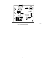
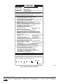
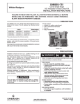
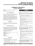
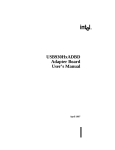
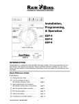
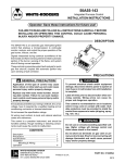
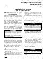
Fixed Speed Furnace Control
Replacement Kit
Cancels: New
IIK 349M-50-1
9-98
Installation Instructions
Part No. CESO110057-02
NOTE: Read the entire instruction manual before starting the
installation.
SAFETY CONSIDERATIONS
Installing and servicing heating equipment can be hazardous due to
gas and electrical components. Only trained personnel should
install or service heating equipment.
Untrained personnel can perform basic maintenance functions
such as cleaning coils, or cleaning and replacing filters. All other
operations should be performed by trained service personnel.
When working on heating equipment, observe precautions in the
literature, on tags, and on labels attached to the unit.
Understand the signal words DANGER, WARNING, and CAUTION. These words are used with the safety-alert symbol. DANGER identifies the most serious hazards which will result in severe
personal injury or death. WARNING signifies a hazard which
could result in personal injury or death. CAUTION is used to
identify unsafe practices which would result in minor personal
injury or product and property damage. NOTE is used to highlight
suggestions which will result in enhanced installation, reliability,
or operation.
The ability to properly perform service on this equipment
requires certain expertise, mechanical skills, tools, and equipment. If you do not possess these, do not attempt to perform
any service on this equipment other than those procedures
recommended in the User’s Manual. A failure to follow this
warning could result in possible damage to this equipment,
serious personal injury, or death.
INTRODUCTION
Circuit board Part No. CESO110057-02 is a direct replacement for
circuit boards Part No. CESO110057, CESO110057-01,
CESO110057, CESO110048, CESO110020, and HH84AA016.
This revised circuit board has incorporated LED diagnostics as an
aid in troubleshooting. It is recommended that a sight glass (not
included) be installed in a convenient location on the furnace, see
Optional Section. If a sight glass is not installed, the self-test
feature of the board can still be used for routine troubleshooting.
The fault code label provided must be installed on the furnace.
Major changes to the operation of this control include:
1. A 90 sec blower on delay if power is restored during a call for
heat.
6. The inducer will run continuously during the self-test cycle.
7. Nominal flame sensing current is between 4.0 to 5.0 microamps (uA) DC.
On twinned furnace applications, the CESO110057-02 board will
work with any of the above listed circuit boards and a
CESO110005 twinning control module.
NOTE: On twinned applications, the short jumper wire between
pins ST-2 and 225 MUST be removed from remaining circuit
board. Failure to do so will result in incorrect ignitor warm up
times and nuisance furnace lockouts.
ELECTROSTATIC DISCHARGE (ESD) PRECAUTIONS
CAUTION: Electrostatic discharge can affect electronic components. Take precautions during furnace installation and
servicing to protect the furnace electronic control. Precautions
will prevent electrostatic discharges from personnel and hand
tools which are held during the procedure. These precautions
will help to avoid exposing the control to electrostatic
discharge by discharging static electricity build-up to ground.
1. Disconnect all power to the furnace. DO NOT TOUCH THE
CONTROL OR ANY WIRE CONNECTED TO THE CONTROL PRIOR TO DISCHARGING YOUR BODY’S ELECTROSTATIC CHARGE TO GROUND.
2. Ground yourself by touching your hand and tools to clean,
unpainted, metal surface of furnace. close to control.
3. After touching chassis, you may proceed to service the
furnace. You will recharge your body with static electricity by
moving about or shuffle your feet. Reground yourself.
4. If you touch ungrounded objects (recharge your body with
static electricity), reground yourself. Use this procedure for
installed and uninstalled (ungrounded) furnaces.
5. Ground yourself again before handling a new control to
protect control from damage. If control is to be installed in
furnace, follow items 1 through 5 again before installing
control. Put all used AND new controls into containers before
touching ungrounded objects.
6. An ESD service kit (available from commercial sources) may
also be used to prevent ESD damage.
Step 1—Removal of Existing Control
2. The ignitor warm-up time is fixed at 17 sec.
3. The furnace will recycle if pressure switch opens and re-closes
during a call for heat.
4. If limit switch opens 4 times during a call for heat, circuit
board will lockout the furnace for 3 hr before resetting.
5. Blower off delay jumper has been replaced with DIP switches.
Label all wires prior to disconnection when servicing controls. Wiring errors can cause improper and dangerous
operation.
1. Turn thermostat to OFF or set temperature to the lowest
setting.
Manufacturer reserves the right to discontinue, or change at any time, specifications or designs without notice and without incurring obligations.
Book 1 4
PC 101
Catalog No. 535-715
Printed in U.S.A.
Form 58DHC-6SI
Pg 1
9-98
Replaces: New
Tab 6a 8a
2. Turn off electrical supply to furnace.
current. Nominal flame current is between 4.0 and 6.0 microamps
DC. If flame current is below 4.0 microamps DC, remove and
clean flame sensor with fine steel wool, or replace flame sensor.
The furnace control will lock-out when flame current falls to 0.5
microamps DC.
3. Turn off gas supply to furnace.
Failure to turn off the gas and electric supply may result in
explosion, fire, death or personal injury.
Step 3—System Operation
4. Remove furnace blower and control access doors.
1. Perform any other safety checks as deemed necessary (flame
safety, limit switch, vent system etc.).
5. Remove control box cover.
2. Run unit through 1 complete call for heat cycle.
6. Disconnect thermostat and humidifier (if equipped) wires.
OBSERVATION PORT/SIGHT GLASS INSTALLATION
(OPTIONAL)
NOTE: If a sight glass is not installed, current fault code will be
erased when blower door is removed.
7. Disconnect line voltage, blower, EAC, (if equipped) and
transformer wires.
8. Remove wiring harness edge connector and gasket from
circuit board.
Replacement furnace control Part No. CESO110057-02 has LED
fault code capability. To utilize this feature, it is necessary to field
install a sight glass or observation port. The location of this device
will vary depending on the model of the furnace.
9. Remove retaining screws and old circuit board.
10. Inspect control and control box for evidence of water staining.
11. Correct any sources of water leakage (humidifier, evaporator
coil, vent system) into the control area.
Step 1—Upflow Condensing Furnaces
With the blower door(s) removed, locate the LED on the control
board. Check the sides of the casing. You may be able to utilize the
unused condensate drain opening or electrical knock-out as an
observation port on some models. A 1/2-in. electrical box knockout plug must be installed when this option is used.
Step 2—Installing the New Control
1. Ground yourself! Handle circuit board by edges.
2. For 90 percent efficient furnaces, clip JW9 jumper wire. JW9
jumper is located near right-hand corner of circuit board below
HUM-1 terminal. (See Fig. 1.) This will provide 15 sec
inducer off delay.
Step 2—All Furnaces
3. Insert edge of board between tabs of control box.
1. Measure height of LED off the floor for upflow furnaces or off
the blower shelf on downflow/horizontal furnaces.
4. Install circuit board retaining screws.
2. Then measure distance from front inside edge of casing.
5. Connect all line-voltage, low-voltage, and accessory wires.
6. Connect wiring harness edge connector to circuit board.
3. Orient blower door to correct position and mark this location
on front of blower door.
7. Set blower off delay. Blower off delay DIP switch SW1 is
located near right-hand corner of board. (See Fig. 1.)
4. Using a step-drill or chassis punch, drill 1 1/2-in. hole in
blower door.
8. Re-install control box cover.
5. Install a sight glass Part No. 323017-201 or 323018-201 in
blower door.
9. Do not connect thermostat wires to control board until
Start-up and System Check-out is complete.
6. A 1/2-in. hole may be drilled and an electrical box plug may
be used and are available from hardware stores or electrical
suppliers.
SYSTEM CHECK-OUT
Step 1—Component Self Test
NOTE: Do NOT install an observation port or sight glass through
warning labels on furnace. If a warning label interferes with the
observation port, use an alternate location such as side of casing.
1. To initiate component test sequence, ensure thermostat is
turned OFF or thermostat wires are disconnected. Turn power
on and engage blower door switch. With a short piece of wire,
briefly short TEST/TWIN terminal to Com/24v terminal.
Component test sequence is as follows:
Or, a 1/4-in. hole may be drilled in blower door and then plugged
with a 5/16- X 1/2-in. long screw providing it does not interfere
with instructions or control board.
a. Status LED will flash code then turn ON inducer motor.
b. Inducer motor will run for entire component test.
7. A loose fitting sight glass should be sealed with clear silicone
to prevent leakage and sight glass from falling out.
c. Hot surface ignitor and blower motor-heat speed will run
for 10 sec.
8. Install Fault Code label (see Fig. 2) in a convenient location on
blower door adjacent to sight glass.
d. Blower motor-cool speed will be turned on for 10 sec.
2. Repair or replace or service any component that fails during
the self-test. The gas valve is not energized during self-test.
Do not install a sight glass or observation port between the
blower compartment and the furnace vestibule. Do not cover
any port with tape. Do NOT run the unit unattended with the
blower door off. Carbon Monoxide may be drawn into living
space. A failure to follow this warning could result in possible
damage to this equipment, serious personal injury, or death.
3. Turn power off.
4. Disengage blower door switch.
5. Connect thermostat wires.
6. Install blower and access doors.
7. Turn power back on.
8. Turn on gas.
Step 2—Flame Sensor Operation
Connect a DC microammeter in series with flame sensor. Initiate
a call for heat. After burners ignite and stabilize, measure flame
2
C7
R15
R17
(TP1)
JW18
R39
R40
R13
HUM-1
C6
J21
R26
R30
90 135 180 225
R19
JUMPER 9
UNCUT: 5 SEC.,
CUT: 15 SEC.
JW9
R21
INDUCER
OFF DELAY
J16
JW17
1
2
SW1
TEST/TWIN
BLOWER-OFF DELAY
SWITCH SETTING
A98511
Fig. 1—Part of Control Board
3
SERVICE
LED CODE
CONTINUOUS OFF CONTINUOUS ON RAPID FLASHING -
STATUS
Check for 115VAC at L1 and L2, and 24VAC at
SEC-1 and SEC-2.
Control has 24V power.
Line voltage (115V) polarity reversed. If twinned, refer to
twinning kit instructions.
EACH OF THE FOLLOWING STATUS CODES IS A TWO DIGIT NUMBER WITH THE
FIRST DIGIT DETERMINED BY THE NUMBER OF SHORT FLASHES AND THE
SECOND DIGIT BY THE NUMBER OF LONG FLASHES.
11 NO PREVIOUS CODE - Stored status codes are erased when power (115V or 24V)
to control is interrupted or 48 hours after each fault is cleared.
12 BLOWER ON AFTER POWER UP (115V or 24V) - Blower runs for 90 seconds,
if unit is powered up during a call for heat (R-W closed).
13 LIMIT OR FLAME ROLL-OUT SWITCH LOCKOUT - Auto reset after three hours.
For flame roll-out switch or fuse link, refer to #33.
14 IGNITION LOCKOUT - Control will auto-reset after three hours. Refer to #34.
21 GAS HEATING LOCKOUT - Control will NOT auto reset.
Check for: - Stuck gas valve relay on control or miswire to gas valve circuit.
22 ABNORMAL FLAME-PROVING SIGNAL - Flame is proved while gas valve is
de-energized. Inducer will run until fault is cleared. Check for:
- Stuck-open gas valve or leaky gas valve.
23 PRESSURE SWITCH DID NOT OPEN Check for:
- Obstructed pressure tubing.
- Defective pressure switch
(stuck closed).
24 SECONDARY VOLTAGE FUSE IS OPEN
Check for: - Short circuit in secondary voltage (24V) wiring.
31 PRESSURE, DRAFT SAFEGUARD, AUXILIARY-LIMIT (when used), OR
BLOCKED VENT SHUTOFF (when used) SWITCH DID NOT CLOSE OR
REOPENED - If open longer than five minutes, inducer shuts off for 15 minutes
before retry. Check for:
- Proper vent sizing and condensate pitch
- Inadequate Combustion air supply.
or sag.
- Low inducer voltage.
- Vent restriction or high winds.
- Disconnected or obstructed
- Defective inducer motor or start capacitor.
pressure tubing.
- Defective pressure switch or connections. If it opens after trial for ignition period,
blower will come on for 90 second recycle delay.
33 LIMIT OR FLAME ROLL-OUT SWITCH IS OPEN - If open longer than three
minutes,code changes to #13. Check for:
- Defective blower motor or start capacitor.
- Dirty filter or restricted duct system.
- Loose blower wheel.
- Defective switch or connections.
- Inadequate Combustion air supply Flame Roll-out Switch or fuse link.
- Open Flame Roll-out switch,or fuse link. Manual reset or replace.
34 IGNITION PROVING FAILURE - Control will try three more times before a lockout
#14 occurs. If flame signal lost after trial for ignition period, blower will
come on for 90 second recycle delay. Check for:
- Oxide buildup on flame sensor (clean with fine sandpaper).
- Proper flame sense microamps (.5 microamps D.C. minimum).
- Gas valve turned off. - Manual shut-off valve. - Low inlet gas pressure.
- Green wire MUST be connected to furnace sheet metal.
- Inadequate flame carryover or rough ignition.
COMPONENT TEST
To initiate the component test sequence,shut OFF the room thermostat or disconnect the
"R" thermostat lead. Briefly short the TEST terminal to the ’Com 24V’ terminal. Status
LED will flash code and then turn ON the inducer motor. The inducer motor will run for
the entire component test. The hot surface ignitor, blower motor-heat speed, and blower
motor-cool speed will be turned ON for 10-15 seconds each.
LED
W
Y
R
Com
24V
TEST / TWIN
G
997-420001-1
A98512
Fig. 2—Service Label for LED Code
Copyright 1998 Carrier Corporation
349m501
Manufacturer reserves the right to discontinue, or change at any time, specifications or designs without notice and without incurring obligations.
Book 1 4
PC 101
Catalog No. 535-715
Printed in U.S.A.
Form 58DHC-6SI
Pg 4
9-98
Replaces: New
Tab 6a 8a