1
x 50 + I x 130 or 2 x 130 Watt Audio Amplifier
Limiting and HUSH@ Noise Reduction
Amphwdia4x50ou2x50+1x130ou2x1300Watts
ion de distorsion THD et Rbduction de bruit
ifi~dowdeaudio4x50o2x50+1 x130o2x130
10s con limitacibn de distorsiiin THD y Reduccih de
..
Made
,iti
the U.S.A.
Bosch Group
TABLE OF CONTENTS
(ENGLISH)
Introduction, Owner’s record, and key features
Velacity amplifier features (Distortion Limiting, HUSH noise gating and reduction,
Voltage Controlled Amplifier’s)
Installation and safety precautions
Amplifier controls and operation
Amplifier connections and interface
Speaker configurations
Recommended system configurations (4)
Final installation (Mounting and ventilation, use of internal crossovers, fusing,
power and speaker wiring)
Trouble-shooting guide
Limited warranty (United States)
Accessories
Other notes
Technical specifications
PAGE
3
4-6
7
8
9
10
11-14
15-17
18
19
54
54
55
20
Introduction, Archive du proprietaire, caracteristiques-cl6
Velocity comprendre le fonctionnement de I’amplificateur (caracteristiques de limite de distorsion
21-23
de signal, reduction de bruit HUSH et filtre de Porte d’expansion descendante, VCA)
24
Montage et mesures de securite
25
Commandes de I’amplificateur et fonctionnement
26
Raccordements de I’amplificateur et interface
27
Configurations de speaker
28-31
Configurations des systemes (4)
Montage final (Montage et ventilation adequats, interface du signal d’entree, utilisation des
32-34
croisements internes et des commances d’intensite, mise a la masse, fusibles)
35
Guide de depannage
36
Garantie limitee @tats - Unis)
54
Accessoires
.
54
Autres notes
55
Specifications
INDICE DE MATERIAS
(ESPAfiOL)
37
Introduction, archive del del propietario, caracteristicas del amplificador Velocity
Characteristics del amplificador \(e/oc;ry (Limitaci6n de distorsion, circuit0 de conduccidn selectiva
38-40
y reduction de ruido HUSH, amplificadores de voltaje controlado, configuraciones)
41
Precauciones de instalacidn y seguridad
42
Controles y operation del amplificador
43
Conexiones del amplificador e interfase
4
4
Configuraciones del speaker
45-48
Configuraciones recomendadas del sistema (4)
lnstallacidn final (Montaje y ventilaci6n adecuados, uso de truces internos, fusibles apropiados,
49-51
cableado de alimentacidn y de 10s altavoces)
52
Gula para solucionar problemas
53
Garantia limitada (EE. UU.)
Accesorios
Otras Notas
55
Especificaciones
2
INTRODUCTION
Congratulations on your purchase of the world’s finest brand of car audio amplifiers. We have
invested tremendous effort in the design process of the new VELOC/TT”series amplifiers in order
to achieve superior musical performance. Leading edge technologies such as Distortion Limiting
and HUSHTM noise reduction and gating, previously found only in the professional audio sound
reproduction and enhancement market, have been implemented into your VELOCITYT” amplifier
which has been designed and assembled in the United States of America. For maximum
performance and reliability we highly recommend that your new VELOC/w”’ series amplifier be
installed by an authorized Blaupunkt dealer. We also recommend Blaupunkt cd or cassette units,
speaker systems, and accessories to expand the listening experience which might be limited by
lesser quality components.
Finally, we remind you to practice safe listening habits using common sense. Continuous exposure
to listening levels over 100 decibels may cause permanent hearing loss. Many high power, multispeaker systems today are capable of Sound Pressure Levels exceeding 130 dB.
OWNER’S RECORD
..
del and warranty numbers are located on the bottom of the unit. Please record these
s in the space provided below. Refer to these numbers whenever you call upon your
Blaupunkt dealer.
MODEL:
WARRANTY NUMBER:
PURCHASE DATE:
DEALER/INSTALLER:
KEY FEATURES
DISTORTION LIMITING (THD,) reduces the annoying acoustical pops and cracks present during
high signal levels. It is acoustically transparent until high signal levels thus providing protection
for tweeters since high level distortion products are not allowed to enter the speakers.
HUSHTM NOISE GATING AND REDUCTION offers tremendous noise reduction for background
hiss that may be picked up in the installation or from recorded music played back via AM, FM,
or even compact disc.
MULTI-MODE SPEAKER CAPABILITY allows the consumer to cost effectively create a
satellite/subwoofer system with remarkably good performance from a single amplifier.
REMOTE GAIN AND HUSH CONTROLS are available using the optional remote control, RM-1.
This remote can change gains of the entire system (multiple amplifiers) or only a subwoofer
amplifier if so configured.
TONE AND BASS BOOST CONTROLS provide frequency response tailoring for the end listener
that cannot be achieved from the radio controls.
1 OHM STABILITY allows for paralleling of multiple speakers for increased sound pressure level.
CONTINUOUSLY VARIABLE HIGH-PASS/LOW-PASS CROSSOVERS allow you to better
istribute amp power thus lowering system distortions and increasing system sound loudness.
IDE RANGE INPUT GAIN CONTROLS (0.3 - 6.0 V rms) allow for a variety of radio interface
voltages, even directly from the high level outputs of many factory radios.
3
UNDERSTANDING YOUR AMPLIFIER’S FEATURES
WHAT IS AN AMPLIFIER?...
An amplifier, by definition, is a device that receives a small audio signal on its input and reproduces
it with larger voltages (or current) on its output. Ideally there should be no internal modifications of
the signal other than voltage or current level. If there are any changes in the signal character it is
4
considered a “distortion” of the input signal.
A perfect amplifier will be able to reproduce any output voltage regardless of input signal level, but
this is impossible due to upper limits created by the voltages found in a car, typically 12 - 15 volts
DC. The amplifier’s output stage cannot swing voltages that exceed the upper limit commonly
referred to as the voltage “rails”, as in locomotive train tracks. If the input signal is driven to high
levels, the outputs try to follow this path but crash into the “rails” thus turning musical sine waves
into very unmusical square waves. Here is where your new Blaupunkt VELOCIWTMamplifier is
uniquely impressive.
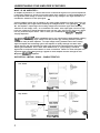
The Blaupunkt VELOCITYTM series of amplifiers have a very unique feature called Distortion Limiting
(THD,) which tolerates high input voltage levels but prevents ugly sounding distortion products
common to nearly all other amplifiers. An input voltage sensing network looks at the incoming
signal and adjusts the feed-through gain of the amplifier so quickly that high level bass notes
cannot drive the amp into distortion yet lower signal level mid and high frequencies pass throu
without gain modification. This is done within milliseconds, so “gain pumping” acoustical
byproducts of inexpensive audio limiters are never encountered. Below is a visual description of a
high level audio signal passing through a typical car audio amplifier and then through the new
Blaupunkt VELOCITYTM amplifiers.
DISTORTION LIMITING SIGNAL CHARACTERISTICS
Low Volume
Typical Amplifier
BlaupunM with TH[x
High Volume
;FII+
Typical Amplifier
jz++
6/8upunkt
with THIX
HUSHm NOISE REDUCTION AND DOWNWARD EXPANSION GATING
High quality compact discs provide very wide range volume levels with low background hiss levels.
Unfortunately, the car is a very noisy electrical environment so vehicle noises (pops and alternator
whine) often creep into the audio signal somewhere in the installation. Although mid and high level
music tends to mask background noises, vehicle noises become quite audible, and annoying, during
quiet music passages. This problem has been known for some time in the professional audio field
so a device known as a “Noise Gate” has been used to mute the signal path during quiet passages.
The problem with this system is the “choppy” sound as the Gate opens and closes with music
which is known as “pumping”.
The HUSHTM noise reduction circuits avoid this “pumping” by the use of a downward expander
which effectively expands the dynamic range of the signal thus pushing down the background
noise in relation to the desired signal. Also, the HUSHTM circuits offer a continuously variable set
point that smoothly moves up and down so none of the dramatic “pumping” of the desired signal is
experienced as with a noise gate. An added benefit is the ability of the HUSHTM circuit to reject
noise on recorded music such as cd’s, cassettes, and even on the AM/FM car radio.
INPUT/OUTPUT ELECTRICAL TRANSFER FUNCTION
-80 -60 -40 -20 OdB
OUTPUT SIGNAL
OUTPUT SIGNAL
OUTPUT SIGNAL
SIGNAL TO NOISE CHARACTERISTICS
VERY LOW
MUSIC SIGNAL
LOW LEVEL
MUSIC SIGNAL
MID LEML
MUSIC SIGNAL
5
VCA’s (Voltage Controlled Amplifiers) & ELECTRICAL PIN-OUTS
Used in Professional Audio for some years, but totally new to the car audio world, is a remote
control gain devices called a “VCA”. This is a small integrated circuit that can control the feedthrough gain of a circuit from a remote location. It operates much like an external “hand” that
controls the signal flow through a circuit, much like a simple water flow valve.
OdB
VCA CONTROL VOLTAGE ------+
-20
-40
-60
SIGNAL INWTS
m
K
THDL
LIMITING
-80
-100
-100 -80 -60. -40 -20 ode
CONTROL
+ VOLTAGE
/J
I
VCA OPERATION I-
VCA TRANSFER FUNCTION
Many people want to have a remote control for a high power amplifier in order to control the
loudness of a subwoofer amplifier independently of the radio. Remote mounting of an input gain
control would be a major problem with most car audio amplifiers because of the likely noise
intrusion into the signal path.
With a VCA circuit on the input of an amplifier, the gain can be controlled remotely but is done
with moderate level DC voltages (O-1 5 volts) that are insensitive to noise (noise is an AC voltage).
Using the optional Blaupunkt remote control (RM-1) you simply plug the remote into the amp to
control the overall gain. For people wanting to interface with highly custom installations, you can
use an RJ-11 telephone jack and variable resistor to achieve similar results using the circuit below,
This is & recommended for very experienced Blaupunkt installation centers for it may void the
warranty of the amplifier otherwise.
l
-
REMOTE GAIN CONTROL
ELECTRICAL PINOUT
6
. ..--
INSTALLATION AND SAFETY PRECAUTIONS
!! WARNING !!
8 ALWAYS DISCONNECT THE (+I LEAD FROM THE BATTERY OF THE
VEHICLE BEFORE DOING ANY INSTALLATION WORK!
8 DO NOT INSTALL THIS UNIT IN THE ENGINE COMPARTMENT!
8 DO NOT RUN WIRES UNDERNEATH OR OUTSIDE THE VEHICLE!
!! SAFETY PRECAUTIONS !!
._
nalyze the mounting location carefully to avoid damaging gas tanks, electrical wires, and/or
draulic lines.
2.
Every effort should be made to provide adequate ventilation, protection from engine heat, direct
sunlight, rain, and dirt.
3.
This unit is designed for use only with 12 volt DC negative ground vehiclt systems.
4.
This unit is NOT designed for use with common ground speakers. All speakers MUST be
connected to both positive and negative terminals.
5.
Fuse the + 12V lead of the amplifier before making any electrical connections in the vehicle.
Fuse the line as close to the battery as possible. Always use the fuse supplied with this amp
and never increase the fuse size (for example, 10A) in case it does blow.
6.
Be sure all power grounds are clean. Scrape off paint if necessary to guarantee this.
7.
Make wiring connections from one component to the next, making sure that you plug radio or
equalizer outputs to amplifier inputs and not outputs to outputs.
8.
Do not run power cables and audio (RCA) cables together. You can minimize noise radiation by
running the power cables on one side of the car and the signal cables on the opposite side.
9.
Avoid sharp edges and door jambs when running the wires. Electrical tape or grommets should
be used protect the wires when they are routed through holes.
10. Make sure all wire connections are secure and protected so there is no danger of nicks or
pinched electrical lines.
11. FOR SAFE DRIVING keep the listening levels low enough not to mask outside noises.
12. Avoid playing your car audio system for long periods of time at high listening levels when the
engine is not running. This will prevent unnecessary battery drain.
7
AMPLIFIER CONTROLS AND OPERATION
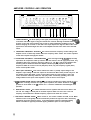
1. TONE CONTROLS - The tonal quality of the signal passed through the amplifier can be modi
in the bass and treble regions using the internal tone controls. Although somewhat redunda
to those on the radio, these controls help correct for small equalization problems in the car
without changing the controls on the radio. This helps improve the Signal to Noise ratio of the
system since the boosted highs are done in the amplifier and not at the other end of the RCA
cables.
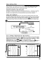
2. CROSSOVER FREQUENCY SETTINGS - The internal crossover frequency control setting of the
amplifier can be continuously variable within the frequency limits shown. This control operates
in both the low-pass and high-pass modes.
3. CROSSOVER FREQUENCY CONFIGURATIONS - In the full-range mode (5-50,000 Hz) the amp
reproduces all frequencies heard by humans. With the control in the HP (high-pass) mode, only
information above the crossover frequency setting (e.g., 120 Hz) is sent to the speakers thus
assuming that an additional subwoofer amplifier exists to properly reproduce the bass
frequencies. With the control in the LP (low-pass) mode, only low frequency signals (bass)
comes out the speaker leads.
4. INPUT GAIN CONTROLS - This control matches the radio or preamp output voltage to the
amplifier’s input voltage so that full output can be achieved. Most radios provide only 0.5-l .OV
rms output at their RCA leads, so this control offers nearly any input voltage. Turning the
control clockwise effectively makes the amp play louder. Technically speaking, this is the
voltage needed on the input of the amplifier in order to drive it to full output.
5. 4/3/2 CHANNEL MODE SELECT SWITCH - For 4 channel operation this switch should be in the
141 position. To bridge channels for higher power operation, this switch should be in the 121
position for 2x130 watts or the 131 position for a 3 channel combination stereo/bridged mono
operation.
6. BASS BOOST ON/OFF - This switch should be used for systems that need a more bass in the
low end. It is simply a narrow peak in the bass response which can add a nice “full” low
frequency sound without the broader frequency impact of the bass tone control.
7. DISTORTION LIMITING ON/OFF - When turned on, this control enables the THD, circuit. When
switched on the circuit greatly reduces all distortion products at high levels but is electrically
transparent at all other listening levels. In the OFF (bypass) mode, the distortion limiting
feature is disabled so typically unwanted clipping harmonics pass on to the speakers.
,
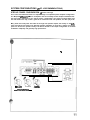
AMPLIFIER CONNECTIONS AND INTERFACE
I
.
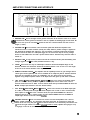
1. GROUND LINE - This is the high current ground connection to the chassis of the car. It should
be fastened to a clean ground connection in the car, capable of handling high current loads. Do
not run a wire up to the car battery- ground for this line. It should remain less than 3 feet in
length (1 meter).
2. TRIGGER LINE - This connection is the connection point that allows the amplifier to be
switched on from a remote location (usually the radio). When a positive voltage is applied to
this terminal the amplifier will switch on. This connection is normally made from the power
antenna lead of the radio or a dedicated trigger line. It will turn the amp on for any voltage
above 10 volts. Make sure the radio’s power antenna lead is activated only when the radio is
turned on.
3.
BATTERY LINE - A high current, fused line should be connected at this point with battery level
voltages (typical 12.5 - 14.5 V DC) available 24 hours a day.
4.
FUSES - These fuses are only for catastrophic situations should the amplifier begin to self
destruct. Another fuse should be located at the battery before a run of wire is run the length
of the car to the remote location of the amplifier.
5.
REMOTE CONTROL INPUTS - This amplifier has the capability to have its gain changed from a
remote gain control (optional) and uses a standard RJ-11 telephone jack for interface. Should
more than one amplifier be used in an installation, you can “daisy chain” these controls
together using simple telephone cables so all amps move their gains up and down in tandem.
6.
LEFT FRONT 81 RIGHT FRONT / MONO [Al INPUTS - These lines connect to the RCA output
jacks of a radio, or directly from the high level audio outputs from a radio. In the 4 and 3
channel modes these are LF & RF. In the 2 channel mode the input marked MONO A drives the
MONO A output (left channel in the two channel mode).
7. LEFT REAR & RIGHT REAR / MONO IBI INPUTS - These lines connect to the RCA output jack
of a radio, or directly from the high level audio outputs from a radio. In the 4 channel mode,
these inputs are LR & RR. In the 3 channel mode, the input marked MONO B is the third
(bridged) channel. In the 2 channel mode, the input marked MONO B drives the MONO B
output (right channel in the two channel model.
SPEAKER OUTPUTS - These connections are used to connect loudspeakers with 1 ohm or
higher speaker impedance. It is imperative that these lines NOT be connected or touch the
I
fi
L. chassis of the car in any way (the f-1 lead of the left channel is not electrically connected to the
(-1 lead of the right channel so common arounds cannot be used). Speaker wire gauges of up
to 8 gauge in size can be accommodated by these terminals.
9
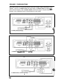
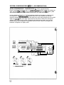
SPEAKER CONFIGURATIONS
Many audio systems can be generated from the three basic speaker output configurations of this
amplifier. They are: 4 CHANNEL MODE (full range audio); 3 CHANNEL MODE (2 channel highpass/l channel low-pass); and 2 CHANNEL MODE (2 channel full-range or low-pass subwoofer).
Possible in-car configurations will be covered elsewhere in this manual.
3 CHANNEL (2 Chnnel HiihPeeUl Channel Low-Pau)
L
2 CHANNEL MODE (2 Channel Full Range)
.
10
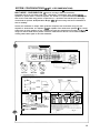
SYSTEM CONFIGURATIONS (#l OF 4 RECOMMENDATIONS)
STEP-UP POWER CONFIGURATION (4
channel full-range)
One ‘of the most difficult decisions in amplifier usage is an optimized power amplifier configuration.
The Blaupunkt VEf 0C/7YT” series of amplifiers has the versatility to offer multiple installations but
the most easily understood is the “step-up power” configuration. You simply run RCA cables from
the radio back to the amp, install a good set of coaxial front and rear speakers, and then play loud!
Many head units today offer 4x15 watts at the high level speaker outputs, but usually on the leftfront and right-front channels only. Although speaker installation is good, this is simply not enough
power for most music dynamics today. The obvious benefit in this simple configuration is minimum
installation complexity and generally high performance.
.
g W/RF
q
Cl+U?/RR
- CROSSOVER SWTCHES -
CHANNEL
SWITCH
SYSTEM CONFIGURATIONS (#2 OF 4 RECOMMENDATIONS)
SATELLITE/SUBWOOFER CONFIGURATION (3 channel high-pass/low-pass)
Another common configuration is that of a “satellite/subwoofer” speaker system. By breaking the
audio spectrum (20 - 20,000 Hz) into two parts (e.g., above and below 100 Hz) amplifier power
and associated loudspeakers can be better proportioned to the needs of most music.
For truly dynamic performance, a dedicated subwoofer amplifier and speaker are needed for the
low frequencies. A “satellite/subwoofer” system allows for a lower powered mid and high
frequency amplifier (e.g., 4x15 watts inside the radio) but a much higher powered unit for the bass
region (e.g., 1x100 watts) since larger signal levels are found here in most music. Placing the
amplifier into 3 channel mode creates a complete high-pass/low-pass system. The front two
channels default into the high-pass configuration and the rear two channels are bridged into a
subwoofer configuration for higher power.
m ClUF/l?F
q C-B)
-CROBBOVERBWlTCHEB-
CHANNEL
SWITCH
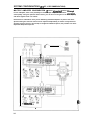
SYSTEM CONFIGURATIONS (973 OF 4 RECOMMENDATIONS)
.
MULTI-MODE CONFIGURATION (4 channel full-range w/derived subwoofer)
Somewhat new to the car audio world is the “multi-mode” configuration which permits three
speakers to operate from a 2 channel amplifier. The benefit is a “quasi-satellite/subwoofer” system
that can be constructed using passive components (i.e., capacitors and inductors) but we highly
recommend the optional “Blaupunkt Bass Bridge” (BE11 to ensure easy and correct installation as
well as reliability.
Overall, this installation is simple, offers good bass response, and can be done using only one
amplifier as shown below. The amplifier must be capable of this multi-mode operation - you cannot
simply hook up three speakers to any 2 channels and get this performance! The amp is run fullrange in 4 channel mode with a passive crossover network across the two rear channels thus
creating amono-bass signal to drive the subwoofer.
r
2ohm
cicoawu
WOOFER
R+L
6
MHZ
loo HZ
1SOM
2oatiz
LWU
40mH
32ml-i
Zlmti
16mH
4olml
C(clpclaw)
1003
600
530
400
pF
PF
VF
PF
Lwn
6OmH
64mH
4.2 mH
32mH
Cr-v@w
500
400
270
2~
&JF
VF
uF
IJF
CAUTION:
- Be ewe that the combined impedance of your
speaker system as seen from the amplifier terminals is
at least 2 ohms. An impedarea of less than 2 ohms will
cause the amp to shut down.
13
SYSTEM CONFIGURATIONS (#4 OF 4 RECOMMENDATIONS)
MULTIPLE AMPLIFIER CONFIGURATION (2 channel subwoofer/ channel full-ranae)
For the audiophile, there is the possibility to install multiple amplifiers and achieve unparalkled
sound quality. Using the optional remote control, you can also run the gains of all three amps up
and down together from one remote.
Performance is tremendous since you are dedicating individual amplifiers to parts of the music
spectrum thus gain and tone controls can be adjusted independently to achieve a truly balanced
sounding system. Since the second amp is bridged for additional power, this provides even more
impressive deep bass response.
---14
c
.
FINAL INSTALLATION
Proper installation of your amplifier should also address several areas; adequate mounting and
ventilation, proper signal input interface, correct use of internal crossover networks, “clean”
power/ground wiring, proper fusing, and power/speaker wiring.
ADEQUATE MOUNTING AND VENTILATION
Inevitably this amplifier will be mounted in locations with limited space. If possible, try mounting
the amplifier on a vertical surface with the fins up/down for best vertical air movement. The
mounting screws supplied with this unit should be used for the most secure installation.
SIGNAL INPUT INTERFACE
This amplifier can accept input signals up to 6 volts rms over the RCA input jacks. Due to high
input signal capabilities, people may want to interface the high level output of a radio (2-4 Vrms) to
the input of the amplifier. This can be easily done by connecting the ” +” lines of the two speaker
outputs to the center conductors of the RCA jacks. One common sjgnal ground reference wire is
connected from the radio chassis to the shields of the RCA lines connecting to the amplifier input.
RCALEIW
D-1
‘LOW LML AUDIO
c
“HIGH LML AUDIO”
RR-
USE OF INTERNAL CROSSOVERS AND TONE CONTROLS
Internal active crossover networks allow for this amplifier to be configured in three possible modes;
OFF (FULL-RANGE) disables the crossover so &l frequencies pass through the amplifier, HP (HIGHPASS) passes only frequencies above the crossover control setting, and LP (LOW-PASS or
SUBWOOFER) passes only frequencies below
I
n the crossover
t
control
h
esetting.
L
P
(SUBWOOFER) mode the slope of the crossover is 12 dB/octave at low frequencies (@ 20 Hz), but
at the higher end of the control (@220 Hz), the slope approaches 24 dB/octave. This prevents
male voices from sounding bad if the control setting is set up around the 220 Hz value.
r
LP (LOW PASS) CROSSOVER
I
I
HP (HIGH PASS) CROSSOVER
OdB
IB
per
-3
TAVE
/
-12
54
-36
“CLEAN” POWER AND GROUND
Unfortunately, the number of electronic devices in the car has grown such that care must be taken
to properly install the power and ground connections of the amplifier in order to prevent
overloading the charging system of the vehicle or interjecting noise. Currents are high enough that
a dedicated power line should be run directly to the battery of the car, but not to the vehicle’s
alternator output. This line should not be run to a fuse on the factory fuse panel of the car but
directly to the battery with its own fuse immediately at the battery. The ground terminal of the
amplifier should be terminated at the other end to a clean metal on the chassis of the car.
Noise can enter over the battery power line, power ground, or most commonly over the RCA signal
input lines. The amplifier has very high rejection to noise coming in over the heavy power line so
most noise intrusion is via the ground connections and/or RCA input leads. Although this amplifier
has Differential Inputs at the RCA leads, noise can still enter the shields of the RCA cables if these
are run near noise producing objects such as engine or braking system computers. More common
is alternator whine generated from ground point voltage differences due to component connections
throughout the vehicle (voltage ground loops). The best installation design to prevent this
condition is done using a “star” grounding scheme (shown below) to ensure a common ground
point for all stereo components.
Radio
Equalizer (Optional)
3tar
Ground
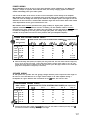
PROPER FUSING
This unit will operate over a range of lo-18 volts DC. A high current fuse should be installed inline with the amplifier(s) immediately at the battery to prevent vehicle damage should the battery
line be inadvertently shorted to the vehicle chassis. The chart below shows recommended master
fuse sizes for an average audio system with the noted audio power levels.
FUSE SIZE FOR TOTAL SYSTEM AUDIO POWER (max output level)
Standard fuse sizes commonly used in the automotive world today. Fuse size should exceed the maxlmum current
draw expected to accommodate music transients. (Current draw above reflects a minimum system voltage of 12.6
dc at the amplifier with current values for maximum current draw with music signals.)
.
16
POWER WIRING
Most automobiles built in the last 10 years have adequate current capability for your Blaupunkt
amplifier. Except for systems above 500-700 watts, the factory charging system and battery
should comfortably power your audio system.
Care should be taken in the choice of wire to ensure adequate current delivery to the amplifier.
Wire diameter size (gauge) is an important factor for high power audio systems. The main battery
cable size needs to change with audio power demands. The amplifier power and length of wire run
determine the wire size that is needed. Wire diameters larger than those shown below offer limited
sonic improvements for the given increased wire cost.
Wire diameter must increase (decreased wire gauge number) for higher power systems. For
amplifier installations long distances from the car battery, the wire diameter needs to increase
(decreased wire gauge number). The power wire sizes below are sizes that allow for a maximum of
0.5 Volts DC voltage drop over the given wire length (this power line voltage drop is virtually
inaudible at the speakers and will not cause problems with your Blaupunkt amplifier).
POWER AND GROUND WIRING CHART*
/
WIRE LENGTH
WIRE GAUGE FOR TOTAL SYSTEM AUDIO POWER (max output level)
(feet / meters)
50 w
(4 A rms)
100 w
(8 A rms)
200 w
(16 A rms)
500 w
(40 A rms)
1000 w
(80 A rms)
5 ft. / 1.5 m
16
12
10
8
4
10 ft. / 3.0 m
16
12
10
8
4
15 ft. / 4.5 m
14
12
10
20 ft. / 6.0 m
14
12
IO
6
6
2
25 ft. 17.5 m
12
IO
8
4
0 or 00
30 ft. / 9.0 m
12
10
8
4
0 or 00
b
+
2
American Wire Gauge Sizes (A.W.G.) for amplifier power and ground leads. This chart reflects maximum voltage drop
of 0.5 V dc over the given wire length. (Current draw above reflects a minimum system voltage of 12.6 V dc at the
amplifier with current values for maximum current draw with music signals. Wire gauge numbers are also inflated by 2
gauge sizes to compensate for voltage drops in connectors.)
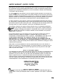
SPEAKER WIRING
As with power wire, speaker wire size (gauge) changes with the power required and the length of
the wire run. The chart below is for a single channel output of an audio amplifier driving a
loudspeaker at a given distance with a maximum of 0.5 dB power loss over the wire.
LOUDSPEAKER WIRING CHART*
WIRE LENGTH
(feet / meters)
+
WIRE GAUGE FOR TOTAL SYSTEM AUDIO POWER (max output level)
low
20 w
50 w
100 w
200 w
5 ft. / 1.5 m
20
18
16
16
16
10 ft. / 3.0 m
20
18
16
16
16
15 ft. / 4.5 m
18
16
16
16
14
20 ft. / 6.0 m
18
16
16
16
14
25 ft. / 7.5 m
4,O ft. / 9.0 m
18
16
1
14
12
18
16
16
14
12
6
American Wire Gauge Sizes (A.W.G.) for paired speaker wires. This chart reflects a maximum power drop of 0.5 dB
(well below the threshold of audibility) over the given wire length.
TROUBLE-SHOOTING GUIDE
GYMPTOM
. No power (blue
PROBABLE CAUSE & SOLUTIONS
remote turn-on
l
light is off)
.
.
.
Check connections to the amplifier’s + 12 volt, Ground, and remote lines
Verify the appropriate voltages are at their terminals (1 l-1 5 VDC).
Check the main power connection at the battery.
Check fuse in power line. If fuse is blown, replace it. If it continues to
blow, see your Blaupunkt dealer.
Disconnect all speakers and try to power up unit. If it now turns on, a
speaker short is probable.
Power but no sound (blue
remote turn-on light is on)
.
l
Check all RCA input cables and speaker output cables.
Test the speaker with a VOM to verify > 1 ohm loads per channel.
I.
No sound from one channel
or entire side
0
.
.
Check radio balance and fader control positions.
Check loudspeaker connections.
Check cd changer connections (if applicable).
1.
Very low sound level
.
.
Check radio balance and fader control positions.
Check amplifier’s input gain control setting - adjust for higher output
levels if possible.
Head unit may have extremely low output voltage. A step-up voltage
!.
.
1.
Power amplifier turns on and off 0
.
repeatedly (Motor boating)
.
i.
Amp sounds fine but gets
very warm to the touch
.
0
.
Input gain control is set too high; lower input level accordingly.
Verify that speaker load impedances are > 1 ohms per channel.
Verify that the mounting location allows for free air movement around the
amp. The largest area should be above the unit since heat rises.
‘.
Amplifier turns off during
loud passages or is distorted
l
Input stage being severely overdriven. Lower input gain.
Verify that speaker load impedances are > 1 ohms per channel.
Verify that one of the speaker outputs is not shorted to the chassis of the
car.
l
.
I.
Amplifier turn-on/off pops or
noises
l
.
I.
Crackling noise on AM and FM
radio, but not on tape or cd.
Varies with accelerator but is
present at all times.
(This is “radiated” noise)
l
.
.
.
Make sure connections at battery are tight.
Check battery voltage at amp using VOM; it should be 1 l-1 5 VDC.
Check all radio and amplifier ground connections.
Disconnect the RCA input lines to the amp and turn amplifier unit on and
off via the Trigger line. If pop goes away, the amp is turning on faster
than the time required for the radio outputs to settle down. A turn on
delay line may be needed.
If the noise persists, disconnect the Trigger line from the head unit and
try connecting directly to the battery. If the noise goes away, use a relay
to switch the trigger line from the clean power source.
Make certain the problem is “radiated” noise by placing a portable FM
radio near the car engine. If noise is picked up, then it is an automotive
problem and not your system.
Make sure the spark plugs and wires are <2 years old; otherwise
replace.
Verify that the engine block is grounded to the car chassis, not paint.
Verify the hood is ground to chassis. If not, purchase a flexible metal
strap, scrape off paint at the connections, and screw into place.
IO. Whining noise (alternator whine) l
occurs while engine is running
l
and varies in pitch with engine
speed (this noise VARIES with . . 0
radio’s volume setting}.
Check power connections to be sure they are clean.
Reroute power to the radio so that it runs directly from battery bypassing
battery terminal in fuse box.
Check ground connections to be sure surfaces have been scraped clean
for good connections.
I 1.
Check battery ground connection at chassis to make sure it’s clean and
tight. Verify that all connections are scraped clean of paint, rust, or
grease.
Check radio and amp connections; you may have to relocate amplifier
ground to same point as radio ground.
Bypass all equipment between radio and amp (e.g., equalizers, etc.) and
connect directly to amp. If problem goes away, reinsert each componerr
until noise reappears. Logic shows this part is the problem.
Check for “high level ground loops”; turn off and disconnect unit
grounds, one at a time, except for the power amp. Turn system back on
and check for noise after each ground is removed.
Check for RCA shield “signal level ground loops” by disconnecting th
shield of the RCA cable at one end. If noise disappears modify cable
accordingly.
Whining noise (alternator whine) l
occurs while engine is running
and varies in pitch with engine
speed {this noise DOES NOT
.
vary with radio’s volume
setting}.
.
0
0
18
LIMITED WARRANTY (UNITED STATES)
Robert Bosch Corporation warrants new Blaupunkt audio products’and accessories it distributes in
the United States through authorized Blaupunkt dealers, or which are imported as original vehicle
equipment by the automobile manufacturer, to be free from defects in material and workmanship,
in accordance with the following:
For twelve (12) months after delivery to you, the original consumer purchaser, we will repair any
amplifier and replace any accessory which under normal conditions of use and service proves to be
defective in materials or workmanship at no charge to you. However, this warranty does not cover
expenses incurred in the removal or reinstallation of any amp or accessory whether or not proven
defective and does not cover products not purchased from an authorized Blaupunkt dealer.
To obtain performance of this warranty, contact the nearest Blaupunkt authorized repair facility or
our nearest office. A dated purchase receipt or other proof that the product is within the warranty
period will be required in order to honor your claim. Carefully pack the unit and ship prepaid to the
servicing location. For further information, contact your local Blaupunkt retail dealer.
This warranty is limited to the original consumer purchaser and is not transferable. Specifically
luded from this warranty are failures caused by misuse, neglect, abuse, improper operation or
allation, dropping or damaging the faceplate, or unauthorized service or parts. Also excluded
this warranty is the correction of improper installation and the elimination of any external
electromagnetic interference.
To the extent allowed by law, this warranty sets out your exclusive remedies with respect to
products covered by it, whether for negligence or otherwise. We will not be liable for
consequential or incidental damages, losses, or expenses. THIS WARRANT? IS IN LIEU OF ALL
OTHER EXPRESS WARRANTIES. ANY WARRANTY IMPLIED BY LAW, WHETHER FOR
MERCHANTABILITY OR FITNESS FOR A PARTICULAR PURPOSE OR OTHERWISE, SHALL BE
EFFECTIVE ONLY FOR THE PERIOD THAT THIS EXPRESS WARRANTY IS EFFECTIVE. No attempt
to alter, modify, or amend this warranty shall be effective unless authorized in writing by an officer
of Robert Bosch Corporation.
Some states do not allow limitations on how long implied warranties last, or the exclusion or
limitation of incidental or consequential damages, so the above limitations or exclusions may not
apply to you. This warranty gives you specific legal rights and you may also have other rights
which vary from state to state.
NOTICE TO CALIFORNIA OWNERS
If your Blaupunkt car audio product needs warranty repair service and there is no authorized service
center reasonably close to you, you can return the defective unit to the dealer from whom you
purchased it. Or you can return it to any dealer who sells Blaupunkt products. The dealer may
repair or replace the unit, or, if returned to the dealer from whom purchased, he may partially
refund your money, you may take your Blaupunkt unit to any repair shop and they can repair your
unit at our expense unless the repair cost exceeds the depreciated value of the unit, but you must
contact Blaupunkt to receive authorization to do this before your unit is repaired.
ROBERT BOSCH CORPORATION
BLAUPUNKT DIVISION, UA/CSV
2800 SOUTH 25TH AVENUE
BROADVIEW, ILLINOIS 60153
TEL: 708-865-5200
P
c
NOTICE TO NON-U.S.A. OWNERS:
‘I
.a~ducts sold outside the United States are subject to the limitations of that Blaupunkt region or
country. Please contact your Blaupunkt dealer for further explanation of the repair or replacement
process.
19
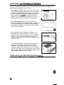
ACCESSORIES / ACCESSOIRES / ACCESORIOS
There are four accessories available for your Velocity amplifier which increase its flexibility and
guarantees high performance for years to come.
1
RM-1, REMOTE CONTROL: This control offers the consumer
the capability of remotely controlling the gain of a subwoofer
amplifier, or multiple amplifiers, from the front seat of the car.
The control also has the capability to change the threshold
(turn-on point) for the HUSHTM noise reduction inside the
amplifiers. This control uses simple telephone wire and RJ-11
jacks to interconnect and is insensitive to vehicle noises.
I
2. BB-1, BASS BRIDGE: Mixed mode stereo/mono can be
created using simple passive components (coils and capacitors)
but can be confusing for the average installer. We highly
recommend that the BB-1 be used to avoid possible confusion
and ensure proper operation.
3 . EC-l, END CAP: If only one amplifier is installed in a car,
these end caps can be placed at either end of this amp to
protect the control settings and wires. If two or more amps
are used, an EC-l can be mounted between two amps to
“bridge” the gap between the two amps thus trimming out the
appearance nicely.
4 . CB-1, CAPACITOR BANK: The main benefit of any kind of
capacitance at the power line into the amp is for power
stabilization. This problem may show up as the vehicle’s
headlights “dancing” with the music. It may also be heard as
“singing” noises from inside the amplifier due to heavy current
loads. The CB-1 simply connects to the power terminals of the
amp in parallel with those from the vehicle.
OTHER NOTES / AUTRES NOTES / OTRAS NOTAS
54
RM-1 REMOTE GAIN CONTROL
VEIL OCITpM V450 TECHNICAL SPECIFICATIONS
EEATURE/PARAMETER
Channels
Size (h x w x d)
Weight
Crimping style speaker terminals
Maximum wire size
Blue power-on LED
Controls on one end/connectors on the other
Noise reducing differential input circuits
Inputs isolated from ground
Subsonic filter
Separate front/rear gains
Spade type automobile fuses
Speaker short, short to + 12V 81 ground protection
High, low, reverse voltage protection
Power output transistors
hing power supply transistors
pedance stability:
VAiUE
41312
11 .O” (55 x 248 x 280mm)
10.0 Ibs (4.5 kg)
YES
8 ga.
YES
YES
YES
YES
YES (10 Hz)
N/A
YES
YES
YES
High-current bipolar
MOSFET’s
1 fi stable (4 ch mode only)
4 R stable in bridge mode (2 n not
212 X 9.75 X
recommended due to high current draw
from the amplifier)
PERFORMANCE DATA
Power output @ 0.1% THD:
4 channel into 4/2/l D
Bridged channel(s) into 4 f2
Total Harmonic Distortion:
@ full rated output
@ 1 watt/l kHz
Signal/Noise ratio:
@ full rated power
@ lwettll kHz
Damping factor
Frequency response (in full range mode)
High-pass crossover frequency limits
Low-pass crossover frequency limits
Tone control turn-over frequencies
Tone control boost/cut limits
Input impedance
Input signal voltage control
Currant draw/efficiency @ 14.4 V dc:
@ full rated power (2 ch into 4 $2)
@ 33% power (high listening levels)
@ idle
Battery voltage to maintain rated power
Usable battery voltage
Trigger line voltage
Trigger line current draw
Turn on delay time
Thermal power rollback temperature (non-muting)
Input common mode rejection
er supply ripple rejection
9te control gain range
p”
AH
noise reduction due to downward expansion
*_
Note: Due to ongoing product improvement.
VALUE
5ow /75w j5ow
13ow
0.05%
0.07%
102
85
>200
5-50.000 Hz
20-220 Hz
20-220 Hz
130 Hz (bass) & 6 kHz (treble)
+lO/-10dB
40 k ohms
0.3 - 6.0 V rms
26.6 A I 52 %
15.0 A132 %
1.5 A / Not Applicable
12.6 V dc
10 - 18 V dc
7.5-18Vdc
C 15mA
1.5 s
170 “F (80°C)
> 65 dB
> 70 dB above 1 kHz
0 to -3OdB
> 20 dB
specifications and design are subject to change without advanced notice to the
consumer and/or retailer.
55
Bosch Group
Robert Bosch Corporation
Sales Group - Blaupunkt Division
2800 South 25th Avenue, Broadview, Illinois 60153
Division Blaupunkt de Robert Bosch Inc.
6811 Century Avenue
Mississauga, Ontario
Canada L5N 1Rl
Robert Bosch, SA., DE, C. V.
Dr. Lucia 270
Cols. Doctores, Mexico 06720
Copyright 1994 by the Robert Bosch Corporation
No portion of this work may be reproduced in any form without the
written consent of the Robert Bosch Corporation
The VELOCI~” and HUSHTM names are trademarked by Rocktron Corporation of
Rochester Hills, Michigan, U.S.A.
Printed in the U.S.A (41941