1
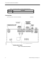
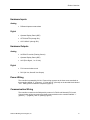
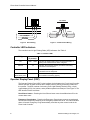
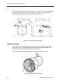
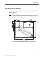
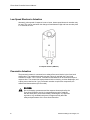
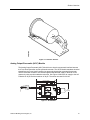
Two-State Constant Volume
Fume Hood Controller
Owner’s Manual
125-5033
Rev. AA, September 2007
Rev. AA, September 2007
NOTICE
The information contained within this document is subject to change without notice and should not be
construed as a commitment by Siemens Building Technologies, Inc. Siemens Building Technologies, Inc.
assumes no responsibility for any errors that may appear in this document.
All software described in this document is furnished under a license and may be used or copied only in
accordance with the terms of such license.
WARNING
This equipment generates, uses, and can radiate radio frequency energy and if not installed and used in
accordance with the instructions manual, may cause interference to radio communications. It has been
tested and found to comply with the limits for a Class A digital device, pursuant to Part 15 of the FCC rules.
These limits are designed to provide reasonable protection against such interference when operated in a
commercial environment. Operation of this equipment in a residential area is likely to cause interference in
which case users at their own expense will be required to take whatever measures may be required to
correct the interference.
SERVICE STATEMENT
Control devices are combined to make a system. Each control device is mechanical in nature and all
mechanical components must be regularly serviced to optimize their operation. All Siemens Building
Technologies branch offices and authorized distributors offer Technical Support Programs that will ensure
your continuous, trouble-free system performance.
For further information, contact your nearest Siemens Building Technologies, Inc. representative.
Copyright 2007 by Siemens Building Technologies, Inc.
TO THE READER
Your feedback is important to us. If you have comments about this manual, please submit them to
[email protected]
CREDITS
APOGEE is a registered trademark of Siemens Building Technologies, Inc.
Insight for Minicomputers is a registered trademark of Siemens Building Technologies, Inc.
Insight for Personal Computers is a registered trademark of Siemens Building Technologies, Inc.
™
UniTrak is a trademark of Siemens Building Technologies, Inc.
Teflon is a registered trademark of DuPont.
Country of Origin: US
Table of Contents
How To Use This Manual ............................................................................................. VII
Manual Organization ................................................................................................. VII
Manual Conventions.................................................................................................. VII
Manual Symbols ........................................................................................................ VIII
Datamate Software.................................................................................................... VIII
Getting Help .............................................................................................................. VIII
Where To Send Comments ....................................................................................... VIII
Product Overview ......................................................................................................... 1
Introduction ................................................................................................................... 1
Related Equipment .................................................................................................... 1
Electronic Actuation ................................................................................................ 1
Pneumatic Actuation ............................................................................................... 1
Ordering Notes ....................................................................................................... 2
Hardware Inputs ........................................................................................................ 3
Analog ..................................................................................................................... 3
Digital ...................................................................................................................... 3
Hardware Outputs ..................................................................................................... 3
Analog ..................................................................................................................... 3
Digital ...................................................................................................................... 3
Power Wiring ............................................................................................................. 3
Communication Wiring .............................................................................................. 3
Controller LED Indicators .......................................................................................... 4
Operator Display Panel (ODP) .................................................................................. 4
Laboratory Exhaust Air Terminal............................................................................... 5
Venturi Air Valves ...................................................................................................... 6
Electronic Actuator Assembly
................................................................................................................................... Err
or! Bookmark not defined.
Pneumatic Actuator ................................................................................................... 8
Analog Output-Pneumatic (AO-P) Module ................................................................ 9
Differential Pressure Transmitter .............................................................................. 10
Airflow Sensor ........................................................................................................... 10
Cables ....................................................................................................................... 10
Siemens Building Techologies, Inc.
V
Applications .................................................................................................................. 11
Fume Hood Controller: 2-Position Constant Volume ............................................... 11
Basic Operation ............................................................................................................ 12
High and Low Exhaust Flow Control ......................................................................... 12
Control Loops ......................................................................................................... 12
Calibration ................................................................................................................. 12
DO3 Output Functionality .......................................................................................... 13
Warning and Alarm Features .................................................................................... 13
Warning Operation.................................................................................................. 13
Alarm Operation...................................................................................................... 13
Alarm Strategies ..................................................................................................... 14
Emergency Purge Feature ........................................................................................ 14
Emergency Purge Operation .................................................................................. 14
Emergency Purge Strategies .................................................................................. 15
Fail-safe Operation .................................................................................................... 16
Fume Hood Controller ............................................................................................ 16
ODP ........................................................................................................................ 16
Differential Pressure Transmitter ............................................................................ 16
Electronic Actuator Assembly ................................................................................. 16
Pneumatic Actuator ................................................................................................ 16
AO-P Module .......................................................................................................... 16
Point Database.............................................................................................................. 17
Troubleshooting ........................................................................................................... 20
Basic Service Information ......................................................................................... 20
Preventive Maintenance ............................................................................................ 20
Safety Features ......................................................................................................... 21
Controller LEDs ......................................................................................................... 21
Glossary ........................................................................................................................ 22
Index .............................................................................................................................. 26
VI
Siemens Building Technologies, Inc.
How To Use This Manual
This section covers manual organization, conventions, and symbols used in the
manual, and other information that will help you understand and use a Laboratory
Room Controller — Electronic Output.
Manual Organization
This manual contains the following sections:
•
Chapter 1 Product Overview describes the hardware components and the
accessories that are used with the controller.
•
Chapter 2 Applications describes the control applications available in the
controller.
•
Chapter 3 Point Database defines the point database descriptors and
includes address and applications.
•
The Glossary describes terms and acronyms.
•
The Index helps you find information.
Manual Conventions
The following table lists conventions used in this manual.
Convention
Actions that you should
perform are specified in
boldface font.
Example
Type F for Field panels.
Click OK to save changes and close the dialog box.
Error and system
messages are displayed
in Courier New font.
The message Report Definition successfully renamed
appears in the status bar.
New terms appearing for
the first time are
italicized.
The Open Processor continuously executes a user-defined set of
instructions called the control program.
Siemens Building Techologies, Inc.
VII
Manual Symbols
The following table lists symbols that are used to draw your attention to important
information.
Notation
Symbol
Meaning
CAUTION:
Indicates that equipment damage or loss of data may occur
if the user does not follow a procedure as specified.
WARNING:
Indicates that personal injury or loss of life may occur to the
user if a procedure is not performed as specified.
Datamate Software
Datamate is a customer software tool for all controller communications. There are
two versions: Datamate Base, and Datamate Advanced. Datamate Base works on an
IBM-compatible Personal Computer (PC), or a Handheld PC or Pocket PC™ running
Windows CE. Datamate Advanced works only on an IBM-compatible Personal
Computer. With Datamate, you can backup, restore, and edit any APOGEE database
(but only Datamate Advanced allows you to edit points offline). Backing up and
restoring a database can be accomplished while connected to any APOGEE field
panel, or to the Building Level Network (BLN) or Floor Level Network (FLN) device in
question. A modem and telephone lines can also be used. Databases can be saved
to a hard or floppy disk and kept for permanent storage or used as backup.
For more information on Datamate software, refer to the appropriate user guide
based on which version of Datamate you are using (Base or Advanced), or contact
your local Siemens Building Technologies, Inc. representative.
Getting Help
If at any time you find that you need help with a Laboratory Room Controller issue
not covered in this manual, contact your local Siemens Building Technologies, Inc.
representative.
Where To Send Comments
Your feedback is important to us. If you have comments about this manual, please submit them
to [email protected]
VIII
Siemens Building Technologies, Inc.
1
Product Overview
Introduction
The Fume Hood Controller is an equipment controller designed to provide Direct Digital
Control (DDC) for 2 position fume hoods. The controller consists of a controller board and a
controller enclosure. The controller board (Figure 1) is the central computing/controlling
component of the system.
Related Equipment
•
Operator Display Panel (ODP)
•
Laboratory Exhaust Air Terminal
•
Venturi Air Valve
•
Differential Pressure Transmitter (See NOTE)
•
Airflow Sensor (See NOTE)
•
Cables
Electronic Actuation
•
Electronic Actuator Assembly (See NOTE)
Pneumatic Actuation
•
Analog Output-Pneumatic (AO-P) Module (See NOTE)
•
Pneumatic Actuator (See NOTE)
NOTE:
These components may be included in the Laboratory Exhaust Terminal or
Venturi Air Valve.
Siemens Building Technologies, Inc.
1
Fume Hood Controller Owner's Manual
Table 1. Fume Hood Controller – Electronic Output Applications.
Application
940
Description
2 Position Fume Hood Controller
Ordering Notes
Fume Hood Controller – Electronic Output (940)
546-00750
Figure 1. Fume Hood Controller Board .
2
Siemens Building Technologies, Inc.
Product Overview
Hardware Inputs
Analog
•
Differential pressure transmitter
•
Operator Display Panel (ODP)
•
ATTN.UNATTN (through DI1)
•
OCC.UNOCC (through DI1)
Digital
Hardware Outputs
Analog
•
AO-E/AO-P module (Floating Control)
•
Operator Display Panel (ODP)
•
AO2 (Flow Signal, 1 to 10 Vdc)
•
FLN communications trunk
•
DO3 (24 Vac, Alarm/Hi.Low Output)
Digital
Power Wiring
The controller is powered by 24 Vac. Power wiring connects to the three screw terminals on
the controller labeled “C” (Common), “H” (Hot) and “E” (Ground) on the terminal block labeled
“TB1”. Earth ground connection is required (Figure 2).
Communication Wiring
The controller connects to the field panel by means of a Field Level Network (FLN) trunk.
Communication wiring connects to the three screw terminals on the controller labeled “+”
(positive), “-“ (negative), and “S” (Shield) (Figure 3).
Siemens Building Technologies, Inc.
3
Fume Hood Controller Owner's Manual
FLN TRUNK
+ - S
TEC0470R1
LAB00140R1
(SHIELD)
24V COMMON
24V HOT
GROUND
Figure 2. Power Wiring.
(SHIELD)
(-)
(+)
(-)
(+)
Figure 3. Communication Wiring.
Controller LED Indicators
The controller has six Light Emitting Diode (LED) indicators. See Table 2.
Table 2. Controller LEDs.
LED Type
Label
(if present)*
Indication
DO
LED 1 - LED 3
Transmit
TX
Indicates, when flashing, that the controller is transmitting
information to the field panel.
Receive
RX
Indicates, when flashing, that the controller is receiving
information from the field panel.
BST
”Basic Sanity Test”
BST
Indicates, when flashing ON and OFF once per second, that
the controller is functioning properly.
Indicates the ON/OFF status of the DO associated with it. A
glowing LED indicates that the DO is energized.
Operator Display Panel (ODP)
The Operator Display Panel (ODP) is the interface device between the Fume Hood Controller
and the operator. Its main functions are to display normal, warning, and alarm conditions to
the operator. The ODP consists of a housing, three Light Emitting Diodes (LEDs), a liquid
crystal display (LCD), four buttons, and a portable operator's terminal port. See Figure 4. The
ODP buttons function as follows:
Horn Silence button – Pressing the Horn Silence button turns the audible alarm off for the
current alarm event.
Emergency Purge button – Pressing the Emergency Purge button removes contaminated
air from the fume hood by switching to an emergency exhaust flow level. The internal audible
alarm will sound. Emergency Purge automatically overrides any other control mode in the
Fume Hood Controller.
4
Siemens Building Technologies, Inc.
Product Overview
Pressing the Emergency Purge button a second time reverts the Fume Hood Controller to
normal operation for the current conditions.
HI/LO: HI/OFF Select button – Pressing this button changes the controller from a high flow
setpoint to a low flow setpoint and back again or changes the controller from a high flow
setpoint to and OFF state and back again.
Auxiliary Button – The Auxiliary buttons are not used currently.
For more information on the ODP, see the Fume Hood Controller Operator Display Panel
User's Card (125-1976).
Figure 4. Operator Display Panel.
Laboratory Exhaust Air Terminal
The Laboratory Exhaust Air Terminal is a pre-packaged, easy to install, airflow measurement
and control station. See Figure 5. It combines an orifice plate flow sensor, differential
pressure transmitter, an electronic actuator assembly, or No. 3 pneumatic actuator, and
Analog Output-Pneumatic (AO-P) Module, and butterfly damper in a 20 gauge 316 stainless
steel duct section.
This arrangement provides fast acting, stable, and precise VAV fume hood exhaust airflow
control.
Siemens Building Technologies, Inc.
5
Fume Hood Controller Owner's Manual
The terminal is available in diameters ranging from 4 to 18 inches. The terminal is available in
a variety of end configurations to match the ductwork construction. It is also available in
TEFLON® coated 18-gauge steel for highly corrosive environments.
Figure 5. Laboratory Exhaust Air Terminal.
Venturi Air Valves
The Venturi Air Valve is a pre-packaged, easy to install airflow measurement and control
station. See Figure 6. This assembly combines the orifice plate flow sensor, differential
pressure transmitter, Electronic actuator and a Venturi Air Valve.
FUM0400R1
This arrangement provides fast acting, stable, and precise exhaust airflow control.
Figure 6. Single-Body Venturi Air Valve.
6
Siemens Building Technologies, Inc.
Product Overview
High Speed Electronic Actuation
The High speed electronic actuator assembly consists of two parts, the electronic actuator
and the interface board. The actuator is connected to the exhaust flow control device in the
fume hood exhaust duct. The electronic actuator assembly is used because of its small size
and quick response time.
CAUTION:
Due to the design parameters and the response time required by the Fume Hood
Controller, the assembly must be replaced with the same part or a Siemens
Building Technologies, Inc. approved equivalent. Any modifications that are not
approved may affect the safety and performance of the Fume Hood Controller.
AO - E
MODULE
1
1
4.5
1
3.5
FUM0319R3
11.75
14.5
ACTUATOR
Figure 7. Electronic Actuator Assembly in an Exhaust Air Terminal Enclosure.
Siemens Building Technologies, Inc.
7
Fume Hood Controller Owner's Manual
Low Speed Electronic Actuation
Alternately, when speed of response is not an issue, slower speed electronic actuation may
be used. This can be used when the change-of-state between High and Low can take place
in 15 seconds or more.
Low Speed Actuator (GMA13x).
Pneumatic Actuation
The pneumatic actuator is connected to an exhaust flow control device in the fume hood
exhaust duct. The standard pneumatic actuator (Figure 8) used with the Fume Hood
Controller is the No. 3 unit. The No. 3 actuator is used because of its small size and quick
response time. The actuator has a deep drawn aluminum housing, a rubber diaphragm, and
a spring return rated at 8 to 13 psi. Pneumatic actuation requires two components, the
actuator and the transducer (AO-P module).
WARNING:
Due to the design, parameters and the response times required by the
Fume Hood Controller, the No. 3 actuator always must be replaced
with the same part or a Siemens Building Technologies, Inc. approved
equivalent. Any modifications that are not approved may affect the
safety and performance of the Fume Hood Controller.
8
Siemens Building Technologies, Inc.
Product Overview
Figure 8. Pneumatic Actuator.
Analog Output-Pneumatic (AO-P) Module
The Analog Output-Pneumatic (AO-P) Module is an electric-to-pneumatic interface between
the Fume Hood Controller and the pneumatic actuator. The AO-P Module translates electrical
signals from the Fume Hood Controller into pneumatic signals that command the actuator.
The AO-P Module consists of two industrial grade solenoids that supply or bleed air to the
actuator by using a pulse modulation technique. See Figure 9. Minimum air supply to the AOP Module is 18 psi and the maximum is 30 psi. The valves are rated for 24 Vac.
5.00" (127.0mm)
3.70"
(94.0mm)
R
(ACTUATOR)
FUM0240R1
S
(SUPPLY)
18-30 PSI
SUPPLY
COMMON
EXHAUST
SUPPLY
EXHAUST
Figure 9. AO-P Module.
Siemens Building Technologies, Inc.
9
Fume Hood Controller Owner's Manual
NOTE:
While the pneumatic actuator is being commanded, you may hear a hissing or
clicking sound coming from the AO-P module. This is due to the movement of the
air valves and the bleeding of air from the actuator. This is normal operation.
Differential Pressure Transmitter
The differential pressure transmitter is used to send a signal that represents the velocity of air
in the duct to the controller. The differential pressure transmitter receives the velocity
pressure signal from the airflow sensor (orifice plate). The transmitter is a dead-end device
which prevents the exhausted fume hood air from flowing through the transmitter or the
sensor.
NOTE:
In accordance with laboratory ventilation safety standards and regulatory
agencies, the performance of the fume hood should be checked annually, as a
minimum, to ensure continued safe and proper operation. Consult Siemens
Building Technologies for more information about a comprehensive laboratory
ventilation system evaluation and associated test programs.
Airflow Sensor
Airflow sensors are used in conjunction with the differential pressure transmitter. The airflow
sensor senses an average air velocity across the duct section. Using the average air velocity
and the duct area, the controller calculates the airflow.
CAUTION:
Ensure that the sensor and exhaust system materials match the fume hood usage.
Exhausting corrosive fumes may corrode the sensor and exhaust system.
Cables
The Fume Hood Controller connects to the portable operator's terminal with the controller
interface cable (P/N 540-143). This cable has an RJ-11 connector (similar to a phone jack)
on one end, and a larger, 9-pin connector on the other end. The RJ-11 connector plugs into
the bottom of the ODP. For more information, see the Fume Hood Controller Operator
Display Panel User's Card (125-1976). The 9-pin connector plugs in the communication port
of the portable operator's terminal. For more cable information, contact your local Siemens
Building Technologies, Inc. representative.
10
Siemens Building Technologies, Inc.
2
Applications
Fume Hood Controller: 2-Position Constant Volume
Application 940 is designed for use with a constant volume or two-position fume hood in a
manifold fume hood exhaust system. In this application, two position fume hoods have an
individual exhaust damper or venturi air valve connected to a central fan. The application
modulates the exhaust flow control device to maintain a high or low flow setpoint based on
inputs from the ODP (Operators Display Panel), Digital Input, an exhaust airflow sensor, and
the controller setpoints (Figure 10).
Figure 10. Application 940 Control Drawing shown using a damper.
Siemens Building Technologies, Inc.
11
Fume Hood Controller Owner's Manual
Basic Operation
The Fume Hood Controller provides Direct Digital Control (DDC) technology for controlling
fume hood face velocities in a manifolded fume hood exhaust system.
High and Low Exhaust Flow Control
The Fume Hood Controller can operate at two different setpoints, described as HI flow and
LOW flow setpoints. The low setpoint can be set to zero to send the controller into an OFF
mode. The OFF mode shuts off the flow alarms and closes the exhaust flow control device
and allows the controller to go into a standby mode of operation.
The Operators Display Panel (ODP) can display HI/LOW setpoint or output exhaust flow in
CFM. Due to display limits, the actual number displayed is CFM divided by 10.
Control Loops
The PID loop controls the exhaust flow control device based on the values of the exhaust
flow and the flow setpoint. The loop output controls the supply and exhaust through a time
modulation scheme. The control loopout ranges from -100 to 100%.
•
-100% is the maximum supply that closes the exhaust flow control device at full
speed.
•
0% holds the exhaust flow control device at its current position.
•
100% is the maximum exhaust that opens the exhaust flow control device at full
speed.
Electronic
The controller sends a separate signal to each of the two inputs that reside on the AO-E
module. For values of 100% to 0%, the controller sends a decreasing percentage of the full
signal length to the retract input. For values of 0% to -100%, the controller sends an
increasing percentage of the full signal to the extend input.
Pneumatic
The controller sends a separate signal to each of the two solenoids that reside on the AO–P
module. For values of 100% to 0%, the controller sends a decreasing percentage of the full
signal length to the exhaust solenoid. For values of 0% to -100%, the controller sends an
increasing percentage of the full signal length to the supply solenoid.
Calibration
Air Velocity Sensor - Calibration of the controller's air velocity sensor is periodically required
to maintain accurate air velocity readings.
12
Siemens Building Technologies, Inc.
Applications
DO3 Output Functionality
DO3 is designed to operate in two different modes. DO3 can follow the alarm status of the
controller by turning ON during alarm conditions and OFF during normal operation; or DO3
can follow the HI.LOW setpoint status of the controller by turning ON while the controller is in
LOW flow operation and OFF when the controller is in HI flow operation.
Warning and Alarm Features
The Fume Hood Controller indicates fume hood performance problems at two levels,
WARNING and ALARM. The two levels are available so different procedures can be
instituted for each condition. Both levels are indicated locally at the ODP and, if connected to
a field panel, centrally through the APOGEE alarm features.
NOTE:
Central alarms only work if the field panel is specifically set up to receive and
distribute the alarm information. Consult your local Siemens Building
Technologies, Inc. representative for more information on central alarming.
Warning Operation
The Fume Hood Controller announces warning conditions at the ODP. The ODP indicates a
warning condition by illuminating the yellow LED.
If the fume hood is operating and the exhaust volume exceeds the high or low warning limit
for a period greater than the delay timer a warning condition occurs.
For more information on ODP messages, see the Fume Hood Controller Operator Display
Panel User's Card (125-1976).
Alarm Operation
The Fume Hood Controller announces alarm conditions at the ODP. The ODP indicates an
alarm condition in the following three ways:
•
The red LED illuminates.
•
The horn sounds.
•
A text message indicating the specific alarm condition displays.
If the fume hood exhaust flow exceeds the high or low alarm limit for a period greater than
the delay timer an alarm condition occurs. The text message FLO HI or FLO LO displays.
The fume hood operator may silence the horn for the current alarm event by pressing the
Horn Silence button.
Siemens Building Technologies, Inc.
13
Fume Hood Controller Owner's Manual
Alarm Strategies
One approach is to use the ALARMs to indicate a condition that requires immediate attention
and the WARNINGs to indicate a condition that may require attention but is not urgent. In that
case, the alarm limits would be set to indicate that it is unsafe to work at the fume hood. The
warning limits would be set at a level that is safe, but indicates that the system may not be
operating correctly. These values should be selected by the person responsible for laboratory
safety.
The delay timer is adjustable and should be selected with safety in mind. Laboratory safety
procedures will not be effective if there are numerous nuisance alarms. The delay timer
should be set at a sufficiently large interval to prevent nuisance alarms. However, if the delay
timer interval is excessively large, there is a risk of having a laboratory worker standing in
front of an ineffective fume hood for a prolonged period. The delay timer interval should be
selected by the laboratory safety officer with the above considerations in mind.
Emergency Purge Feature
Under certain emergency conditions, such as a spill in the fume hood, it may be necessary to
purge the air from the fume hood. The Emergency Purge sequence enables the fume hood
user to override normal airflow setpoint and temporarily increase the airflow beyond the value
needed to maintain the airflow setpoint.
The Emergency Purge overrides any other control mode in the Fume Hood Controller and
has two modes of operation; maximum purge, and controlled purge.
The maximum purge moves the exhaust airflow control device to full open and holds it there
regardless of airflow. This mode has the advantage of providing immediate expulsion of the
contaminating agent, but may cause airflow problems in the fume hood and reduce the
airflow capacity at other fume hoods.
The controlled purge continues to modulate the exhaust airflow control device and controls
the airflow, but at a higher than normal level.
The Fume Hood Controller can be set up to purge in either mode or to start in maximum
purge and then switch to a controlled purge after an adjustable amount of time.
Emergency Purge Operation
The Emergency Purge sequence is initiated by pressing the Emergency Purge button on the
ODP. When the Emergency Purge button is pressed, the fume hood will go to the maximum
purge for the time selected in the emergency timer. After the emergency timer elapses, the
Fume Hood Controller will begin actively controlling the airflow, but at an increased setpoint.
The Emergency Purge sequence is canceled by pressing the Emergency Purge button a
second time. The ODP indicates an Emergency Purge sequence in three ways:
14
•
The red LED illuminates.
•
The horn sounds.
•
EMERGENCY PURGE and EEE display.
Siemens Building Technologies, Inc.
Applications
The fume hood operator may silence the horn by pressing the Horn Silence button on the
ODP without affecting the Emergency Purge sequence.
In addition to the ODP indicators, the emergency alarm point will toggle to ON and will remain
ON until the sequence is canceled. If the emergency alarm is alarmable in the field panel, the
condition can be indicated at selected terminals if the APOGEE Automation System is set up
for it.
Emergency Purge Strategies
The use of the Emergency Purge button is determined by the work practices established by
the laboratory safety officer. As a general rule, there are two groups that should be aware of
the use of the Emergency Purge button: the laboratory worker and the laboratory safety
officer.
Laboratory worker – In most cases, the laboratory worker uses the Emergency Purge
button to increase the fume hood airflow to minimize a dangerous situation.
The Emergency Purge button should not be used as a way to work around the established
face velocity and minimum flow setpoints in an effort to make the fume hood "even safer".
Laboratory safety officer – For the safety department personnel to use the Emergency
Purge feature effectively, they must select the purge mode that best suits their needs. The
selection may be based on knowledge of industrial hygiene, the chemicals used in the
laboratory, the organization's emergency procedures, and the capacity of the central exhaust
system.
If the maximum purge mode is selected, the emergency timer and the emergency setpoint to
their maximum values.
If the controlled purge mode is selected, the emergency timer is set to 0. Select the value for
the emergency setpoint to indicate how much you want the emergency airflow to increase
over the normal airflow. For example, if your emergency procedures call for closing the fume
hood and starting the emergency purge, decide how much airflow you want compared to the
minimum airflow. If you want twice as much airflow, set the emergency setpoint to 200%; if
you want a 50% increase, set the emergency setpoint to 150%. If you do not intend to have
the laboratory worker close the fume hood, then select the face velocity you want the fume
hood to control to in an emergency. Compare that value to the normal face velocity setpoint
and calculate the emergency setpoint in percent.
NOTE:
During a controlled purge, the increased airflow called for in the controlled purge
may exceed the range of the flow sensor. If so, the system cannot accurately
regulate the airflow and the controller will open the exhaust flow control device
100%.
If a sequence initially employing maximum purge with a switch to controlled purge is desired,
set the emergency setpoint as described for the controlled purge. Select a value for the
emergency timer to tell the system how long to leave the exhaust flow control device open
before switching to controlled purge. Base this on the types of accidents anticipated, the
reason you require a maximum purge, and the reason you want to switch it down to a
controlled purge.
Siemens Building Technologies, Inc.
15
Fume Hood Controller Owner's Manual
In addition to setting up the purge sequence to effectively handle the exhaust needs,
decisions must be made on how to use the information available at the central reporting
station. Consult your local Siemens Building Technologies, Inc. representative for more
information on central reporting and trending of emergency purge information.
Fail-safe Operation
If the Fume Hood Controller or one of its accessories fails, then a failure mode sequence will
be initiated.
Fume Hood Controller
If the Fume Hood Controller power fails, the exhaust flow control device will go to the full
open position. Since there would be no power to the controller, no LEDs or display will be
available on the ODP.
NOTE:
If the power fails to both the exhaust fan and the controller, there will be no
indication except for the absence of the noise that the air makes during
normal operation.
ODP
If the ODP fails, the controller will continue to control the fume hood face velocity. However,
no display or audible alarming will be available.
Differential Pressure Transmitter
If the differential pressure transmitter fails, the controller will control the exhaust flow control
device to the fully open position. The ODP will display FFF and GENERAL FAILURE.
Electronic Actuator Assembly
If the electronic actuator or interface board fails then alarms are displayed on the ODP
indicating unsafe operating conditions.
Pneumatic Actuator
If the actuator fails due to a leak, then the exhaust flow control device will go to the full open
position. Alarms will be displayed on the ODP indicating unsafe operating conditions.
AO-P Module
If the AO-P module fails, alarms will be displayed on the ODP indicating unsafe operating
conditions.
16
Siemens Building Technologies, Inc.
Point Database
3
Point Database
Chapter 3 presents a description of the Fume Hood Controller point database including point
descriptors, point addresses, and a listing of applications in which each point is found.
Address
Descriptor
01
CTLR ADDRESS
Identifies the controller on the FLN trunk. Valid values: 0 through 98.
02
APPLICATION
The identification number of the Application running in the controller.
05
LOW ALM
This point displays an ON or OFF status. When the exhaust flow goes below the
value specified at LOW ALM LMT for the time specified in ALARM TIME, the
point goes into an alarm state (ON); the red LED is illuminated, the alarm
sounds, and the message “FLOW LOW” displays at the ODP.
06
HIGH ALM
This point displays an ON or OFF status. When the exhaust flow goes above the
value specified at HI ALM LMT for the item specified in ALARM TIME, the point
goes into an alarm state (ON); the red LED is illuminated, the alarm sounds, and
the message “FLOW HI“ displays at the ODP.
07
EMER ALM
This point displays an ON or OFF status that indicates if the EMERGENCY
PURGE button on the ODP has been pressed. When the operator presses the
EMERGENCY PURGE button, the point is ON, the red LED is illuminated, the
alarm sounds, and EEE and EMERGENCY MODE display at the ODP. If pressed
again, then the point is OFF. This point can be commanded by a field panel.
08
GEN FAILURE
10
HI ALM LMT
11
HI WARN LMT
The value above FLOW STPT, in percent, at which the yellow LED is illuminated
on the ODP. Valid values: 100 through 255%.
12
LOW WARN LMT
The value below FLOW STPT, in percent, at which the yellow LED is illuminated
on the ODP. Valid values: 0 through 100%.
13
LOW ALM LMT
14
EMER TIMER
Siemens Building Technologies, Inc.
Description
Indicates a hardware failure (e.g., the pressure sensor) with an ON or OFF
status. The red LED is illuminated; the alarm sounds, and FFF and GENERAL
FAILURE display at the ODP.
The value above FLOW STPT, in percent, at which the red LED and audible
alarm are activated on the ODP. This point is the setpoint for HIGH ALM. Valid
values: 100 through 255%.
The value below FLOW STPT, in percent, at which the red LED and audible
alarm are activated on the ODP. This point is the setpoint for LOW ALM. Valid
values: 0 through 100%.
When EMER ALM is set to ON, the time set for EMER TIMER is used as the
length of time the EXH FLOW is commanded to full flow (the exhaust flow control
device is full open). After the time in EMER TIMER times out, the EXH FLOW is
controlled to the value set in EMER STPT. Valid values: 0 through 32, 767
seconds.
17
Fume Hood Controller Owner’s Manual
Address
Descriptor
15
EMER STPT
A value of the preset FLOW STPT, in percent, that the controller uses as the
setpoint when EMER ALM is ON.
16
LOW WARN
This point displays an ON or OFF status. When the exhaust flow goes below the
value specified at LOW WARN LMT for the time specified in ALARM TIME, the
point goes into a warning state (ON); the yellow LED is illuminated at the ODP.
17
HIGH WARN
This point displays an ON or OFF status. When the exhaust flow goes above the
value specified at HI WARN LMT for the time specified in ALARM TIME, the
point goes into a warning state (ON), the yellow LED is illuminated at the ODP.
19
ALM AKNLG
This point displays an ON or OFF status that indicates the Horn Silence button
has been pressed at the ODP to acknowledge an alarm condition. The point will
reset when the alarm condition clears or another alarm is initiated.
27
AO2 DEADBAND
30
AO2 RANGE
Scaling for the Analog Output (AO2) point. To get the correct output, the slope
and intercept of this point must match the point database of the room controller.
34
TRANS RANGE
The maximum range, in inches of water (PA), of the differential pressure
transmitter. Standard values are 0.1 (25.3), 0.25 (62.275), 0.5 (124.55), and 1.0
(253).
35
EXH FLOW
The calculated value, in CFM (LPS), of the exhaust airflow as measured with the
differential pressure transmitter sensor.
36
FLOW COEFF
37
FLOW STPT
38
FLOW LO STPT
The low flow setpoint used in FLOW STPT.
40
CAL DP TRANS
YES or NO point used to calibrate the zero point of the differential pressure
transmitter.
41
DO1 SUP
Digital output 1 is used to control the analog output-pneumatic (AO-P) supply
valve or the AO-E module supply input.
42
DO2 EXH
Digital output 2 is used to control the analog output-pneumatic (AO-P) exhaust
valve or the AO-E module exhaust input.
43
DO3
44
AI1 DP TRANS
45
AI2 0.10V
Analog input 2 is a 0 to 10 Vdc spare input.
46
AO1 0.10V
Spare analog output is a 0 to 10 Vdc output.
47
AO2 FLOW SIG
48
DI1 STPT SW
Digital input for dry contact connection to control the HI/LOW flow setpoint of the
controller.
54
ODP DISPLAY
Controls the function of the ODP display. It will display either CFM divided by
10 or HI FLOW / LO FLOW.
55
DO3 MODE
Controls the function of the DO3. It will follow either the HI/LO setpoint or the
alarm status.
18
Description
When EXH FLOW and FLOW STPT are different by more than the AO2
DEADBAND, the AO2 FLOW SIG changes from setpoint to actual flow.
Gain factor for the flow sensor.
Setpoint, in CFM (LPS), that the airflow is controlled to.
Digital output 3 is a spare output.
Analog input 1, a 4 to 20 mA signal from the differential pressure transmitter.
The point displays the mA value of input from the sensor.
Analog output 2 signal is used to indicate the exhaust flow setpoint. The output
is 1 to 10 Vdc, which corresponds to 0 to A02 RANGE (Point 30).
Siemens Building Technologies, Inc.
Point Database
Address
Descriptor
56
ODP STPT SW
Indicates if the lower left button on the ODP has been pressed. This is a toggle
action digital input; when pressed, the controller changes between HI and LOW
flow setpoints.
57
RIGHT SW
Indicates if the right auxiliary button on the ODP has been pressed. This is a
toggle action digital input; when pressed, the point is ON. If pressed again, the
point is OFF.
63
FLOW P GAIN
The proportional gain value for the fume hood flow control loop.
64
FLOW I GAIN
The integral gain value for the fume hood flow control loop.
66
FLOW D GAIN
The derivative gain value for the fume hood flow control loop.
67
FLOW BIAS
The bias, in percent, of the fume hood flow control loop.
68
CTRL LOOPOUT
Control output of the flow loop. Range: -100% to 100%.
87
FLOW HI STPT
89
HORN
91
BLANK DSPLY
When set to YES, the exhaust flow is not displayed at the ODP.
92
DO2 INVERTER
Setting to NCLOSE allows the controller to operate industry standard floating
control actuators. Setting this point may stop the failsafe operation from
functioning.
93
ENG UNITS
Toggles the display of the ODP from CFM to LPS. Toggling this point does not
change the displayed value at the portable operators terminal.
94
LAMP TEST
Turns on all lights, prompts, and the audible alarm at the ODP.
96
ALARM TIME
Time delay for the red and yellow alarm LEDs used to eliminate sudden changes
and false alarms. The exhaust flow must rise above any of the set limits (for
example, HI ALM LMT) for the amount of time specified at this point before the
ODP indicates an alarm condition.
97
DUCT AREA
Area of the duct, in square feet (SQM), where the air velocity sensor is located.
98
LOOP TIME
The time, in tenths of a second, between control loop calculations.
99
ERROR STATUS
Siemens Building Technologies, Inc.
Description
The hi flow setpoint used in FLOW STPT.
When this point is set to DISABLE, the audible alarm will not sound. All other
alarm functionality is still operational.
The status code that indicates any errors detected during controller power-up.
19
4
Troubleshooting
This chapter describes corrective measures you can take should you encounter a problem
when using the Fume Hood Controller. For issues not covered in this section, contact your
local Siemens Building Technologies, Inc. representative.
You are not required to do any controller troubleshooting. Contact your local Siemens
Building Technologies, Inc. representative if a problem occurs or you have any questions
about the controller.
NOTE:
When troubleshooting, record what the problem is and what actions were
performed immediately before the problem occurred. Being able to describe the
problem in detail is important should you need assistance from your local
Siemens Building Technologies, Inc. representative.
Basic Service Information
Always remove power to the controller when installing or replacing it. Since the controller
does not have a power switch, the recommended method of removing power to a locally
powered controller is to turn OFF the power to the 24 Vac transformer. The recommended
method of removing power to a controller on a power cable (even to service a single
controller) is to turn OFF the power at the transformer.
NOTE:
When removing power to a controller to perform maintenance or service, make
sure that the person in charge of the facility is aware of this and that appropriate
steps are taken to keep the building in control.
Never remove the cover from the controller. There are no serviceable parts inside. If a
problem is found with a controller, contact your local Siemens Building Technologies
representative for replacement. An anti-static wrist strap is recommended when installing or
replacing controllers.
Preventive Maintenance
Most controller components are designed so that, under normal circumstances, they do not
require preventive maintenance. However, devices that are exposed to dusty or dirty
environments may require periodic cleaning to function properly. To ensure optimum system
performance, it is recommended that you discuss the operating requirements of your
application with your Siemens Building Technologies, Inc. representative to determine the
best service support program for your needs.
20
Siemens Building Technologies, Inc.
Troubleshooting
Safety Features
The controller board stores the controller's address, applications, and point values. In the
event of a power failure or a reset, these values are retrieved from the controller’s permanent
memory and are used by the controller unless overridden by a field panel.
Controller LEDs
To determine if the controller is powered up and working, verify that the Basic Sanity Test
(BST) Light Emitting Diode (LED) is flashing ON/OFF once per second. The controller
contains six LEDs located on the circuit board. See the Controller LED lndicators section of
Chapter 1, Product Overview for more information about LEDs.
NOTE:
The TX and RX LEDs indicate communication over the FLN.
Siemens Building Technologies, Inc.
21
Glossary
The glossary contains terms and acronyms that are used in this manual. For definitions of
point database descriptors, see Chapter 3 - Point Database, in this manual. For definitions of
commonly used terms as well as acronyms and abbreviations associated with the APOGEE
Automation System, see the Technical Glossary of Building Controls Terminology and
Acronyms, (125-2185). This book is available from your local Siemens Building
Technologies, Inc. representative.
AI
Analog Input. An AI point is a physical point which accepts a continuous variable signal.
algorithm
Mathematical formula used to calculate an output value using varying inputs.
centralized control
The type of control offered by a controller that is connected, by means of a Floor Level
Network (FLN), with an APOGEE field panel.
control loop
A PID algorithm which is used to control an output based on a setpoint and an input reading
from a sensor.
CV
Constant Volume.
DDC
Direct Digital Control.
DI
Digital Input. A DI point is a physical output point which accepts a two-state signal (that is,
ON/OFF, OPEN/CLOSED, YES/NO, etc.).
DO
Digital Output. A DO point is a physical output point which generates a two-state signal (that
is, ON/OFF, OPEN/CLOSED, YES/NO, etc.).
22
Siemens Building Technologies, Inc.
Glossary
English units
The foot-pound-second system of units for weights and measurements.
equipment controller
A FLN device which provides additional point capacity to a field panel or provides DDC to
individual room or mechanical equipment control. The FHC is a specialized equipment
controller.
field panel
A device containing a microprocessor for centralized control of system components and
equipment controllers. A field panel samples and processes field data, initiates control
actions, communicates with its operators, and generates reports, displays and warnings.
FLN
Field Level Network (formerly known Floor Level Network).
Fume Hood Controller
Multi-application equipment controller designed to provide Direct Digital Control) for various
types of Variable Air Volume (VAV) fume hoods. The controller consists of a controller board
and a controller enclosure.
intercept
Factor which converts analog values (used by the controller) to a form which the user can
understand (engineering units). Slope and intercept constants are determined by the type of
field input/output represented by the physical or virtual point.
loopout
Output of the control loop expressed as a percentage.
LPS
Liters Per Second.
OCC mode
OCCupied mode.
OFF text
Text indicating the de-energized state of a digital point (for example, OFF, CLOSED, NO).
Siemens Building Technologies, Inc.
23
Fume Hood Controller Owner's Manual
ON text
Text indicating the energized state of a digital point (for example, ON, OPEN, YES).
override switch
Button on room temperature sensor which can be pressed by an occupant to change the
status of a room from night mode to day mode for a predetermined time.
PID
Proportional, Integral, Derivative.
Portable Operator’s Terminal
DOS capable laptop computer used along with the Controller Interface Software to monitor
and communicate with Terminal Equipment Controllers.
RTS
Room Temperature Sensor.
sash sensor actuator
Device that rides along the sash sensor strip to vary the resistance reading to the Fume
Hood Controller.
SI units
Systeme International d’Unites. The international metric system.
slave mode
Default application that comes up when power is first applied to a Terminal Equipment
Controller.
slope
Factor which converts analog values (used by the controller) to a form which the user can
understand (engineering units). Slope and intercept constants are determined by the type of
field input/output represented by the physical or virtual point.
stand-alone control
The type of control offered by a controller that is providing independent DDC control to a
space.
24
Siemens Building Technologies, Inc.
Glossary
Terminal Equipment Controller
Siemens Building Technologies, Inc. product family of equipment controllers (one is the Unit
Conditioner Controller – Electronic Output) that house the applications software used to
control terminal units, such as heat pumps, VAV terminal boxes, fan coil units, unit
ventilators, etc.
UNOCC mode
UNOCCupied mode.
Siemens Building Technologies, Inc.
25
Index
A
AI see analog input
airflow sensor ..................................................... 9
analog input ........................................................ 2
analog output ..................................................... 2
AO ........................................... see analog output
AO-P module ...................................................... 8
application 907
control drawing ............................................. 15
applications ........................................................ 2
average face velocity control ........................... 10
B
Basic Sanity Test (BST) ................................... 23
basic service information ................................. 22
BST LED .......................................................... 23
differential pressure transmitter ......................... 9
digital input ......................................................... 2
digital output....................................................... 2
Direct Digital Control .................................... 1, 10
DO .............................................see digital output
E
electronic actuation ............................................ 1
electronic actuator
damper ........................................................... 7
emergency purge ............................................. 12
controlled purge ........................................... 12
lab workers ................................................... 13
maximum purge ........................................... 12
operation ...................................................... 12
safety officer ................................................. 13
strategies ...................................................... 13
emergency purge button .................................... 4
F
C
cables ................................................................. 9
calibration ......................................................... 10
communication
port..........................................................2, 5, 9
communication wiring .................................... 3, 4
connector, RJ-11 ................................................ 9
controller
board .............................................................. 2
hardware.....................................................1–9
LEDs .........................................................4, 12
LEDs/LED indicators .................................... 23
ports ................................................................ 2
troubleshooting ............................................. 22
D
DDC..............................see Direct Digital Control
DI ................................................ see digital input
26
fail-safe operation ............................................ 14
ao-p module ................................................. 14
differential pressure transmitter ................... 14
electronic actuator ........................................ 14
fume hood controller .................................... 14
odp ............................................................... 14
pneumatic damper actuator ......................... 14
Field Level Network (FLN) ................................. 3
field panel......................................................... 10
H
hardware ........................................................ 1–9
LEDs............................................................... 4
power wiring ............................................... 3, 4
hardware inputs ................................................. 3
analog............................................................. 3
digital .............................................................. 3
hardware outputs ............................................... 3
Siemens Building Technologies, Inc.
Index
analog ............................................................. 3
digital .............................................................. 3
horn silence button ............................................. 4
L
laboratory exhaust air terminal........................... 5
Light Emitting Diodes ......................................... 4
Light Emitting Diodes (LEDs) ........................... 23
BST ............................................................... 23
RX and TX .................................................... 23
O
Operator Display Panel ...................................... 4
buttons ............................................................ 4
Light Emitting Diodes (LEDs) ......................... 4
P
pneumatic actuation ........................................... 1
pneumatic actuator
damper ........................................................... 7
pneumatic damper actuator see damper actuator
point database.................................................. 18
power loss ........................................................ 14
power wiring ................................................... 3, 4
product overview
ordering .......................................................... 2
Siemens Building Technologies, Inc.
R
related equipment .............................................. 1
RJ-11 connector ................................................ 9
RX LED ............................................................ 23
S
service information, basic ................................ 22
static discharge ................................................ 22
T
troubleshooting
basic service information.............................. 22
controller....................................................... 22
TX LED ............................................................ 23
V
VA rating ............................................................ 2
W
warning and alarms ......................................... 10
alarm operation ............................................ 11
alarm strategies ............................................ 11
warning operation......................................... 11
warning limits ................................................... 10
wiring
communication wiring................................. 3, 4
power wiring ............................................... 3, 4
27