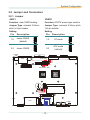
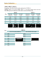
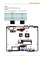
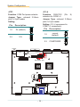
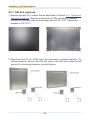
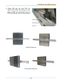
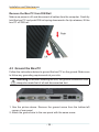
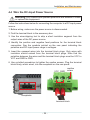
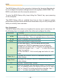
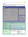
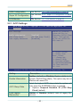
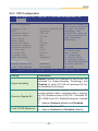
1
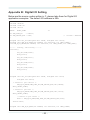
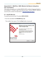
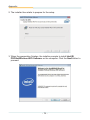
FPC-3131 Series
Robust Box PC with
Intel AtomTM D2550 Platform
®
User’s Manual
Version 1.0
P/N: 4012313100100P
2013.07
Revision History
Version
Date
1.0
2013/07
Description
initial release
Contents
Contents
Preface...............................................................................................iii
Copyright Notice.......................................................................iii
Declaration of Conformity........................................................iii
CE.......................................................................................iii
FCC Class B......................................................................iii
RoHS..................................................................................iv
SVHC / REACH..................................................................iv
Important Safety Instructions...................................................v
Warning......................................................................................vi
Replacing the Lithium Battery.................................................vi
Technical Support.....................................................................vi
Warranty....................................................................................vii
Chapter 1 - Introduction.....................................................................1
1.1 The Product.........................................................................2
1.2 About This Manual..............................................................2
1.3 Specifications......................................................................3
1.4 Inside the Package..............................................................4
1.5 Ordering Information..........................................................4
1.5.1 Optional Accessories..............................................5
1.5.2 Configure-to-Order Service....................................5
Chapter 2 - Getting Started................................................................7
2.1 Dimensions..........................................................................8
2.2 Take a Tour..........................................................................9
2.2.1 Front View................................................................9
2.2.2 Rear View..................................................................9
2.2.3 Side View..................................................................9
2.3. Driver Installation Notice..................................................10
Chapter 3 - System Configuration.................................................. 11
3.1 Board Layout.....................................................................12
3.2 Jumper and Connectors...................................................13
3.2.1 Jumper....................................................................13
3.2.2 Connectors.............................................................17
Chapter 4 - Installation and Maintenance.......................................27
4.1 Install Hardware................................................................28
4.1.1 Remove Top Cover................................................28
-i-
Contents
4.1.2 Install Memory Module..........................................29
4.1.3 Install HDD or SSD.................................................30
4.1.4 Install WiFi or HSUPA Modules (optional)..........31
4.1.5 Install SIM or CFast Card......................................31
4.2 Mount the Computer.........................................................33
4.2.1 Wall-Mount (optional)............................................33
4.2.2 VESA-Mount (optional)..........................................34
4.2.3 DIN Rail (optional)..................................................36
4.3 Ground the Box PC...........................................................38
4.4 Wire the DC-Input Power Source.....................................39
Chapter 5 - BIOS...............................................................................41
5.1 Main....................................................................................43
5.2 Advanced...........................................................................44
5.2.1 ACPI Settings.........................................................45
5.2.2 S5 RTC Wake Settings...........................................46
5.2.3 CPU Configuration.................................................47
5.2.4 IDE Configuration..................................................48
5.2.5 USB Configuration.................................................49
5.2.6 Super IO Configuration.........................................50
5.2.7 H/W Monitor............................................................52
5.3 Chipset...............................................................................53
5.3.1 Host Bridge............................................................54
5.3.2 South Bridge..........................................................56
5.4 Boot....................................................................................58
5.5 Security..............................................................................59
5.6 Save & Exit........................................................................60
Appendix...........................................................................................61
Appendix A: Watchdog Timer (WDT) Setting.......................62
Appendix B: Digital I/O Setting..............................................63
Appendix C: HSUPA or WiFi Hardware Installation.............65
Appendix D: HSUPA or WiFi Software Installation..............69
D.1 HSUPA Module.........................................................69
D.2 WiFi Module..............................................................73
- ii -
Preface
Copyright Notice
All Rights Reserved.
The information in this document is subject to change without prior notice in
order to improve the reliability, design and function. It does not represent a
commitment on the part of the manufacturer.
Under no circumstances will the manufacturer be liable for any direct, indirect,
special, incidental, or consequential damages arising from the use or inability
to use the product or documentation, even if advised of the possibility of such
damages.
This document contains proprietary information protected by copyright. All
rights are reserved. No part of this document may be reproduced by any mechanical, electronic, or other means in any form without prior written permission of the manufacturer.
Declaration of Conformity
CE
The CE symbol on your product indicates that it is in compliance with the directives of the Union European (EU). A Certificate of Compliance is available
by contacting Technical Support.
This product has passed the CE test for environmental specifications when
shielded cables are used for external wiring. We recommend the use of
shielded cables. This kind of cable is available from ARBOR. Please contact
your local supplier for ordering information.
Warning
This is a class A product. In a domestic environment this product may cause
radio interference in which case the user may be required to take adequate
measures.
FCC Class B
This device complies with Part 15 of the FCC Rules. Operation is subject to
the following two conditions:
(1)This device may not cause harmful interference, and
(2)This device must accept any interference received, including interference
that may cause undesired operation.
NOTE:
This equipment has been tested and found to comply with the limits for a
Class B digital device, pursuant to Part 15 of the FCC Rules. These limits
are designed to provide reasonable protection against harmful interference
in a residential installation. This equipment generates, uses and can radiate
radio frequency energy and, if not installed and used in accordance with the
- iii -
Preface
instructions, may cause harmful interference to radio communications. However, there is no guarantee that interference will not occur in a particular installation. If this equipment does cause harmful interference to radio or television
reception, which can be determined by turning the equipment off and on, the
user is encouraged to try to correct the interference by one or more of the following measures:
-- Reorient or relocate the receiving antenna.
-- Increase the separation between the equipment and receiver.
-- Connect the equipment into an outlet on a circuit different from that to
which the receiver is connected.
-- Consult the dealer or an experienced radio/TV technician for help.
RoHS
ARBOR Technology Corp. certifies that all components in its products are in
compliance and conform to the European Union’s Restriction of Use of Hazardous Substances in Electrical and Electronic Equipment (RoHS) Directive
2002/95/EC.
The above mentioned directive was published on 2/13/2003. The main purpose of the directive is to prohibit the use of lead, mercury, cadmium, hexavalent chromium, polybrominated biphenyls (PBB), and polybrominated diphenyl ethers (PBDE) in electrical and electronic products. Member states of the
EU are to enforce by 7/1/2006.
ARBOR Technology Corp. hereby states that the listed products do not contain unintentional additions of lead, mercury, hex chrome, PBB or PBDB that
exceed a maximum concentration value of 0.1% by weight or for cadmium
exceed 0.01% by weight, per homogenous material. Homogenous material
is defined as a substance or mixture of substances with uniform composition
(such as solders, resins, plating, etc.). Lead-free solder is used for all terminations (Sn(96-96.5%), Ag(3.0-3.5%) and Cu(0.5%)).
SVHC / REACH
To minimize the environmental impact and take more responsibility to the
earth we live, Arbor hereby confirms all products comply with the restriction of
SVHC (Substances of Very High Concern) in (EC) 1907/2006 (REACH --Registration, Evaluation, Authorization, and Restriction of Chemicals) regulated
by the European Union.
All substances listed in SVHC < 0.1 % by weight (1000 ppm)
- iv -
Preface
Important Safety Instructions
Read these safety instructions carefully
1. Read all cautions and warnings on the equipment.
2. Place this equipment on a reliable surface when installing. Dropping it or
letting it fall may cause damage
3. Make sure the correct voltage is connected to the equipment.
4. For pluggable equipment, the socket outlet should be near the equipment
and should be easily accessible.
5. Keep this equipment away from humidity.
6. The openings on the enclosure are for air convection and protect the equipment
from overheating. DO NOT COVER THE OPENINGS.
7. Position the power cord so that people cannot step on it. Do not place
anything over the power cord.
8. Never pour any liquid into opening. This may cause fire or electrical
shock.
9. Never open the equipment. For safety reasons, the equipment should be
opened only by qualified service personnel.
10. If one of the following situations arises, get the equipment checked by
service personnel:
a. The power cord or plug is damaged.
b. Liquid has penetrated into the equipment.
c. The equipment has been exposed to moisture.
d. The equipment does not work well, or you cannot get it to work according
to the user’s manual.
e. The equipment has been dropped or damaged.
f. The equipment has obvious signs of breakage.
11. Keep this User’s Manual for later reference.
-v-
Preface
Warning
The Box PC and its components contain very delicately Integrated Circuits
(IC). To protect the Box PC and its components against damage caused by
static electricity, you should always follow the precautions below when handling it:
1. Disconnect your Box PC from the power source when you want to work on
the inside.
2. Use a grounded wrist strap when handling computer components.
3. Place components on a grounded antistatic pad or on the bag that came
with the Box PC, whenever components are separated from the system.
Replacing the Lithium Battery
Incorrect replacement of the lithium battery may lead to a risk of explosion.
The lithium battery must be replaced with an identical battery or a battery type
recommended by the manufacturer.
Do not throw lithium batteries into the trashcan. It must be disposed of in
accordance with local regulations concerning special waste.
Technical Support
If you have any technical difficulties, please consult the user’s manual first
at: ftp://ftp.arbor.com.tw/pub/manual
Please do not hesitate to call or e-mail our customer service when you still cannot find out the answer.
http://www.arbor.com.tw
E-mail:[email protected]
- vi -
Preface
Warranty
This product is warranted to be in good working order for a period of one year
from the date of purchase. Should this product fail to be in good working order
at any time during this period, we will, at our option, replace or repair it at no
additional charge except as set forth in the following terms. This warranty does
not apply to products damaged by misuse, modifications, accident or disaster.
Vendor assumes no liability for any damages, lost profits, lost savings or any
other incidental or consequential damage resulting from the use, misuse of, or
inability to use this product. Vendor will not be liable for any claim made by any
other related party.
Vendors disclaim all other warranties, either expressed or implied, including but
not limited to implied warranties of merchantability and fitness for a particular
purpose, with respect to the hardware, the accompanying product’s manual(s)
and written materials, and any accompanying hardware. This limited warranty
gives you specific legal rights.
Return authorization must be obtained from the vendor before returned merchandise will be accepted. Authorization can be obtained by calling or faxing
the vendor and requesting a Return Merchandise Authorization (RMA) number.
Returned goods should always be accompanied by a clear problem description.
- vii -
This page is intentionally left blank.
- viii -
Introduction
1
Chapter 1
Introduction
-1-
Introduction
1.1 The Product
The FPC-3131 is a modest box computer to
feature the basic and essential features required
for industrial field.
Loaded with soldered onboard Intel® Atom™ D2550 1.86GHz processor and
chipset of Intel® NM10 PCH, the fanless computer consumes low power while
delivering advanced graphics and intensive computing.
The book-sized computer comes in a small form factor, at only 252 x 199 x 33
mm (9.92” x 7.83” x 1.3”). It is highly portable and suitable for constraint space.
The computer features one Mini-card socket for wireless or HSUPA module, one
DB-44 pin connector for extensive serial ports, six USB2.0 ports, two LAN ports,
one DVI-D and one DVI-I ports for video output, one CFast socket to expand
storage and an audio line-out jack. These features make the computer optimal
for digital signage, info kiosk, gaming, media server and industrial control.
Product Highlights
• Ultra Low Power and Fanless & Cable Less Design
• Wide Range DC Power Input (10 ~ 32V)
• Over-voltage and Reversed Power Input Protection
• Outside Accessible CFast and SIM Slots
• Dual DVI Port Output
• RS-485 Auto-flow Function
• Wide Operating Temperature (-20 ~ 70˚C)
• Easy Installation/Maintenance
• Intel® SSD Compatible
1.2 About This Manual
This manual is meant for experienced users and integrators with hardware
knowledge of personal computers. If you are not sure about the description
herein, consult your vendor before further handling.
We recommend you keep one copy of this manual for the quick reference for any
necessary maintenance in the future. Thank you for choosing ARBOR products.
-2-
Introduction
1.3 Specifications
System Kernel
Processor
Soldered onboard Intel® Atom™ D2550 1.86GHz
processor
Chipset
Intel® NM10 PCH
Graphics
Integrated Intel GMA 3650
System Memory
1 x 204-pin DDR3 SO-DIMM socket, supporting
800/1066MHz SDRAM up to 4GB
Serial ATA
1 x Serial ATA port with 300MB/s HDD transfer rate
Ethernet Controller 2 x Realtek 8111 Gigabit Ethernet controllers
Watchdog Timer
1 ~ 255 levels reset
I/O Ports
Serial Port
2 x RS-232 ports/ 2 x RS-232/422/485 selectable
ports with DB-44 pin connector
USB Port
6 x USB 2.0 ports
LAN
2 x RJ-45 ports for Gigabit Ethernet
Video Port
1 x DVI-I female connector for Digital Video Output
1 x DVI-D female connector for Digital Video output
Digital I/O
1 x 6-bit digital I/O (3 in/3 out)
Audio
Line-out
Expansion Bus
1 x Mini-card slot interconnected with SIM card socket
for optional WiFi or HSUPA module
1 x SIM card socket
Storage
Type
1 x 2.5” drive bay for HDD/SSD
1 x CFast socket
Qualification
Certification
CE, FCC Class B
Environmental
Operating Temp.
-20 ~ 70°C (-4 ~ 158°F), ambient w/ air flow
Storage Temp.
-40 ~85 °C (-40 ~ 185°F)
Operating
Humidity
10 ~ 95% @ 70°C (non-condensing)
-3-
Introduction
Vibration
3 Grms/5 ~ 500 Hz/random operation
Shock
Operating 40G (11ms), Non-operating 80G with SSD/
CFast
Mechanical
Construction
Aluminum alloy
Mounting
Wall-mount/VESA-mount/Din rail mounting
Weight
1.89 kg (4.16 lb) (Bare-bone)
Dimensions
(W x D x H)
252 x 199 x 33 mm (9.92” x 7.83” x 1.3”)
OS Support
Windows XP Embedded / Windows XP Professional
/ Windows Embedded 7 Professional / Windows
Embedded 7 Standard
Power Requirement
Power Input
DC 10~32V input (w/ 3-pin DC input terminal block)
Power Consumption Max. 30W
1.4 Inside the Package
Upon opening the package, carefully inspect the contents. If any of the items
is missing or damaged, contact your local dealer or distributor. The package
should contain the following items:
1 x FPC-3131 Embedded System
1 x Driver CD
1 x User’s Manual
1.5 Ordering Information
FPC-3131
Barebone system w/o storage device and memory
-4-
Introduction
1.5.1 Optional Accessories
The following items are normally optional, but some vendors may include
them as a standard package, or some vendors may not carry all the items.
PAC-P065W
19V/3.4A 65W AC/DC adapter kit
VMK-3100
VESA mount kit
CBL-7100-COM
4 x COM ports converter cable
DRK-001
Din rail kit of FPC series
WMK-3100
Wall-mount kit
1.5.2 Configure-to-Order Service
Make the computer more tailored to your needs by selecting one or more
components from the list below to be fabricated to the computer.
SSD-25040
Intel® 2.5” 40GB SATAII SSD kit
HSPA-SI1400
HSUPA 3.75G module kit & internal
wiring
WIFI-IN1300
Intel® Centrino® Advanced-N 6205
WiFi module w/ 20cm internal wiring
ANT-D11
1 x WiFi Dual-band 2.4G/5G antenna
ANT-H11
1 x 2dBi HSUPA antenna
2GB SO-DIMM
DDR3-1333 2GB SDRAM
4GB SO-DIMM
DDR3-1333 4GB SDRAM
-5-
This page is intentionally left blank.
-6-
Getting Started
2
Chapter 2
Getting Started
-7-
Getting Started
2.1 Dimensions
The following illustration shows the dimension of FPC-3131, with the measurements in width, depth, and height called out.
Unit: mm
-8-
Getting Started
2.2 Take a Tour
The computer has some I/O ports, status LED light and controls on the front and
rear panels. The following illustrations show all the components called out for
FPC-3131.
2.2.1 Front View
Digital I/O
power
HDD
indicator
USB 2.0
antenna
hole
CFast slot
SIM slot
antenna
hole
2.2.2 Rear View
DC-IN
DVI-D
DVI-I
COM1~COM4
2.2.3 Side View
-9-
USB 2.0
LAN
Line-out
Getting Started
2.3. Driver Installation Notice
The FPC-3131 supports the operating systems of Windows 7 and XP. For these
operating systems, find the necessary device drivers on the CD that comes with
your purchase. For different operating systems, the installation of drivers may
vary slightly, but generally they are similar. DO install Chipset→Graphics before
the rest to prevent errors. The path to find the device drivers on CD:
Windows 7
Device
CHIPSET
GRAPHIC
LAN
AUDIO
Driver Path
CHIPSET\WIN7\32
GRAPHIC\WIN7\32
LAN\WIN7\32
AUDIO\WIN7\32
Windows XP
Device
CHIPSET
GRAPHIC
LAN
AUDIO
Driver Path
CHIPSET\XP
GRAPHIC\XP
LAN\XP\REALTEK_8111E_XP_32
AUDIO\XP
- 10 -
System Configuration
3
Chapter 3
System
Configuration
- 11 -
System Configuration
3.1 Board Layout
The main board FMB-i2509 comes with some connectors to join devices and
jumpers to alter hardware configuration. The following in this chapter will explicate each of these components one-by-one.
AUDIO4
CN2
DVI1
DVI2
USB1
PWRIN1
LAN1
SW5 SW4
1
4
1
6
7
8
2
3
1
ON
7
8
1 2 3 4
2
3
4
2 3
6
4
4 5
2 3
P15
5
1
1
P1
1
4
S7
1
ON
ON
4
S1
2 3
9
ON
2 3
9 16
1
1
16
ON
SW10 SW9
JV1
JV2
JV3
JV4
JCP1
1
1
SW12 SW11 SW8
SATA0
A
B
C
A
B
C
12 3
1 2 3 4
3031
AL
71
1
72
2
73
203
DIMM2
204
74
1
+
1
JPWR1
JBAT1
PC17
S1
51
52
15
17
PWBT1
1
16
18
SIM1
2
DIO1
S7
PC1
MC1
CF1
USB3
USB2
HDDLED
Note: SIM1 in blue is on bottom side.
- 12 -
System Configuration
3.2 Jumper and Connectors
3.2.1 Jumper
JBAT1
JPWR1
Function: clear CMOS setting
Function: AT/ATX power type selector
Jumper Type: onboard 2.54mm
pitch 1x3-pin header
Jumper Type: onboard 2.54mm pitch
1x3-pin header
Setting:
Setting:
Pin
Description
1-2
keeps CMOS
(default)
1
2
Pin
Description
1-2
AT mode
2
3
3
1
clears CMOS
3
AUDIO4
1
ATX mode
(default)
2-3
2
CN2
DVI1
2
3
DVI2
USB1
PWRIN1
LAN1
SW5 SW4
1
1
4
1
1
1
6
7
8
2
3
1
2
3
4
ON
7
8
1 2 3 4
6
1
2 3
4 5
4
5
2 3
P15
ON
ON
4
P1
2 3
9
4
S7
ON
9 16
2 3
16
ON
S1
SW10 SW9
JV1
JV2
JV3
JV4
JCP1
1
1
1
1
SW12 SW11 SW8
SATA0
A
B
C
A
B
C
12 3
1 2 3 4
3031
AL
1
71
73
203
DIMM2
2
72
204
74
1
+
1
JPWR1
JBAT1
PC17
S1
51
52
17
PWBT1
15
16
18
SIM1
2
DIO1
S7
PC1
MC1
CF1
1
2-3
1
USB3
USB2
HDDLED
- 13 -
System Configuration
SW4/5, SW8/11, SW9/10
Function: RS-232/422/485 mode selectors for COM3~4
Setting: SW4, 8, 9 control COM3; SW5, 11, 10 control COM4. User must set
the same group of switches to the same mode simultaneously.
SW4/5
Pin
SW8/11
RS-232
(default)
RS-422
mode
RS-485
mode
RS-232
(default)
RS-422
mode
RS-485
mode
1
ON
OFF
OFF
OFF
ON
ON
2
OFF
ON
OFF
3
OFF
OFF
ON
4
ON
OFF
OFF
ON
ON
ON
KEKEKE
1 1 12 2 23 3 34 4 4
ON
ON
ON
Pin
KEKEKE
1 1 12 2 23 3 34 4 4
ON
ON
ON
KEKEKE
ON
ON
ON
1 1 12 2 23 3 34 4 4
ON
ON
ON
OFF
ON
ON
ON
OFF
OFF
KEKEKE
ON
OFF
ON
OFF
ON
ON
ON
ON
ON
ON
ON
ON
ON
KE
KEKE
KE
KEKE
11 122 233 344 4
SW9/10
RS-422/RS-485 mode
ON
OFF
2
ON
OFF
3
ON
4
ON
ON
5
ON
1
6
ON
ON
7
ON
8
ON
OFF
3
4
4
5
5
6
6
7
7
KE
OFF
8
OFF
KE
OFF
8
OFF
OFF
- 14 -
KE
ON
1
2
3
4
5
6
7
ON
1
8
KE
2
3
4
KE
KEKE
11 122 233 344 4
1 1 12 2 23 3 34 4 4
3
KE
KEKE
11 122 233 344 4
1
2
ON
ON
ON
11 122 233 344 4
RS-232 mode (default)
1
ON
KE
KEKE
KEKEKE
ON
ON
ON
1 1 12 2 23 3 34 4 4
2
ON
ON
ON
ON
11 122 233 344 4
11 122 233 344 4
1 1 12 2 23 3 34 4 4
KEKEKE
KE
KEKE
5
6
7
8
System Configuration
SW12
Function: RS-422/485 termination
Setting:
Without 120 OHM
(default)
With 120 OHM
OFF
ON
1
2
OFF
ON
3
OFF
4
1
ON
KE
ON
2 3 4
OFF
ON
1
2
3
1
KE
ON
4
1
KE
ON
KE
ON
4
1
KE
ON
4
1
2 13 24 3
KE
ON
2 13 24 3
AUDIO4
KE
ON
ON
21 32 43
ON
KE
ON
21 32 43
KE
ON
4
1
KE
ON
4
1
CN2
KE
2
3
4
KE
2
3
4
DVI1
DVI2
USB1
PWRIN1
LAN1
SW5 SW4
1
4
1
1
6
7
8
2
3
1
2
3
4
7
8
ON
6
1 2 3 4
4 5
2 3
5
4
P15
1
2 3
P1
ON
ON
4
S7
1
4
S1
2 3
9
ON
2 3
9 16
1
1
16
ON
SW10 SW9
JV1
JV2
JV3
JV4
JCP1
1
1
1
SW12 SW11 SW8
SATA0
A
B
C
A
B
C
12 3
1 2 3 4
3031
AL
71
1
72
2
73
Pin
203
DIMM2
204
74
1
+
1
JPWR1
JBAT1
PC17
S1
51
52
15
17
PWBT1
1
16
18
SIM1
2
DIO1
S7
PC1
MC1
CF1
USB3
USB2
HDDLED
- 15 -
System Configuration
JCP1
JV1~4
Function: COM Port power selector
Function: RI/5V/12V
selectors for COM1~4
Jumper Type: onboard 2.54mm
pitch 1x3-pin header
Description
1-2
5V (default)
Setting: JV1~4 correspond to
COM1~4 respectively.
1
2
Pin
Description
1-2
normal
(default)
3
1
12V
2
1
2
3
3
1
2-3
AUDIO4
CN2
COMPOWER
DVI1
PWRIN1
LAN1
SW5 SW4
1
1
ON
2 3
9
1
4
ON
4
4
1
6
7
8
2
3
1
ON
2
3
4
1 2 3 4
7
8
2 3
6
1
4
4 5
2 3
5
1
P15
ON
9 16
2 3
P1
SW10 SW9
JV1
JV2
JV3
JV4
JCP1
1
1
1
16
ON
S7
3
DVI2
USB1
S1
2
1
SW12 SW11 SW8
SATA0
A
B
C
A
B
C
12 3
1 2 3 4
3031
AL
1
71
73
203
DIMM2
2
72
2-3
204
74
1
+
1
JPWR1
JBAT1
PC17
S1
51
52
CF1
15
17
PWBT1
1
16
18
SIM1
2
DIO1
S7
PC1
MC1
9)
Jumper Type: onboard 2.54mm
pitch 1x3-pin header
Setting:
Pin
(Pin
USB3
USB2
HDDLED
- 16 -
System Configuration
3.2.2 Connectors
SATA0
P15
P1
S7
S1
Function: S-ATA1 connector
Connector Type: SATA port with data +
power vertical connector (7+15pin)
Description
GND
TX+
TXGND
RXRX+
GND
Pin
P1
P2
P3
P4
P5
P6
P7
AUDIO4
Description
+3.3V
+3.3V
+3.3V
GND
GND
GND
+V5S
CN2
Pin
P8
P9
P10
P11
P12
P13
P14
P15
DVI1
Description
+5VS
+5VS
GND
NC
GND
NC
NC
NC
DVI2
USB1
PWRIN1
LAN1
SW5 SW4
1
1
4
1
1
1
6
7
8
2
3
1
2
3
4
ON
7
8
1 2 3 4
6
1
2 3
4 5
4
5
2 3
P15
ON
ON
4
P1
2 3
9
4
S7
ON
9 16
2 3
16
ON
S1
SW10 SW9
JV1
JV2
JV3
JV4
JCP1
1
1
1
1
SW12 SW11 SW8
SATA0
A
B
C
A
B
C
12 3
1 2 3 4
3031
AL
1
71
73
203
DIMM2
2
72
204
74
1
+
1
JPWR1
JBAT1
PC17
S1
51
52
CF1
15
17
PWBT1
1
18
SIM1
16
DIO1
S7
PC1
MC1
2
Pin
S1
S2
S3
S4
S5
S6
S7
USB3
USB2
HDDLED
- 17 -
System Configuration
PC17
CF1
PC1 S7
S1
Function: CFast Card Type I/II socket
Connector Type: 7+17-pin CFast Card
connector consisting of a SATA compatible
7-pin signal connector and a 17-pin power
control connector.
Pin
Segment
Name
Type
Description
S1
SATA
SGND
Signal GND
Ground for signal integrity
S2
SATA
A+
SATA Differential
S3
SATA
A-
SATA Differential
S4
SATA
SGND
Signal GND
S5
SATA
B-
SATA Differential
S6
SATA
B+
SATA Differential
S7
SATA
SGND
Signal GND
Ground for signal integrity
Card Detect In
Signal Pair A
Ground for signal integrity
Signal Pair A
Key
Key
PC1
PWR/CTL
CDI
CMOS Input
PC2
PWR/CTL
GND
Device GND
PC3
PWR/CTL
TBD
TBD
PC4
PWR/CTL
TBD
TBD
PC5
PWR/CTL
TBD
TBD
PC6
PWR/CTL
TBD
TBD
PC7
PWR/CTL
GND
Device GND
PC8
PWR/CTL
LED1
LED Output
LED Output
PC9
PWR/CTL
LED2
LED Output
LED Output
PC10
PWR/CTL
IO1
CMOS Input/Output
Reserved Input/Output
PC11
PWR/CTL
IO2
CMOS Input/Output
Reserved Input/Output
PC12
PWR/CTL
IO3
CMOS Input/Output
Reserved Input/Output
PC13
PWR/CTL
PWR
3.3V
Device Power (3.3V)
PC14
PWR/CTL
PWR
3.3V
Device Power (3.3V)
PC15
PWR/CTL
PGND
Device GND
Device Ground
PC16
PWR/CTL
PGND
Device GND
Device Ground
PC17
PWR/CTL
CDO
CMOS Output
Card Detect Out
- 18 -
System Configuration
SIM1
DIMM2
Function: SIM card holder with a
hinged cover
Function: 204-Pin DDR3 SO-DIMM
socket
Description
VCC
RST
CLK
GND
VPP
I/O
C7 C6 C5
C3 C2 C1
AUDIO4
CN2
DVI1
DVI2
USB1
PWRIN1
LAN1
SW5 SW4
1
4
1
1
6
7
8
2
3
1
2
3
4
7
8
ON
6
1 2 3 4
4 5
2 3
5
4
P15
1
2 3
P1
ON
ON
4
S7
1
4
S1
2 3
9
ON
2 3
9 16
1
1
16
ON
SW10 SW9
JV1
JV2
JV3
JV4
JCP1
1
1
1
SW12 SW11 SW8
SATA0
A
B
C
A
B
C
12 3
1 2 3 4
3031
AL
71
1
72
2
73
203
DIMM2
204
74
1
+
1
JPWR1
JBAT1
PC17
S1
51
52
CF1
15
17
PWBT1
1
18
SIM1
16
DIO1
S7
PC1
MC1
2
Pin
C1
C2
C3
C5
C6
C7
USB3
USB2
HDDLED
- 19 -
52
MC1
51
System Configuration
Pin
Desc.
Pin
Desc.
Pin
Desc.
Pin
15
Desc.
1
Wake
14
UIM_RESET
27
GND
40
GND
2
+3.3V
15
GND
28
+1.5V
41
+3.3V
3
COEX1
16
UIM_VPP
29
GND
42
LED_WWAN#
4
GND
17
UIM_C8/Reserved
30
SMB_CLK
43
GND
5
COEX2
18
GND
31
PETn0
44
LED_WLAN#
6
+1.5V
19
UIM_C4/Reserved
32
SMB_DATA
45
Reserved
7
CLKREQ#
20
W_Disable#
33
PETp0
46
LED_WPAN#
8
UIM_PWR
21
GND
34
GND
47
Reserved
9
GND
22
PERST#
35
GND
48
+1.5V
10
UIM_DATA
23
PERn0
36
USB_D-
49
Reserved
11
REFCLK-
24
+3.3V
37
GND
50
GND
12
UIM_CLK
25
PERp0
38
USB_D+
51
Reserved
13
REFCLK+
26
GND
39
+3.3V
52
+3.3V
AUDIO4
CN2
DVI1
DVI2
USB1
PWRIN1
LAN1
SW5 SW4
1
1
ON
1
1
4
4
1
6
7
8
2
3
1
ON
2
3
4
1 2 3 4
7
8
2 3
6
1
4
4 5
2 3
5
1
P15
ON
9
4
P1
ON
9 16
2 3
S7
2 3
16
ON
S1
SW10 SW9
JV1
JV2
JV3
JV4
JCP1
1
1
1
SW12 SW11 SW8
SATA0
A
B
C
A
B
C
12 3
1 2 3 4
3031
AL
1
71
73
203
DIMM2
2
72
204
74
1
+
1
JPWR1
JBAT1
PC17
S1
51
52
15
17
PWBT1
1
16
18
SIM1
2
DIO1
S7
PC1
MC1
CF1
USB3
USB2
HDDLED
- 20 -
1
2
16
18
Connector Type: onboard 0.8mm pitch
52-pin edge card connector
17
Function: PCI Express MiniCard socket
System Configuration
LAN1
AUDIO4
Function: RJ-45 Ethernet connectors
Function: audio output
Connector Type: 10/100/1000Mbps
Fast Ethernet
Connector Type: 3.5φ
green audio jack w/ shield
Pin Description
1
MDI0
2
MDI0#
3
MDI1
4
MDI1#
5
MDI2
6
MDI2#
7
MDI3
8
MDI3#
PWRIN1
Function: DC adapter power input
Pin Description
8
1
AUDIO4
1
VCC 9~36V
2
GND
3
ACC
CN2
DVI1
VCC GND Acc
DVI2
USB1
PWRIN1
LAN1
SW5 SW4
1
1
ON
9
1
4
ON
4
4
1
6
7
8
2
3
1
ON
2
3
4
1 2 3 4
7
8
2 3
6
1
4
4 5
2 3
5
1
P15
ON
9 16
2 3
P1
2 3
S7
SW10 SW9
JV1
JV2
JV3
JV4
JCP1
1
1
1
16
ON
S1
1 2 3
1
SW12 SW11 SW8
SATA0
A
B
C
A
B
C
12 3
1 2 3 4
3031
AL
1
71
73
203
DIMM2
2
72
204
74
1
+
1
JPWR1
JBAT1
PC17
S1
51
52
15
17
PWBT1
1
16
18
SIM1
2
DIO1
S7
PC1
MC1
CF1
USB3
USB2
HDDLED
- 21 -
System Configuration
CN2 (COM1 ~ COM4)
1
15
Function:
RS-232 (COM1~2); RS-232/422/485 (COM3~4)
44
Connector Type: DB-44 female connector
31
Pin1~9 define and correspond to COM1’s Pin1~9 respectively; Pin11~19
define COM2’s Pin1~9; Pin21~29 define COM3’s Pin1~9; Pin31~39 define
COM4’s Pin1~9. COM1~2 do not support RS-422/485 modes. That is to say,
the pin definition of RS-422 & RS-485 isn’t applicable to Pin1~9 & Pin11~19.
Pin
Pin
RS-232 RS-422 RS-485
RS-232 RS-422 RS-485
1 11 21 31
DCD
Tx-
L-
2 12 22 32
RXD
Tx+
L+
3 13 23 33
TXD
Rx+
N/C
4 14 24 34
DTR
Rx-
N/C
5 15 25 35
GND
N/C
N/C
6 16 26 36
DSR
N/C
N/C
7 17 27 37
RTS
N/C
N/C
8 18 28 38
CTS
N/C
N/C
9 19 29 39
RI
N/C
N/C
10 20 30 40
N/C
N/C
N/C
41 42 43 44
N/C
N/C
N/C
DB-44 female
connector
CBL-7100-COM (optional)
CBL-7100-COM
Function: COM converter cable
Type: 1 to 5 COM converter cable (4 x DB9
male and 1 x DB9 female connectors)
COM1~4 correspond to CN2~CN5 on DB9
cable controller. CN6 is unused.
Note: See Section 1.5.1 Optional Accessories on page 5 and contact your regional
dealer to order the cable if necessary.
CBL-7100-COM
4 x COM ports converter cable
CN4
- 22 -
CN6
CN3
CN5
CN2
System Configuration
DVI1
1
9
17
Function: DVI-I display connector
Connector Type: 29-pin DIP-type female connector
Pin
Description
Pin
Description
8
16
24
Pin
C1
C2
C4
C3
C5
Description
1
T.M.D.S DATA 2-
11
T.M.D.S DATA 1/3 SHIELD
21
T.M.D.S DATA 5+
2
T.M.D.S DATA 2+
12
T.M.D.S DATA 3-
22
T.M.D.S CLOCK SHIELD
3
T.M.D.S DATA 2/4 SHIELD
13
T.M.D.S DATA 3+
23
T.M.D.S CLOCK+
4
T.M.D.S DATA 4-
14
+5V Power
24
T.M.D.S CLOCK-
5
T.M.D.S DATA 4+
15
GND
C1
ANALOG RED
6
DDC CLOCK
16
HOT PLUG DETECT
C2
ANALOG GREEN
7
DDC DATA
17
T.M.D.S DATA 0-
C3
ANALOG BLUE
8
ANALOG VERT. SYNC
18
T.M.D.S DATA 0+
C4
ANALOG HORZ SYNC
9
T.M.D.S DATA 1-
19
T.M.D.S DATA 0/5 SHIELD
C5
ANALOG GROUND
10
T.M.D.S DATA 1+
20
T.M.D.S DATA 5-
AUDIO4
CN2
DVI1
DVI2
USB1
PWRIN1
LAN1
SW5 SW4
1
1
ON
1
1
4
4
6
7
8
2
3
1
1
ON
2
3
4
1 2 3 4
7
8
2 3
6
1
4
4 5
2 3
5
1
P15
ON
9
4
P1
ON
9 16
2 3
S7
2 3
16
ON
S1
SW10 SW9
JV1
JV2
JV3
JV4
JCP1
1
1
1
SW12 SW11 SW8
SATA0
A
B
C
A
B
C
12 3
1 2 3 4
3031
AL
1
71
73
203
DIMM2
2
72
204
74
1
+
1
JPWR1
JBAT1
PC17
S1
51
52
15
17
PWBT1
1
16
18
SIM1
2
DIO1
S7
PC1
MC1
CF1
USB3
USB2
HDDLED
- 23 -
System Configuration
DVI2
1
9
17
Function: DVI-D display connector
Connector Type: 24-pin DIP-type female connector
Pin
Description
Pin
Description
8
16
24
Pin
Description
1
TMDS DATA2-
9
TMDS DATA1-
17
TMDS DATA0-
2
TMDS DATA2+
10
TMDS DATA1+
18
TMDS DATA0+
3
TMDS DATA2/4 shield
11
TMDS DATA1/3 shield
19
TMDS DATA0/5 shield
4
(NC) TMDS DATA4-
12
(NC) TMDS DATA3-
20
(NC) TMDS DATA5-
5
(NC) TMDS DATA4+
13
(NC) TMDS DATA3+
21
(NC) TMDS DATA5+
6
DDC Clock
14
5V
22
TMDS CLK shield
7
DDC Data
15
Ground
23
TMDS CLK-
8
(NC) CRT Vsync
16
Hot Plug Detected
24
TMDS CLK+
AUDIO4
CN2
DVI1
DVI2
USB1
PWRIN1
LAN1
SW5 SW4
1
1
ON
1
1
4
4
1
6
7
8
2
3
1
ON
2
3
4
1 2 3 4
7
8
2 3
6
1
4
4 5
2 3
5
1
P15
ON
9
4
P1
ON
9 16
2 3
S7
2 3
16
ON
S1
SW10 SW9
JV1
JV2
JV3
JV4
JCP1
1
1
1
SW12 SW11 SW8
SATA0
A
B
C
A
B
C
12 3
1 2 3 4
3031
AL
1
71
73
203
DIMM2
2
72
204
74
1
+
1
JPWR1
JBAT1
PC17
S1
51
52
15
17
PWBT1
1
16
18
SIM1
2
DIO1
S7
PC1
MC1
CF1
USB3
USB2
HDDLED
- 24 -
System Configuration
USB1~3
Function: USB2.0 Port 0~5
Connector Type: double stack USB2.0 type A connector
USB1 controls USB2.0 Port 0/1; USB2 controls USB2.0
Port 2/3; USB3 controls USB2.0 Port 4/5.
Description
5V
USB DUSB D+
GND
1 2 3 4
1 2 3 4
AUDIO4
CN2
DVI1
DVI2
USB1
PWRIN1
LAN1
SW5 SW4
1
4
1
6
7
8
2
3
1
2
3
4
7
8
ON
6
1 2 3 4
4 5
2 3
5
4
P15
1
2 3
P1
1
ON
ON
4
S7
1
4
S1
ON
2 3
9
2 3
9 16
1
1
16
ON
SW10 SW9
JV1
JV2
JV3
JV4
JCP1
1
1
1
SW12 SW11 SW8
SATA0
A
B
C
A
B
C
12 3
1 2 3 4
3031
AL
1
71
73
203
DIMM2
2
72
204
74
1
+
1
JPWR1
JBAT1
PC17
S1
51
52
CF1
15
17
PWBT1
1
18
SIM1
16
DIO1
S7
PC1
MC1
2
Pin
1
2
3
4
USB3
USB2
HDDLED
- 25 -
System Configuration
DIO
Function: 6-bit digital I/O connector (3 in/3 out)
Connector Type: onboard 2.54mm pitch 1x8-pin header
Description
DIO0
DIO1
DIO2
DIO3
Pin
5
6
7
8
Description
DIO4
DIO5
+V5S
GND
AUDIO4
CN2
DVI1
DVI2
USB1
PWRIN1
LAN1
SW5 SW4
1
1
4
1
1
6
7
8
2
3
1
1
2
3
4
ON
7
8
1 2 3 4
6
1
2 3
4 5
4
5
2 3
P15
ON
ON
4
P1
2 3
9
4
S7
ON
9 16
2 3
16
ON
S1
SW10 SW9
JV1
JV2
JV3
JV4
JCP1
1
1
1
1
SW12 SW11 SW8
SATA0
A
B
C
A
B
C
12 3
1 2 3 4
3031
AL
1
71
73
203
DIMM2
2
72
204
74
1
+
1
JPWR1
JBAT1
PC17
S1
51
52
17
PWBT1
15
16
18
SIM1
2
DIO1
S7
PC1
MC1
CF1
1
Pin
1
2
3
4
USB3
USB2
HDDLED
- 26 -
Installation and Maintenance
4
Chapter 4
Installation and
Maintenance
- 27 -
Installation and Maintenance
4.1 Install Hardware
FPC-3131 is constructed based on modular design to make it easy for users
to add hardware or to maintain the computer. The following sections will guide
you through simple hardware installations.
4.1.1 Remove Top Cover
Turn off the computer. Unscrew the screws securing the top cover with crosshead screwdriver. Retain them safely for later use, so do other components
we are going to remove. And then, unclinch top cover with tool as illustration.
Take a look at its inside.
drive bay
SO-DIMM
socket
Mini-card
socket
CFast slot
- 28 -
Installation and Maintenance
4.1.2 Install Memory Module
side notch
side notch
key notch
The main board has one dual inline memory module (DIMM) socket. Load the
computer with a memory module of higher capacity to make programs run
faster. The memory module for the computer’s SO-DIMM socket should be
a 204-pin DDR3 with a “key notch” off the centre among the pins. There are
another two notches at left and right sides of the memory module to help fix
the module in the socket.
To install the DDR3 memory module:
1. Find the SO-DIMM socket on the board. The SO-DIMM socket is horizontal
type, and it has two spring-loaded locks to fix the memory module.
2. Confront the memory module’s edge with the SO-DIMM connector. Align the
memory module’s key notch with the break on the SO-DIMM socket. Fully
plug the memory module obliquely until it cannot be plugged any more.
3. Press down the memory module until it gets auto-locked in place.
break
To uninstall the DDR3 memory module:
Press spring-loaded locks at corners to right and left ways. Remove the memory module.
- 29 -
Installation and Maintenance
4.1.3 Install HDD or SSD
1. Find HDD bracket on main board. Unscrew its four corners where red
circles locate. Carefully draw out the bracket as arrow directs.
2. Mount HDD on bracket and lock it.
3. Fully insert the bracket into driver bay and secure its corners.
- 30 -
Installation and Maintenance
4.1.4 Install WiFi or HSUPA Modules (optional)
The computer also comes with a Mini-card socket for WiFi (WIFI-IN1300) or
HSUPA (HSPA-SI1400) module. See Section 1.5.1 Optional Accessories on
page 5 and contact your regional dealer to order these modules.
HSPA-SI1400
HSUPA 3.75G module kit & internal wiring
WIFI-IN1300
Intel® Centrino® Advanced-N 6205 WiFi module w/ 20cm internal wiring
See Appendix C: HSUPA or WiFi Module Hardware Installation on page 65 & Appendix D: HSUPA or WiFi Module Software & Application Installation on page 69 to
know how to install the hardware and software for both modules.
4.1.5 Install SIM or CFast Card
The computer supports a CFast card for storage and a SIM card for 3G networking. Two outside-accessible slots are featured for the installation of a CFast card
and a SIM card. Follow through the guide below to install them to the computer.
Note:
a. Be sure to turn off the computer before installing or un-installing the CFast
card in case the OS is installed on the card.
b. To make use of a SIM card for 3G networking, a 3G module is also needed
on the computer, see Appendix C: HSUPA or WiFi Module Hardware Installation
on page 65 to install the 3G module HSPA-SI1400.
1. Find the CFast/SIM card door on the front panel. Use a crosshead screwdriver
(#1 tip) to unscrew the door. Once the screw is removed, the card door can be
opened and taken off. Save these components for later use.
Installation
Illustration
- 31 -
CFast slot
SIM slot
Installation and Maintenance
2. Push the CFast/SIM card into their slots to the end according to installation
illustration beside slots. Close the card door and secure the screw.
CFast card
SIM card
3. To uninstall the CFast/SIM card, just push inwardly to eject them.
- 32 -
Installation and Maintenance
4.2 Mount the Computer
Integrate the computer to where it works by mounting it to a wall in the surroundings or to the rear of a display monitor or to DIN rail, which relies on
VMK-3100, DRK-001 or WMK-3100 in optional accessories list.
VMK-3100
VESA mount kit
DRK-001
Din rail kit of FPC series
WMK-3100
Wall-mount kit
Follow next three sections to integrate the computer to everywhere.
4.2.1 Wall-Mount (optional)
1. Place the box PC upside down on a flat surface and locate the 4 rubber
foot screws. Unscrew them and separate the screws from the rubber feet.
Pull off rubber feet, too.
rubber feet
- 33 -
Installation and Maintenance
2. Use the same screws to secure WMK-1300 to the box PC. Fix FPC-3131
on wall through the holes at both sides.
secure on
wall through
the holes
secure on
wall through
the holes
4.2.2 VESA-Mount (optional)
FPC-3131 can be mounted to LCD monitor’s rear side that is VESA 100 compliant. Follow these steps:
1. Locate the VESA-compliant screw holes at the rear side of a LCD monitor.
- 34 -
Installation and Maintenance
2. Secure VMK-3100 firmly to the monitor.
3. Hang FPC-3131 mounted with WMK-3100 (instructed in last section) on
VMK-3100. Secure the box PC to VESA bracket as below.
- 35 -
Installation and Maintenance
4.2.3 DIN Rail (optional)
1. Remove the box PC’s rubber feet as described in Section 4.2.1 Wall-Mount
(optional) on page 33. Align the screw holes of DIN rail bracket covered
in DRK-001 with the ones on the bottom side of FPC-3131. Secure the
bracket to FPC-3131.
2. Mount the box PC on a DIN rail in the horizontal or vertical direction. For
veritcal direction, secure two DIN rail clips to the DIN rail bracket as left
picture. For horizontal direction, as right picture.
- 36 -
Installation and Maintenance
2. Meet DIN rail clip with DIN rail
itself. Hook DIN rail spring on one
edge of DIN rail and press the box
PC into DIN rail until it's fixed firmly.
vertical direction
horizontal direction
- 37 -
Installation and Maintenance
Remove the Box PC from DIN Rail
Make sure power is off, and disconnect all cables from the computer. Carefully
hold the box PC and push DIN rail spring downwards. As clip releases, lift the
box PC off DIN rail.
4.3 Ground the Box PC
Follow the instructions below to ground the box PC on the ground. Make sure
to follow any grounding requirements at your site.
Warning Whenever installing the unit, the ground connection must
always be made first of all and disconnected last.
1. See the picture above. Remove the ground screw from the bottom-left
corner of rear panel.
2. Attach the ground wire to the rear panel with the same screw.
- 38 -
Installation and Maintenance
4.4 Wire the DC-Input Power Source
Warning Only trained and qualified personnel are allowed to install
or replace this equipment.
Follow the instructions below for connecting the computer to a DC-input power
source.
1. Before wiring, make sure the power source is disconnected.
2. Find the terminal block in the accessory box.
3. Use the wire-stripping tool to strip a short insulation segment from the
output wires of the DC power source.
4. Identify the positive and negative feed positions for the terminal block
connection. See the symbols printed on the rear panel indicating the
polarities and DC-input power range in voltages.
5. Insert the exposed wires into the terminal block plugs. Only wires with
insulation should extend from the terminal block plugs. Note that the
polarities between the wires and the terminal block plugs must be VCC to
VCC and GND to GND.
6. Use a slotted screwdriver to tighten the captive screws. Plug the terminal
block firmly, which wired, into the receptacle on the rear panel.
VCC GND
captive
screw
DC-IN
receptacle
terminal block
- 39 -
This page is intentionally left blank.
- 40 -
BIOS
5
Chapter 5
BIOS
- 41 -
BIOS
The BIOS Setup utility for the computer is featured by American Megatrends
Inc to configure the system settings stored in the system’s BIOS ROM. The
BIOS is activated once the computer powers on.
To enter the BIOS Setup utility, keep hitting the “Delete” key upon powering
on the computer.
This BIOS Setup utility is updated from time to time to improve system
performance and hence the screenshots hereinafter may not fully comply with
what you actually have onscreen.
Key Commands
The BIOS Setup utility relies on a keyboard to receive user’s instructions. Hit
the following keys to navigate within the utility and configure the utility.
Keystroke
Function
◄ ►
Move to highlight a particular configuration screen from
the top menu bar / Move to highlight items on the screen
▼ ▲
Move to highlight previous/next item
Enter
Select and access a setup item/field
Esc
On the Main Menu – Quit the setup and not save
changes into CMOS (a message screen will display
and ask you to select “OK” or “Cancel” for exiting and
discarding changes. Use “←” and “→” to select and press
“Enter” to confirm)
On the Sub Menu – Exit current page and return to main
menu
Page Up / +
Increase the numeric value on a selected setup item /
make change
Page Down -
Decrease the numeric value on a selected setup item /
make change
F1
Activate “General Help” screen
F10
Save the changes that have been made in the setup and
exit. (a message screen will display and ask you to select
“OK” or “Cancel” for exiting and saving changes. Use “←”
and “→” to select and press “Enter” to confirm)
- 42 -
BIOS
5.1 Main
The Main menu features the settings of System Date and System Time and
displays some BIOS info and system info.
Aptio Setup Utility - Copyright (C) 2011 American Megatrends, Inc.
Main Advanced Chipset Boot Security Save & Exit
BIOS Information
BIOS Vendor
Core Version
Compliancy
BIOS Version
Build Date and Time
American Megatrends
4.6.5.1
UEFI 2.3; PI 1.2
RIGID-314 1.00
04/22/2013 10:27:43
System Date
System Time
[Fri 05/31/2013]
[17:31:42]
Access Level
Administrator
Set the Date. Use Tab
to switch between Data
elements.
→←: Select Screen
↓↑: Select Item
Enter: Select
+/-: Change Opt.
F1: General Help
F2: Previous Values
F9: Optimized Defaults
F10: Save and Exit
ESC: Exit
Version 2.14.1219. Copyright (c) 2011 American Megatrendes, Inc.
Info
Description
BIOS Information
BIOS Vendor
displays vendor name
Core Version
displays current core version information
Compliancy
displays compliant format
BIOS Version
displays current BIOS version information
Build Date and Time
the date that the BIOS version was made/updated
System Date
Set the system date. Note that the ‘Day’ automatically changes when you set the date.
► ► The date format is: Day: Sun to Sat
Month: 1 to 12
Date: 1 to 31
Year: 1998 to 2099
- 43 -
BIOS
Set the system time.
System Time
► ► The time format is: Hour: 00 to 23
Minute: 00 to 59
Second: 00 to 59
5.2 Advanced
Access the Advanced menu to manage the computer’s system configuration
including the Super IO chip.
Aptio Setup Utility - Copyright (C) 2011 American Megatrends, Inc.
Main Advanced Chipset Boot Security Save & Exit
Legacy OpROM Support
Launch PXE OpROM
►
►
►
►
►
►
►
[Disabled]
Enable or Disable Boot
Option for Legacy
Network Devices.
ACPI Settings
S5 RTC Wake Settings
CPU Configuration
IDE Configuration
USB Configuration
Super IO Configuration
H/W Monitor
→←: Select Screen
↓↑: Select Item
Enter: Select
+/-: Change Opt.
F1: General Help
F2: Previous Values
F9: Optimized Defaults
F10: Save and Exit
ESC: Exit
Version 2.14.1219. Copyright (c) 2011 American Megatrendes, Inc.
Setting
Description
Launch PXE OpROM
Enable / Disable (default) Boot Option for Legacy
Network Devices.
ACPI Settings
See Section 5.2.1 ACPI Settings on page 45
S5 RTC Wake Settings
See Section 5.2.2 S5 RTC Wake Settings on page
46
CPU Configuration
See Section 5.2.3 CPU Configuration on page 47
IDE Configuration
See Section 5.2.4 IDE Configuration on page 48
- 44 -
BIOS
USB Configuration
See Section 5.2.5 USB Configuration on page 49
Super IO Configuration
H/W Monitor
See Section 5.2.6 Super IO Configuration on page
50
See Section 5.2.7 H/W Monitor on page 52
5.2.1 ACPI Settings
Aptio Setup Utility - Copyright (C) 2011 American Megatrends, Inc.
Advanced
ACPI Settings
Enable Hibernation
ACPI Sleep State
Lock Legacy Resources
[Enabled]
[S1 (CPU Stop Clock)]
[Disabled]
Enables or Disables
System ability to
Hibernate (OS/S4 Sleep
State). This option
may be not effective
with some OS.
→←: Select Screen
↓↑: Select Item
Enter: Select
+/-: Change Opt.
F1: General Help
F2: Previous Values
F9: Optimized Defaults
F10: Save and Exit
ESC: Exit
Version 2.14.1219. Copyright (c) 2011 American Megatrendes, Inc.
Setting
Description
Enable Hibernation
Enables (default) or Disables System ability to Hibernate (OS/S4 Sleep State). This option may be not
effective with some OS.
ACPI Sleep State
Select the highest ACPI sleep state the system will
enter when the SUSPEND button is pressed.
► ► Options: Suspend Disabled, S1 (CPU Stop
Clock) (default)
Lock Legacy
Resources
Enables or Disables (default) Lock of Legacy Resources.
- 45 -
BIOS
5.2.2 S5 RTC Wake Settings
Aptio Setup Utility - Copyright (C) 2011 American Megatrends, Inc.
Advanced
Wake system with Fixed Time
[Disabled]
Wake system with Dynamic Time
[Disabled]
Enable or disable
System wake on alarm
event. When enabled,
System will wake on
the hr::min::sec
specified
→←: Select Screen
↓↑: Select Item
Enter: Select
+/-: Change Opt.
F1: General Help
F2: Previous Values
F9: Optimized Defaults
F10: Save and Exit
ESC: Exit
Version 2.14.1219. Copyright (c) 2011 American Megatrendes, Inc.
Setting
Description
Wake system with
Fixed Time
Enable or Disable (default) System wake on alarm
event. When enabled, System will wake on the
hr::min::sec specified.
Wake system with
Dynamic Time
Enable or Disable (default) System wake on alarm
event. When enabled, System will wake on the current time + Increase minute(s).
- 46 -
BIOS
5.2.3 CPU Configuration
Aptio Setup Utility - Copyright (C) 2011 American Megatrends, Inc.
Advanced
CPU Configuration
Processor Type
EMT64
Processor Speed
System Bus Speed
Ratio Status
Actual Ratio
System Bus Speed
Processor Stepping
Microcode Revision
L1 Cache RAM
L2 Cache RAM
Processor Core
Hyper-Threading
Hyper-Threading
Execute Disable Bit
Limit CPUID Maximum
Enabled for Windows XP
and Linux(OS optimized
Intel(R) Atom(TM) CPU for Hyper-Threading
Technology) and
Supported
Disabled for other OS
1865 MHz
(OS not optimized for
533 MHz
Hyper-Threading
14
Technology).
14
533 MHz
30661
269
2x56 k
2x512 k
Dual
Supported
[Enabled]
[Enabled]
[Disabled]
→←: Select Screen
↓↑: Select Item
Enter: Select
+/-: Change Opt.
F1: General Help
F2: Previous Values
F9: Optimized Defaults
F10: Save and Exit
ESC: Exit
Version 2.14.1219. Copyright (c) 2011 American Megatrendes, Inc.
Setting
Description
Hyper-threading
Enabled (default) for Windows XP and Linux (OS
optimized for Hyper-threading Technology) and
Disabled for other OS (OS not optimized for Hyper-threading Technology).
Execute Disable Bit
XP can prevent certain classes of malicious buffer
overflow attacks when combined with a supporting OS (Windows Server 2003 SP1, Windows XP
SP2, SuSE Linux 9.2, RedHat Enterprise 3 Update
3.)
► ► Options: Enabled (default) and Disabled.
Limit CPUID Maximum
Disabled for Windows XP
► ► Options: Enabled and Disabled (default).
- 47 -
BIOS
5.2.4 IDE Configuration
Aptio Setup Utility - Copyright (C) 2011 American Megatrends, Inc.
Advanced
SATA Controller(s)
WDC WD3200BPVT (320.0 SATA Ports (0-3)
Device Names if
Not Present
Present and Enabled.
[Enabled]
Configure SATA as
Port0 Speed Limit
Port1 Speed Limit
[AHCI]
[No Limit]
[No Limit]
SATA Port0
SATA Port1
SATA
SATA
SATA
SATA
Port
Port
Port
Port
0
0 Hot Plug
1
1 Hot Plug
[Enabled]
[Enabled]
[Enabled]
[Enabled]
Misc Configuration for hard disc
→←: Select Screen
↓↑: Select Item
Enter: Select
+/-: Change Opt.
F1: General Help
F2: Previous Values
F9: Optimized Defaults
F10: Save and Exit
ESC: Exit
Version 2.14.1219. Copyright (c) 2011 American Megatrendes, Inc.
Setting
Description
SATA Ports (0-3) Device Names if Present and Enabled.
SATA Controller(s)
► ► Options: Enabled (default) and Disabled.
Configure SATA
as
Select a configuration for SATA Controller.
► ► Options: IDE and AHCI (default).
Select Port0/1 AHCI Speed Limit.
Port0/1 Speed
Limit
► ► Options: No Limit (default), GEN1 Rate, GEN2
SATA Port 0/1
Enable (default) or Disable SATA Port.
SATA Port 0/1 Hot
Plug
► ► Options: Enabled (default) and Disabled
Rate
Designates this port as Hot Pluggable.
- 48 -
BIOS
5.2.5 USB Configuration
Aptio Setup Utility - Copyright (C) 2011 American Megatrends, Inc.
Advanced
USB Configuration
USB Devices:
1 Keyboard, 1 Mouse
Legacy USB Support
EHCI Hand-off
USB Hardware delays and time-outs:
USB transfer time-out
Device reset time-out
Device power-up delay
Enables Legacy USB
support. AUTO option
disables legacy
support if no USB
devices are connected.
[Enabled] DISABLE option will
[Disabled] keep USB devices
available only for EFI
applications.
[20 sec]
[20 sec]
→←: Select Screen
[Auto]
↓↑: Select Item
Enter: Select
+/-: Change Opt.
F1: General Help
F2: Previous Values
F9: Optimized Defaults
F10: Save and Exit
ESC: Exit
Version 2.14.1219. Copyright (c) 2011 American Megatrendes, Inc.
Setting
Description
Legacy USB Support
Enables (default) Legacy USB support. AUTO option disables legacy support if no USB devices are
connected. DISABLE option will keep USB devices available only for EFI applications.
EHCI Hand-off
This is a workaround for OSes without EHCI handoff support. The EHCI ownership change should
be claimed by EHCI driver.
► ► Options: Enabled and Disabled (default).
USB hardware delays and time-outs:
USB transfer time-out
The time-out value for Control, Bulk and Interrupt
transfers.
► ► Options: 1/5/10/20 sec (default)
- 49 -
BIOS
Device reset time-out
USB mass storage device Start Unit command
time-out.
► ► Options: 10/20 (default)/30/40 sec
Maximum time the device will take before it properly reports itself to the Host Controller. ‘Auto’ uses
Device power-up delay default value: for a Root port it is 100 ms, for a Hub
port the delay is taken from Hub descriptor.
► ► Options: Auto (default), Manual
5.2.6 Super IO Configuration
Aptio Setup Utility - Copyright (C) 2011 American Megatrends, Inc.
Advanced
Super IO Configuration
►
►
►
►
Serial
Serial
Serial
Serial
Port
Port
Port
Port
1
2
3
4
Set Parameters of
Serial Port 1 (COMA)
Configuration
Configuration
Configuration
Configuration
→←: Select Screen
↓↑: Select Item
Enter: Select
+/-: Change Opt.
F1: General Help
F2: Previous Values
F9: Optimized Defaults
F10: Save and Exit
ESC: Exit
Version 2.14.1219. Copyright (c) 2011 American Megatrendes, Inc.
Setting
Description
Serial Port 1~4 Configuration See next page.
- 50 -
BIOS
Serial Port 1~4 Configuration
Aptio Setup Utility - Copyright (C) 2011 American Megatrends, Inc.
Advanced
Enable or Disable
Serial Port (COM)
Serial Port 1 Configuration
Serial Port
Device Settings
[Enabled]
IO=3F8h; IRQ=4;
Change Settings
[IO=3F8h; IRQ=4;]
→←: Select Screen
↓↑: Select Item
Enter: Select
+/-: Change Opt.
F1: General Help
F2: Previous Values
F9: Optimized Defaults
F10: Save and Exit
ESC: Exit
Version 2.14.1219. Copyright (c) 2011 American Megatrendes, Inc.
Setting
Serial Port
Description
Enable (default) or Disable Serial Port (COM)
Select an optimal setting for Super IO device.
► ► Options:
Change Settings
IO=3F8h; IRQ=4; (default for Serial Port 1)
IO=2F8h; IRQ=3; (default for Serial Port 2)
IO=3E8h; IRQ=10; (default for Serial Port 3)
IO=2E8h; IRQ=11; (default for Serial Port 4)
- 51 -
BIOS
5.2.7 H/W Monitor
Aptio Setup Utility - Copyright (C) 2011 American Megatrends, Inc.
Advanced
Pc Health Status
System Temperature
CPU Temperature
Vcore
+5V
+1.05V
+1.5V
+12V
+3.3V
:
:
:
:
:
:
:
:
+41°c
+42°c
+1.192 V
+4.918 V
+1.032 V
+1.496 V
+11.880 V
+3.312 V
→←: Select Screen
↓↑: Select Item
Enter: Select
+/-: Change Opt.
F1: General Help
F2: Previous Values
F9: Optimized Defaults
F10: Save and Exit
ESC: Exit
Version 2.14.1219. Copyright (c) 2011 American Megatrendes, Inc.
- 52 -
BIOS
5.3 Chipset
Aptio Setup Utility - Copyright (C) 2011 American Megatrends, Inc.
Main Advanced Chipset Boot Security Save & Exit
Host Bridge Parameters
► Host Bridge
► South Bridge
→←: Select Screen
↓↑: Select Item
Enter: Select
+/-: Change Opt.
F1: General Help
F2: Previous Values
F9: Optimized Defaults
F10: Save and Exit
ESC: Exit
Version 2.14.1219. Copyright (c) 2011 American Megatrendes, Inc.
Setting
Description
Host Bridge
See Section 5.3.1 Host Bridge on page 54
South Bridge
See Section 5.3.2 South Bridge on page 56
- 53 -
BIOS
5.3.1 Host Bridge
Aptio Setup Utility - Copyright (C) 2011 American Megatrends, Inc.
Chipset
► Intel IGD Configuration
******* Memory Information *******
1067 MHz(DDR3)
Memory Frequency
4096 MB
Total Memory
Not Present
DIMM#0
4096 MB
DIMM#1
Config Intel IGD
Settings.
→←: Select Screen
↓↑: Select Item
Enter: Select
+/-: Change Opt.
F1: General Help
F2: Previous Values
F9: Optimized Defaults
F10: Save and Exit
ESC: Exit
Version 2.14.1219. Copyright (c) 2011 American Megatrendes, Inc.
Setting
Intel IGD Configuration
Description
See next page.
- 54 -
BIOS
Intel IGD Configuration
Aptio Setup Utility - Copyright (C) 2011 American Megatrends, Inc.
Chipset
Intel IGD Configuration
Auto Disable IGD
IGFX - Boot Type
[Enabled]
[DVI-I]
Auto disable IGD upon
external GFX detected.
→←: Select Screen
↓↑: Select Item
Enter: Select
+/-: Change Opt.
F1: General Help
F2: Previous Values
F9: Optimized Defaults
F10: Save and Exit
ESC: Exit
Version 2.14.1219. Copyright (c) 2011 American Megatrendes, Inc.
Setting
Auto Disable
IGD
IGFX - Boot
Type
Description
Auto disable IGD upon external GFX detected.
► ► Options: Enabled (default) and Disabled.
Select the Video Device which will be activated during
POST. This has no effect if external graphic present.
► ► Options: DVI-I (default) and DVI-D.
- 55 -
BIOS
5.3.2 South Bridge
Aptio Setup Utility - Copyright (C) 2011 American Megatrends, Inc.
Chipset
► TPT Devices
SLP_S4 Assertion Width
Restore AC Power LOSS
[1-2 Seconds]
[Power On]
Enable/Disable
Intel(R) IO Controller
Hub (TPT) devices
→←: Select Screen
↓↑: Select Item
Enter: Select
+/-: Change Opt.
F1: General Help
F2: Previous Values
F9: Optimized Defaults
F10: Save and Exit
ESC: Exit
Version 2.14.1219. Copyright (c) 2011 American Megatrendes, Inc.
Setting
TPT Devices
Description
See next page.
Select a minimum assertion width of the SLP_S4#
SLP_S4 Assertion
signal
Width
► ► Options: 1-2 (default)/2-3/3-4/4-5 Seconds
Restore AC
Power LOSS
Select AC power state when power is re-applied after a
power failure.
► ► Options: Power Off and Power On (default).
- 56 -
BIOS
TPT Devices
Aptio Setup Utility - Copyright (C) 2011 American Megatrends, Inc.
Chipset
[HD Audio]
Azalia Controller
Azalia Controller
→←: Select Screen
↓↑: Select Item
Enter: Select
+/-: Change Opt.
F1: General Help
F2: Previous Values
F9: Optimized Defaults
F10: Save and Exit
ESC: Exit
Version 2.14.1219. Copyright (c) 2011 American Megatrendes, Inc.
Setting
Azalia Controller
Description
► ► Options: Disabled and HD Audio (default).
- 57 -
BIOS
5.4 Boot
Aptio Setup Utility - Copyright (C) 2011 American Megatrends, Inc.
Main Advanced Chipset Boot Security Save & Exit
Boot Configuration
Bootup NumLock State
Quiet Boot
Fast Boot
[On]
[Disabled]
[Disabled]
CSM16 Module Version
07.65
GateA20 Active
Option ROM Messages
Interrupt 19 Capture
[Upon Request]
[Force BIOS]
[Disabled]
Select the Keyboard
NumLock state
→←: Select Screen
↓↑: Select Item
Enter: Select
+/-: Change Opt.
F1: General Help
F2: Previous Values
F9: Optimized Defaults
F10: Save and Exit
ESC: Exit
Boot Option Priorities
Version 2.14.1219. Copyright (c) 2011 American Megatrendes, Inc.
Setting
Description
Bootup NumLock Select the keyboard NumLock state.
State
► ► Options: On (default) and Off.
Quiet Boot
Enables or disables (default) Quiet Boot option.
Fast Boot
Enables or disables (default) boot with initialization of
a minimal set of devices required to launch active boot
option. Has no effect for BBS boot options.
GateA20 Active
UPON REQUEST (default) - GA20 can be disabled using BIOS services. ALWAYS - do not allow disabling
GA20; this option is useful when any RT code is executed above 1MB.
Option ROM
Messages
► ► Options: Force BIOS (default) and Keep Current.
Set display mode for Option ROM
Interrupt 19
Capture
► ► Options: Enabled and Disabled (default)
Enabled: Allows Option ROMs to trap Int 19
- 58 -
BIOS
5.5 Security
The Security menu sets up the administrator password. Once an administrator
password is set up, this BIOS SETUP utility is limited to access and will ask for
the password each time any access is attempted.
Aptio Setup Utility - Copyright (C) 2011 American Megatrends, Inc.
Main Advanced Chipset Boot Security Save & Exit
Set Administrator
Password
Password Description
If ONLY the Administrator’s password is set,
then this only limits access to Setup and is
only asked for when entering Setup.
If ONLY the User’s password is set, then this
is a power on password and must be entered to
boot or enter Setup. In Setup the User will
have Administrator rights.
The password length must be
in the following range:
Minimum length
3
Maximum length
20
Administrator Password
→←: Select Screen
↓↑: Select Item
Enter: Select
+/-: Change Opt.
F1: General Help
F2: Previous Values
F9: Optimized Defaults
F10: Save and Exit
ESC: Exit
Version 2.14.1219. Copyright (c) 2011 American Megatrendes, Inc.
Setting
Administrator
Password
Description
To set up an administrator password:
1. Select Administrator Password.
The screen then pops up an Create New Password dialog.
2. Enter your desired password that is no less than
3 characters and no more than 20 characters.
3. Hit [Enter] key to submit.
- 59 -
BIOS
5.6 Save & Exit
Aptio Setup Utility - Copyright (C) 2011 American Megatrends, Inc.
Main Advanced Chipset Boot Security Save & Exit
Exit system setup
after saving the
changes.
Save Changes and Exit
Discard Changes and Exit
Restore Defaults
Boot Override
→←: Select Screen
↓↑: Select Item
Enter: Select
+/-: Change Opt.
F1: General Help
F2: Previous Values
F9: Optimized Defaults
F10: Save and Exit
ESC: Exit
Version 2.14.1219. Copyright (c) 2011 American Megatrendes, Inc.
Setting
Description
Exit system setup after saving the changes.
Save Changes and
► ► Enter the item and then a dialog box pops up:
Exit
Save configuration and exit?
Exit system setup without saving the changes.
Discard Changes and
► ► Enter the item and then a dialog box pops up:
Exit
Quit without saving?
Restore/Load Default values for all the setup options.
Restore Defaults
► ► Enter the item and then a dialog box pops up:
Load Optimized Defaults?
Boot Override presents a list of boot devices
Boot Override
on screen. Select the device to boot up the system
regardless of the currently configured boot priority.
- 60 -
Appendix
Appendix
- 61 -
Appendix
Appendix A: Watchdog Timer (WDT) Setting
WDT is widely applied to industry computers to monitor activities of CPU. The
programmed application triggers WDT with adequate timer setting depending
on its requirement. Before WDT counts down to zero, the functional system
will reset the counter. In case the WDT counter is not reset by an abnormal
system, it will counts down to zero and then reset the system automatically.
This computer supports the watchdog timer up to 255 levels for users for
software programming. Below please take the source code written in C for a
WDT application example.
/*-----
#include
#include
#include
Include Header Area -----*/
“math.h”
“stdio.h”
“dos.h”
#define SIO_INDEX
#define SIO_DATA
0x2E
0x2F
/* or index = 0x4E */
/* or data = 0x4F */
/*----- routing, sub-routing -----*/
void main()
{
outportb(SIO_INDEX, 0x87);
outportb(SIO_INDEX, 0x87);
outportb(SIO_INDEX, 0x07);
outportb(SIO_DATA, 0x07);
}
/* SIO - Enable */
/* LDN - WDT */
outportb(SIO_INDEX, 0x30);
outportb(SIO_DATA, 0x01);
/* WDT - Enable */
outportb(SIO_INDEX, 0xF0);
outportb(SIO_DATA, 0x80);
/* WDOUT - Enable */
outportb(SIO_INDEX, 0xF5);
outportb(SIO_DATA, 0x72);
/* WDT - Configuration */
outportb(SIO_INDEX, 0xF6);
outportb(SIO_DATA, 0x05);
/* WDT - Timeout Value : 5sec */
outportb(SIO_INDEX, 0xAA);
/* SIO - Disable */
- 62 -
Appendix
Appendix B: Digital I/O Setting
Below are the source codes written in C, please take them for Digital I/O
application examples. The default I/O address is 6Eh.
/*-----
#include
#include
#include
Include Header Area -----*/
“math.h”
“stdio.h”
“dos.h”
#define
DELAY_TIME 10
int SMB_PORT_AD
= 0xF000;
int SMB_DEVICE_ADD = 0x6e;
*/
/* 75111R’s Add=6eh
unsigned char DIO_Set(unsigned char oMode, unsigned char oData);
unsigned char SMB_Byte_READ(int SMPORT, int DeviceID, int iREG_INDEX);
void SMB_Byte_WRITE(int SMPORT, int DeviceID, int oREG_INDEX, int oREG_DATA);
/*----- routing, sub-routing -----*/
void main()
{
DIO_Set(0xFF,0xFF);
delay(2000);
DIO_Set(0xFF,0x00);
delay(2000);
DIO_Set(0xFF,0x55);
delay(2000);
DIO_Set(0xFF,0xAA);
delay(2000);
}
unsigned char DIO_Set(unsigned char oMode, unsigned char oData)
{
unsigned char bData;
/* GPIO10~17 pin control */
SMB_Byte_WRITE(SMB_PORT_AD,SMB_DEVICE_ADD,0x10,oMode);
delay(DELAY_TIME);
/* GPIO10~17 pin Data */
SMB_Byte_WRITE(SMB_PORT_AD,SMB_DEVICE_ADD,0x11,oData);
delay(DELAY_TIME);
}
/* GPIO10~17 pin Status */
bData = SMB_Byte_READ(SMB_PORT_AD,SMB_DEVICE_ADD,0x12);
return bData;
unsigned char SMB_Byte_READ(int SMPORT, int DeviceID, int iREG_INDEX)
{
- 63 -
Appendix
unsigned char iData;
unsigned char iFlag;
int iError = 0;
do
{
outportb(SMPORT+00, 0x1E);
iFlag = inportb(SMPORT+00);
if( iError++ > 0x8000 ) return 2;
}
while( ( iFlag & 0x9F ) != 0 );
outportb(SMPORT+04, DeviceID+1);
outportb(SMPORT+03, iREG_INDEX);
outportb(SMPORT+02, 0x48);
iError = 0;
do
{
if( iError++ > 0x8000)
return 2;
if( ( inportb(SMPORT+0x00) & 0x06 ) == 0x06 ) return 1;
}
while( (inportb(SMPORT+0x00) & 0x06 ) != 0x02 );
iData = inportb(SMPORT+05);
return iData;
}
void SMB_Byte_WRITE(int SMPORT, int DeviceID, int oREG_INDEX, int oREG_DATA)
{
unsigned char iFlag;
int iError = 0;
do
{
outportb(SMPORT+00, 0x1E);
iFlag = inportb(SMPORT+00);
if( iError++ > 0x8000 ) return;
}
while( ( iFlag & 0x9F ) != 0 );
outportb(SMPORT+04, DeviceID);
outportb(SMPORT+03, oREG_INDEX);
outportb(SMPORT+05, oREG_DATA);
outportb(SMPORT+02, 0x48);
iError = 0;
do
{
iError++;
if( iError > 0x8000)
return;
if( ( inportb(SMPORT+0x00) & 0x06 ) == 0x06 ) return;
}
while( (inportb(SMPORT+0x00) & 0x06 ) != 0x02 );
}
- 64 -
Appendix
Appendix C: HSUPA or WiFi Module Hardware Installation
To be able to network with 3G, hardware-wise the computer needs the HSUPA module HSPA-SI1400 installed and a SIM card inserted (as described in
Section 4.1.5 Install SIM or CFast Card on page 31). To use WiFi connection, the
WiFi module HIFI-IN1300 should be installed instead. This section will guide you
through hardware installation, and see next section for software and application
installation.
1. Remove the computer’s top
cover as described in Section
4.1.1 Remove Top Cover on page
28. Find the Mini-card socket
for WiFi or 3G module on the
board.
Mini-card socket
2. Execute this extra step for
WiFi module. Prepare the
WIFI-IN1300 WiFi module
kit. The module is a half-size
module of PCI Express Minicard form factor, with two U.FL
connectors, one is “MAIN“,
and the other is “AUX“.
Two U.FL connectors,
one is “MAIN”, the other
is “AUX”.
In order to make the half-size WiFi module compatible with the Mini-card
socket, extend the WiFi module with a “mini half bracket”. Join them together
by using two screws.
Position the WiFi
module and the
“mini half bracket”
exactly as shown.
Join the WiFi
module and the
“mini half bracket”
by two screws.
- 65 -
Appendix
3. Plug WiFi or HSUPA card to the socket’s connector by a slanted angle. Fully
plug the module. Note the notch on the wireless module should meet the
break of the connector.
4. Press down the module and fix the module in place using two screws. Remove
the plastic plug from the computer’s front panel to create an antenna hole.
Keep the plastic plug for possible restoration in the future.
flat side
removed plug
- 66 -
Appendix
5. Prepare RF cable, washer, nut included in WiFi or HSUPA module. The cable
has an SMA connector on one end and an MHF connector on the other.
SMA connector
MHF connector
washer
nut
6. Connect RF cable’s MHF connector to the WiFi module’s “MAIN” connector.
7. Remove the washer and the nut from the other end of the RF cable, which
is an SMA connector. Save the washer and nut for later use. Note the SMA
connector has the form of a threaded bolt, with one flat side.
Remove
the nut and
washer.
- 67 -
Among the screw
thread, there is a
flat side.
Appendix
8. Push the SMA connector through the above mentioned antenna hole. Note
to meet the aforesaid flat side with the antenna hole’s flat side at the bottom.
Mount the washer first and then the nut to the SMA connector. Make sure the
nut is tightened.
washer
nut
10. Have an external antenna. Screw and tightly fasten the antenna to the SMA
connector. Swivel the antenna to an angle of best signals.
- 68 -
Appendix
Appendix D: HSUPA or WiFi Module Software & Application Installation
This section will guide you to install HSUPA & WiFi modules’ drivers and application programs. To have a copy of the device driver, contact ARBOR customer
service by the contact info described in Technical Support on page vi.
D.1 HSUPA Module
To install the driver for the 3G module HSPA-SI1400:
1. Run the executable file SWIQMISetup.exe.
The installer then opens. Click the Next button to proceed.
- 69 -
Appendix
2. The driver installation then starts, progresses and finishes.
3. Click the Finish button to quit the driver installation.
- 70 -
Appendix
Except device driver, you also need application program to use 3G function. You
may install your own application, or request an application program from ARBOR
customer service.
1. Run the Windows Installer file Watcher_Generic.msi.
The installer opens and prepares to install.
2. Once the preparation finishes, the installer prompts to install Sierra Wireless
AirCard Watcher on the computer. Click the Next button to proceed.
- 71 -
Appendix
3. The installer then prompts the license agreement. Select I accept the terms
in the license agreement. Click the Change... button to browse for an
alternate folder to install the application program to, or simply click the Next
button to install the application program to the suggested folder.
4. The installation then starts, progresses and finishes. Click the Finish button
to quit the installation.
5. An AirCard Watcher icon
then shows up on the desktop.
6. Double-click the AirCard Watcher icon
gram.
- 72 -
to launch the application pro-
Appendix
The AirCard Watcher opens.
7. See the document of the AirCard Watcher by clicking question mark to
know how to use the application program.
D.2 WiFi Module
1. Request a copy of the device driver from ARBOR customer service. Run
the executable file of the device driver, for example Advanced-N 6205
WinXP_14.2.0.10_x32.exe.
The installer then opens. Click the Next butoon to proceed.
- 73 -
Appendix
2. The installer then starts to prepare for the setup.
3. When the preparation finishes, the installer prompts to install Intel(R)
PROSet/Wireless WiFi Software on the computer. Click the Next button to
proceed.
- 74 -
Appendix
4. The installer then prompts the license agreement. Select I accept the terms
in the license agreement and click the Next button to proceed.
5. The installer then asks where to install the software. Click the Change... button to browse for an alternate folder to install the software to, or simply click
the Next button to install the software to the suggested folder.
- 75 -
Appendix
6. The installer then opens a Setup Type selection. Select Typical to install
both the driver and the application program (recommended) or select Custom to choose the features to install. Then click the Next button to proceed.
7. The software installation then starts, progresses and finishes.
- 76 -
Appendix
8. Click the Finish button to quit the software installation.
9. The computer’s WiFi feature is ready-to-use, see the document of the application program to know how to connect the computer to a WiFi hotspot.
- 77 -