1
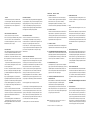
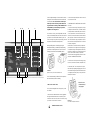
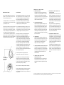
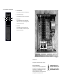
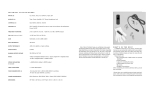
HNICAL
SPECIFICATIONS
TS (6): CD, Tuner, Aux 1, Aux 2/Phono, Tape, SSP
PREAMPLIFIER SP ECIFICATIONS
(Line Level Inputs to Pre Outputs)
PUTS (4): Tape, Preamplifier, Main Power Amplifier,
tereo Headphone Jack
This symbol is intended to alert the user to the
presence of uninsulated “dangerous voltage”
within the product’s enclosure that may be of
INPUT IMPEDANCE: ≥ 40k ohms (line level inputs)
sufficient magnitude to constitute a risk of
electric shock to persons.
TROLS (3): Input Select, Balance, Volume
CHES (5): SSP, Tape/EPL (External Processor
, Mono/Stereo, Mute/Operate, Power On/Off
OUTPUT IMPEDANCE: 150 ohms (minimum required
load: 10k ohms)
FREQUENCY RESPONSE: -0.5dB 20Hz to 90kHz,
-3.0dB 1Hz to 200kHz
COMPLEMENT: 2-6DJ8/6922
ER REQUIREMENTS: 100-120VAC 60Hz (Export
40VAC 50/60Hz) - 400VA
NSIONS: 19" (48 cm) W x 5.25" (13.5 cm) H x 16”
m) D, Knobs extend 3/4" (1.9 cm) forward of panel
This symbol is intended to alert the user to
the presence of important operating and
SIGNAL TO NOISE RATIO: ≤ -90dB (Unweighted ref 1V
@ Pre Out); ≤ -95dB (A-weighted ref 1V @ Pre Out)
maintenance (servicing) instructions in the
literature accompanying the appliance.
THD&N: ≤0.01% 10Hz to 50kHz
(Ref 1V @ Pre Out)
PHASE: Non Inverting
WEIGHT: 38 Ibs, (17.2 kg) - unpacked
GAIN: 15dB (5.7x)
G R ATED AMPLIFIER SPECIFICAT I O N S
POWE R A MPLIFI ER SPECIFICAT I O N S
D POWER: 90 Watts (25.5Vrms) into 8 ohms uous; or 145 Watts (23Vrms) into 4 ohms; both
els driven 20Hz to 20kHz @ <1% THD&N
UENCY RESPONSE: -0.5dB 20Hz to 35kHz
); -3.0dB 10Hz to 95kHz (@ 1W)
AL TO NOISE RATIO: ≤ -95dB (A-weighted ref 80W
power); ≤ -90dB (Unweighted ref 80W rated power)
&N: ≤ 0.1% 1kHz @ rated power,
% 30Hz to 15kHz @ rated power,
8Hz to 23kHz @ rated power
(SSP Input(s) to Main Speaker Output)
RATED POWER: 90 Watts into 8 ohms - continuous; or
145 Watts into 4 ohms; both channels driven; both channels driven; 20Hz to 20kHz @ <0.1% THD&N
FREQUENCY RESPONSE: -0.5dB 10Hz to 40kHz (1W);
-3.0dB 15Hz to 100kHz (1W)
SIGNAL TO NOISE RATIO: ≤ -100dB (A-weighted ref
80W rated power); ≤ -90dB (Unweighted ref 80W rated
power)
THD&N: ≤0.1% 20Hz to 20kHz @ rated power;
SE: Non Inverting
PHASE: Polarity Non-inverting
T IMPEDANCE: 40k ohms (Line level inputs)
INPUT IMPEDANCE: 19k ohms (Power Amplifier Inputs)
39dB
DAMPING FACTOR: ≥100 @ 8 ohms
ITIVITY: 280mV input for rated power, 8 ohms
me control @ maximum)
GAIN: 24dB (16x)
SENSITIVITY: 1.6VRMS input for rated power
We at Sonic Frontiers hope you will derive many years
of listening pleasure with your new Anthem Integrated 2.
This Operating Manual contains important information
regarding the operation and care of the Integrated 2.
Be sure to read this manual carefully and follow these
instructions in order to keep your unit performing and
sounding its best. Please contact Sonic Frontiers if you
have any questions, a Customer Service Representative
will be pleased to assist you.
WHAT’S IN THE BOX?
In addition to the Integrated 2, it’s cover, and the o
ating manual you are presently reading (with associa
inserts and warranty card), there are a few more item
take inventory of before steps are taken to make the
Anthem Integrated 2 operational.
These items are:
• 2 6DJ8/6922 tubes
• a glove for handling the tubes
• a detachable AC power cord
• 18 phillips screws
• a phillips screwdriver
• remote handset
After completing an inventory of these items, proce
to the next steps.
4. Sonic Frontiers, Inc. shall not be responsible in any way
for consequential or indirect damages or liabilities resulting
from the use and operation of the product covered herein
or resulting from any breach of this warranty or any
implied warranty relating to said product.
A
B
During this period, Sonic Frontiers, Inc. will repair or
replace any defective components free of charge. A
Return Authorization Number (RA Number) is required
before any product is returned to our factory for any
reason. This number must be visible on the exterior of the
shipping container(s) for Sonic Frontiers to accept the
return.
C
Units shipped to us without a Return Authorization Number
or without a visible RA Number on the exterior of the shipping container(s) will be returned to the sender, freight
collect.
Units to be repaired by Sonic Frontiers, Inc. must be sent
shipping and insurance prepaid by the original purchaser
in the original packing material. A returned product should
be accompanied by a written description of the defect.
Repaired units will be returned by Sonic Frontiers, Inc.
shipping and insurance prepaid.
All other warranties or conditions either written or implied
are void.
Note: In foreign markets (anywhere outside of Canada and the
USA), the warranty is supplied by the authorized International
Distributor. Exact terms and conditions may vary.
This symbol is intended to alert the user
D
E
F
G
H
I
J
K
presence of uninsulated “dangerous volt
within the product’s enclosure that may b
sufficient magnitude to constitute a risk o
electric shock to persons.
This symbol is intended to alert the user
the presence of important operating and
maintenance (servicing) instructions in th
literature accompanying the appliance.
CONTROL
A
- IN TIME
all audio electronic products, the ultimate sonic
er of the Integrated 2 will not be realized until and
the unit receives a minimum of approximately 70
of signal break-in time (i.e. the Integrated 2 is on
tputting a signal).
This knob is rotated to select a Line Level Input (P).
The Selector Switch is bypassed when the Tape/EPL
(External Processor Loop) mode is selected by
depressing the Tape/EPL-Source button (F), or when
SSP mode is selected by depressing the SSP button (D).
PACKING MAT E R I A L S
Please retain all of the packing material and shipping boxes
for your Integrated 2. They are custom designed to prevent
shipping damage from occurring. Sonic Frontiers, Inc. will
accept no responsibility for any damage occurring to an
Integrated 2 that is shipped in packing material other than
the original Sonic Frontiers packing material.
B
Y INSTRUCTIONS
ation - Although your Integrated 2 generates only nomt in use, be sure that the ventilation slots in the top
ave at least 4” of unobstructed air space above them.
er and Moisture - This product should not be used
water. To prevent fire or shock hazard, do not expose
duct to rain or moisture.
- This product should be situated away from heat
s such as radiators, heat registers, stoves, or other
ces which produce heat.
er Sources - This product should be connected to an
wer source of the proper rated voltage. The original
g container will stipulate the AC voltage this unit can
e with correctly.
ning - A regular dusting with a soft, non-abrasive
ll generally keep the finish of the faceplate and chasing like new. At no time should you allow any liquid to
n contact with the Integrated 2; it may run into the
nic circuitry and cause damage which will not be covder your warranty.
cing - Do not open this product. No user serviceable
side. Refer servicing to an authorized service technician.
Use Periods - The power cord of this product should
ugged from the outlet when left unused for an
ed period of time.
ot remove the Integrated 2 cover while the unit is
connected to an AC power source. Cover screws
all through the ventilation slots and cause electrical
e to the Integrated 2.
DISC LAIME R OF L IABILITY
Under no circumstances does Sonic Frontiers, Inc.
assume liability or responsibility for injury or damages
sustained in the use or operation of this equipment or for
damages to any other equipment connected to it.
Sonic Frontiers, Inc. reserves the right to make design
changes or improvements without the obligation to revise
prior versions. All specifications are subject to change
without notice.
C
1. Warranty applies only to the original purchaser.
2. This warranty is void and inapplicable if the product has
been handled other than in accordance with the instructions in this Operating Manual, abused or misused, damaged by accident, neglect or in being transported, or the
defect is due to the product being tampered with, modified or repaired by anyone other than Sonic Frontiers, Inc.
or an authorized Sonic Frontiers repair depot.
The Infra Red signal from the Integrated 2’s remo
control is received here, to operate the Volume, M
and SSP controls.
H
LED
When the LED is lit the Integrated 2 is “ON”, rece
power.
When the Power Button (K) is depressed the LED
be dimly lit Green. After the power-up delay has
timed-out (approx. 40 seconds) the LED will be li
bright green. Upon activating the SSP button (D),
LED will be lit orange. When in Mute mode the ind
tor LED will flash ON-OFF at approximately 1 seco
intervals.
BALANCE CONTROL
VOL UME C ONTROL
I
D-
This button selects an external Surround Sound Processor
(SSP) input signal. When selected all preamp functions
are completely disabled. The only way to deselect SSP
mode is to press the SSP button a second time.*
E
HEADPHONE INPU T J ACK
The Headphone Jack accepts 1/4” stereo headphone
plugs. Upon insertion of the headphone plug, the main
amplifier outputs are disabled. All other preamp functions remain operational. Removal of the headphone
plug restores the main output signal.
F
J
TAPE /EPL (EXTERNAL PROC ESSOR LO OP)-
system loudspeakers when selected.
* This input also functions as an “Amplifier Only” input.
M U T E - O P E R ATE BU TT ON
When in the OPERATE state, this button will allow
normal function. When in the MUTE state, the mu
signal is prevented from reaching the Outputs (R)
(L). To indicate a muted condition, the indicator L
(H) will flash OFF-ON at approximately 1 second i
vals.
Please Note that Muting does not work wh
SSP Mode.
SO URC E BUTTON
When this button is in the SOURCE position (button is
not depressed) the signal is routed through the
Selector Switch (A) to the Tape/EPL Output (N).
Listening and taping is done in this mode. When the
button is depressed, the source signal is taken from a
tape or processor source through the Tape/EPL Inputs
(O) bypassing the selector switch.
MON O/S TE RE O BUTTON
When in the ON position (button depressed), the
Mono function is enabled. This function sums all
selected input signals together, and directs them
both channels. As long as the button is depresse
left or a right mono signal will be sent to both cha
of the preamplifier. All other preamplifier functions
operate normally.
SSP (SURROUND SOUND PROCESSOR) INPUT BUTTON
NOTE: Unterminated (open) inputs may produce hum from the
3. Warranty does not cover normal maintenance.
INFRA RED RE CEIVER
This knob allows variable control over the Integrated 2’s
output level. Turn it clockwise and the music gets louder!
LIMITED FIVE YEAR W A R R A N T Y
Sonic Frontiers, Inc. warrants to the purchaser that each
Integrated 2 is free of manufacturing defects for a period
of five (5) years from the date of purchase. This five (5)
year limited non-transferable warranty excludes all vacuum
tubes, which we warrant for a period of twelve (12)
months. To receive this warranty, the original purchaser
must complete and mail to Sonic Frontiers, within thirty
(30) days from the date of purchase, the enclosed
Warranty Registration Card. Sonic Frontiers, Inc. will then
validate the warranty to the original purchaser. This warranty is subject to the following conditions and limitations:
G
This knob controls the relative balance of the left and
right channels to compensate for any discrepancies
caused by speaker placement, source imbalance, etc.
Full rotation to the left or right of the center detent will
fully attenuate the left or right channel.
MENT FOR PR OPE R VE NTILAT I O N
t least 4” (15 cm) of clear space above the
ted 2 chassis for proper ventilation, making sure the
slots in the chassis cover remain unobstructed.
e sure that the Integrated 2 is placed on a secure,
nd level surface (not on carpet).
FUNCTIONS
SELECT OR SWITCH
K
ON-OFF BUTT ON
When in the ON position (button depressed), line
age is received by the Integrated 2 circuitry from
AC source. Due to the warm up characteristics o
tubes, it will take 40 seconds for the tubes to pas
signal. It is suggested that the Volume be turned
for this first minute. After the power-up time-out
(approx. 40 sec.) set the desired volume level. W
in the OFF position (not depressed), the Integrate
is not receiving power and is not operational.
L
M
N
O
P
Volume is adjusted through use of the Volume Control (C).
Turning this control clockwise increases the volume level
of both channels. Be sure the Volume Control (C) is
in the fully counter-clockwise position when turning the unit ON or returning to the OPERATE mode
after MUTING, to prevent damage to speakers,
amplifiers or the Integrated 2.
To record from a source, place the Tape/EPL-Source button (F) in the SOURCE position, select the source material
you wish to record via the Selector Switch (A), and commence recording. To play back a tape recording, place the
Tape EPL/ Source button in the TAPE position.
Muting the Integrated 2 is achieved by placing the
Mute/Operate button (J) in the MUTE position (flashing
green LED); the output signal is then cut off. To resume
listening, place the button in the OPERATE position.
2. Ensure that all Input and Output connections are secu
a proper electrical contact.
3. DISCONNECT THE AC POWER CORD, wait 5 minutes
check that:
• A slo-blo fuse, with a rating of 4 Amp/250 V (2 Amp/2
for European and Asian versions), is installed in the fuse
er directly under the removable IEC power cord socket.
• The AC power fuse is intact and has not blown. If the
has blown, the thin metal conductor will have melted an
glass may appear “smoked”. If the fuse has blown, repl
with a fuse of the same rating (4 Amp/250V slo-blo for 1
120 volt countries and 2 Amp/250V slo-blo for 200 to 24
countries). (See Figure 5)
NOTE: Under no circumstances should you replace the
power fuse with one of a higher current rating! Doing so
cause further damage to the Integrated 2 and will also v
the warranty. In addition, your continued protection from
of fire or shock would be seriously compromised.
• Ensure the tubes are plugged firmly into their sockets
described in “INSERTION OF THE TUBES”.
5. Be sure the rest of the system is functioning properly
source unit, cables and connections, loudspeakers etc.)
F I G UR E 3
Alignment of the AC power connector and detachable cord.
6. With tubes, fuses, covers and power cords in place,
that the LED (H) is lighted (glowing light green). If all of t
above troubleshooting steps have been followed and th
is not lighted (remains dark green), contact your dealer
distributor for assistance.
It is recommended that you shut OFF the main power via
the Power Switch (K) when not listening.
Q
R
Note: The fuse is not
TROUBLESHOOTING
accessible when the po
cord is plugged in.
If at any time the Integrated 2 fails to work properly, consult
this checklist:
1. Check that the AC Detachable Power Cord is plugged into
the Integrated 2 Detachable Power Cord Socket (Q) and is
connected to a live source of AC power. For instance, if using
a power bar, check that the bar is turned on.
F I G UR E 4
Fuse location in the Integrated 2 and removal.
WARNING-DISCONNECT THE AC
CONNECTION
L
R TIO N OF THE TU BES
OPERATION
g the screwdriver supplied, remove the cover of
egrated 2. For your convenience, only four to six
screws are installed at the factory.
Before plugging in the Integrated 2, check to see that the
unit is configured for the correct AC line voltage for country of use. The operating AC line voltage is indicated on
the side of the shipping box. If the Integrated 2 is set
incorrectly for the country in which it is to be operated,
contact the dealer or distributor in your area. If the unit is
configured properly, continue with operation.
n handling the tubes, it is recommended that the
gloves provided be worn to prevent skin oils from
ing on the glass surface.
ng the location of the tube sockets in the top view
inspect the tubes for corresponding labels and
gs. Once locations are mapped, take a tube and
the pins, noting the larger space between two of
s (see Figure 2). This space will match with the
Insert each tube into the appropriate tube sockking sure all pins and pin holes are aligned. Do not
he tubes into the sockets. “Rock” the tubes gently
ushing slowly until each tube is firmly seated.
M
N
This input accepts a single-ended RCA input connection from a tape deck or external processor; connect
left channel to left channel and right channel to right
channel. These inputs are activated when the
Tape/EPL-Source button (F) is depressed.
O
TAPE/EPL (EXTE RNAL PRO CESSO R L OOP) OUTPUT
This output connects to the single-ended inputs of a
tape deck or external processor; connect left channel
to left channel and right channel to right channel. This
output always follows the input selection of the
Selector Switch (A).
P
The Integrated 2 is now ready for operation. Power the
Integrated 2 by placing the On-Off button (K) in the ON
position. Upon power-on, the Integrated 2 will be muted
for 40 seconds to allow the circuitry to stabilize, and this
will be indicated by a dim green LED (H).
TAPE /EPL I NPUT
D E TACHABLE AC POW ER CORD SOCKE T
AND F US E HOLDER
Plug the Detachable Power Cord into this socket
Figure 3). The Integrated 2 is factory set for the c
rect operating voltage for the area in which it is s
(see shipping box for voltage setting). If a differen
operating voltage is required, please contact an a
rized Sonic Frontiers or Anthem dealer, distributo
the factory directly.
Two spare fuses have been supplied with your
Integrated 2, along with the fuse in the unit. The f
is not accessible with the detachable power cord
place (see fig. 4). A spare fuse is supplied in the
drawer. Use only the supplied fuses or fuses obta
from your Sonic Frontiers dealer.
SSP/POW ER AMPLI FIE R INPUT
This input accepts a single-ended RCA input connection from an external preamp or SSP Processor; connect left channel to left channel and right channel to
right channel. The signal input at these connections
will bypass all control functions and preamp functions
of the Integrated 2 and will operate only as a power
amplifier. To enable this input, depress the SSP button
(D) on the front panel.*
Connect loudspeakers to the appropriate post as
described in the connection section of this manual.
larger space
two of the pins and
r proper alignment
and socket.
Q
This output connects to the single-ended inputs of
other units such as power amplifiers or a crossover
unit; connect left channel to left channel and right
channel to right channel. The “Pre-Out” jacks allow the
Integrated 2 to be used solely as a preamp. These
outputs are functional at all times.
First check that the Power Switch (K) is in the “Out” position (OFF) and then connect the Detachable Power Cord
to the Integrated 2 AC Power Cord Socket (Q) (see Figure
3). Plug your Integrated 2 into the AC power source.
All remaining connections are made with your favorite
interconnect to or from other single-ended inputs.
Connect source units to the Integrated 2 Inputs (P); l e f t
channel to left channel and right channel to right channel.
If a tape or other line level recording or processing device
is being implemented, connect the left and right audio output of the unit to the corresponding left and right Tape/
EPL Input (O) of the Integrated 2. Also connect the left
and right Tape/EPL Outputs (N) on the Integrated 2 to the
corresponding left and right audio inputs of the external
device. The outputs from a Surround Sound Processor
(SSP) can be connected to the SSP input, left output to left
input, right output to right input.
FUNCTIONS
PREAMPLIFIER OUTPUT
R
LO UDS PEAKER CO NNEC TIO N POS TS
The binding posts on the Integrated 2 are configu
to allow bare wire ( ≤ 12 awg) or spade lug loudsp
connections. These binding posts are CE approve
and do not allow the use of banana plugs, as the
nector barrel has been plugged with a plastic inse
countries where banana plugs are allowed, these
inserts may be removed.
Loudspeakers with a nominal impedance of 4 to
ohms are suitable for use with the Integrated 2. I
have any concerns about the suitability of your lo
speakers, consult your speaker data sheet or ma
your dealer, or Sonic Frontiers Service Represent
directly.
LINE L EVE L INPUTS FOR CD , T UN ER
AND AUXILI ARY SOURCE S
A line level single-ended source connection may be
made to these 4 sets of RCA connectors; connect
left channel to left channel and right channel to right
channel.
Select a desired source through the Selector Switch (A).
E 2
Balance is adjusted through use of the Balance Control (B);
turning it left and right will adjust the left and right levels.
The center detent is an indicator for equal, or balanced, left
and right levels.
* In this mode, the Integrated 2 may be used as a separate pre-amp and power amp, eg. an electronic crossover may be inserted be
“Pre-Out” and “SSP / Power-In”, or the “Pre-Out” jacks could be used in a “Bi-Amp” system.
OTE
CONTROL
FUNCTIONS
S
VOLUME C ONTR OL UP
This button will increase the volume of the Integrated 2.
T
VOLUME CONTROL D OWN
This button will decrease the volume of the Integrated 2.
S
U
T
V
U
MUTE BUTTO N
This button will Mute the outputs of the Integrated 2
until the button is pressed again. This Muting is indicated by the flashing of the LED (H).
V
SSP BUTT ON
This button will select an external Surround Sound
Processor or Preamplifier as the input, and bypass all
Integrated 2 Preamp functions.
V1
V2
FI G U RE 1
SETTING UP
The Integrated 2 comes with two (2) tubes, as follows:
6DJ8/6 92 2 PR EAMP TUBE S
These tubes perform the line level preamplifying function of
the Integrated 2. The preamplifier stage of the Integrated 2
provides 15 db of gain. The 6DJ8/6922 tubes may also be
replaced with matched pairs of 7308 tubes.
The tubes are labeled V1 & V2. Place each tube in the corresponding position according to figure 1 above.
WARNING-DISCONNECT THE AC
DETACHABLE P O W E RC O R D FROM
INTEGRATED 2 AND WAIT 5 MINUT
BEFORE REMOVING COVER, OR TU
A NTH EM IN TE GR AT ED 2
E S I G N E D
A N D
M A N U F A C T U R E D
B Y
S O N I C
F R O N T I E R S
I N T E R N A T I O N A L
O P E R AT I N G M A N U A L