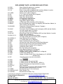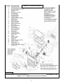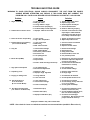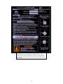
1
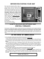
INSTALLATION & OPERATION MANUAL MODEL NUMBERS: 25-PDV 55-SHP22 55-TRP22 Thank you for purchasing this product from a fine line of heating equipment. We wish you many years of safe heating pleasure with your new heating appliance. Save These Instructions. IMPORTANT: IF YOU HAVE A PROBLEM WITH THIS UNIT DO NOT RETURN IT TO THE DEALER. CONTACT TECHNICAL SUPPORT @ 1-800-245-6489. Mobile Home Use: These freestanding pellet units are approved for mobile home or doublew ide installation w ith outside combustion air hook-up. See “Flue System” section of manual. Mobile home installation should be in accordance w ith the Manufactured Home and Safety Standard (HUD), CFR 3280, Part 24. WARNING: Do Not Install in Sleeping Room CAUTION: The structural integrity of the mobile home floor, w all and ceiling/roof must be m aintained. Please Note the Following Precautionary Statements: NOTE: WE DO NOT RECOMMEND PELLET STOVES AS YOUR ONLY SOURCE OF HEAT. England’s Stov e Works highly recommends the use of smoke detectors and Carbon Monoxide detectors w ith any hearth product, including this unit. Follow all manufacturer’s instructions w hen using smoke or Carbon Monoxide detectors. CAUTION: Please read this entire manual before installation and use of this pellet fuel burning room heater. Keep children, furniture, fixtures, and all combustible materials away from any heating appliance. Refer to this owner’s manual for all clearances to combustible materials. WARNING: USE OF OUTSIDE AIR IS MANDATORY WIT H THIS UNIT. DO NOT OPERATE UNIT WITH HOPPER OPEN. LID MUST BE SHUT AND TIGHTLY SECURED. DO NOT OPERATE WITH DOOR OPEN SAFETY NOTICE FAILURE TO FOLLOW T HESE INST RUCTIONS COUL D RESULT IN PROPERTY DAMAGE, BODILY INJURY OR EV EN DEAT H. FOR YOUR SAFETY AND PROT ECTION, FOLLOW ALL THE INSTALLATION INST RUCTIONS. CONTACT YOUR LOCAL BUIL DING OR FIRE OFFICIALS FOR RESTRICTIONS AND INSTALLATION INSPECTION REQUIREM ENTS (INCLUDING PERMITS) IN YOUR AREA. Questions? Need Parts or Options? www.englanderstoves.com Rev. 6/11 A letter from our Technical Support department: Thank you for purchasing this fine product from England’s Stove Works! England's Stove Works was started, and is still owned by, a family that believes strongly in a "Do It Yourself" spirit – that’s one reason you found this product at your favorite “Do It Yourself” store. We intentionally design and build our stoves so that any homeowner can maintain his or her unit with basic tools, and we're always more than happy to show you how to do the job as easily and as inexpensively as possible. From our free, downloadable service sheets; to our Pellet Service Video; to our new "wizard-style," click-through Troubleshooting guide on our web site, we have always tried to help our customers stay "heat-ready," especially when oil and electricity prices continue to skyrocket. Please look at our vast Help section on our web site and call our Technical Support department at (800) 245-6489 if you need any help with your unit. We are nearly always able to help “walk you through” any repairs, problems or questions you may have. PLEASE NOTE: While information obtained on our web site and through our 800 number is always free of charge, there will be a service charge incurred with any “on-site” repairs or maintenance that we may arrange. Wishing you years of efficient, quality and “comfy” heating, England’s Stove Works Technical Support Department www.englanderstoves.com (800) 245-6489 IF YOU HAVE A PROBLEM WITH THIS UNIT DO NOT RETURN IT TO THE DEALER. CONTACT TECHNICAL SUPPORT at 1 (800) 245-6489. 2 BEFORE RE-STARTING YOUR UNIT Every time before pressing “ON” to start your unit – Be sure to remove all ashes (burnt or partially burnt) from your burn pot area! Wearing protective gloves and w ith the unit cool, remove the Wear Plate and dump the ashes, ensuring that the air holes are clear from debris. Also be sure to follow all other maintenance instructions as outlined in your Ow ner’s Manual and the Instructional DVD included w ith the unit. Failure to remove ashes from this area before each burn can cause smoke-back and serious damage to your stove, and can void your w arranty. We will not be held responsible for poorly maintained units, including excess ash in the burn pot area. Burn Safe and Burn Clean – Clean the burn pot area daily! A NOTE ON COLD AIR RETURNS AND CENTRAL FURNACES Some homes, including the modern, air-tight homes that are w ell-insulated, create a negative draft that could cause smoke to be released from your unit, especially if it is too close to your home’s Central Furnace. If you install your stove in the same room as the Cold Air Return from your home’s Central Furnace, you must place your stove at least 20 feet (20’) from the Cold Air Return. We recommend you open an outside w indow slightly, and never close the door that leads from this room to the rest of your home. IN THE EVENT OF SMOKE-BACK 1. If you see smoke coming out of your unit into the room due to a power failure, DO NOT OPEN THE HOPPER OR DOOR TO YOUR UNIT!! Rem ain calm . Open the nearest outside door and w indows and wait for all signs of smoke to clear (at least one hour, although the s moke should dissipate quickly once the door and w indow s are opened). When pow er is restored, press the ON button to restart your unit, and let the unit run for at least 30 minutes. -- If you see any further signs of smoke-back, press the OFF button and call Technical Support at (800) 245-6489 before restarting your unit, as damage could have occurred due to the pow er failure. -- If you see no more signs of smoke-back, press the OFF button and w ait for your unit to completely shut dow n and cool dow n, then clean the burn pot area before restarting your unit (see “Before ReStarting Your Unit,” above). 2. If you see smoke coming out of your unit into the room and the power has not failed, DO NOT OPEN THE HOPPER OR DOOR TO YOUR UNIT!! Rem ain calm . Immediately press the OFF button, open the nearest outside door and w indows and w ait for all signs of smoke to clear (at least one hour, although the smoke should dissipate quickly once the door and w indows are opened). Do NOT restart your unit before calling Technical Support at (800) 245-6489. Please call Technical Support at (800) 245-6489 w ith any questions. England’s Stove Works, Inc. 3 IMPORTANT INFORMATION 1. Check local installation codes for your area. Call your Homeow ner’s Insurance representative for inspection of your stove’s installation. 2. Read and comply w ith the instructions in this manual. 3. This unit should be tested (dry run) before loading pellets for 20 minutes. The stove should automatically shut itself off after the 20-minute dry run. 4. Your stove is designed to burn Wood Pellets only. Burning pea coal, cherry pits, or anything other than w ood pellets w ill void your w arranty. Pellets w ith high ash content w ill burn dirty and require the unit to be cleaned more often. This unit is designed for use w ith ¼” diameter pellet fuel. Using pellets longer than 2” can bind the auger and require frequent manual removal. 5. Be sure your pellets are not damp or w et. Keep saw dust out of the unit. 6. Use three-inch (3”) U.L.-approved PELLET V ENT TWIST-LOCK PIPE w hen installing this stove and follow the manufacturer’s specif ications for installation and clearances (w e highly recommend Simpson Dura-Vent pellet tw is t-lock pipe) (AC-3000 kit). For installations over 4000 ft. above sea level the exhaust should be vented with 4"pellet vent pipe (AC-3100 kit). Even though this pipe interlocks, it is a good idea to seal all connections w ith high temperature silicone (AC-RTV3). Use at least three screws to secure the pipe to this unit’s exhaust blower. Also, if you do not use U.L.-approved tw ist-lock pellet pipe, be sure to use U.L.-approved Pellet Vent pipe, and fasten each joint of the pipe w ith at least three screws. Outside combustion air is mandatory for these units to w ork properly. Make this connection using a 1 7/8” I.D. metal pipe (steel, aluminum or copper) and coupler. Be sure to secure the pipe to the unit w ith a clamp or aluminum tape. The outside end should be covered (screened) to prevent any foreign matter from entering the system. Try to keep the number of bends in this pipe to a minimum. Our Part Number PU-OAK (Outside Air Kit w ith flex pipe) can be used. NOTE: If an older unit, measure the opening to deter mine w hat size pipe to use. NOTE: If the total run of the intake air connection exceeds 6’, use 3” metal pipe and coupler instead. 7. Regularly inspect the burn pot area and, if any crust forms, remove it w ith a poker. 8. The ash in the burn pot should be removed regularly, depending on your burn rate. The area to the right and left of the burn pot is for ash storage; keep the air holes in the burn pot clean for a more efficient burn. Check your exhaust system frequently. Refer to “Ash Removal and Disposal” section. 9. Keep pellets and all other combustible mater ials a safe distance from the unit. 10. This unit w ill require floor protection if installed on a combustible surface. The minimum floor protector for the 25-PDV should give at least one inch (1”) of protection at the rear, four inches (4”) on each side, and six inches (6”) minimum in the front of the unit. 11. Horizontal runs should not exceed four feet (4’) w ith a maximum vertical flue height of thirty five feet (35’). At fifteen feet (15’), the pipe should be increased to four inch (4”) pellet vent pipe. 12. This unit should be turned off and allow ed to cool prior to cleaning. Any ashes should be kept in an airtight metal container and not disposed of until they are completely cooled. 13. Read the instructions thoroughly, including instructions concerning the digital control board, and save them for future reference. 4 14. Do not allow paint, chemicals or construction dust on or near your unit. Do not allow liquid or ANY foreign materials on or inside your unit. Shut your unit dow n and cover it when painting, construction or similar activity is taking place. Wipe and clean your unit after any construction is done in your home, or if any foreign material gets on or inside your unit. You may also need to remove the rear and side cover plates to your unit (unplug unit first) and vacuum and clean the motors and inside of your unit. 15. Improper gasket maintenance, including failure to replace gaskets, can cause air leaks resulting in smoke-backs. 16. Remember that, as w ith any appliance, there is user responsibility involved, including installation, operation and maintenance of this product. Be sure to check local codes, and call Technical Support at (800) 245-6489 if you have any questions. 17. Be sure to follow the directions of all m anufacturers of third party products that you use, including exhaust pipe, etc. Never use gasoline, lantern fuel, charcoal lighter fluid, diesel fuel or any other flammable liquid to start the fire. If you m anually start your unit, recommended fire starter m aterials are: Wax-im pregnated w ood chips, cardboard cubes or firestarter chips designed for pellet stoves (see section on Manually Starting Unit). Follow any m anufacturer’s directions for these products, and NEV ER place any firestarter on any hot surface or hot coals. Never apply any firestarter products of any kind to a hot surface or hot coals. 18. Basement Installation: We recommend basement installation be performed only by a professional installer. For basement installations, a 3” (three inch) pipe and coupler must be used for Outside Combustion Air, and a minimum clearance of 3’ (three feet) must be maintained from the ground to the pellet vent exhaust pipe outside the dw elling. Keep in mind that each elbow used reduces draft by 15%; it is good practice to add 3’ (three feet) of vertical rise for each elbow used. Example: After the 2nd elbow used, have 6’ (six feet) of vertical rise before terminating your vent pipe. UNIT PREPARATION 1. Attach the spring handle to the door by turning it counterclockw ise. Im portant: Also check hopper latches – m ust be tight so that the top is sealed to prevent back-burn. 2. Test your 110-volt outlet for current and then plug in the unit. (We highly recommend a surge protector for our pellet unit, as the control panel is electronic). 3. It is important to note that this stove is equipped w ith a dual auger system. The top auger runs inter mittently and drops pellets to the bottom auger; the bottom auger runs constantly and simply pushes the pellets forw ard to the burn pot. The control board (“Heat Range”) setting determines the top auger feed rate. 4. The stove has a digital read-out control board and is started by pressing the “ON” touch pad. This w ill start the upper auger, bottom auger and exhaust blow er. The room air blow er will start later as the stove reaches the pre-set blow er temperature (see “Control Board” section for further explanation). 5. Check to be sure both augers and the exhaust blow er are operating before connecting the unit to the flue system. Be sure to “dry run” your unit for 20 minutes before connecting it to the flue (it should stop automatically after 20 minutes). Visit our w eb site at www.englanderstoves.com for helpful information, frequently asked questions, parts/accessory orders and more! 5 Proper Impingement (Baffle) Plate Placement in Pellet Stove Firebox Occasionally in shipping, the impingement (baffle) plate may shift out of its proper position. If this is the case w ith your stove, follow these instructions to return the plate to its proper position. 1. Remove the plate from the stove, holding the plate by its tab handle, w ith the cutout notch facing upw ards. 2. Turn the notched end into the doorw ay (as shown above), and lift the plate up to allow the bottom of the plate to fit in the doorw ay. 3. Let the bottom of the plate rest on the firebox, and then push the bottom of the plate flush against the back w all of the firebox. At this point, the plate w ill lean forw ard (tow ard the front of the stove) slightly, and w ill come in contact w ith the front of the stove above the door. 4. Finally, center the plate on the firebox, so that it w ill be centered above the fire w hen the stove is in operation. Technical Support: (800) 245-6489 www.e nglande rstove s.com IMPORTANT NOTICE: This unit must be properly installed to prevent the possibility of a house fire or “smoke-back.” The instructions must be strictly adhered to. Do not use makeshift methods or material which may compromise the installation. Your unit requires periodic maintenance and cleaning (refer to manual). Failure to maintain your unit may lead to a variety of problems, including but not limited to smoke spillage into the home. England’s will not be liable for consequential or indirect damages to property or persons resulting from the use of this product. Visit our w eb site at www.englande rstoves.com for helpful information, frequently asked questions, parts/accessory orders and more! 6 FLUE SYSTEM Caution: Follow the pipe m anufacturer’s installation instructions and directions for passing through com bustible w alls and ceilings. Be sure to check local codes in your area. NOT E: See the installation drawing later in this manual (Illustration 1). This unit is equipped w ith a negative draft system that pulls combustion air through the burn pot and pushes the exhaust air out of the dw elling. If this unit is connected to the flue system other than the w ay explained in this manual, it w ill not function properly. For any of these installations, keep in mind that each elbow used reduces draft by 15%; it is good practice to add 3’ (three feet) of vertical rise for each elbow used. Example: After the 2nd elbow used, have 6’ (six feet) of vertical rise before terminating your vent pipe. Pellet Vent Pipe The UL approved pellet vent pipe that w e recommend is a tw ist lock system; how ever, it is still recommended that high temperature silicone (AC-RTV3) be used at each joint. England’s Stove Works recommends the use of Simpson Dura-Vent tw ist-lock pipe (AC-3000 kit) (if you use other pipe, consult your local building codes and/or building inspectors, and secure each joint w ith at least three screws—see Important Information, above). Do not use “B” vent gas pipe or galvanized pipe with this unit. The pellet pipe is designed to disassemble for cleaning and should be checked several times during the burning season — pellet vent pipe is not furnished w ith the unit and must be purchased separately. For installations over 4000 ft. above sea level the exhaust should be vented w ith 4"pellet vent pipe (AC-3100 kit). Do not install a flue dam per of any kind in this system , and do not connect this unit to a flue system serving another heating appliance. Through the Wall To vent the unit through the w all, connect the pipe adapter to the exhaust motor adapter. If the exhaust adapter is at least eighteen inches (18”) above ground level, a straight section of pellet pipe can be used to initially pass through the wall (see Illustration 1). Your dealer or our factory should be able to provide you w ith a kit that w ill handle most of this installation, w hich w ill include a w all thimble that w ill allow the proper clearances through a combustible w all. Once outside the structure, a three-inch (3”) clearance should be maintained to the outside w all and a clean out tee should be placed on the pipe that extends through the w all. We recommend a minimum of three feet (3’) of vertical pipe w ith a 90-degree turn aw ay from the house. At this point, a one-foot (1’) section and horizontal cap w ill complete the installation (see Illustration 1). A w all strap should be placed just below the last 90-degree section to make the system more stable. If you live in an area that has heavy snowfall, it is recommended the installation be taller than three feet (3’) to get above the snow drift line. The same type installation can be used if your stove is below ground level by adding the cleanout section and vertical pipe inside until ground level is reached. How ever, w e recommend basement installation be performed only by a professional installer. For basement installations, a 3” (three inch) pipe and coupler must be used for Outside Combustion Air, and a minimum clearance of 3’ (three feet) must be maintained outside the dw elling from the ground to the Pellet Vent Exhaust Pipe. The through-the-w all installation is the least expensive and simplest installation. In a throughthe-w all installation you should be mindful of the snowdrift line, as well as dead grass and leaves. We recommend a three foot (3’) minimum vertical rise on the inside or the outside of the dw elling. Call (800) 516-3636 to inquire about the AC-3000 Through-the-Wall Kit or the AC-3100 High Altitude Kit. 7 Through the Ceiling When venting the stove through the ceiling, the pipe is connected the same as through the w all, except the clean out tee is alw ays on the inside of the house, and a 3” adapter is added before the clean-out tee. You must use the proper ceiling support flanges and roof flashing supplied by the pipe manufacturer -- follow the pipe manufacturer’s directions and Illustration 1 in this manual. It is important to note that if your vertical runs of pipe are more than fifteen feet (15’) at this point, the pellet vent pipe should be increased to four inches (4”) in diameter. Do not exceed four feet (4’) of pipe on a horizontal run, and do attempt to use the least number of elbows in the flue system. If an offset is used it is better to install a 45-degree elbow whenever possible. Please remember, installing elbows may inhibit your draft by up to 15% per elbow. Existing Flue System If you are replacing a w ood stove with a pellet unit the chimney or pipe should be thoroughly cleaned before proceeding w ith the installation. The flue system should be either masonry or a UL approved pre-manufactured Class A flue system. The flue thimble should be either six inches (6”) or eight inches (8”) and the proper reducer (6” to 3” or 8” to 3”) can be purchased at your local dealer. Connect a three inch (3”) tee w ith clean-out to the pipe adapter -- seal this w ith high temperature stove cement, then extend your pipe to the installed reducer at the thimble. If the thimble is in the ceiling, the pipe w ill go straight up, but if the thimble is in the w all another 90-degree elbow will be required to make the connection. Outside Air (Outside Combustion Air Intake) Outside air is mandatory for this unit to operate properly. This unit has been designed and tested w ith this connection, because so many homes are airtight and there is not adequate combustion air available inside the dw elling. The air intake pipe is located on the bottom side of the burn pot (from the rear) and measures 1 ½” inside diameter ( I.D.). The connection can be made with a metal 1 7/8” I.D. coupler and pipe (see “ Important Information” section of manual), and should exit through the w all. Be sure to secure the pipe to the unit w ith a clamp or aluminum tape. The outside end of the pipe should be covered (screened) to prevent foreign matter from entering the system. Our Outside Air Kit (Part Number PU-OAK) can be used. If the unit is located below ground level, you w ill need to run the pipe up and then outside the dw elling. NOTE: If the total run of the connection exceeds 6’, if more than 2 elbow s are used, or if a basement installation, use 3” metal pipe (and coupler) instead. Note: If an older unit, measure the opening to deter mine w hat size pipe to use or couple to. Mobile Home Installation Secure the heater to the floor using the tw o holes in the pedestal. If the unit is on a combustible surface, you will need to drill matching holes in the floor protection that you choose (see Floor Protection section). Do not disturb the structural integrity of the home, and be sure the unit is permanently electrically grounded to the chassis of your home. Remember that outside combustion air is mandatory, and not to install the unit in a sleeping room of the home. WARNING: DO NO INSTALL IN SLEEPING ROOM CAUTION: THE STRUCTURAL INTEGRITY OF THE MANUFACTURED HOME FLOOR, WALL AND CEILING/ROOF MUST BE MAINTAINED. Im portant Notes Concerning Installation: *IMPROPER INSTALLATION: The m anufacturer will not be held responsible for dam age caused by the m alfunction of a stove due to im proper venting or installation. Call 800-245-6489) and/or consult a professional installer if you have any questions. IMPORTANT: Improper hook-up (too much pipe, too many elbows, etc.) will cause the unit not to operate. Call Technical Support (800-245-6489) if you have questions about your hook-up or if your unit will not operate. 8 Freestanding Pellet Installation Caution: Follow the pipe m anufacturer’s installation instructions and directions for passing through com bustible w alls and ceilings. Check local codes in your area. Illustration 1 Our Part AC-3000 is acceptable for through-the-wall installation. (AC-3100 for 4000+ ft. installations.) Must have minimum 3” adapter before tee for longer run. For shorter run (such as Masonry Connection below), tee alone is acceptabl e. Basement Installation should be performed by professional installer. Use 3” metal pipe and coupler for Outside Combustion Air. Minimum 3’ clearance from ground to the P ellet Vent Exhaust P ipe. Masonry Connection 1. 2. 3. 4. 5. 6. If 3” flue pipe exceeds 15’ in length, increase to 4” flue pipe for remaining flue connections. Total flue length should not exceed 35’. Horizontal run not to exceed 4’. Floor protector must extend 6” from front of unit, 4” from sides and 1” from rear. If the total run of outside air connection exceeds 6’, if more than 2 elbows are used, or if a bas ement install, use 3” metal pipe (and coupler) instead. Outside Air is mandatory for proper safe operation. FLOOR AND WALL PROTECTION Floor Protection If your floor is constructed of a non-combustible material such as brick or concrete, there is no need for floor protection. If the floor is constructed of a combustible material such as hardwood, linoleum, or carpet, then you w ill be required to use floor protection betw een the unit and the combustible. The protection should be U.L. approved or equivalent and must be large enough to provide a minimum of one inch (1.0”) behind, four inches (4.0”) on both sides of the stove and at least six inches (6.0”) in the front of the unit. This floor protection is intended as spark and ember protection only, therefore it need only be non-combustible (there is no required R value). INSTALL VENT AT CLEARANCES SPECIFIED BY THE VENT MANUFACTURER Wall Protection From the rear and the sides of this stove only six inches (6”) of clearance is required to paneling, w allpaper or drywall. The pellet vent pipe w ould require the standard three inches (3”) clearance, or as recommended by the manufacturer. Normally additional w all protection is not required w ith this type unit. 9 OPERATING INSTRUCTIONS CAUTION: DO NO T OPERATE WI TH THE DOOR OPEN. If door is left open (approximately) tw o minutes, unit will stop feeding and fire will go out. Do not burn trash (paper bags, etc.) in this unit. This stove has an induced draft system and is designed to operate continuously, as frequent shutdow n is not required. The digital control board operates the unit w ith a time delay-relay system; this system controls the top auger feed rate by operating for a predetermined number of seconds while the bottom auger runs constantly. The setting of the “Heat Range” touch pad w ill control the heat output and the amount of pellets the unit w ill burn (see “Control Board” section and Illustration 2). Note: This stove is using solid fuel and w ill not restart automatically. * NOTE: Blower Speed will automatically be adjusted to the desired Heat Range that you select. Horizontal Feed System This unit has a top and a bottom auger that are separated by four inches (4”); a 1-RPM motor drives each auger. The top auger inter mittently drops pellets to the bottom auger tube, and the bottom auger pushes the pellets forw ard to the burn pot. This helps prevent build-up of fuel in the bottom auger tube. As pellets enter the burn pot the combustion air is draw n across the fuel. START- UP PROCEDURE Caution - Never use gasoline, lantern fuel, charcoal lighter fluid, diesel fuel, or any other flamm able liquid to start the fire. 1. Be sure the hopper is clean and free from foreign materials. Be sure there is current at your outlet (w e do recommend a surge protector w ith our unit). 2. Before your first fire dry run your unit (with no pellets in the hopper) for 20 minutes. Press the “ON” button to begin the dry run. After the 20 minute dry run, the control board will return to “OFF.” An error code w ill appear in the Heat Range and the Blow er Speed windows as “E-2,” w hich means the unit failed to start normally. After this code is received and you are sure the unit is w orking properly, fill the hopper w ith w ood pellets. Do not allow any part of the bag or any foreign material in the hopper, as this may jam the augers. Ensure that all pellet matter is cleared from the hopper lid gasket, make sure the hopper lid latches and the door of the unit are securely closed and press the “ON” button; this w ill clear the error code and restart your unit. Autom atic Start-Up When the “ON” button is pressed from a cold start, the unit is in “Start-Up” (after 3 seconds, there w ill be an “S U” in the Heat Range and Blow er Speed w indows to verify this). While in this mode, the unit has a preset heat range and w ill remain in this mode for 20 minutes to prevent the unit from over-firing. During this start-up period you can set the Control Board at the setting you desire; after the start-up is complete, the unit w ill operate at the user setting. Manually Starting Your Unit In the event the Auto-Start does not initiate, you may manually start your unit. To manually start your unit, first clean any pellets out of the burn pot (to prevent over-feeding). Place a handful of new pellets in the burn pot, then spread a s mall amount of pellet fire starter over the pellets and ignite them. After the pellets ignite, close the door to your unit and press the “ON” button (if the door is closed before the pellets fully ignite, the Exhaust Blow er could put out the fire). Recommended fire starter materials: Wax-impregnated w ood chips, cardboard cubes or firestarter chips designed for pellet stoves. Follow any manufacturer’s directions for these products, and NEV ER place any firestarter on any hot surface or hot coals. Never use gasoline, lantern fuel, kerosene, charcoal lighter fluid, diesel fuel or any other flammable liquid to start the fire. Do not use the manual startup method if the igniter is w orking. NEV ER place firestarter near the igniter. If you have continued problems w ith the Auto-Start Igniter, call Technical Support. 10 E-Codes “E- Codes,” or Error Codes, are codes that w ill appear in the windows of the Control Board if your unit experiences problems. If first attempt to reset your unit by pressing the “ON” button (only display any E-Code(s), please contact Technical Support at attempting to restart your unit. Heat Range and Blow er Speed you receive any of these codes, once). If the unit continues to (800) 245-6489 before further 1. E-1 = Vacuum Loss 2. E-2 = Fail to Start 3. E-3 = Over Temperature Limit NOTE: “ E-0” indicates “No Error” First Fire: Adjust the “Heat Range” to a “5” setting and allow the stove to burn in this m anner for at least three (3) hours. This will allow the unit to “cure out” as the paint and the oils from the m anufacturing process burn off. We recommend you open doors and windows in your dwelling during this process. Subsequent Cold Starts: In a cold start situation, the unit should be operated at a “5” setting until the room air blower begins to operate. NOTE: The start-up cycle for this unit w ith the Auto-Start Igniter is 13 m inutes. Press the “ON” button only once on start-up. Pressing the “ON” button a second time during the start-up cycle w ill cause the start-up cycle to begin again. IM PORTANT: If the unit fails to start properly, or procedure, open the closest outside natural draft BEFORE opening the any smoke to exit through the external does not properly complete the Shut- Dow n door and a w indow to elim inate the home’s stove’s door or hopper lid. This will allow air hook-up instead of spilling into the home. SHUT- DOWN PROCEDURE WARNING: NEVER SHUT DOWN THIS UNIT BY UNPLUGGING IT FROM THE POWER SOURCE. Refer to the follow ing instructions: Press the “OFF” touch pad to put the stove in the “Shut-Dow n” mode. There w ill be an “S D” in the Heat Range and Blow er Speed w indows while the unit is shutting dow n to verif y this. At this time the red light above the “OFF” pad w ill illuminate. When the “OFF” pad is touched the top auger w ill instantly stop feeding pellets to the bottom auger tube, but the room air blow er, exhaust blow er and bottom auger w ill continue to operate. When the internal temperature drops to 95 degrees the room air blow er w ill cease to operate, and w hen the internal temperature drops to 90 degrees the bottom auger and exhaust blow er will stop. The red light w ill then shut off and the entire stove w ill be shut dow n. The hotter the unit is operating, the longer it w ill take for the stove to complete the Shut-Dow n cycle. Note: The unit w ill exit the Shut- Dow n cycle if you press any buttons during Shut-Dow n. Note: If the room temperature stays above 70 degrees the stove will remain in the Shut Dow n mode for 60 minutes, regardless of the temperature reading at the heat sensor. If the stove stays on longer than 60 minutes the unit w ill automatically turn off. 11 DAILY OPERATION Refueling the Unit Alw ays press the “OFF” touch pad before refueling. This stove has a (approximately) 60-lb. hopper, and should be refilled w hen the hopper level drops to three or four inches. Note: The hopper lid w ill be w arm; therefore, you should alw ays use some type of hand protection. NEV ER place your hand near the auger w hile the stove is operating. Note: Alw ays ensure that all pellet matter is cleared from the hopper lid gasket before closing. Be sure to close and latch hopper securely before re-firing. Do not operate this unit w ith the hopper lid open or unsecured. Power Outage If the pow er to the unit is interrupted for approximately three minutes or less, the unit w ill resume operation w hen power is restored according to the follow ing table: Unit’s State Before Power Loss ON Start-Up Shut-Dow n OFF State When Power Returns Start-Up Start-Up Shut-Dow n OFF If the pow er is interrupted for more than (approximately) three minutes, the unit w ill be “OFF” when pow er returns. Important: Do NOT open the hopper lid or the door to the unit during power outage. Open the closest outside door and a w indow to elim inate the home’s natural draft. Wait for pow er to be restored and then press the “ON” button to re-start the unit, if necessary. We highly recommend the use of a surge protector w ith your unit, as pow er surges and failures can affect the operation of any electrical appliance. We do not recommend leaving home w ith the stove on the higher heat ranges; it is recommended that the stove be left on the low er heat ranges (Heat Range setting 1 or 2). NOT E: Remember: 1) It is very important for the unit to be vented properly (see instructions on Outside Air), as the natural draft is needed to clear the smoke from the stove. 2) Do not open the hopper lid (or the unit’s door). This may cause fire to burn in the hopper. Fuel Outage If the unit should run out of pellets, simply reload the hopper and press the “ON” button (only once) to re-start the unit. If the unit runs w ithout pellets, after one hour the unit w ill shut dow n. NOTE: Even if flames are visible inside the fire box alw ays press the “ON” button to ensure that your unit w ill restart. Com bustion Blow er Failure If the Combustion (exhaust) Blow er should fail on this unit, a Vacuum Shut-Dow n Sw itch will automatically stop the stove. This w ill shut your unit completely off, and there w ill be an “ E-1” code in the Heat Range and Blow er Speed windows on the Control Board. At this point you will need to contact Technical Support at (800) 245-6489. NOT E: It is very important for the unit to be vented properly (see instructions on Outside Air), as the natural draft is needed to clear the s moke from the stove. 12 NOTE: The instructions below concerning the cleaning of the burn pot and wear plate area are especially important to the function of your stove. Failure to follow them regularly can result in burn-back and can damage your unit and/or void your warranty. ASH REMOVAL AND DISPOSAL IMPORTANT: While the am ount of ash generated by this unit is not excessive com pared to log-burning w oodstoves, keeping the unit clean and free of ash is essential for peak perform ance. Too m uch ash build-up hampers airflow and reduces the unit’s efficiency, and can cause smoke-back. Follow these directions at least as frequently as the schedule below, or more often if needed. Daily Ash Maintenance Press the “OFF” touch pad and allow the stove to burn for five (5) minutes prior to opening the door. A long-handled screwdriver or long-handled putty knife can be used to scrape off any build-up or crust in the burn pot area. This can then be pushed to the left or right into the ash storage area. Sem i-Weekly Ash Removal Tw ice each week: Shut the unit down by pressing the “OFF” pad and allow ing the unit to go through the complete Shut- Dow n cycle. Allow the unit to completely cool dow n and then remove the ashes w ith a scoop. The ashes should be placed in a non-combustible container w ith an airtight lid and should alw ays be placed on a non-combustible surface or on the ground until completely cooled and free of hot cinders. Bottom Auger Tube Once the ash is removed, the burn pot should be given a thorough inspection. Remove and clean the burn pot w ear plate (refer to the exploded diagram in the rear of this manual – Illustration 6, and the closeup diagram show n here), and remove any ash buildup in the area below the wear plate. Also, be sure Illustration 2 there are no ashes or obstructions in the tube under the w ear plate. Check for any build-up in the front of the burn area. Clean out all air holes (if necessary a 1/8” drill bit can be used) --these air holes should be kept clean, as they supply combustion air under and around the pellet fuel. The burn pot assembly should also be thoroughly cleaned, including the feed auger and feed tube. When replacing the w ear plate, ensure that it lies flat in the firebox and no gaps (from ash residue) are under it. IMPORTANT: Ash build-up under the wear plate can cause the unit to m alfunction. Disposal of Ashes Ashes should be placed in a metal container with a tight fitting lid. T he closed container of ahses should be placed on a noncombustible floor or on the ground, well away from all combustible materials, pending final disposal. If the ashes are disposed of by burial in soil or otherwise locally dispersed, they should be retained in the closed container until all cinders have been thoroughly cooled. Soot and Fly Ash: Formation and Nee d for Removal The products of combustion will contain small particles off fly ash. The fly ash will collect in the exhaust venting system and restrict the flow of the flue gases. Incomplete combustion, such as that which occurs during startup, shutdown or incorrect operation of the room heater will lead to some soot formation which will collect in the exhaust venting system. T he exhaust venting system should be inspected at least once every year to determine if cleaning is necessary 13 Monthly Ash Rem oval The large baffle plate (12-5/8” x 9-3/8”) that rests above and behind the burn pot (refer to the section on “Proper Impingement Plate Placement” and the exploded diagram in the rear of this manual – Illustration 6) should be removed monthly. This can be done by lifting up the plate and pulling it out. The area behind the plate should then be cleaned thoroughly, and the plate placed back in the original position. Use a screwdriver or chisel and break any creosote build-up in the front of the unit, w here the pellets are fed into the burn pot from the Bottom Auger Tube (see Illustration 2). Moisture in the pellets and resulting build-up in this area can cause the bottom auger to “squeal” or squeak. Also inspect your flue pipes, and remove ash buildup from the clean-out tee. Carbon Rem oval: During nor mal operation carbon from the combustion of pellet fuel w ill tend to build up on the tip of the auger, on the w ear plate and sides of the fire pot, and in the mouth of the feed tube. It is essential that this residue be removed to ensure trouble free operation of the unit. The frequency w ith w hich this carbon must be removed varies w ith brands of pellets, depending on moisture content, w ood type, foreign material (dirt, etc.) in pellets, and other factors. To remove this carbon, simply scrape it off using the blade of a flat tipped screwdriver or similar instrument; also, to remove it from the feed tube, scrape as much as can be easily reached, then insert an emery board (i.e. fingernail file made from a popsicle stick and sandpaper) betw een the feed auger and the feed tube and sand out any residue not removed from scraping alone. Clearing this carbon residue from the feed tube is essential for proper operation of the feed auger, which is designed to float freely in the feed tube allow ing smooth fuel flow , a lesser possibility of a jam, and a quieter unit. Annual Cleaning The stove and the flue system should be given a complete cleaning at the end of the heating season. Remove the burn pot assembly, clean it thoroughly, and re-install it (refer to Illustration 6); this w ill require new gasket for the burn pot. Be sure to tighten the set screws w hen you replace them, but do not over-tighten. In addition to the cleaning mentioned for semi-w eekly and monthly, the Combustion (exhaust) Blow er should be removed annually and the blow er tube vacuumed of any ash build-up. Note: There is a Combustion Motor Gasket (Part PU- CMG), w hich allow s you to remove the motor from the Combustion Blow er housing, clean your stove, and replace the motor and gasket w ithout having to remove the entire Combustion Blow er. How ever, if you must remove or replace the entire Combustion Blow er, a new blow er flange gasket ( Part # PUCBG) should be added betw een the blow er flange and the steel exhaust tube. Soot and Fly ash: Formation and Need for Removal – The products of combustion w ill contain small particles of fly ash. The fly ash w ill collect in the exhaust venting system and restrict the flow of flue gases. Incomplete combustion, such as occurs during startup, shutdown, or incorrect operation of the room heater w ill lead to some soot formation w hich w ill collect in the exhaust venting system. The exhaust venting system should be inspected at least once every year to determine if cleaning is necessary. 14 MAINTENANCE CAUTION: UNPL UG T HE UNIT PRIOR TO ANY SERVICE WORK! SEE EXPLODED DIAGRAM (ILLUSTRATIO N 6) FOR PARTS REFERENCE Parts Orders: (800) 516-3636 www.e nglande rstove s.com Questions: (800) 245-6489 NOTE: Visit our web site for downloadable maintenance sheets and/or a service video that details and illustrates the follow ing maintenance tasks. WARNING: Rear Panel Removal To perform any m aintenance inside the rear of the unit, the stove m ust be out (no fire), cooled down and unplugged. Electrical shock can occur if the unit is not unplugged from power. To remove the rear panel, simply loosen the eight (8) screws (size 5/16”) and flex the panel. The panel should come off without fully removing the screws. Instructions for maintenance and part replacement procedures can be found on: www.e nglande rstove s.com Auger Motors The Auger Motor and gearbox are one complete assembly (Part # PU-047040), and can be removed by disconnecting the pow er leads and loosening the ( 5/16” head) set bolt in front of the assembly. This bolt tightens dow n on the flat side of the gear shaft and locks the gear shaft and auger shaft together – once the bolt is loosened, the entire assembly w ill slide from the locking collar. There are tw o motor assemblies on the unit, and both rest on a shelf when not in operation. When replacing a motor, the assembly should alw ays be placed to rest on this shelf prior to starting the unit. Auger Bearings and Auger Shafts The auger bearings (Part # PU-UCF204-12) are a sealed unit and do not require lubrication. To replace the Top Auger, all the fuel must be removed from the hopper as w ell as from the Top Auger assembly. Once this is done, the four bolts that hold in the bear ing can be removed, follow ed by the complete auger assembly. Loosen the two (2) set screws with a 1/8” allen w rench, which will disconnect the bearing from the shaft (the bearing assembly and auger assembly can be replaced by reversing this procedure). When placing the auger assemblies in the unit, alw ays tighten the four bolts in a diagonal pattern to ensure the bearings and shafts are aligned properly. NOTE: Follow the same procedure to w ork on the bottom auger, w ith the exception that the pellets do not have to be removed from the hopper. Hopper Lid Safety Sw itch This unit is equipped w ith a hopper lid safety sw itch (Part # AC-HLS) w hich is directly connected to the top auger motor. In the event the hopper lid is left open w hile the stove is in operation, the hopper lid sw itch w ill prevent the top auger from turning. This is to prevent byproducts of combustion from entering the home through the open hopper lid and also to simply prevent operation w ith the hopper lid open. The hopper lid safety switch contacts the hopper lid using a small arm and roller assembly; this arm can be adjusted upw ard by loosening the tw o retaining bolts on the side of the hopper lid sw itch bracket and readjusting the sw itch. Be certain to fully tighten the bolts to ensure the sw itch does not slip from the correct position. Improper hopper lid safety sw itch operation w ill result in a top auger that w ill not turn and therefore a stove that w ill not burn. 15 Convection Blower The Convection (room air) Blow er (Part # PU-4C447) is located on the left side of the unit and can be removed by disconnecting the pow er leads and removing the four mounting screw s. Once this is done, the blow er w ill slide out of the stove. This procedure can be reversed to install a new blow er. Com bustion Blow er To replace the Combustion (exhaust) Blow er (Part #PU-076002B), the pow er leads and the pellet vent pipe must be disconnected. Next, remove the screws that hold the blow er to the steel exhaust tube and slide the blow er from the stove. Note: There is a Combustion Motor Gasket ( Part PU- CMG), w hich allows you to remove the motor from the Combustion Blow er housing, clean your stove, and replace the motor and gasket w ithout having to remove the entire Combustion Blow er. If cleaning your blow er, the blow er impeller, blow er tube and steel blow er exhaust tube on the unit should be brushed and vacuumed. How ever, if you must remove or replace the entire Combustion Blow er, a new blow er flange gasket (Part # PU-CBG) should be added betw een the blow er flange and the steel exhaust tube. Vacuum Sw itch This unit is equipped w ith Vacuum Shut Dow n Sw itches (Part # PU-VS and CU-VS), w hich help control various functions of the unit. If an operational error occurs in the unit, a sw itch will either stop the top (feed) auger or shut the unit off; if the unit turns off an E-1 Code (error code) will appear in the Heat Range and Blow er Speed w indows of the Control Board. Situations w hich could cause this include pow er failure, Combustion Blow er failure, improper flue installation, a blocked flue (from rodents, nests, etc.), or “dirty burning” from burning improper fuel (see “ Important Information” at the beginning of the manual). Gaskets IMPORTANT: IMPROPER GASKET MAINT ENANCE, INCL UDING FAILURE TO REPLACE GASKETS, CAN CAUSE AIR LEAKS RESULTING IN SMOKE- BACKS. CHECK GASKETS OFT EN FOR AIRTIGHT SEAL AND REPLACE AS NECESSARY. IT IS MANDAT ORY TO REPLACE GASKETS AT L EAST EV ERY TWO YEARS. This unit comes w ith a 3/4” rope gasket around the door that should be replaced at least every tw o years. To replace the door gasket (Part # AC-DGKC), the old gasket must first be removed entirely — prior to adding the new adhesive, you may have to scrape the old cement from the door channel. Once the cement and gasket have been added, the door should be closed and latched for tw enty-four hours to allow the cement to harden. If you are replacing the window gasket ( Part #AC- GGK), the new gasket w ill already have adhesive on one side. Remove the paper on the adhesive side and place the gasket around the outside edge of the glass by forming a “ U” w ith your fingers and placing the gasket around the glass. It is important to change the hopper lid gasket if it show s any wear. Be sure to replace the hopper lid gasket at least every two years, or sooner if necessary. Note: There is a Combustion Motor Gasket ( Part PU- CMG), w hich allow s you to remove the motor from the Combustion Blow er housing, clean your stove, and replace the motor and gasket without having to remove the entire Combustion Blow er. How ever, if you must remove or replace the entire Combustion Blow er, a new blow er flange gasket ( Part # PU- CBG) should be added betw een the blow er flange and the steel exhaust tube. Finish This new unit has been painted w ith High- Temperature Paint (AC- MBSP) that should retain its original look for years. If the unit should get w et and rust spots appear, the spots can be sanded with plain steel w ool and repainted. We recommend this paint, as others may not adhere to the surface or withstand the high temperatures. Glass This unit has a 9” x 9” ceramic glass ( Part #A C-G9, comes w ith gasket) in the view ing door. Surface scratches are acceptable and nor mal, but if this glass becomes cracked in any area, the unit should be shut dow n and the w indow replaced w ith this high-temperature ceramic glass. 16 “Door Ajar” Vacuum Sw itch Port If necess ary, remove right side louver to determine where vacuum port enters firebox Inside right wall of firebox NOTE: The "door ajar" vacuum switch port must be kept clean, or the top auger will cease to function. Locate the port hole on the right wall of the burn chamber (you may remove the right louver to follow the vacuum tube to locate the hole) and, with the stove unplugged and cooled down, use a brush or pipe cleaner (not a vacuum) to keep this port clear of ash or other debris (see picture). 17 Control Board The Control Board ( Part #PU- CB04) is a digital read-out board. This board offers a w ide variety of settings to operate the unit. This part can be removed from the unit by loosening the tw o outside screws and pulling the board back to the inside of the stove. The rear access panel should be removed prior to removing the control board. A 6-amp “quick-blow ” fuse is used on this Control Board. NOTE: The bottom three control buttons are preset at the factory and should not require any changes. See “Operating Instructions” and “Daily Operation” section of the manual for instructions on other Control Board settings. Recommended Heat Ranges: Low Burn: Heat Range setting: 1 Room Air Blower setting: 1 Medium Low: Heat Range setting: 2 – 3 Room Air Blower setting: * Medium High: Heat Range setting: 5 – 8 Room Air Blower setting: * High Burn: Heat Range setting: 9 Room Air Blower setting: 9 * NOTE: Blower Speed will automatically be adjusted to the desired Heat Range that you select. CAUTION: NOTE: The bottom 3 buttons are pre-set at the factory and do not need adjustment. Call Service at (800) 245-6489 i f you have questions or problems. Illustration 3 Control Board Diagram Caution Should you see any evidence of smoke in the hopper (smoke back), immediately close and latch the hopper lid and door to the unit. Open the nearest windows and door to the outside, then press the OFF button and let the unit cool for at least 3 hours. Do not open the door or hopper lid. This is a maintenance problem that needs to be addressed. Call Technical Support at (800) 245-6489. 18 Illustration 4 PU-CB04 Control Board Diagram (Wiring) CAUTION: Moving Parts May Cause Injury. Do NOT Operate with Panel(s) Off. DANGER: Parts May Be Hot. Risk of Electric Shock. Disconnect Power Before Servicing Unit. Notes on termination of Pellet Vent Pipe (see also “FLUE SYSTEM” section of manual): 1. Not less than three (3) feet above any forced air inlet located within ten (10) feet. 2. Not less than four (4) feet below, four (4) feet horizontally from, or one (1) foot above any door, window or gravity air inlet into any building. 3. Not less than two (2) feet from an adjacent building, and not less than seven (7) feet above grade where located adjacent to public walkways. The exhaust exit shall be arranged so that the flue gases are not directed so that it will affect people, overheat combustible structures, or enter buildings. Forced draft systems and all parts of induced draft systems under positive pressure during operation shall be installed gastight or to prevent leakage of combustion products into a building. Through-the-wall vents shall not terminate over public walkways, or where condensate or vapor could create hazards or a nuisance. Be sure to follow local codes and all manufacturer’s instructions (including exhaust pipe). Consult a professional installer and/or call Technical Support if you have any questions. IMPORTANT SAFETY NOTE: If the unit or chimney connector pipe “glows” red (or white), the stove is over-fired. This condition could cause a house or chimney fire. Do not operate your unit too hot, or over-firing may result. 19 Adjusting Hopper Lid Latches The seals around the top of the pellet hopper are important to safe and efficient operation of the unit. The latches installed on these units are designed to pull the hopper lid tight against this seal. Over the course of operation as these seals “wear in” and compress, the tension of the latches should be tested periodically, and adjusted if necessary. To adjust the lid latches, the follow ing tools w ill be needed; tw o ½ inch wrenches, or a ½ inch wrench and a ½ inch socket. In order to adjust the latch, first open the hopper lid and then lock the latch in its closed position. Then take the ½ inch wrench and loosen the nut closest to the latch. This nut is then adjusted closer to the lid itself to tighten the latch. After adjusting this nut to the desired location, hold this nut in place w ith the ½ inch wrench, the tighten dow n the holding nut on the end of the latch shaft w ith the ½ inch socket or second wrench to hold the latching assembly in place After tightening the latches, test the latches for proper tension by locking the lid dow n and lifting each front corner of the lid. The lid should be firmly held dow n by the latches. Repeat the same procedure if the latch is still not tight enough Illustration 5 Hoppe r Lid Latch Important: Hopper Lid Latches must be checked periodically and kept tight so the top is sealed to prevent back-burn. 20 ACCESSORY ITEMS The follow ing accessories can be added to your unit at anytime after purchase; how ever, let the unit cool dow n before adding any accessories. Thermostats WALL: An external w all thermostat (such as our Part # PU- DTSTAT) can be used on our pellet units as long as it is a low -voltage that w orks w ith millivolt systems. After unplugging the unit, locate the jumper w ire (J-18) on the bottom of the control panel. The tw o screws should then be loosened and the jumper w ire removed from the board. Next, the tw o thermostat lead w ires should be slipped into these openings and the screws tightened; the jumper w ire should be saved for future operation w ithout a thermostat. The unit w ill operate differently once the w all thermostat is connected – w e recommend the Control Board be set at “9” on Heat Range and Blow er Speed w hile using the ther mostat. Refer to the section on “Start-up Procedure” for information on cold starts. AC-103, AC-103BN Lip Trim There is one piece of J-Channel trim in this kit that snaps onto the ash apron lip of the stove. Match the channel w ith the correct edge of the ash apron, then remove the protective covering from the trim and force the piece onto the edge. Although it should stay in place, stove cement can be used to secure it if necessary. NOTE: For stoves manufactured prior to 2001, the part number for this kit is AC-101- PU. AC-106-P (SH-106-P), AC-106-PBN Window Trim Window trim can be attached by using the provided spring clip(s) and some high temperature silicone (optional). Insert the tee end of the spring clip into the channel on the edge of the trim – then, turn the clip and set the other end of the clip into the channel. The spring clip w ill hold w ell if it is placed on the top edge of the trim before placing the trim in the w indow of the stove. Place the top edge w ith the clip into the w indow opening, then push the bottom edge of the trim flush w ith the window . We also suggest that high temperature silicone be used on the corners, to ensure the trim will stay in place. Accessories can be ordered from the factory at: (Parts orders ONLY) -- (800) 516-3636, or on our w eb site: www.englande rstoves.com. Questions/Problems: Please call Technical Support at (800) 245-6489. You may also order parts and options, view frequently asked questions and more, on our w eb site: www.englanderstoves.com 21 REPLACEMENT PARTS, ACCESSORIES AND OPTIONS AC-GGK AC-DGKC AC-114 AC-114BN AC-G9 AC-SH AC-SHN AC-MCSP AC-MBSP PU-AMS PU-047040 PU-BP02A PU-076002B PU-4C447 PU-AF6T PU-AF11B PU-62-40-151-3 PU- UCF204-12 PU-2X570 PU- CB04 PU-VS CU-VS PU- CBG PU- CMG PU-BPG PU-ABGN PU- HLG PU- CHA PU- CBF6 AC-HLS AC-HP PU- OAK AC-3000 AC-3100 AC-3001 PU- DTSTAT AC-103 AC-103BN AC-106-P/SH-106- P AC-106-PBN Glass Gasket Kit (gasket only, no glass) Door Gasket Kit (#2 on diagram) Brass Louvers (#26 on diagram) (2001 and later Models; for earlier models call 800-245-6489 for AC-112 louvers) Nickel Louvers (#26 on diagram) 9” x 9” Glass with Gasket (#3 on diagram) Brass Door Spring Handle Nickel Door Spring Handle Hi- Temperature Charcoal Paint Hi- Temperature Black Paint Auger Motor Support Gasket 1 RPM Auger Motor Assembly (#18 on diagram) Burn Pot Assembly (#’s 5 and 11 on diagram) (2002 and later Models; for earlier models order PU-BP96) Combustion ( Exhaust) Blow er (includes 3” adapter) (#’s 8 and 9 on diagram) Convection ( Room Air) Blow er (#13 on diagram) (2002 and later Models; for earlier models order PU-4C442) Top Auger Shaft (#14 on diagram) Bottom Auger Shaft (#14 on diagram) (2001 and later Models; for earlier models call for assistance) Hopper Lid Latch (2002 and later Models; for earlier models order PU-103-50) (#25 on diagram) Auger Bearing (#16 on diagram) ¾” Locking Collar (#17 on diagram) Digital Control Board (#12 on diagram) Vacuum Shut- Dow n Sw itch (see Control Board diagram) Second Vacuum Sw itch (see Control Board diagram) Combustion Blow er Gasket (#10 on diagram) Combustion Motor Gasket Burn Pot Gasket (#6 on diagram) Auger Bearing Gasket (#15 on diagram) Hopper Lid Gasket (#22 on diagram) Cartridge Heater (Igniter) Assembly (#27 on diagram) 6 AMP Control Board Fuse Hopper Lid Safety Sw itch (See w iring diagram pg. 19, 09/2008 and later only) Hinge Pin rivet for cast door (not shown) OPTIONS: Outside Air Kit 3” Pellet Vent Kit (Through-the-Wall) 4” Pellet Vent Kit (For High Altitudes – 4000+ ft.) Remote Thermostat (for units built 2003 or earlier) Wall Ther mostat Brass Lip Trim for Ash Apron (2001 and later Models; for earlier models, order part # AC-101- PU.) Brushed Nickel Lip Tr im for Ash Apron Brass Window Trim Brushed Nickel Window Trim If you have any questions or problems contact the Technical Support Department: [email protected] Technical Support Department P.O. Box 206 Parts Orders ONLY: 800-516-3636 Monroe, VA 24574 Questions: 800-245-6489 (Fax: 434-929-4810) You may also order parts and options, view frequently asked questions and more, 22 on our web site: www.englanderstoves.com Pellet Stove – Exploded View Diagram Illustration 6 Unit Dim ensions: 28 ½”W x 30”H x 28 ½” D Unit Weight: 375 lbs. (Approx. 13 ½” height from floor to center of exhaust) 23 TROUBLE-SHOOTING GUIDE WARNING: TO AVOID ELECTRICAL SHOCK ALWAYS DISCONNECT THE UNIT FROM THE POWER SOURCE BEFORE ATTEMPTING ANY REPAIR. IF THIS GUIDE DOES NOT CORRECT THE PROBLEM CALL YOUR LOCAL DEALER OR OUR TECHNICAL SUPPORT AT 1-800-245-6489. Problem Cause Solution 1. Auger not turning 1. 2. 3. 4. 5. Loose set screw Bad gear motor Foreign matter in auger Vacuum sensor (Top Auger) Carbon buildup in feed auger tube 2. Smoke smell or dust in house 1. Improper exhaust connection 1. Check all connections for leaks, especially the exhaust blower connection; Seal with silicone, hose clamp or aluminum tape 3. Room air blower not operating 1. Loose sensor 2. High “ON” temperature 1. Tighten connection on sensor 2. Adjust temperature lower 4. Exhaust blower not operating (E-1 on Control Board) 1. Loose connection 2. Bad blower 3. Bad vacuum sensor 1. Check connection at c/board 2. Replace blower 3. Replace vacuum sensor 5. Lazy fire 1. 2. 3. 4. 5. 1. 2. 3. 4. 5. 6. Blown fuse (6 AMP) 1. Power surge 2. Exposed wire Control board settings Bad exhaust blower Excessive pellet moisture Excessive ash Low quality pellets 3. Electric motor shorting or bound up 1. 2. 3. 4. 5. Tighten setscrew on collar Replace auger motor Remove pellets and object Check exhaust blower Remove carbon by scraping Review board settings Replace blower Keep pellets inside Remove baffles; Clean unit Use premium pellets 1. Replace fuse; use surge protector 2. Check for exposed or frayed wire and loose connections 3. Check motors and blowers for obstructions or lock-up 7. High pellet consumption 1. Low quality pellets 2. Board out of adjustment 1. Use premium fuel 2. Check c/board settings 8. Squeaking noise 1. Build up in tube 2. Improper auger alignment 1. Remove auger and clean 2. Re-align auger 9. Pinging or rattling noise 1. Foreign material 2. Loose set screw 1. Check blower for material 2. Check impeller blower screw 10. Unit shuts down in 20 to 30 minutes (E-2 on Control Board) 1. Loose heat sensor 2. Control board settings 1. Check stove connection 2. Check settings; always start unit on “5” to “9”setting 3. Check igniter for buildup 3. Failure to start (E-2) 11. Unit keeps shutting down (“E” codes on control board) 1. Blocked flue (E-1) 2. Blower failure (E-3) 3. Improper installation* (E-1) 1. Check for flue blockage (nests, rodents, excess soot, etc.) 2. Check combustion blower wires, then call Technical Support. 3. Check for loose flue/pipe connections. Also be sure to have proper Outside Air hook-up. *Improper installation may cause a back draft. *NOTE: Also check for loose or cracked vacuum hose on vacuum sw itches (see #24 in Illustration 6 ). 24 You may write your unit’s Manufacture Date and Serial Number in the blank spaces on this sample tag, for future referen ce. This sample tag also shows the safety in fo. such as UL testing standard, etc. for your local offici als, or anyone else who may need reference inform ation. 25 Have this inform ation on hand if you phone the factory or your dealer regarding this product. Retain for your files: Model Num ber __________________________ Date of Purchase ________________________ Date of Manufacture _____________________ Serial #_____________________ LIMITED 5 YEAR WARRANTY FROM THE DATE OF PURCHASE TO THE ORIGINAL OWNER The manufacturer extends the following warranties: Five Year Period: 1. Carbon steel and w elded seams in the firebox are covered for 5 years against splitting. 2. The cast iron door and hinges are covered for 5 years against cracking. One Year Period: 3. Component parts such as the hopper, auger burn pot, baffle plate, auger shafts, auger bearings, and fasteners are covered for 1 year against cracking, breakage and w elded seams from separating. 4. Electrical components, accessory items, glass and the painted surface are covered for 1 year from the date of purchase. Conditions and Exclusions: Damage from over-firing w ill void your w arranty. This w arranty does not apply if damage occurs because of an accident, improper handling, improper installation, improper operation, abuse, or unauthorized repair made or attempted to be made. The manufacturer is not liable for indirect, incidental, or consequential damages in connection w ith the product including any cost or expense providing substitute equipment or service during periods of malfunction or nonuse. All liability for any consequential damage for breach of any w ritten or implied w arranty is disclaimed and excluded. Some states do not allow the exclusion or limitations of incidental or consequential damages, so the above may not apply to you. Procedure: Purchaser must give notice of claim of defect within the warranty period and pay transportation to and from a service center designated by the factory. The dealer from w hich the unit w as purchased or the factory, at our option, w ill perform the w arranty service. Other Rights: This w arranty gives you specific legal rights, and you may also have other rights, w hich may vary from state to state. NOT E: THIS WARRANTY IS NULL AND VOID IF YOU DO NOT RET URN T HE ATTACHED WARRANTY REGIST RATION WIT H A COPY OF THE SAL ES RECEIPT WITHIN 30 DAYS FROM THE DAT E OF PURCHASE. WARRANTY IS NOT TRANSFERABLE 26 WARRANTY REGISTRATION for England’s Stove Works Purchased by (Name) ______________________________________________ Address _________________________________________________________ City ________________________ State __________ Zip _________________ Telephone _______________________________________________________ Email Address ___________________________________________________ DEAL ER INFORMATION Purchased From ( Dealer) ___________________________________________ Address _________________________________________________________ City ________________________ State __________ Zip _________________ UNIT INFORMATION (Please be sure to refer to sticker on back of m anual or box to com plete this section) Model Number _____________________ Purchase Date _________________ Purchase Price ____________________ Serial Number _____________________ Mfg. Date ______________________ How did you first hear about our product? (please check one) ___ Word of Mouth ___ Burn Trailer Demonstration ___ Internet Other: ____________________________________________________ Where did you receive information about our product? (please check one) ___ Rec’d. info. via phone ___ Dealer (Name of dealer): ______________________ ___ Internet Other: _________________________________________________ IMPORTANT NOTICE THIS REGISTRATION INFORMATION MUST BE ON FILE FOR THIS WARRANTY TO BE VALID. PLEASE MAIL THIS INFORMATION WITHIN THIRTY (30) DAYS FROM THE DATE OF PURCHASE. Mail To: England’s Stove Works, Inc. Technical Support Department P.O. Box 206 Monroe, VA 24574 Or, Fax To: (434) 929-4810 – 24 hours a day Or, now available – Go online to complete your Warranty Registration! Visit www.englanderstoves.com if you prefer to register online. 27