1
Cisco AS5300 Universal Access
Server Software Configuration Guide
Corporate Headquarters
Cisco Systems, Inc.
170 West Tasman Drive
San Jose, CA 95134-1706
USA
http://www.cisco.com
Tel: 408 526-4000
800 553-NETS (6387)
Fax: 408 526-4100
Customer Order Number: DOC-AS5300-SCG=
Text Part Number: 78-4534-05
THE SPECIFICATIONS AND INFORMATION REGARDING THE PRODUCTS IN THIS MANUAL ARE SUBJECT TO CHANGE WITHOUT
NOTICE. ALL STATEMENTS, INFORMATION, AND RECOMMENDATIONS IN THIS MANUAL ARE BELIEVED TO BE ACCURATE BUT ARE
PRESENTED WITHOUT WARRANTY OF ANY KIND, EXPRESS OR IMPLIED. USERS MUST TAKE FULL RESPONSIBILITY FOR THEIR
APPLICATION OF ANY PRODUCTS.
THE SOFTWARE LICENSE AND LIMITED WARRANTY FOR THE ACCOMPANYING PRODUCT ARE SET FORTH IN THE INFORMATION
PACKET THAT SHIPPED WITH THE PRODUCT AND ARE INCORPORATED HEREIN BY THIS REFERENCE. IF YOU ARE UNABLE TO
LOCATE THE SOFTWARE LICENSE OR LIMITED WARRANTY, CONTACT YOUR CISCO REPRESENTATIVE FOR A COPY.
The following information is for FCC compliance of Class A devices: This equipment has been tested and found to comply with the limits for a Class A
digital device, pursuant to part 15 of the FCC rules. These limits are designed to provide reasonable protection against harmful interference when the
equipment is operated in a commercial environment. This equipment generates, uses, and can radiate radio-frequency energy and, if not installed and used
in accordance with the instruction manual, may cause harmful interference to radio communications. Operation of this equipment in a residential area is
likely to cause harmful interference, in which case users will be required to correct the interference at their own expense.
The following information is for FCC compliance of Class B devices: The equipment described in this manual generates and may radiate radio-frequency
energy. If it is not installed in accordance with Cisco’s installation instructions, it may cause interference with radio and television reception. This equipment
has been tested and found to comply with the limits for a Class B digital device in accordance with the specifications in part 15 of the FCC rules. These
specifications are designed to provide reasonable protection against such interference in a residential installation. However, there is no guarantee that
interference will not occur in a particular installation.
You can determine whether your equipment is causing interference by turning it off. If the interference stops, it was probably caused by the Cisco equipment
or one of its peripheral devices. If the equipment causes interference to radio or television reception, try to correct the interference by using one or more of
the following measures:
• Turn the television or radio antenna until the interference stops.
• Move the equipment to one side or the other of the television or radio.
• Move the equipment farther away from the television or radio.
• Plug the equipment into an outlet that is on a different circuit from the television or radio. (That is, make certain the equipment and the television or radio
are on circuits controlled by different circuit breakers or fuses.)
Modifications to this product not authorized by Cisco Systems, Inc. could void the FCC approval and negate your authority to operate the product.
The following third-party software may be included with your product and will be subject to the software license agreement:
CiscoWorks software and documentation are based in part on HP OpenView under license from the Hewlett-Packard Company. HP OpenView is a
trademark of the Hewlett-Packard Company. Copyright © 1992, 1993 Hewlett-Packard Company.
The Cisco implementation of TCP header compression is an adaptation of a program developed by the University of California, Berkeley (UCB) as part of
UCB’s public domain version of the UNIX operating system. All rights reserved. Copyright © 1981, Regents of the University of California.
Network Time Protocol (NTP). Copyright © 1992, David L. Mills. The University of Delaware makes no representations about the suitability of this
software for any purpose.
Point-to-Point Protocol. Copyright © 1989, Carnegie-Mellon University. All rights reserved. The name of the University may not be used to endorse or
promote products derived from this software without specific prior written permission.
The Cisco implementation of TN3270 is an adaptation of the TN3270, curses, and termcap programs developed by the University of California, Berkeley
(UCB) as part of UCB’s public domain version of the UNIX operating system. All rights reserved. Copyright © 1981-1988, Regents of the University of
California.
Cisco incorporates Fastmac and TrueView software and the RingRunner chip in some Token Ring products. Fastmac software is licensed to Cisco by Madge
Networks Limited, and the RingRunner chip is licensed to Cisco by Madge NV. Fastmac, RingRunner, and TrueView are trademarks and in some
jurisdictions registered trademarks of Madge Networks Limited. Copyright © 1995, Madge Networks Limited. All rights reserved.
XRemote is a trademark of Network Computing Devices, Inc. Copyright © 1989, Network Computing Devices, Inc., Mountain View, California. NCD
makes no representations about the suitability of this software for any purpose.
The X Window System is a trademark of the X Consortium, Cambridge, Massachusetts. All rights reserved.
NOTWITHSTANDING ANY OTHER WARRANTY HEREIN, ALL DOCUMENT FILES AND SOFTWARE OF THESE SUPPLIERS ARE
PROVIDED “AS IS” WITH ALL FAULTS. CISCO AND THE ABOVE-NAMED SUPPLIERS DISCLAIM ALL WARRANTIES, EXPRESSED OR
IMPLIED, INCLUDING, WITHOUT LIMITATION, THOSE OF MERCHANTABILITY, FITNESS FOR A PARTICULAR PURPOSE AND
NONINFRINGEMENT OR ARISING FROM A COURSE OF DEALING, USAGE, OR TRADE PRACTICE.
IN NO EVENT SHALL CISCO OR ITS SUPPLIERS BE LIABLE FOR ANY INDIRECT, SPECIAL, CONSEQUENTIAL, OR INCIDENTAL
DAMAGES, INCLUDING, WITHOUT LIMITATION, LOST PROFITS OR LOSS OR DAMAGE TO DATA ARISING OUT OF THE USE OR
INABILITY TO USE THIS MANUAL, EVEN IF CISCO OR ITS SUPPLIERS HAVE BEEN ADVISED OF THE POSSIBILITY OF SUCH DAMAGES.
AccessPath, AtmDirector, Browse with Me, CCDA, CCDE, CCDP, CCIE, CCNA, CCNP, CCSI, CD-PAC, CiscoLink, the Cisco NetWorks logo, the
Cisco Powered Network logo, Cisco Systems Networking Academy, the Cisco Systems Networking Academy logo, Fast Step, Follow Me Browsing,
FormShare, FrameShare, GigaStack, IGX, Internet Quotient, IP/VC, iQ Breakthrough, iQ Expertise, iQ FastTrack, the iQ Logo, iQ Net Readiness
Scorecard, MGX, the Networkers logo, Packet, RateMUX, ScriptBuilder, ScriptShare, SlideCast, SMARTnet, TransPath, Unity, Voice LAN,
Wavelength Router, and WebViewer are trademarks of Cisco Systems, Inc.; Changing the Way We Work, Live, Play, and Learn, Discover All That’s
Possible, and Empowering the Internet Generation, are service marks of Cisco Systems, Inc.; and Aironet, ASIST, BPX, Catalyst, Cisco, the Cisco
Certified Internetwork Expert logo, Cisco IOS, the Cisco IOS logo, Cisco Systems, Cisco Systems Capital, the Cisco Systems logo,
Enterprise/Solver, EtherChannel, EtherSwitch, FastHub, FastSwitch, IOS, IP/TV, LightStream, MICA, Network Registrar, PIX, Post-Routing,
Pre-Routing, Registrar, StrataView Plus, Stratm, SwitchProbe, TeleRouter, and VCO are registered trademarks of Cisco Systems, Inc. and/or its
affiliates in the U.S. and certain other countries.
All other brands, names, or trademarks mentioned in this document or Web site are the property of their respective owners. The use of the word
partner does not imply a partnership relationship between Cisco and any other company. (0104R)
Cisco AS5300 Universal Access Server Software Configuration Guide
Copyright © 1997-2001, Cisco Systems, Inc.
All rights reserved. Printed in USA.
CONTEN TS
Preface
xi
Document Objectives
xi
Changes to This Guide
xi
Document Organization
xii
Where to Get the Latest Version of This Guide
Conventions
xiii
Related Documentation
Cisco Connection Online
Chapter 1
xii
First-Time Configuration
xv
xv
1-1
Using the Setup Script 1-1
Getting Started 1-1
Where to Go Next
Chapter 2
1-12
Using Cisco IOS Software
Getting Help
2-1
2-1
Understanding Command Modes
How to Find Command Options
2-2
Undoing a Command or Feature
2-4
Saving Configuration Changes
Where to Go Next
Chapter 3
2-2
Basic Configuration
2-4
2-4
3-1
Configuring the Host Name and Password
Configure 3-2
Verify 3-2
Configuring Alarms
Configure 3-3
Verify 3-4
3-2
3-3
Configuring Ethernet 10BaseT
Configure 3-5
Verify 3-5
3-4
Configuring Ethernet 100BaseT
Configure 3-6
Verify 3-7
3-5
Configuring Synchronous Serial Interfaces for WAN Support
Configure 3-8
Verify 3-9
Configuring Channelized T1 or E1
Configure 3-10
Verify 3-10
3-8
3-10
Contents v
Configuring ISDN PRI
Configure 3-12
Verify 3-13
3-11
Configuring E1 R2 Signaling 3-16
Configure 3-16
Country Codes for R2 Signaling 3-18
Verify 3-19
Configuring the Asynchronous Group Interface
Configure 3-21
Verify 3-22
3-21
Configuring the D Channels for Modem Signaling
Configure 3-24
Verify 3-25
Configuring the Modems 3-28
Configure 3-28
Country Code Tables 3-29
Resetting to Default Values for Country Codes
Verify 3-30
Configuring Modem Pooling
Verify 3-34
3-24
3-30
3-33
Configuring Resource Pooling and Session Counting
Configure 3-35
Verify 3-38
Configuring Voice Network Data
Configure 3-39
Verify 3-39
Configuring T1 CAS for VoIP
Configure 3-41
Verify 3-42
3-39
3-41
Configuring IP Networks for Real-Time Voice Traffic
Configure 3-44
Verify 3-45
Configuring RLM 3-46
Configure 3-46
Verify 3-47
Configuring ISL for VLAN Routing
Configure 3-48
Verify 3-49
Configuring IPX Networks
Configure 3-50
Verify 3-51
Configuring AppleTalk
Configure 3-52
Verify 3-52
vi
Book Title
3-50
3-52
3-35
3-48
3-44
Configuring MMP 3-55
Configure 3-55
Verify 3-56
Creating Authentication Accounts
3-57
Configuring VPDN 3-58
Configure 3-58
Verify 3-58
Creating Authentication Accounts
3-60
Using Continuity Test (COT)
Configure 3-60
Verify 3-60
Saving Configuration Changes
Configure 3-63
3-60
3-63
Comprehensive Configuration Examples
Where to Go Next
Chapter 4
3-72
Access Service Security
Assumptions
3-63
4-1
4-2
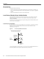
Local Versus Remote Server Authentication
Local Security Database
4-2
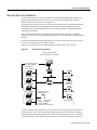
Remote Security Database
4-3
4-2
Configuring Authentication
4-4
Securing Access to Privileged EXEC and Configuration Mode
4-4
Communicating Between the Access Server and the Security Server
4-6
Communicating with a TACACS+ Server 4-7
Communicating with a RADIUS Server 4-8
Configuring Authentication on a TACACS+ Server 4-9
Enabling AAA Globally on the Access Server
4-9
Defining Authentication Method Lists
4-10
Authentication Method List Examples 4-14
Applying Authentication Method Lists
4-15
Configuring Authorization 4-17
Configuring Authorization on the Access Server 4-17
Specifying the Authorization Method 4-18
Specifying Authorization Parameters on a TACACS+ Server
Authorization Examples
4-18
Security Examples
4-19
Simple Local Security Example 4-19
TACACS+ Security Example for Login, PPP, and ARA
4-18
4-19
Contents vii
Appendix A
Managing Modems
A-1
Monitoring Modems A-2
Configuring Microcom Modems for Monitoring A-2
Configuring MICA Modems for Monitoring A-3
Modem Performance Statistics Commands A-4
Managing Modems A-5
Check Modem Type A-5
Set Modem Event Buffer A-5
Remove Inoperable Modems from Service
Polling Modems A-6
Set Polling Attempts A-6
Set Time Interval between Polls
Poll for Modem Statistics A-6
A-6
A-6
Troubleshooting Modems A-7
Perform a Modem Startup Test A-7
Test Two Modems Back-to-Back A-7
Hold and Reset a Modem A-8
Disable a Modem from Dial-Up Services
Debug a Modem A-8
A-8
Upgrading Modem Code A-9
How to Obtain Modem Code A-9
Important Modem Upgrade Commands A-10
Choosing an Update Strategy A-10
Modem Code Scenarios A-11
Displaying Modem Code Versions A-13
Upgrading Modem Code from the Cisco CCO TFTP Server A-14
Download Modem Code from the Cisco CCO TFTP Server to a Local TFTP Server
Copy the Modem Code File from Local TFTP Server to Modems A-18
Upgrading Modem Code from Diskettes A-21
Copy the Modem Code to Your PC Hard Disk A-21
Copy the Modem Code from Your PC to the Modems A-21
Using the Modem Code Bundled with Cisco IOS Software A-25
Appendix B
ROM Monitor
B-1
Entering the ROM Monitor Program
ROM Monitor Command Conventions
Command Aliasing
B-1
B-2
ROM Monitor Commands
Appendix C
B-1
B-2
Using Setup on Cisco IOS Releases 11.2 or 11.3(2)T
Getting Started
C-1
C-1
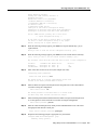
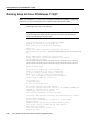
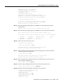
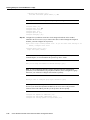
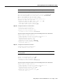
Running Setup for Cisco IOS Release 11.2
C-2
Running Setup for Cisco IOS Release 11.3(2)T C-10
Continuing the Setup Script for T1/PRI Cards C-14
Continuing the Setup Script for E1/PRI Cards C-17
Where to Go Next
viii
Book Title
C-23
A-14
Appendix D
Upgrade VoIP Software
D-1
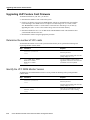
Upgrading VoIP Feature Card Firmware D-2
Determine the number of VFC cards D-2
Identify the VFC ROM Monitor Version D-2
Identify the VFC/ROM Monitor Mode D-3
Download Software in VCWare Mode D-3
Download Software in ROM Monitor Mode D-5
New Hardware Features
D-7
Index
Index
Contents ix
x
Book Title
Preface
This chapter discusses the revisions made to this publication, describes how to get the latest version
of this publication, the conventions used in this guide, and related documentation.
Cisco documentation and additional literature are available on a CD-ROM, which ships with your
product. The Documentation CD-ROM, a member of the Cisco Connection Family, is updated
monthly; therefore, it might be more up to date than printed documentation. To order additional
copies of the Documentation CD-ROM, contact your local sales representative or call customer
service. The CD-ROM is available as a single item or as an annual subscription. You can also access
Cisco documentation on the World Wide Web at http://www.cisco.com,
http://www-china.cisco.com, or http://www-europe.cisco.com.
If you are reading Cisco product documentation on the World Wide Web, you can submit comments
electronically. Click Feedback on the toolbar and select Documentation. After you complete the
form, click Submit to send it to Cisco. We appreciate your comments.
Document Objectives
This configuration guide explains the initial and basic software configuration procedures for the
Cisco AS5300 Universal Access Server. The guide contains procedures for running the setup script
for various Cisco IOS software versions, manually configuring the access server, setting up basic
security, managing modems, and how to use the ROM monitor.
After completing the basic configuration procedures covered in this guide, you can then use the
appropriate companion publications to more completely configure your system. For information on
other publications available, see the section “Related Documentation.”
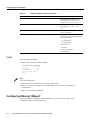
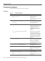
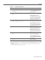
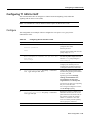
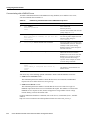
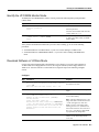
Changes to This Guide
New/Changed Feature
Description
Setup script for Cisco IOS Release 12.02(XD)
The setup script has been updated to reflect the changes
for the Cisco IOS Release 12.02(XD).
Serial interfaces for WAN support
Procedures include how to enable the serial interface,
specify IP routing, and set up external clock timing on a
DCE or DTE interface.
BERT
Briefly describes the Bit Error Rate Tester (BERT)
feature used to test T1 or E1 links.
Preface ix
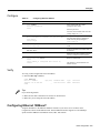
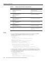
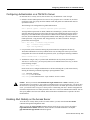
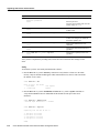
Document Organization
New/Changed Feature
Description
ISDN PRI
Provides an updated list of the switches and also two new
commands used to monitor Non-Facility Associated
Signaling (NFAS) groups and ISDN service and
channels.
Resource pooling and session counting
Describes how to construct unique customer profiles,
groups of DNIS numbers, and tabulate the number of
active connections, calls accepted, calls rejected for each
customer profile, and system resources over specific
time.
T1 CAS and E1 R2 signaling.
Describes how to configure T1 CAS and E1 R2 signaling
with Voice over IP (VoIP).
COT
Describes how use to use Continuity Test (COT) required
by the SS7 network to conduct loopback and tone check
testing on the path before a circuit is established. It is
required for North American SS7 compliance.
RLM
Describes how to use Redundant Link Manager (RLM),
which provides a virtual link management over multiple
IP networks so that the Q.931 signaling protocol and
other proprietary protocols can be transported on top of
multiple redundant links between the Cisco signaling
controller and the access server.
Document Organization
This configuration guide is organized into the following chapters and appendixes:
•
Chapter 1, “First-Time Configuration,” describes how to run the setup script to do a basic
configuration.
•
Chapter 2, “Using Cisco IOS Software,” is a brief overview of how to use the command-line
interface (CLI) to configure the access server.
•
Chapter 3, “Basic Configuration,” provides instructions for configuring the various features of
the access server using the CLI.
•
Chapter 4, “Access Service Security,” describes the basic access server authentication,
authorization, and accounting (AAA) security facility.
•
Appendix A, “Managing Modems,” describes how to manage your modems using monitoring,
polling, and troubleshooting commands.
•
Appendix B, “ROM Monitor,” describes how to use the Cisco AS5300 ROM monitor to isolate
or rule out hardware problems encountered when installing your access server.
•
Appendix C, “Using Setup on Cisco IOS Releases 11.2 or 11.3(2)T,” describes the setup script
for Cisco IOS releases 11.2 and 11.3(2)T.
Where to Get the Latest Version of This Guide
The hard copy of this guide is updated at major releases only and does not always contain the latest
material for enhancements occurring between major releases. You are shipped separate release notes
or configuration notes for spares, hardware, and software enhancements occurring between major
releases.
x
Cisco AS5300 Universal Access Server Software Configuration Guide
Conventions
The online copy of this guide is always up-to-date and integrates the latest enhancements to the
product. You can access the current online copy of this guide on the World Wide Web at
http://www.cisco.com, http://www-china.cisco.com, or http://www-europe.cisco.com.
Conventions
This publication uses the following conventions:
•
The symbol ^ represents the key labeled Control. For example, the key combination ^z means
hold down the Control key while you press the z key.
Command descriptions use these conventions:
•
Examples that contain system prompts denote interactive sessions, indicating the commands that
you should enter at the prompt. The system prompt indicates the current level of the EXEC
command interpreter. For example, the prompt router> indicates that you should be at the user
level, and the prompt router# indicates that you should be at the privileged level. Access to the
privileged level usually requires a password.
•
•
•
•
Commands and keywords are in boldface font.
Arguments for which you supply values are in italic font.
Elements in square brackets ([ ]) are optional.
Alternative but required keywords are grouped in braces ({ }) and separated by vertical bars (|).
Examples use these conventions:
•
•
•
•
•
Terminal sessions and sample console screen displays are in screen font.
Information you enter is in boldface
screen
font.
Nonprinting characters, such as passwords, are in angle brackets (< >).
Default responses to system prompts are in square brackets ([ ]).
Exclamation points (!) at the beginning of a line indicate a comment line.
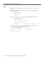
Caution Means reader be careful. You are capable of doing something that might result in
equipment damage or loss of data.
Note Means reader take note. Notes contain helpful suggestions or references to materials not
contained in this manual.
Timesaver Means the described action saves time. You can save time by performing the action
12
9
3
described in the paragraph.
6
Tips Means the following information might help you solve a problem.
Warning This warning symbol means danger. You are in a situation that could cause bodily injury.
Before you work on any equipment, be aware of the hazards involved with electrical circuitry and
be familiar with standard practices for preventing accidents. To see translations of the warnings that
appear in this publication, refer to the Regulatory Compliance and Safety Information document that
accompanied this device.
Preface xi
Conventions
Waarschuwing Dit waarschuwingssymbool betekent gevaar. U verkeert in een situatie die
lichamelijk letsel kan veroorzaken. Voordat u aan enige apparatuur gaat werken, dient u zich bewust
te zijn van de bij elektrische schakelingen betrokken risico's en dient u op de hoogte te zijn van
standaard maatregelen om ongelukken te voorkomen. Voor vertalingen van de waarschuwingen die
in deze publicatie verschijnen, kunt u het document Regulatory Compliance and Safety Information
(Informatie over naleving van veiligheids- en andere voorschriften) raadplegen dat bij dit toestel is
ingesloten.
Varoitus Tämä varoitusmerkki merkitsee vaaraa. Olet tilanteessa, joka voi johtaa
ruumiinvammaan. Ennen kuin työskentelet minkään laitteiston parissa, ota selvää
sähkökytkentöihin liittyvistä vaaroista ja tavanomaisista onnettomuuksien ehkäisykeinoista. Tässä
julkaisussa esiintyvien varoitusten käännökset löydät laitteen mukana olevasta Regulatory
Compliance and Safety Information -kirjasesta (määräysten noudattaminen ja tietoa
turvallisuudesta).
Attention Ce symbole d'avertissement indique un danger. Vous vous trouvez dans une situation
pouvant causer des blessures ou des dommages corporels. Avant de travailler sur un équipement,
soyez conscient des dangers posés par les circuits électriques et familiarisez-vous avec les
procédures couramment utilisées pour éviter les accidents. Pour prendre connaissance des
traductions d’avertissements figurant dans cette publication, consultez le document Regulatory
Compliance and Safety Information (Conformité aux règlements et consignes de sécurité) qui
accompagne cet appareil.
Warnung Dieses Warnsymbol bedeutet Gefahr. Sie befinden sich in einer Situation, die zu einer
Körperverletzung führen könnte. Bevor Sie mit der Arbeit an irgendeinem Gerät beginnen, seien Sie
sich der mit elektrischen Stromkreisen verbundenen Gefahren und der Standardpraktiken zur
Vermeidung von Unfällen bewußt. Übersetzungen der in dieser Veröffentlichung enthaltenen
Warnhinweise finden Sie im Dokument Regulatory Compliance and Safety Information
(Informationen zu behördlichen Vorschriften und Sicherheit), das zusammen mit diesem Gerät
geliefert wurde.
Avvertenza Questo simbolo di avvertenza indica un pericolo. La situazione potrebbe causare
infortuni alle persone. Prima di lavorare su qualsiasi apparecchiatura, occorre conoscere i pericoli
relativi ai circuiti elettrici ed essere al corrente delle pratiche standard per la prevenzione di incidenti.
La traduzione delle avvertenze riportate in questa pubblicazione si trova nel documento Regulatory
Compliance and Safety Information (Conformità alle norme e informazioni sulla sicurezza) che
accompagna questo dispositivo.
Advarsel Dette varselsymbolet betyr fare. Du befinner deg i en situasjon som kan føre til
personskade. Før du utfører arbeid på utstyr, må du vare oppmerksom på de faremomentene som
elektriske kretser innebærer, samt gjøre deg kjent med vanlig praksis når det gjelder å unngå ulykker.
Hvis du vil se oversettelser av de advarslene som finnes i denne publikasjonen, kan du se i
dokumentet Regulatory Compliance and Safety Information (Overholdelse av forskrifter og
sikkerhetsinformasjon) som ble levert med denne enheten.
Aviso Este símbolo de aviso indica perigo. Encontra-se numa situação que lhe poderá causar danos
físicos. Antes de começar a trabalhar com qualquer equipamento, familiarize-se com os perigos
relacionados com circuitos eléctricos, e com quaisquer práticas comuns que possam prevenir
possíveis acidentes. Para ver as traduções dos avisos que constam desta publicação, consulte o
documento Regulatory Compliance and Safety Information (Informação de Segurança e
Disposições Reguladoras) que acompanha este dispositivo.
¡Advertencia! Este símbolo de aviso significa peligro. Existe riesgo para su integridad física. Antes
de manipular cualquier equipo, considerar los riesgos que entraña la corriente eléctrica y
familiarizarse con los procedimientos estándar de prevención de accidentes. Para ver una traducción
xii
Cisco AS5300 Universal Access Server Software Configuration Guide
Related Documentation
de las advertencias que aparecen en esta publicación, consultar el documento titulado Regulatory
Compliance and Safety Information (Información sobre seguridad y conformidad con las
disposiciones reglamentarias) que se acompaña con este dispositivo.
Varning! Denna varningssymbol signalerar fara. Du befinner dig i en situation som kan leda till
personskada. Innan du utför arbete på någon utrustning måste du vara medveten om farorna med
elkretsar och känna till vanligt förfarande för att förebygga skador. Se förklaringar av de varningar
som förkommer i denna publikation i dokumentet Regulatory Compliance and Safety Information
(Efterrättelse av föreskrifter och säkerhetsinformation), vilket medföljer denna anordning.
Related Documentation
Refer to the following publications for additional information, available online:
•
•
•
•
•
•
•
•
Cisco AS5300 Universal Access Server Chassis Installation Guide
Cisco AS5300 Universal Access Server Module Installation Guide
Voice Over IP for Cisco AS5300 Software Configuration Guide
System Error Messages and Debug Command Reference publications
Dial Solutions Configuration Guide
Dial Case Study
Cisco SS7/CCS7 Dial Access Solution System Integration
Cisco IOS software configuration guide, feature modules, and command reference publications
These publications are available on the documentation CD that came with your access server, on the
World Wide Web from Cisco’s home page, or in orderable printed format.
Cisco Connection Online
Cisco Connection Online (CCO) is Cisco Systems’ primary, real-time support channel. Maintenance
customers and partners can self-register on CCO to obtain additional information and services.
Available 24 hours a day, 7 days a week, CCO provides a wealth of standard and value-added
services to Cisco’s customers and business partners. CCO services include product information,
product documentation, software updates, release notes, technical tips, the Bug Navigator,
configuration notes, brochures, descriptions of service offerings, and download access to public and
authorized files.
CCO serves a wide variety of users through two interfaces that are updated and enhanced
simultaneously: a character-based version and a multimedia version that resides on the World Wide
Web (WWW). The character-based CCO supports Zmodem, Kermit, Xmodem, FTP, and Internet
e-mail, and it is excellent for quick access to information over lower bandwidths. The WWW version
of CCO provides richly formatted documents with photographs, figures, graphics, and video, as well
as hyperlinks to related information.
You can access CCO in the following ways:
•
•
•
•
Online at http://www.cisco.com
Online at http://www-europe.cisco.com
Online at http://www-china.cisco.com
Telnet to cco.cisco.com
Preface xiii
Cisco Connection Online
•
Modem: From North America, 408 526-8070; from Europe, 33 1 64 46 40 82. Use the
following terminal settings: VT100 emulation; databits: 8; parity: none; stop bits: 1; and
connection rates up to 28.8 kbps.
For a copy of CCO’s Frequently Asked Questions (FAQ), contact [email protected]. For
additional information, contact [email protected].
Note If you are a network administrator and need personal technical assistance with a Cisco
product that is under warranty or covered by a maintenance contract, contact Cisco’s Technical
Assistance Center (TAC) at 800 553-2447, 408 526-7209, or [email protected]. To obtain general
information about Cisco Systems, Cisco products, or upgrades, contact 800 553-6387,
408 526-7208, or [email protected].
xiv
Cisco AS5300 Universal Access Server Software Configuration Guide
CHAPTER
1
First-Time Configuration
This chapter describes how to power ON the Cisco AS5300 universal access server and configure it
using the prompt-driven setup script (also called the System Configuration dialog). The following
sections are included:
•
•
Using the Setup Script
Where to Go Next
If you prefer to configure the access server manually, proceed to the next chapter “Using Cisco IOS
Software” to familiarize yourself with the command-line interface (CLI) and then proceed to the
following chapter “Basic Configuration” for step-by-step instructions.
Using the Setup Script
The setup script in this section uses the latest release version of Cisco IOS software.
Note If your system is running Cisco IOS Release 11.2 or 11.3(2)T, see the appendix “Using Setup
on Cisco IOS Releases 11.2 or 11.3(2)T” for intructions and screen displays.
Getting Started
Before you power on the access server and begin to use the setup script in the System Configuration
dialog, make sure you have already connected the cables to the access server and configured your
PC terminal emulation program for 9600 baud, 8 data bits, no parity, and 2 stop bits. All
configuration will be performed from your PC terminal emulation program window.
The prompts and resulting messages vary depending on your responses. For most configurations,
you can press Enter to accept the default entries displayed in square ([]) brackets.
Note Information that you enter is in this boldface font. Also note that if you make a mistake
during the configuration, exit and run the System Configuration dialog again by pressing Ctrl-c, and
then type setup at the enable prompt (5300#).
First-Time Configuration 1-1
Using the Setup Script
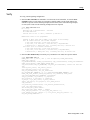
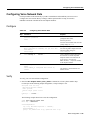
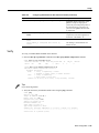
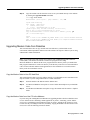
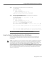
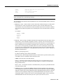
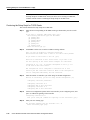
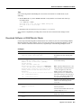
To use the setup script take the following steps:
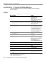
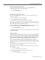
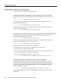
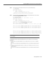
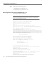
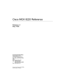
Step 1
Power Switch Location
H10690
Figure 1-1
Power ON the access server. The power switch is on the rear panel, at the upper right
corner near the power cord, as shown in Figure 1-1.
Universal access
server
Power
switch
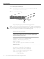
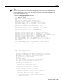
Messages will begin to appear in your terminal emulation program window.
Do not press any keys on the keyboard until the messages stop. Any keys pressed during this time
will be interpreted as the first command typed when the messages stop, which might cause you to power cycle
the access server and start over. It will take a few minutes for the messages to stop.
Caution
The messages look similar to the following:
Note The displayed messages depend on the Cisco IOS software release and feature set
you selected. The screen displays in this section are for reference only and might not
exactly reflect the messages on your console.
System Bootstrap, Version 12.0(3)T, RELEASED SOFTWARE
Copyright (c) 1994-1998 by cisco Systems, Inc.
AS5300 processor with 32768 Kbytes of main memory
rommon 3 > b flash:2:
program load complete, entry point: 0x80008000, size: 0x5d7b5c
Self decompressing the image :
#################################################################################
###################]
Restricted Rights Legend
Use, duplication, or disclosure by the Government is
subject to restrictions as set forth in subparagraph
(c) of the Commercial Computer Software - Restricted
Rights clause at FAR sec. 52.227-19 and subparagraph
(c) (1) (ii) of the Rights in Technical Data and Computer
Software clause at DFARS sec. 252.227-7013.
cisco Systems, Inc.
170 West Tasman Drive
1-2
Cisco AS5300 Universal Access Server Software Configuration Guide
Getting Started
San Jose, California 95134-1706
Cisco Internetwork Operating System Software
IOS (tm) 5300 Software (C5300-JS-M), Released Version 12.0(19981001:221340)
[ayeh-wk_0_6_0 100]
Copyright (c) 1986-1998 by cisco Systems, Inc.
Compiled Thu 01-Oct-98 15:13 by ayeh
Image text-base: 0x600088E8, data-base: 0x609F6000
cisco AS5300 (R4K) processor (revision A.14) with 32768K/16384K bytes of memory.
Processor board ID 05433592
R4700 processor, Implementation 33, Revision 1.0 (512KB Level 2 Cache)
Bridging software.
X.25 software, Version 3.0.0.
SuperLAT software copyright 1990 by Meridian Technology Corp).
TN3270 Emulation software.
Primary Rate ISDN software, Version 1.1.
Backplane revision 2
Manufacture Cookie Info:
EEPROM Type 0x0001, EEPROM Version 0x01, Board ID 0x30,
Board Hardware Version 1.0, Item Number 73-2414-2,
Board Revision 3, Serial Number 05433592,
PLD/ISP Version 255.255, Invalid Date code.
1 Ethernet/IEEE 802.3 interface(s)
1 FastEthernet/IEEE 802.3 interface(s)
4 Serial network interface(s)
120 terminal line(s)
4 Channelized T1/PRI port(s)
128K bytes of non-volatile configuration memory.
8192K bytes of processor board System flash partition 1 (Read/Write)
8192K bytes of processor board System flash partition 2 (Read/Write)
4096K bytes of processor board Boot flash (Read/Write)
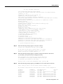
--- System Configuration Dialog ---
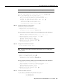
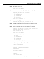
Step 2
When the following message appears, enter yes to continue:
Continue with configuration dialog? [yes/no]: yes
At any point you may enter a question mark '?' for help.
Use ctrl-c to abort configuration dialog at any prompt.
Default settings are in square brackets '[]'.
Step 3
When the following message appears, enter No to configure all interfaces. Note that if
you enter Yes, your system will not be configured correctly:
Basic management setup configures only enough connectivity
for management of the system, extended setup will ask you
to configure each interface on the system
Would you like to enter basic management setup? [yes/no]: no
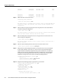
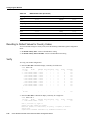
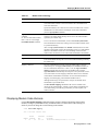
Step 4
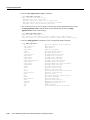
When the following message appears, press Enter to see the current interface summary:
First, would you like to see the current interface summary? [yes]:
Any interface listed with OK? value "NO" does not have a valid configuration
Interface
Ethernet0
FastEthernet0
Group-Async1
Serial0
Serial1
Serial2
Serial3
IP-Address
171.69.90.18
unassigned
171.69.90.18
unassigned
unassigned
unassigned
unassigned
OK?
YES
YES
YES
YES
YES
YES
YES
Method
NVRAM
unset
unset
unset
unset
unset
unset
Status
up
administratively
down
administratively
administratively
administratively
administratively
down
down
down
down
down
Protocol
down
down
down
down
down
down
down
First-Time Configuration 1-3
Using the Setup Script
Serial0:0
Serial0:1
.
.
.
Serial3:21
Serial3:22
Serial3:23
Step 5
unassigned
unassigned
YES unset
YES unset
down
down
down
down
unassigned
unassigned
171.69.90.18
YES unset
YES unset
YES unset
down
down
down
down
down
down
Enter a host name for the access server:
Configuring global parameters:
Enter host name [Router]: 5300
The enable secret is a password used to protect access to privileged EXEC and
configuration modes. This password, after entered, becomes encrypted in the
configuration.
Step 6
Enter an enable secret password. This password is encrypted (more secure) and cannot be
seen when viewing the configuration:
Enter enable secret: lab
The enable password is used when you do not specify an enable secret password,
with some older software versions, and some boot images.
Step 7
Enter an enable password. This password is not encrypted (less secure) and can be seen
when viewing the configuration:
Enter enable password: guessme
The virtual terminal password is used to protect access to the router over a
network interface.
Step 8
Enter the virtual terminal password, which is used for remote console access:
Enter virtual terminal password: guessagain
Step 9
Enter yes to the system management prompt if you want the access server to be managed
by the system controller. If you enter yes, you need to also enter the shelf ID and the
system controller’s IP addresss and password. The system controller uses the shelf-id to
identify an access server or dial shelf. The shelf ID is a number from 1 to 999 and must
be unique in the POP management domain. The system controller password is used to
authenticate messages between the system controller and managed shelves.
Configure System Management? [yes/no]: yes
Shelf-id [0]:
System Controller IP address: 172.87.98.01
System Controller password: sctest
Step 10
Respond to the following prompts as appropriate for your network:
Configure SNMP Network Management? [no]: yes
Community string [public]:
Configure LAT? [yes]:
Configure AppleTalk? [no]: yes
Multizone networks? [no]: yes
Configure DECnet? [no]:
Configure IP? [no]:
Configure IGRP routing? [yes]:
Your IGRP autonomous system number [1]: 15
1-4
Cisco AS5300 Universal Access Server Software Configuration Guide
Getting Started
Note If you answer no to IGRP, you will be prompted to configure RIP.
Configure
Configure
Configure
Configure
Configure
Step 11
CLNS? [no]:
IPX? [no]: yes
Vines? [no]:
XNS? [no]:
Apollo? [no]:
Configure the asynchronous serial lines for the integrated modems on the modules
installed in the access server. (If you want to allow users to dial in through the integrated
modems, you must configure the async lines.)
Async lines accept incoming modems calls. If you will have users dialing in via
modems, configure these lines.
Configure Async lines? [yes]:
Note We recommend that you do not change the async line speed for modems.
However, for V.110 terminal adapters, we recommend that the speed not go above 19200.
Async line speed [115200]:
Will you be using the modems for inbound dialing? [yes]:
Note If your asynchronous interfaces will be using the same basic configuration
parameters, we recommend that you group them so that they can be configured as a
group. Otherwise, you will need to configure each interface separately.
Would you like to put all async interfaces in a group and configure them all at
one time ? [yes]
Note Dynamic IP addresses permit dial-in users to choose a static IP address when they
dial in. If you do not allow dynamic IP addresses, the access server will provide IP
addresses from an IP address pool that you set up later in the next prompt.
Allow dial-in users to choose a static IP address? [no]:
Configure for TCP header compression? [yes]:
Configure for routing updates on async links? [no]:
Note Make sure the starting and ending addresses of the IP pool are in the same subnet.
Enter the starting address of IP local pool? [X.X.X.X]: 172.20.30.40
Enter the ending address of IP local pool? [X.X.X.X]: 172.20.30.88
You can configure a test user to verify that your dial-up service is working
properly.
First-Time Configuration 1-5
Using the Setup Script
What is the username of the test user? [user]:
What is the password of the test user? [passwd]:
Will you be using the modems for outbound dialing? [no]:
Configure for Async IPX? [yes]: no
Configure for Appletalk Remote Access (ARA)? [no]: yes
AppleTalk Network for ARAP clients [1]:
Zone name for ARAP clients [ARA Dialins]:
Allow ARAP "Guest" logins? [yes/no]: yes
Step 12
Enter the letter corresponding to the ISDN switch type that matches your telco switch
type or press Enter to accept the default:
Do you want to configure ISDN switch type? [yes]:
The following ISDN switch types are available:
[a] primary-4ess
[b] primary-5ess
[c] primary-dms100
[d] primary-net5
[e] primary-ntt
[f] primary-ts014
Enter the switch type [b]:
Step 13
Press Enter to allow users to dial in via ISDN or analog modems:
Next, you will be prompted to configure controllers.
These controllers enable users to dial in via ISDN or analog modems.
Do you intend to allow users to dial in? [yes]:
There are 8 controllers on this access server. If you want to use
the full capacity of the access server configure all controllers.
Controller T1 0,1,..etc in software corresponds to Port 0,1,..etc
on the back of the access server.
PRI configuration can be configured to controllers all at once
based on your PRI controllers selection. Where as CAS configuration
will be configured individually for each controller.
Step 14
Enter the number of controllers you will be using for the PRI configuration or press Enter
to configure all controllers:
Enter # of controllers, you will be using for PRI configuration [8]:
Configuring controller parameters:
Step 15
Set the CAS configuration options for the first controller you are configuring. First, press
Enter to set robbed-bit signaling on the controller:
Configuring controller T1 2:
Will you be using CT1 (robbed bit signaling) on this controller? [yes]:
Step 16
Enter your telco framing type:
The following framing types are available: esf | sf
Enter the framing type [esf]:
Step 17
Enter your telco line code type:
The following linecode types are available: ami | b8zs
Enter the line code type [b8zs]:
1-6
Cisco AS5300 Universal Access Server Software Configuration Guide
Getting Started
Step 18
Enter the letter corresponding to the signaling type to support modem pooling over the
T1 lines or press Enter to accept the default:
The following line signaling types are available:
[a] e&m-fgb
[b] e&m-fgd
[c] e&m-immediate-start
[d] fxs-ground-start
[e] fxs-loop-start
[f] sas-ground-start
[g] sas-loop-start
Enter the line signaling type [a]:
Step 19
Enter the tone signaling type:
The following tone signaling types are available: dtmf | mf
Enter the tone signal type [dtmf]:
Step 20
Press Enter to configure digital number identification service (DNIS) over T1 lines:
Do you want to provision DNIS address information? [yes]:
Step 21
Repeat Step 15 to Step 20 to configure the remaining controllers.
Step 22
Enter yes to configure the Ethernet 0 interface (this is the Ethernet 10BaseT port) if you
plan to use this interface to manage and monitor the access server:
Configuring interface parameters:
Do you want to configure Ethernet0 interface? [no]: yes
Configure IP on this interface? [no]: yes
IP address for this interface: 172.21.40.10
Subnet mask for this interface [255.0.0.0] :
Class B network is 172.21.0.0, 16 subnet bits; mask is /16
Configure LAT on this interface? [no]:
Configure AppleTalk on this interface? [no]:
Configure IPX on this interface? [no]:
Step 23
Press Enter or enter yes to configure the Fast Ethernet 0 interface (this is the Ethernet
100BaseT port) to connect the access server to a LAN:
Do you want to configure FastEthernet0 interface? [yes]: yes
Note Full duplex mode enables simultaneous data transfer between a sending and a
receiving station.
Operate in full-duplex mode? [no]: yes
Operate at 100 Mbps speed? [yes]:
Configure IP on this interface? [yes]:
IP address for this interface [X.X.X.X]: 172.22.50.10
Subnet mask for this interface [255.255.0.0] :
Class B network is 172.22.0.0, 16 subnet bits; mask is /16
Configure LAT on this interface? [no]:
Configure AppleTalk on this interface? [no]:
Configure IPX on this interface? [no]:
First-Time Configuration 1-7
Using the Setup Script
Step 24
Configure your serial intefaces by responding to the following prompts:
Do you want to configure Serial0
interface? [no]: yes
Note If using the serial interfaces to route data from the T1/PRI or E1/PRI ports to a
WAN, you need to configure IP on the interface. Enter the IP address of the WAN device
to which the data will be routed.
Configure IP on this interface? [no]: yes
Configure IP unnumbered on this interface? [no]:
IP address for this interface: 173.20.30.40
Subnet mask for this interface [255.255.0.0] :
Class B network is 173.20.0.0, 16 subnet bits; mask is /16
Configure LAT on this interface? [no]:
Configure AppleTalk on this interface? [no]:
Configure IPX on this interface? [no]:
Step 25
Repeat Step 24 to configure the other three serial interfaces, if necessary.
Step 26
Configure the PRI D-channel (signaling channel):
Do you want to configure Serial0:23 (PRI D-channel) interface? [no]: yes
Configure IP on this interface? [no]: yes
Configure IP unnumbered on this interface? [no]:
IP address for this interface: 173.20.30.40
Subnet mask for this interface [255.255.0.0] :
Class B network is 173.20.0.0, 16 subnet bits; mask is /16
Configure LAT on this interface? [no]:
Configure AppleTalk on this interface? [no]:
Configure IPX on this interface? [no]:
Step 27
Repeat Step 26 for each D-channel.
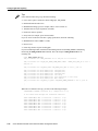
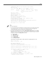
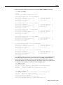
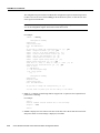
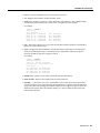
After you complete the configuration script, messages similar to the following appear.
The following configuration command script was created:
hostname 5300
enable secret 5 $1$WVLB$YD0zbQsu3nqZh/bnN2fwX0
enable password guessme
line vty 0 4
password guessagain
syscon shelf-id 0
syscon address 172.87.98.1 sctest
snmp-server community public
!
appletalk routing
no decnet routing
no ip routing
no clns routing
ipx routing
no vines routing
no xns routing
no apollo routing
!
line 1 120
speed 115200
flowcontrol hardware
login local
autoselect during-login
autoselect ppp
1-8
Cisco AS5300 Universal Access Server Software Configuration Guide
Getting Started
modem dialin
ip local pool setup_pool 172.20.30.40 172.20.30.88
!
username user password passwd
!
arap network 1 ARA Dialins
line 1 120
arap enable
autoselect arap
!
! Turn off IPX to prevent network conflicts.
interface Ethernet0
no ipx network
interface FastEthernet0
no ipx network
interface Serial0
no ipx network
interface Serial1
no ipx network
interface Serial2
no ipx network
interface Serial3
no ipx network
interface Serial0:23
no ipx network
interface Serial1:23
no ipx network
interface Serial2:23
no ipx network
interface Serial3:23
no ipx network
!
isdn switch-type primary-5ess
!
controller T1 0
no shutdown
framing esf
linecode b8zs
cas-group 0 timeslots 1-24 type e&m-fgb dtmf dnis
!
controller T1 1
no shutdown
framing esf
linecode b8zs
cas-group 0 timeslots 1-24 type e&m-fgb dtmf dnis
!
controller T1 2
no shutdown
framing esf
linecode b8zs
cas-group 0 timeslots 1-24 type e&m-fgb dtmf dnis
!
controller T1 3
no shutdown
framing esf
linecode b8zs
cas-group 0 timeslots 1-24 type e&m-fgb dtmf dnis
!
controller T1 4
no shutdown
framing esf
linecode b8zs
cas-group 0 timeslots 1-24 type e&m-fgb dtmf dnis
!
controller T1 5
First-Time Configuration 1-9
Using the Setup Script
no shutdown
framing esf
linecode b8zs
cas-group 0 timeslots 1-24 type e&m-fgb dtmf dnis
!
controller T1 6
no shutdown
framing esf
linecode b8zs
cas-group 0 timeslots 1-24 type e&m-fgb dtmf dnis
!
controller T1 7
no shutdown
framing esf
linecode b8zs
cas-group 0 timeslots 1-24 type e&m-fgb dtmf dnis
scheduler interval 1000
line console 0
logging synchronous
!
interface Ethernet0
no shutdown
ip address 172.21.40.10 255.255.0.0
no lat enabled
no mop enabled
!
interface FastEthernet0
duplex full
speed 100
ip address 172.22.50.10 255.255.0.0
no lat enabled
no mop enabled
!
interface Serial0
no shutdown
ip address 173.20.30.40 255.255.0.0
no lat enabled
no mop enabled
!
interface Serial1
shutdown
no ip address
!
interface Serial2
shutdown
no ip address
!
interface Serial3
shutdown
no ip address
!
interface Serial0:23
no shutdown
no ip address
no lat enabled
no mop enabled
!
interface Serial1:23
no shutdown
ip address 173.20.30.40 255.255.0.0
no lat enabled
no mop enabled
!
interface Serial2:23
no shutdown
1-10
Cisco AS5300 Universal Access Server Software Configuration Guide
Getting Started
no ip address
no lat enabled
no mop enabled
no shutdown
no ip address
no lat enabled
no mop enabled
!
Interface Group-Async1
group-range 1 120
ip unnumbered FastEthernet0
encapsulation ppp
ppp authentication chap pap
peer default ip address pool setup_pool
ip tcp header-compression passive
async mode interactive
dialer-list 1 protocol ip permit
dialer-list 1 protocol ipx permit
!
end
end
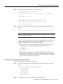
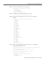
Step 28
Enter 0, 1, or 2 when the following prompt is displayed:
[0] Go to the IOS command prompt without saving this config.
[1] Return back to the setup without saving this config.
[2] Save this configuration to nvram and exit.
Enter your selection [2]:
Use this configuration? [yes/no]: yes
Building configuration...
Use the enabled mode 'configure' command to modify this configuration.
Press RETURN to get started!
%LINK-3-UPDOWN: Interface Ethernet0, changed state to up
%LINK-3-UPDOWN: Interface Serial0, changed state to down
%LINK-3-UPDOWN: Interface Serial1, changed state to down
<Additional messages omitted.>
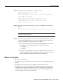
Step 29
When the messages stop displaying on your screen, press Enter to get the following
prompt:
5300>
%AT-6-ONLYROUTER: Ethernet0: AppleTalk port enabled; no neighbors found
Note If you see this message, it means that no other routers were found on the network
attached to the port.
First-Time Configuration 1-11
Where to Go Next
Step 30
The 5300> prompt indicates that you are now at the command-line interface (CLI) and
you have just completed the basic access server configuration. However, this is not a
complete configuration. At this point you have two options:
•
Run the setup script in the System Configuration dialog again and create another
configuration. Enter the following commands to repeat the setup script:
5300> enable
Password: <password>
5300# setup
•
Modify the existing configuration or configure additional features with the CLI as
described in the Dial Solutions Configuration Guide, the Dial Solutions Command
Reference Guide the Cisco IOS software configuration guide, and command reference
publications.
Where to Go Next
At this point you can proceed to:
1-12
•
The next chapter “Using Cisco IOS Software” to learn how to use the CLI to configure additional
features.
•
•
The chapter “Access Service Security” to configure security on the access server.
The chapter “Basic Configuration” for step-by-step instructions to configure the access server
manually. You can also refer to the Cisco IOS software configuration guide and command
reference publications for more advanced configuration topics. These publications are available
on the Documentation CD-ROM that arrived with your access server, on the World Wide Web
from Cisco’s home page, or you can order printed copies. If using Cisco’s home page, refer to
the topic Configuring Selected (feature) Cisco IOS Features, available online at
http://www.cisco.com/univercd/cc/td/doc/product/access/acs_serv/5300/sw_conf/index.htm
Cisco AS5300 Universal Access Server Software Configuration Guide
CHAPTER
2
Using Cisco IOS Software
This chapter describes what you need to know about the Cisco IOS software (the software that runs
the access server) before you configure the access server using the command-line interface (CLI).
This chapter includes:
•
•
•
•
•
•
Getting Help
Understanding Command Modes
How to Find Command Options
Undoing a Command or Feature
Saving Configuration Changes
Where to Go Next
Understanding these concepts will save you time later. If you have never used the Cisco IOS software
or need a refresher, take a few minutes to read this chapter now.
If you are already familiar with the Cisco IOS software, proceed to the next chapter, “Basic
Configuration.”
Getting Help
Use the question mark (?) and arrow keys to help you enter commands:
•
For a list of available commands, enter a question mark:
5300> ?
•
To complete a command, enter a few known characters followed by a question mark (with no
space):
5300> s?
•
For a list of command variables, enter the command followed by a space and a question mark:
5300> show ?
•
To redisplay a command you previously entered, press the up arrow key. You can continue to
press the up arrow key for more commands.
Using Cisco IOS Software 2-1
Understanding Command Modes
Understanding Command Modes
You will need to use many different command modes to use to configure the access server. Each
command mode restricts you to a subset of commands. If you are having trouble entering a
command, check the prompt, and then enter the question mark (?) for a list of available commands.
You might be in the wrong command mode or using the wrong syntax.
In the following example, notice how the prompt changes after each command to indicate a new
command mode:
5300> enable
5300> password
5300# configure terminal
5300(config)# interface ethernet 0
5300(config-if)# line 0
5300(config-line)# controller t1 0
5300(config-controller)# exit
5300(config)# exit
5300#
%SYS-5-CONFIG_I: Configured from console by console
The last message is normal and does not indicate an error. Press Return to get the 5300> prompt.
Note You can press Ctrl-Z at any time to immediately return to enable mode (5300#), instead of
entering exit, which returns you to the previous mode.
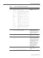
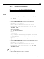
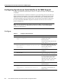
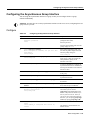
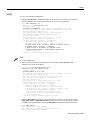
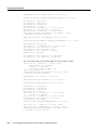
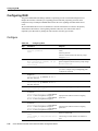
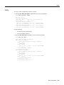
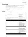
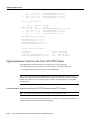
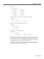
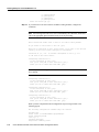
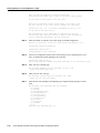
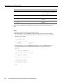
How to Find Command Options
This section explains how to display options for a command. To display options for a command,
enter a ? at the configuration prompt, or after entering part of a command followed by a space. The
configuration parser displays options available with the command. For example, if you were in
global configuration mode, typed the command arap, and wanted to see all the keywords and
arguments for that command, you would type arap ?.
Table 2-1 shows examples of this function.
Table 2-1
How to Find Command Options
Step
Command
Purpose
1
5300> enable
Password: <password>
5300#
Enter enable mode.
Enter the password.
You have entered enable mode
when the prompt changes to 5300#.
2
3
2-2
5300# config terminal
Enter configuration commands, one per line. End
with CNTL/Z.
5300(config)#
Enter global configuration mode
and the prompt changes to
5300(config)# controller t1 ?
<0-3> Controller unit number
5300(config)# controller t1 1
Specify the T1 controller that you
want to configure using the
controller T1 number global
configuration command.
Cisco AS5300 Universal Access Server Software Configuration Guide
5300(config)#.
How to Find Command Options
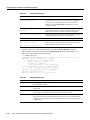
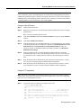
Table 2-1
How to Find Command Options (Continued)
Step
Command
Purpose
4
5300(config-controller)# ?
Controller configuration commands:
cablelength
Specify cable length for a DS1 link
cas-group
Configure the specified timeslots
for CAS(Channel Associate Signals)
channel-group Specify timeslots to channel-group
mapping for an interface
clock
Specify the clock source for a DS1
link
default
Set a command to its defaults
description
Controller specific description
ds0
ds0 commands
exit
Exit from controller configuration
mode
fdl
Specify the FDL standard for a DS1
data link
framing
Specify the type of Framing on a DS1
link
help
Description of the interactive help
system
linecode
Specify line encoding method for
a DS1 link
loopback
Put the entire T1 line into loopback
no
Negate a command or set its defaults
pri-group
Configure specified timeslots for
PRI
shutdown
Shut down a DS1 link (send Blue
Alarm)
Display controller configuration
commands.
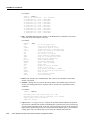
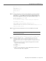
5
5300(config-controller)# cas-group ?
<0-23> Channel number
Display the options for the
cas-group controller configuration
command. This command is used to
configure the channel-associated
signaling on a T1 controller.
6
5300(config-controller)# cas-group 1 ?
timeslots List of timeslots in the cas-group
Display the only command
(timeslots) available in cas-group
1.
7
5300(config-controller)# cas-group 1 timeslots ?
<1-24> List of timeslots which comprise the
cas-group
Display the range for the timeslot
option. Specify a timeslot range of
values from 1 to 24. You can specify
timeslot ranges (for example, 1-24),
individual timeslots separated by
commas (for example 1, 3, 5), or a
combination of the two (for
example 1-3, 8, 17-24). The 16th
timeslot is not specified in the
command line, because it is
reserved for transmitting the
channel signaling.
8
5300(config-controller)# cas-group 1 timeslots 1-24
?
service Specify the type of service
type
Specify the type of signaling
Display the two commands (service
and type) available for the
timeslots.
Using Cisco IOS Software 2-3
Undoing a Command or Feature
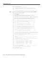
Table 2-1
How to Find Command Options (Continued)
Step
Command
Purpose
9
5300(config-controller)# cas-group 1 timeslots 1-24
type ?
e&m-fgb
E & M Type II FGB
e&m-fgd
E & M Type II FGD
e&m-immediate-start E & M Immediate Start
fxs-ground-start
FXS Ground Start
fxs-loop-start
FXS Loop Start
sas-ground-start
SAS Ground Start
sas-loop-start
SAS Loop Start
List supported signaling types.
10
5300(config-controller)# cas-group 1 timeslots 1-24
type e&m-fgb ?
dtmf
DTMF tone signaling
mf
MF tone signaling
service Specify the type of service
<cr>
Display the types of
channel-associated signaling
available for the e&m-fgb type.
11
5300(config-controller)# cas-group 1 timeslots 1-24
type e&m-fgb dtmf ?
dnis
DNIS addr info provisioned
service
Specify the type of service
<cr>
Display the options supported for
the DTMF tone signaling option.
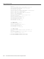
Undoing a Command or Feature
If you want to undo a command you entered or disable a feature, enter the keyword no before most
commands; for example, no ip routing.
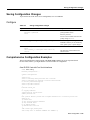
Saving Configuration Changes
Enter the copy running-config startup-config command to save your configuration changes to
nonvolatile random-access memory (NVRAM) so that they will not be lost if there is a system reload
or power outage. For example:
5300# copy running-config startup-config
Building configuration...
It might take a minute or two to save the configuration to NVRAM. After the configuration has been
saved, the following appears:
[OK]
5300#
Where to Go Next
Now that you have learned some Cisco IOS software basics, you can begin to configure the access
server using the CLI.
Remember that:
•
•
2-4
You can use the question mark (?) and arrow keys to help you enter commands.
Each command mode restricts you to a set of commands. If you are having difficulty entering a
command, check the prompt and then enter the question mark (?) for a list of available
commands. You might be in the wrong command mode or using the wrong syntax.
Cisco AS5300 Universal Access Server Software Configuration Guide
Where to Go Next
•
If you want to disable a feature, enter the keyword no before the command; for example, no ip
routing.
•
You need to save your configuration changes to NVRAM so that they will not be lost if there is
a system reload or power outage.
Proceed to the next chapter “Basic Configuration” to begin configuring the access server.
Using Cisco IOS Software 2-5
Where to Go Next
2-6
Cisco AS5300 Universal Access Server Software Configuration Guide
CHAPTER
3
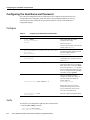
Basic Configuration
This chapter describes how to use the Cisco IOS software command-line interface (CLI) to configure
basic access server functionality, including:
•
LAN and WAN configuration (including Integrated Services Digital Network [ISDN], Primary
Rate Interface [PRI], and channelized T1 and E1)
•
•
Modem configuration
Voice-over IP (VoIP) configuration
Follow the procedures in this chapter to configure the access server manually or if you want to
change the configuration after you have run the setup script (described in the chapter “First-Time
Configuration”).
This chapter does not describe every configuration possible—only a small portion of the most
commonly used configuration procedures. For advanced configuration topics and procedures, refer
to the topic Configuring Cisco IOS Features online at
http://www.cisco.com/univercd/cc/td/doc/product/access/acs_serv/5300/index.htm
You can also view these publications on the Documentation CD-ROM that arrived with your access
server, or you can order printed copies separately.
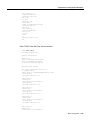
If you are experienced using the Cisco IOS software, you might find the “Comprehensive
Configuration Examples” section at the end of this chapter a useful reference for configuration.
Note If you skipped the previous chapter, “Using Cisco IOS Software,” and you have never
configured a Cisco access server, go back to that chapter and read it now. This chapter provides
important information you will need to succeed with the configuration.
Basic Configuration 3-1
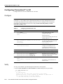
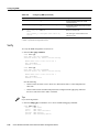
Configuring the Host Name and Password
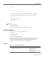
Configuring the Host Name and Password
One of the first configuration tasks you might want to do is configure the host name and set an
encrypted password. Configuring a host name allows you to distinguish multiple Cisco access
servers from each other. Setting an encrypted password allows you to prevent unauthorized
configuration changes.
Configure
Table 3-1
Configuring the Host Name and Passwords
Step
Command
Purpose
1
Router> enable
Password: <password>
Router#
Enter enable mode (also called
privileged EXEC mode).
Enter the password.
You have entered enable mode when the
prompt changes to 5300#.
2
Router# configure terminal
Enter configuration commands, one per line. End
with CNTL/Z.
Router(config)#
Enter global configuration mode. You
have entered global configuration mode
when the prompt changes to
3
Router(config)# hostname 5300
5300(config)#
Change the name of the access server to
a meaningful name. Substitute your host
name for 5300.
4
5300(config)# enable secret guessme
Enter an enable secret password. This
password provides access to privileged
EXEC mode. When a user types enable
at the EXEC prompt (5300> ), they must
enter the enable secret password to gain
access to configuration mode. Substitute
your enable secret for guessme.
5
5300(config)# line con 0
Enter line configuration mode to
configure the console port. When you
enter line configuration mode, the
prompt changes to
5300(config-line)#.
5300(config-line)# exec-timeout 0 0
Router(config)#.
Prevent the access server’s EXEC
facility from timing out if you do not
type any information on the console
screen for an extended period.
5300(config-line)# exit
5300(config)#
Verify
To verify that you configured the right host name and passwords:
•
Enter the show config command:
5300(config)# show config
Using 1888 out of 126968 bytes
3-2
Cisco AS5300 Universal Access Server Software Configuration Guide
Exit back to global configuration mode.
Configuring Alarms
!
version XX.X
.
.
!
hostname 5300
!
enable secret 5 $1$60L4$X2JYOwoDc0.kqa1loO/w8/
.
Check the host name and encrypted password displayed near the top of the command output.
•
Exit global configuration mode and attempt to reenter it using the new enable password:
5300# exit
5300 con0 is now available
Press RETURN to get started.
5300> enable
Password: guessme
5300#
Tips
If you are having trouble:
•
•
Make sure Caps Lock is off.
Make sure you entered the correct passwords. Passwords are case sensitive.
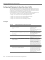
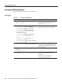
Configuring Alarms
Facility alarm currently monitors the following failure events:
•
•
•
•
Interface down
T1/E1 Controller down
Modem card failure
Redundant Power Supply (RPS) failure
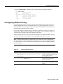
IOS polls every second to detect the failure events that you have configured and will turn ON the
alarm when any one of the failure events is detected. By default, facility alarm in OFF. Users have
to configure one of the following commands to enable monitoring of the failure conditions.
Enter [no] before the full command to disable any of the alarm commands.
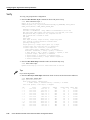
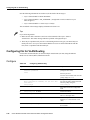
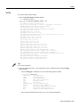
Configure
Table 3-2
Configuring Ethernet 10BaseT
Step
Command
Purpose
1
5300> enable
Password: <password>
5300#
Enter enable mode (also called
privileged EXEC mode).
Enter the password.
You have entered enable mode when the
prompt changes to 5300#.
Basic Configuration 3-3
Configuring Ethernet 10BaseT
Table 3-2
Configuring Ethernet 10BaseT (Continued)
Step
Command
Purpose
2
5300# facility-alarm detect interface ethernet 0
Turn ON alarm when interface goes
down (interfaces are "ethernet 0" or
"fastethernet 0" or "serial <0-3>").
3
5300# facility-alarm detect controller t1 0
Turn ON alarm when controller goes
down (values are "t1 <0-7>" or "e1
<0-7>" ).
4
5300# facility-alarm detect modem-board 1
Turn ON alarm when modem board
present in slot# fails.
5
5300# facility-alarm detect rps
Turn ON alarm when RPS failure event
is detected, any of the following failures
will turn ON the alarm.
• i/p voltage failure
• o/p voltage failure
• thermal failure
• fan failure
• overvoltage condition
• multiple failures
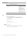
Verify
To see the status of the alarms:
•
Enter the show
facility-alarm
command:
5300# show facility-alarm
Device
State
Ethernet0
UP
FastEthernet0
OWN
Facility Alarm is ON
5300#
Tips
If you are having trouble:
•
•
Make sure the cable connections are not loose or disconnected.
•
Make sure your alarm is operational.
Make sure you are using Number 12 or 14 AWG copper wires to connect to the alarm port
terminal blocks.
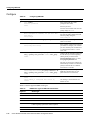
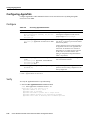
Configuring Ethernet 10BaseT
Assign an IP address to the Ethernet 10BaseT interface of your access server so that it can be
recognized as a device on the Ethernet LAN.
3-4
Cisco AS5300 Universal Access Server Software Configuration Guide
Configure
Configure
Table 3-3
Configuring Ethernet 10BaseT
Step
Command
Purpose
1
5300> enable
Password: <password>
5300#
Enter enable mode (also called
privileged EXEC mode).
Enter the password.
You have entered enable mode when the
prompt changes to 5300#.
2
5300# configure terminal
Enter configuration commands, one per line. End
with CNTL/Z.
5300(config)#
Enter global configuration mode. You
have entered the global configuration
mode when the prompt changes to
3
5300(config)# interface ethernet 0
5300(config-if)#
Enter Ethernet interface configuration
mode.
4
5300(config-if)# ip address 172.16.254.254
255.255.255.0
Assign an IP address and subnet mask to
the interface.
5
5300(config-if)# no shutdown
Without issuing this command, you will
not have a connection to the network.
6
5300(config-if)# Ctrl-Z
5300#
%SYS-5-CONFIG_I: Configured from console by
console
Return to enable mode.
5300(config)#.
This message is normal and does not
indicate an error.
Verify
To verify you have assigned the correct IP address:
•
Enter the show arp command:
5300# show arp
Protocol Address
Internet 172.16.254.254
5300#
Age (min)
_
Hardware Addr
0800.207e.bead
Type
ARPA
Interface
Ethernet0
Tips
If you are having trouble:
•
•
Make sure the cable connections are not loose or disconnected.
Make sure you are using the correct IP address.
Configuring Ethernet 100BaseT
Assign an IP address to the Ethernet 100BaseT interface of your access server so that it can be
recognized as a device on the Ethernet LAN. The Fast Ethernet interface supports 10- and 100-Mbps
speeds with the 100BaseT and 10BaseT routers, hubs, and switches.
Basic Configuration 3-5
Configuring Ethernet 100BaseT
Configure
Table 3-4
Configuring Ethernet 100BaseT
Step
Command
Purpose
1
5300> enable
Password: <password>
5300#
Enter enable mode (also called
privileged EXEC mode).
Enter the password.
You have entered enable mode when the
prompt changes to 5300#.
2
5300# configure terminal
Enter configuration commands, one per line. End
with CNTL/Z.
5300(config)#
Enter global configuration mode. You
have entered global configuration mode
when the prompt changes to
3
5300(config)# interface fastethernet 0
5300(config-if)#
Enter Ethernet interface configuration
mode.
4
5300(config-if)# ip address 172.16.254.250
255.255.255.0
Assign an IP address and subnet mask to
the interface.
5
5300(config-if)# speed 100
Assigns speed 100 Mbps to Fast
Ethernet. This is the default value.
5300(config)#.
See Table 3-4 for details on using
different combinations of speed and
duplex options.
6
5300(config-if)# duplex full
Sets Fast Ethernet to operate at full
duplex.
Note: To use the auto-negotiation
capability (that is, detect speed and
duplex modes automatically), you must
set both speed and duplex to auto.
Setting speed to auto negotiates speed
only, and setting duplex to auto
negotiates duplex only.
See Table 3-4 for details on using
different combinations of duplex and
speed.
3-6
7
5300(config-if)# no shutdown
Without issuing this command, you will
not have a connection to the network.
8
5300(config-if)# Ctrl-Z
5300#
%SYS-5-CONFIG_I: Configured from console by
console
Return to enable mode.
This message is normal and does not
indicate an error.
Table 3-5
Using Different Duplex and Speed Options
Duplex Mode
Speed Mode
Action
auto
auto
Auto negotiates speed and duplex modes.
auto
100/10
Auto negotiates duplex mode.
half/full
auto
Auto negotiates speed mode.
half
10
Sets 10 Mbps for speed and half-duplex for duplex.
Cisco AS5300 Universal Access Server Software Configuration Guide
Verify
Table 3-5
Using Different Duplex and Speed Options
Duplex Mode
Speed Mode
Action
full
10
Sets 10 Mbps for speed and full-duplex for duplex.
half
100
Sets 100 Mbps for speed and half-duplex for duplex.
full
100
Sets 100 Mbps for speed and full-duplex for duplex.
Verify
To verify the IP address, configured and actual speed, and configured and actual duplex operations:
•
Enter the show arp command to verify the IP address:
5300# show arp
Protocol Address
Age (min)
Internet 172.16.254.250
_
•
Hardware Addr
0800.207e.bead
Type
ARPA
Interface
FastEthernet0
Enter the show interface fastethernet 0 command to verify the configured speed:
5300# show interface fastethernet 0
FastEthernet0 is up, line protocol is up
Hardware is DEC21140, address is 00e0.1e3e.c125 (bia 00e0.1e3e.c125)
Internet address is 2.2.2.2/8
MTU 1500 bytes, BW 100000 Kbit, DLY 100 usec, rely 255/255, load 2/255
Encapsulation ARPA, loopback not set, keepalive set (10 sec), auto duplex,
100BaseTX/FX, 100Mb/s
•
Enter the show controller fastethernet 0 command to verify actual speed or duplex if speed or
duplex are configured as auto:
5300# show controller fastethernet 0
DEC21140
Setup Frame
(0) 00e0.1e3e.c125
(1) 0100.0ccc.cccc
dec21140_ds=0x606A0078, registers=0x3C210000, ib=0x4002F75C, ring entries=128
rxring=0x4002F844, rxr shadow=0x606F5168, rx_head=47, rx_tail=47
txring=0x4003006C, txr shadow=0x606F5388, tx_head=63, tx_tail=63, tx_count=0
tx_size=128, rx_size=128
PHY link up
Duplex mode sensed by auto-negotiation is half-duplex and Fast Ethernet speed is 100
Mbps.
•
Enter the show interface fastethernet 0 command to verify the configured duplex operation:
5300# show interface fastethernet 0
FastEthernet0 is up, line protocol is up
Hardware is DEC21140, address is 00e0.1e3e.c125 (bia 00e0.1e3e.c125)
Internet address is 2.2.2.2/8
MTU 1500 bytes, BW 100000 Kbit, DLY 100 usec, rely 255/255, load 2/255
Encapsulation ARPA, loopback not set, keepalive set (10 sec), auto duplex,
100BaseTX/FX, auto speed
Tips
If you are having trouble:
•
•
Make sure the cable connections are not loose or disconnected.
Make sure you are using the correct IP address.
Basic Configuration 3-7
Configuring Synchronous Serial Interfaces for WAN Support
Configuring Synchronous Serial Interfaces for WAN Support
Configure the synchronous serial interfaces on the E1 or T1 PRI card to connect to a WAN through
a CSU/DSU.
This section describes how to enable the serial interface, specify IP routing, and set up external clock
timing on a DCE or DTE interface. To use a port as a DTE interface, you need only connect a DTE
adapter cable to the port. When the system detects the DTE mode cable, it automatically uses the
external timing signal. To use a port in DCE mode, you must connect a DCE interface cable and set
the clock speed with the clock rate configuration command. You must also set the clock rate to
perform a loopback test.
Note The four serial interfaces each support a clock rate of 2 Mbps; you can support a rate of
8 Mbps on serial interface 0 by shutting down the other three interfaces using the e2-clockrate
command on serial interface 0.
Configure
Table 3-6
Configuring Serial Interfaces
Step
Command
Purpose
1
5300> enable
Password: <password>
5300#
Enter enable mode (also called
privileged EXEC mode).
Enter the password.
You have entered enable mode when the
prompt changes to 5300#.
2
3-8
5300# configure terminal
Enter configuration commands, one per line. End
with CNTL/Z.
5300(config)#
Enter global configuration mode. You
have entered global configuration mode
when the prompt changes to
3
5300(config)# interface serial 0
Specify the first interface to be
configured.
4
5300(config-int)# ip address 145.22.4.67
255.255.255.0
If IP routing is enabled, assign an IP
address and subnet mask to the interface.
5
5300(config-int)# clock rate 2015232
Configure the external clock signal only
if you are configuring a DCE interface.
The available options include 1200,
2400, 4800, 9600, 14400, 19200, 28800,
38400, 56000, 64000, 128000, and
2015232.
6
5300(config-int)# no shutdown
Change the shutdown state to up and
enable the interface.
7
5300(config-controller)# Ctrl-Z
5300#
%SYS-5-CONFIG_I: Configured from console by
console
Return to enable mode.
Cisco AS5300 Universal Access Server Software Configuration Guide
5300(config)#.
This message is normal and does not
indicate an error.
Verify
Verify
To verify you have configured the interfaces correctly:
•
Specify one of the new serial interfaces with the show interfaces serial port command and verify
that the first line of the display specifies the interface with the correct slot number. Also verify
that the interface and line protocol are in the correct state: up or down.
5300# show interfaces serial 0
Serial0 is up, line protocol is up
Hardware is 4T
Internet address is 120.0.0.1/8
MTU 1500 bytes, BW 1544 Kbit, DLY 20000 usec,
reliablility 255/255, txload 1/255, rxload 1/255
Encapsulation HDLC, crc 16, loopback not set, keepalive set (10 sec)
Last input 00:00:08, output 00:00:04, output hang never
Last clearing of "show interface" counters never
Queueing strategy:fifo
Output queue 0/40, 0 drops; input queue 0/75, 0 drops
5 minute input rate 0 bits/sec, 0 packets/sec
5 minute output rate 0 bits/sec, 0 packets/sec
392 packets input, 33312 bytes, 0 no buffer
Received 392 broadcasts, 0 runts, 0 giants, 0 throttles
0 input errors, 0 CRC, 0 frame, 0 overrun, 0 ignored, 0 abort
358 packets output, 25157 bytes, 0 underruns
0 output errors, 0 collisions, 1 interface resets
0 output buffer failures, 0 output buffers swapped out
0 carrier transitions
DCD=up DSR=up DTR=up RTS=up CTS=up
•
Display the entire system configuration file with the show configuration command. Verify that
the configuration is accurate for the system and each interface.
•
Enter the show controller t1 [0-7] clock or show controller e1 [0-7] clock command to display
the history of primary clock changes, the events that caused the change, and the controller
currently selected as the primary clock source:
5300# show controllers e1 0 clock
Clock selected: Controller E1 0
CLOCK CHANGE HISTORY
----- ------ ------CLOCK
----Freerun
E1 0
Event
----Firmware Initialization
Clock Select Algorithm Initialization
Time
---02:09:10 PDT8 Sat Apr 5 2003
02:09:13 PDT8 Sat Apr 5 2003
Tips
If you are having trouble:
•
Make sure the network interface is properly connected and terminated.
Basic Configuration 3-9
Configuring Channelized T1 or E1
Configuring Channelized T1 or E1
Configure the access server for channelized T1 or E1 lines.
Configure
Note By default, synchronized clocking is set with controller 0 as the primary clock source and
controllers 1 to 7 as secondary clocks. (Synchronized clocking is necessary throughout the network
for reliable data transmission.) The secondary clock sources serve as backups in case of the primary
clock failure. You can change the clock source using the clock source line primary and clock
source line secondary <1-7>.
Table 3-7
Configuring Channelized T1 or E1
Step
Command
Purpose
1
5300> enable
Password: <password>
5300#
Enter enable mode (also called
privileged EXEC mode).
Enter the password.
You have entered enable mode when the
prompt changes to 5300#.
2
5300# configure terminal
Enter configuration commands, one per line. End
with CNTL/Z.
5300(config)#
Enter global configuration mode. You
have entered global configuration mode
when the prompt changes to
3
5300(config)# controller t1 0
5300(config-controller)#
Enter controller configuration mode to
configure your controller port. The
controller ports are labeled 0 to 3 on
Quad cards and 0 to 7 on Octal cards.
4
5300(config-controller)# framing esf
Enter your telco’s framing type.
5
5300(config-controller)# linecode ami
Enter your telco’s line code type.
6
5300(config-controller)# controller t1 X
5300(config-controller)# framing esf
5300(config-controller)# linecode ami
Repeat Step 3 to 5 to configure each
additional controller (there are 4 in Quad
cards and 8 in Octal cards).
7
5300(config-controller)# Ctrl-Z
5300#
%SYS-5-CONFIG_I: Configured from console by
console
Return to enable mode.
5300(config)#.
This message is normal and does not
indicate an error.
Verify
To verify your controller is up and running and no alarms have been reported:
•
Enter the show controller t1 or show controller e1 command and specify the port number:
5300# show controller t1 0
T1 0 is up.
No alarms detected.
Framing is ESF, Line Code is AMI, Clock Source is Line Primary.
Version info of slot 2: HW: 2, Firmware: 14, NEAT PLD: 13, NR Bus PLD: 19
Data in current interval (476 seconds elapsed):
0 Line Code Violations, 0 Path Code Violations
3-10
Cisco AS5300 Universal Access Server Software Configuration Guide
Configuring ISDN PRI
0 Slip Secs, 0 Fr Loss Secs, 0 Line Err Secs, 0 Degraded Mins
0 Errored Secs, 0 Bursty Err Secs, 0 Severely Err Secs, 0 Unavail Secs
Total Data (last 24 hours)
0 Line Code Violations, 0 Path Code Violations,
0 Slip Secs, 0 Fr Loss Secs, 0 Line Err Secs, 0 Degraded Mins,
0 Errored Secs, 0 Bursty Err Secs, 0 Severely Err Secs, 0 Unavail Secs
Note the following:
— The controller must report being up.
— No errors should be reported.
•
Use Cisco’s bit-error-rate-testing (BERT) solution and time-division multiplexing (TDM)
command enhancements to test T1 and E1 facilities.
Use BERT to test the link from the central office to your local access server, or the remote access
server can test the link using pings to the service provider’s local interface (connected from the
remote site, looped back at your local site, and returned to the interface on the remote site).
The following example shows how to set up and start the BERT tests. The bert profile 1
command in the following example uses these settings: pseudo-random data pattern 211-0.152,
error threshold of 10^-6 bit rate, error injection none, and total time for the test 20 minutes.
5300(config)# bert profile 1 pattern 211-O.152 threshold 10^-6 error-injection none
duration 20
5300(config)# end
5300# bert controller e1 0 profile 1
5300# show controller e1 0 bert
The TDM subsystem troubleshooting commands are not used during normal system operation.
Instead, the Cisco IOS commands show the current status and settings of the TDM backplane,
enable debug output for display to the user when TDM programming occurs, and provide a set
of test commands to test the functionality of the TDM path. TDM commands are generally used
only by a Cisco technical support representative during troubleshooting data continuity
problems.
Note For details on these two features (BERT and TDM), refer to the Cisco IOS software
configuration guide and command reference publications. These publications are available on the
Documentation CD-ROM that came with your access server, on the World Wide Web from
Cisco’s home page, or you can order printed copies.
Tips
If you are having trouble:
•
Make sure the show controller t1 or show controller e1 output is not reporting alarms or
violations.
Configuring ISDN PRI
Configure the access server interfaces for ISDN PRI lines.
Basic Configuration 3-11
Configuring ISDN PRI
Configure
Table 3-8
Configuring ISDN PRI
Step
Command
Purpose
1
5300> enable
Password: <password>
5300#
Enter enable mode (also called
privileged EXEC mode).
Enter the password.
You have entered enable mode when the
prompt changes to 5300#.
2
5300# configure terminal
Enter configuration commands, one per line. End
with CNTL/Z.
5300(config)#
Enter global configuration mode. You
have entered global configuration mode
when the prompt changes to
3
5300(config)# isdn switch-type primary-4ess
Enter your telco’s switch type. See
Table 3-9 for details.
4
5300(config)# controller t1 0
5300(config-controller)#
Enter controller configuration mode and
port number to configure your controller
port. The controller ports are labeled 0 to
3 on the Quad cards and 0 to 7 on the
Octal cards.
5
5300(config-controller)# pri-group timeslots 1-24
nfas_d primary nfas_interface number nfas_group
number
Configure all the channels for ISDN and
the Non-Facility Associated Signaling
(NFAS) primary D channel. Enter
pri-group timeslots 1-24 for T1. If E1,
enter pri-group timeslots 1-31.
5300(config)#.
Note that you also need to configure the
NFAS backup D channel to be used if the
primary D channel fails on a different
channelized T1 controller.
6
5300(config-controller)# controller t1 X
5300(config-controller)# pri-group timeslots 1-24
nfas_d primary nfas_interface number nfas_group
number
Repeats steps 4 and 5 to configure each
additional controller (there are 4 on
Quad cards and 8 on Octal cards).
7
5300(config-controller)# Ctrl-Z
5300#
%SYS-5-CONFIG_I: Configured from console by
console
Return to enable mode.
This message is normal and does not
indicate an error.
Table 3-9 lists the supported ISDN switch types.
Table 3-9
Keyword
ISDN Switch Types for BRI and PRI Interfaces
Switch Type
ISDN BRI
basic-1tr6
3-12
German 1TR6 ISDN switches
basic-5ess
AT&T basic rate switches
basic-dms100
NT DMS-100 basic rate switches
basic-net3
NET3 ISDN, Norway NET3, and New Zealand NET3 switches (covers the Euro-ISDN
E-DSS1 signaling system and is ETSI-compliant)
basic-ni
National ISDN switches
basic-ts013
Australian TS013 switches
Cisco AS5300 Universal Access Server Software Configuration Guide
Verify
Table 3-9
ISDN Switch Types for BRI and PRI Interfaces (Continued)
Keyword
Switch Type
ntt
Japanese NTT ISDN switches
vn3
French VN3 and VN4 ISDN BRI switches
ISDN PRI
primary-4ess
AT&T 4ESS switch type for the U.S.
primary-5ess
AT&T 5ESS switch type for the U.S.
primary-dms100
NT DMS-100 switch type for the U.S.
primary-net5
European, New Zealand and Asia ISDN PRI switches (covers the Euro-ISDN E-DSS1
signaling system and is ETSI-compliant)
primary-ni
AT&T National ISDN switch type
primary-ntt
Japanese ISDN PRI switches
primary-ts014
Australia PRI switches
Verify
To verify you have configured the interfaces correctly:
•
Enter the show controller t1 or show controller e1 command and specify the port number.
Verify the controller is up and that you do not have excessive errors otherwise your controller
might be going down frequently. This could indicate switch problems.
5300# show controller t1 0
T1 0 is up.
No alarms detected.
Framing is ESF, Line Code is AMI, Clock Source is Line Primary.
Version info of slot 2: HW: 2, Firmware: 14, NEAT PLD: 13, NR Bus PLD: 19
Data in current interval (476 seconds elapsed):
0 Line Code Violations, 0 Path Code Violations
0 Slip Secs, 0 Fr Loss Secs, 0 Line Err Secs, 0 Degraded Mins
0 Errored Secs, 0 Bursty Err Secs, 0 Severely Err Secs, 0 Unavail Secs
Total Data (last 24 hours)
0 Line Code Violations, 0 Path Code Violations,
0 Slip Secs, 0 Fr Loss Secs, 0 Line Err Secs, 0 Degraded Mins,
0 Errored Secs, 0 Bursty Err Secs, 0 Severely Err Secs, 0 Unavail Secs
5300# sh cont e1 2
E1 2 is up.
Applique type is Channelized E1 - balanced
No alarms detected.
Version info of Slot 0: HW: 2, Firmware: 4, PLD Rev: 0
Manufacture Cookie Info:
EEPROM Type 0x0001, EEPROM Version 0x01, Board ID 0x43,
Board Hardware Version 1.0, Item Number 73-2218-3,
Board Revision A0, Serial Number 05823468,
PLD/ISP Version 0.0, Manufacture Date 9-Oct-1997.
Framing is CRC4, Line Code is HDB3, Clock Source is Line Primary.
Data in current interval (701 seconds elapsed):
0 Line Code Violations, 0 Path Code Violations
0 Slip Secs, 0 Fr Loss Secs, 0 Line Err Secs, 0 Degraded Mins
0 Errored Secs, 0 Bursty Err Secs, 0 Severely Err Secs, 0 Unavail Secs
Data in Interval 1:
0 Line Code Violations, 0 Path Code Violations
Basic Configuration 3-13
Configuring ISDN PRI
0 Slip Secs, 0 Fr Loss Secs, 0 Line Err Secs, 0 Degraded Mins
0 Errored Secs, 0 Bursty Err Secs, 0 Severely Err Secs, 0 Unavail Secs
•
Enter the show isdn status command to view layer status information.
5300# show isdn status
The current ISDN Switchtype = primary-5ess
ISDN Serial0:23 interface
Layer 1 Status:
ACTIVE
Layer 2 Status:
TEI = 0, State = MULTIPLE_FRAME_ESTABLISHED
Layer 3 Status:
No Active Layer 3 Call(s)
Activated dsl 0 CCBs = 0
Total Allocated ISDN CCBs = 0
ISDN Serial1:23 interface
Layer 1 Status:
ACTIVE
Layer 2 Status:
TEI = 0, State = TEI_ASSIGNED
Layer 3 Status:
No Active Layer 3 Call(s)
Activated dsl 0 CCBs = 0
Total Allocated ISDN CCBs = 0
Note the following information for Serial 0:23 (the first half of the messages):
— Layer 1 Status should be “Active.”
— Layer 2 Status should be “Multiple_Frame_Established.” (It might take several seconds for
Layer 2 status to appear.)
— Layer 3 Status should be “No Active Layer 3 Call(s).”
— The second half of the messages display information for Serial 1:23.
•
Monitor NFAS groups by entering the show isdn nfas group number command:
5300# show isdn nfas group 0
ISDN NFAS GROUP 0x0 ENTRIES:
The primary D is Serial0:23.
The backup D is Serial1:23.
There are 2 total nfas members.
There are 24 total available B channels.
The primary D-channel is DSL 0 in state IN SERVICE.
The backup D-channel is DSL 1 in state STANDBY.
The current active layer 2 DSL is 0.
•
Monitor ISDN channels and service by entering show isdn service command:
5300# show isdn service
PRI Channel Statistics:
ISDN Se0:23, Channel (1-31)
Activated dsl 0
State (0=Idle 1=Propose 2=Busy 3=Reserved 4=Restart 5=Maint)
2 2 2 2 2 2 2 2 2 2 2 2 2 2 2 2 2 2 2 0 0 0 0 3 3 3 3 3 3 3 3
Channel (1-31) Service (0=Inservice 1=Maint 2=Outofservice)
0 0 0 0 0 0 0 0 0 0 0 0 0 0 0 0 0 0 0 0 0 0 0 2 2 2 2 2 2 2 2
ISDN Se1:23, Channel (1-31)
Activated dsl 1
State (0=Idle 1=Propose 2=Busy 3=Reserved 4=Restart 5=Maint)
2 2 2 2 2 2 2 2 2 2 2 2 2 2 2 2 2 2 2 2 2 2 0 3 3 3 3 3 3 3 3
Channel (1-31) Service (0=Inservice 1=Maint 2=Outofservice)
3-14
Cisco AS5300 Universal Access Server Software Configuration Guide
Verify
0 0 0 0 0 0 0 0 0 0 0 0 0 0 0 0 0 0 0 0 0 0 0 2 2 2 2 2 2 2 2
ISDN Se2:23, Channel (1-31)
Activated dsl 2
State (0=Idle 1=Propose 2=Busy 3=Reserved 4=Restart 5=Maint)
2 2 2 2 2 2 2 2 2 2 2 2 2 2 2 2 2 2 2 0 0 0 0 3 3 3 3 3 3 3 3
Channel (1-31) Service (0=Inservice 1=Maint 2=Outofservice)
0 0 0 0 0 0 0 0 0 0 0 0 0 0 0 0 0 0 0 0 0 0 0 2 2 2 2 2 2 2 2
ISDN Se3:23, Channel (1-31)
Activated dsl 3
State (0=Idle 1=Propose 2=Busy 3=Reserved 4=Restart 5=Maint)
2 2 2 2 2 2 2 2 2 2 2 2 2 2 2 2 2 2 2 2 2 2 2 3 3 3 3 3 3 3 3
Channel (1-31) Service (0=Inservice 1=Maint 2=Outofservice)
0 0 0 0 0 0 0 0 0 0 0 0 0 0 0 0 0 0 0 0 0 0 0 2 2 2 2 2 2 2 2
ISDN Se4:23, Channel (1-31)
Activated dsl 4
State (0=Idle 1=Propose 2=Busy 3=Reserved 4=Restart 5=Maint)
2 2 2 2 2 2 2 2 2 2 2 2 2 2 2 2 2 2 2 2 2 2 2 3 3 3 3 3 3 3 3
Channel (1-31) Service (0=Inservice 1=Maint 2=Outofservice)
0 0 0 0 0 0 0 0 0 0 0 0 0 0 0 0 0 0 0 0 0 0 0 2 2 2 2 2 2 2 2
ISDN Se5:23, Channel (1-31)
Activated dsl 5
State (0=Idle 1=Propose 2=Busy 3=Reserved 4=Restart 5=Maint)
2 2 2 2 2 2 2 2 2 2 2 2 0 0 0 0 0 0 0 0 0 0 0 3 3 3 3 3 3 3 3
Channel (1-31) Service (0=Inservice 1=Maint 2=Outofservice)
0 0 0 0 0 0 0 0 0 0 0 0 0 0 0 0 0 0 0 0 0 0 0 2 2 2 2 2 2 2 2
ISDN Se6:23, Channel (1-31)
Activated dsl 6
State (0=Idle 1=Propose 2=Busy 3=Reserved 4=Restart 5=Maint)
2 2 2 2 2 2 2 2 2 2 2 2 2 2 2 2 2 2 2 2 2 2 0 3 3 3 3 3 3 3 3
Channel (1-31) Service (0=Inservice 1=Maint 2=Outofservice)
0 0 0 0 0 0 0 0 0 0 0 0 0 0 0 0 0 0 0 0 0 0 0 2 2 2 2 2 2 2 2
ISDN Se7:23, Channel (1-31)
Activated dsl 7
State (0=Idle 1=Propose 2=Busy 3=Reserved 4=Restart 5=Maint)
2 2 2 2 2 2 2 2 2 2 2 2 2 2 2 2 2 2 2 2 2 2 0 3 3 3 3 3 3 3 3
Channel (1-31) Service (0=Inservice 1=Maint 2=Outofservice)
0 0 0 0 0 0 0 0 0 0 0 0 0 0 0 0 0 0 0 0 0 0 0 2 2 2 2 2 2 2 2
Tips
If you are having trouble:
•
Make sure the cable connection is not loose or disconnected if the Layer 1 Status is
“Deactivated.” This status message indicates a problem at the physical layer.
•
There may be a problem with your telco or the framing and line code types you entered may not
match your telco’s. A Layer 2 error indicates that the access server cannot communicate with the
telco. There is a problem at the data link layer.
Basic Configuration 3-15
Configuring E1 R2 Signaling
Configuring E1 R2 Signaling
R2 signaling is an international signaling standard that is common to channelized E1 networks. You
can configure a channelized E1 interface to support different types of R2 signaling, which is used in
older analog telephone networks. Note that this feature is only available for MICA modems.
Note Cisco's implementation of R2 signaling has DNIS support turned on by default. If you enable
the ANI option, the collection of DNIS information is still performed. Specifying the ANI option
does not disable DNIS collection. DNIS is the number being called. ANI is the caller's number. For
example, if you are configuring router A to call router B, then the DNIS number is assigned to
router B, the ANI number is assigned to router A. Also, note that ANI is similar to Caller ID.
Configure
Table 3-10
Configuring R2 Signaling
Step
Command
Purpose
1
5300> enable
Password: <password>
5300#
Enter enable mode (also called
privileged EXEC mode).
Enter the password.
You have entered enable mode when the
prompt changes to 5300#.
2
5300# configure terminal
Enter configuration commands, one per line. End
with CNTL/Z.
5300(config)#
Enter global configuration mode. You
have entered global configuration mode
when the prompt changes to
3
5300(config)# controller e1 0
5300(config-controller)#
Enter controller configuration mode to
configure your E1 controller port. The
E1 controller ports are labeled 0 to 3 on
the Quad cards and 0 to 7 on the Octal
cards.
4
5300(config-controller)# cas-group 1 timeslots
1-30 type r2-analog r2-compelled ani
Configure the timeslots that belong to
each E1 circuit for R2 signaling. Sets R2
signaling to R2 ITU Q411, the tone
signal to R2 Compelled Register
Signaling, and the ANI addr info
provisioned option.
5300(config)#.
R2 line signaling options include
r2-analog, r2-digital, and r2-pulse.
Tone signaling options include
dtmf (default), r2-compelled,
r2-non-compelled, and
r2-semi-compelled.
You can also set ani (ANI addr info
provisioned) for any of the above
options.
5
3-16
5300(config-controller-cas)# cas-custom 1
Cisco AS5300 Universal Access Server Software Configuration Guide
Enter the channel number to customize.
Configure
Table 3-10
Configuring R2 Signaling (Continued)
Step
Command
Purpose
6
5300(config-ctrl-cas)# country country
use-default
Use defaults for the specified country.
Note: To view the parameters for the
country (if the country defaults are the
same as ITU defaults), enter write term.
The default setting for all countries is
ITU.
See “Country Codes for R2 Signaling”
later in this section for a list of supported
countries.
7
5300(config-ctrl-cas)# answer-signal group-b 6
[or]
5300(config-ctrl-cas)# default answer-signal
group-b 6
[or]
5300(config-ctrl-cas)# no answer-signal group-b 6
Sets the cas custom command
answer-signal to group-b to 6.
Cas custom commands include
caller-digits, category, country,
unused-abcd, invert-abcd, metering,
ka, kd, dnis-digits, answer-signal, and
nc-congestion.
Sets answer-signal group-b to the default
ITU value.
Resets answer-signal group-b 6 to the
default value.
Note: The parameters you do not set are
automatically set to the ITU default by
the Cisco AS5300.
8
controller E1 0
clock source line primary
cas-group 0 timeslots 1-15,17-31 type r2-analog
r2-compelled
cas-custom 0
country singapore use-defaults
category 2 <--- default category for singapore
answer-signal group-b 6
<--- default bxfree
for singapore
After you configure a country with
default settings, the Cisco AS5300
displays a write term, similar to the one
displayed here.
5300(config-ctrl-cas)# exit
Exits the cas-custom mode.
5300(config-if)# exit
Return to global configuration mode.
5300(config)#
9
5300(config)# voice-port
controller-number.channel-number
5300(config-voiceport)#
(Optional) Enter voice port mode for the
port you want to configure. If you have a
voice card, you will need to configure
the voice ports to match the controller
country code.
10
5300(config-voiceport)# compand-type {a-law |
u-law}
(Optional)Configure the port for A-law.
11
5300(config-voiceport)# cptone countryname
(Optional)Configure the regional ring
tone.
12
5300(config-voiceport)# Ctrl-Z
5300#
%SYS-5-CONFIG_I: Configured from console by
console
Return to enable mode.
This message is normal and does not
indicate an error.
Basic Configuration 3-17
Configuring E1 R2 Signaling
Country Codes for R2 Signaling
Table 3-11 lists the country codes supported for R2 signaling.
.
Table 3-11
3-18
Country Codes for R2 Signaling
Country
Code
Argentina
argentina
Australia
australia
Brazil
brazil
China
china
Columbia
columbia
Costa Rica
costarica
East Europe (includes Croatia,
Russia, and Slovak Republic)
easteurope
Ecuador ITU
ecuador-itu
Ecuador LME
ecuador-lme
Greece
greece
Guatemala
guatemala
Hong Kong (China variant)
hongkong-china
Indonesia
indonesia
Israel
israel
ITU (default)
itu
Korea
korea
Malaysia
malaysia
New Zealand
newzealand
Paraguay
paraguay
Peru
peru
Philippines
philippines
Saudi Arabia
saudiarabia
Singapore
singapore
South Africa Panafte
southafrica-panaftel l
Telmex (a telephone
corporation in Mexico)
telmex
Telnor (a telephone corporation
in Norway)
telnor
Thailand
thailand
Uruguay
uruguay
Venezuela
venezuela
Vietnam
vietnam
Cisco AS5300 Universal Access Server Software Configuration Guide
Verify
Verify
To verify your R2 signaling configuration:
•
Enter the show controller e1 command to view the status for all controllers, or enter the show
controller e1 # to view the status for a particular controller. Make sure the status indicates the
controller is up (line 2 in the following example) and no alarms (line 4 in the following example)
or errors (lines 9 and 10 in the following example) have been reported.
5300# show controller e1 0
E1 0 is up.
Applique type is Channelized E1 - balanced
No alarms detected.
Version info of Slot 0: HW: 2, Firmware: 4, PLD Rev: 2
Manufacture Cookie is not programmed.
Framing is CRC4, Line Code is HDB3, Clock Source is Line Primary.
Data in current interval (785 seconds elapsed):
0 Line Code Violations, 0 Path Code Violations
0 Slip Secs, 0 Fr Loss Secs, 0 Line Err Secs, 0 Degraded Mins
0 Errored Secs, 0 Bursty Err Secs, 0 Severely Err Secs, 0 Unavail Secs
Total Data (last 13 15 minute intervals):
0 Line Code Violations, 0 Path Code Violations,
0 Slip Secs, 12 Fr Loss Secs, 0 Line Err Secs, 0 Degraded Mins,
0 Errored Secs, 0 Bursty Err Secs, 0 Severely Err Secs, 12 Unavail Secs
•
Enter the show modem csm [slot/modem-port] command to view status for a specific modem:
5300# show modem csm 1/0
MODEM_INFO: slot 1, port 0, unit 0, tone r2-compelled, modem_mask=0x0000,
modem_port_offset=0
tty_hwidb=0x60E63E4C, modem_tty=0x60C16F04, oobp_info=0x00000000, modem_pool=0x60BC60CC
modem_status(0x0002): VDEV_STATUS_ACTIVE_CALL.
csm_state(0x0205)=CSM_IC5_CONNECTED, csm_event_proc=0x600CFF70, current call thru CAS
line
invalid_event_count=0, wdt_timeout_count=0
wdt_timestamp_started is not activated
wait_for_dialing:False, wait_for_bchan:False
pri_chnl=TDM_PRI_STREAM(s0, u3, c7), modem_chnl=TDM_MODEM_STREAM(s1, c0)
dchan_idb_start_index=0, dchan_idb_index=0, call_id=0x0239, bchan_num=6
csm_event=CSM_EVENT_DSX0_CONNECTED, cause=0x0000
ring_no_answer=0, ic_failure=0, ic_complete=3
dial_failure=0, oc_failure=0, oc_complete=0
oc_busy=0, oc_no_dial_tone=0, oc_dial_timeout=0
remote_link_disc=2, stat_busyout=2, stat_modem_reset=0
oobp_failure=0
call_duration_started=00:04:56, call_duration_ended=00:00:00,
total_call_duration=00:01:43
The calling party phone number =
The called party phone number = 9993003
total_free_rbs_timeslot = 0, total_busy_rbs_timeslot = 0,
total_dynamic_busy_rbs_timeslot = 0, total_static_busy_rbs_timeslot = 0,
min_free_modem_threshold = 0
Basic Configuration 3-19
Configuring E1 R2 Signaling
Tips
If the connection does not go up, check the following:
•
•
•
•
•
•
Loose wires, splices, connectors, shorts, bridge taps, and grounds
Backwards transmit and receive
Mismatched framing types (for example, CRC-4 verses no-CRC-4)
Transmit and receive pair separation (crosstalk)
Faulty line cards or repeaters
Noisy lines (for example, power and crosstalk)
If you see errors on the line or the line is going up and down, check the following:
•
•
•
Mismatched line codes (HDB3 vs. AMI)
Receive level
Frame slips because of poor clocking plan
If you are still having trouble, enable the modem management Call Switching Module (CSM) debug
mode using the debug modem csm command. This is the output of debug modem csm for an
incoming call:
5300# debug modem csm 1/0
*May 15 04:05:46.675: VDEV_ALLOCATE: slot 2 and port 39 is allocated.
*May 15 04:05:46.675: CSM_RX_CAS_EVENT_FROM_NEAT:(04BF):
and port 39
EVENT_CALL_DIAL_IN at slot 2
*May 15 04:05:46.675: CSM_PROC_IDLE: CSM_EVENT_DSX0_CALL at slot 2, port 39
*May
*May
*May
*May
*May
*May
*May
.
.
.
15
15
15
15
15
15
15
04:05:46.675:
04:05:46.675:
04:05:46.675:
04:05:46.675:
04:05:46.891:
04:05:46.891:
04:05:46.891:
Mica Modem(2/39): Configure(0x0)
Mica Modem(2/39): Configure(0x3)
Mica Modem(2/39): Configure(0x6)
Mica Modem(2/39): Call Setup
Mica Modem(2/39): State Transition to Call Setup
Mica Modem(2/39): Went offhook
CSM_PROC_IC1_RING: CSM_EVENT_MODEM_OFFHOOK at slot 2, port 39
When the E1 controller comes up, you will see the following messages:
%CONTROLLER-3-UPDOWN: Controller E1 0, changed state to up
It also shows these messages for individual timeslots:
%DSX0-5-RBSLINEUP:
%DSX0-5-RBSLINEUP:
%DSX0-5-RBSLINEUP:
%DSX0-5-RBSLINEUP:
%DSX0-5-RBSLINEUP:
%DSX0-5-RBSLINEUP:
%DSX0-5-RBSLINEUP:
%DSX0-5-RBSLINEUP:
3-20
RBS
RBS
RBS
RBS
RBS
RBS
RBS
RBS
of
of
of
of
of
of
of
of
controller
controller
controller
controller
controller
controller
controller
controller
1
1
1
1
1
1
1
1
timeslot
timeslot
timeslot
timeslot
timeslot
timeslot
timeslot
timeslot
Cisco AS5300 Universal Access Server Software Configuration Guide
1
2
3
4
5
6
7
8
is
is
is
is
is
is
is
is
up
up
up
up
up
up
up
up
Configuring the Asynchronous Group Interface
Configuring the Asynchronous Group Interface
You can assign the asynchronous interfaces to a group so that you can configure them as a group,
instead of individually.
Timesaver Because there are so many asynchronous interfaces on the access server, configuring them as a
12
9
3
group will save you time.
6
Configure
Table 3-12
Configuring the Asynchronous Group Interface
Step
Command
Purpose
1
5300> enable
Password: <password>
5300#
Enter enable mode (also called
privileged EXEC mode).
Enter the password.
You have entered enable mode when the
prompt changes to 5300#.
2
5300# configure terminal
Enter configuration commands, one per line. End
with CNTL/Z.
5300(config)#
Enter global configuration mode. You
have entered global configuration mode
when the prompt changes to
3
5300(config)# interface group-async 1
5300(config-if)#
Place all asynchronous interfaces in a
single group, so that you configure the
same parameters quickly on all
interfaces at one time.
4
5300(config-if)# ip unnumbered ethernet 0
To conserve IP addresses, configure the
asynchronous interfaces as unnumbered,
and assign the IP address of the Ethernet
interface to them.
5
5300(config-if)# encapsulation ppp
Enable PPP to run on the set of interfaces
in the group.
6
5300(config-if)# async mode interactive
Configure interactive mode on the
asynchronous interface.
7
5300(config-if)# ppp authentication chap pap
Enable CHAP and PAP authentication on
the interface.
5300(config-if)# peer default ip address pool
default
Support dial-in PC clients. At the global
level, define the pool of addresses.
8
5300(config-if)# group-range 1 48
Building configuration...
5300(config-if)#
Define the group range of the interface.
The number you use with the
group-range command depends on the
number of asynchronous interfaces you
have on your access server. That is, if
your access server has 48 asynchronous
interfaces, you can specify group-range
1 48. If 60, specify group-range 1 60.
9
5300(config-if)# Ctrl-Z
5300#
%SYS-5-CONFIG_I: Configured from console by
console
Return to enable mode.
5300(config)#.
This message is normal and does not
indicate an error.
Basic Configuration 3-21
Configuring the Asynchronous Group Interface
Verify
To verify your group interface configuration:
•
Enter the show interface async command to check if the protocol is up:
5300# show interface async 1
Async1 is up, line protocol is up
modem(slot/port)=1/0, csm_state(0x00000204)=CSM_IC4_CONNECTED, bchan_num=18
modem_status(0x0002): VDEV_STATUS_ACTIVE_CALL.
Hardware is Async Serial
Interface is unnumbered. Using address of FastEthernet0 (15.0.0.60)
MTU 1500 bytes, BW 115 Kbit, DLY 100000 usec, rely 255/255, load 1/255
Encapsulation PPP, loopback not set, keepalive not set
DTR is pulsed for 5 seconds on reset
LCP Open
Open: IPCP
Last input 00:00:00, output 00:00:00, output hang never
Last clearing of "show interface" counters never
Queueing strategy: fifo
Output queue 0/5, 0 drops; input queue 1/5, 0 drops
5 minute input rate 37000 bits/sec, 87 packets/sec
5 minute output rate 0 bits/sec, 0 packets/sec
31063 packets input, 1459806 bytes, 0 no buffer
Received 0 broadcasts, 0 runts, 0 giants, 0 throttles
0 input errors, 0 CRC, 0 frame, 0 overrun, 0 ignored, 0 abort
33 packets output, 1998 bytes, 0 underruns
0 output errors, 0 collisions, 0 interface resets
0 output buffer failures, 0 output buffers swapped out
0 carrier transitions
•
Enter the show dialer map command to make sure the dialer map is up:
5300# show dialer maps
Dynamic dialer map ip 10.10.10.2 name remote-isdn on Serial1
Tips
If you are having trouble:
•
Enter the show async status maps command to check for errors and local and remote addresses:
5300# show async status maps
Async protocol statistics:
Rcvd: 27887 packets, 1294133 bytes
0 format errors, 0 checksum errors, 0 overrun, 0 no buffer
Sent: 2141 packets, 117673 bytes, 0 dropped
Int
* 1
* 2
* 3
* 4
* 5
* 6
* 7
* 8
* 9
* 10
* 11
* 12
.
.
.
3-22
Local
15.0.0.60
15.0.0.60
15.0.0.60
15.0.0.60
15.0.0.60
15.0.0.60
15.0.0.60
15.0.0.60
15.0.0.60
15.0.0.60
15.0.0.60
15.0.0.60
Remote Qd
50.2.8.1 0
50.3.8.1 0
100.2.1.1 0
50.1.1.1 0
99.2.7.1 0
99.1.4.1 0
100.2.3.1 0
100.2.5.1 0
100.2.6.1 0
100.2.8.1 0
30.2.6.1 0
30.3.5.1 0
Cisco AS5300 Universal Access Server Software Configuration Guide
InPack
542
544
542
544
542
543
451
451
452
452
449
450
OutPac Inerr
35
0
35
0
35
0
35
0
34
0
34
0
34
0
34
0
34
0
34
0
34
0
34
0
Drops
0
0
0
0
0
0
0
0
0
0
0
0
MTU
1500
1500
1500
1500
1500
1500
1500
1500
1500
1500
1500
1500
Verify
•
You can also view debug messages for PPP negotiation and authentication using the debug ppp
negotiation and debug ppp authentication commands. When you finish viewing the messages,
turn off the messages by entering no debug ppp negotiation and no debug ppp authentication
commands.
5300# debug ppp negot
5300# debug ppp authen
Aug 28 15:40:40.963: ppp: sending CONFREQ, type = 2 (CI_ASYNCMAP), value = 0xA0000
Aug 28 15:40:40.967: ppp: sending CONFREQ, type = 3 (CI_AUTHTYPE), value = 0xC023
Aug 28 15:40:40.967: ppp: sending CONFREQ, type = 5 (CI_MAGICNUMBER), value =
0xC9BAE6A0
Aug 28 15:40:41.091: PPP Async1: state = REQsent fsm_rconfack(0xC021): rcvd id 3
Aug 28 15:40:41.095: ppp: config ACK received, type = 2 (CI_ASYNCMAP), value = 0xA0000
Aug 28 15:40:41.099: ppp: config ACK received, type = 3 (CI_AUTHTYPE), value = 0xC023
Aug 28 15:40:41.099: ppp: config ACK received, type = 5 (CI_MAGICNUMBER), value =
0xC9BAE6A0
Aug 28 15:40:41.103: ppp: config ACK received, type = 7 (CI_PCOMPRESSION)
Aug 28 15:40:41.103: ppp: config ACK received, type = 8 (CI_ACCOMPRESSION)
Aug 28 15:40:42.271: PPP Async1: received config for type = 2 (ASYNCMAP) value =
0xA0000 acked
Aug 28 15:40:42.275: PPP Async1: received config for type = 5 (MAGICNUMBER) value =
0xA0149 acked
Aug 28 15:40:42.275: PPP Async1: received config for type = 7 (PCOMPRESSION) acked
Aug 28 15:40:42.279: PPP Async1: received config for type = 8 (ACCOMPRESSION) acked
Aug 28 15:40:42.283: PPP Async1: received config for type = 13 (CALLBACK) rejected
Aug 28 15:40:42.391: PPP Async1: received config for type = 2 (ASYNCMAP) value =
0xA0000 acked
Aug 28 15:40:42.395: PPP Async1: received config for type = 5 (MAGICNUMBER) value =
0xA0149 acked
Aug 28 15:40:42.399: PPP Async1: received config for type = 7 (PCOMPRESSION) acked
Aug 28 15:40:42.399: PPP Async1: received config for type = 8 (ACCOMPRESSION) acked
Aug 28 15:40:42.515: PPP Async1: PAP receive authenticate request poolme
Aug 28 15:40:42.523: PPP Async1: PAP authenticating peer poolme
Aug 28 15:40:42.575: PPP Async1: Remote passed PAP authentication sending Auth-Ack.
.
.
.
Basic Configuration 3-23
Configuring the D Channels for Modem Signaling
Configuring the D Channels for Modem Signaling
Configure the ISDN D channels, which carry the control and signaling information for ISDN calls,
for each ISDN PRI line.
Configure
Table 3-13
Configuring the D Channels for Modem Signaling
Step
Command
Purpose
1
5300> enable
Password: <password>
5300#
Enter enable mode (also called
privileged EXEC mode).
Enter the password.
You have entered enable mode when the
prompt changes to 5300#.
2
5300# configure terminal
Enter configuration commands, one per line. End
with CNTL/Z.
5300(config)#
Enter global configuration mode. You
have entered global configuration mode
when the prompt changes to
3
5300(config)# interface serial 0:23
5300(config-if)#
Enter serial interface configuration
mode. After configuring the controller, a
corresponding D channel serial interface
is created instantly. For example, serial
interface 0:23 is the D channel for
controller 0. You must configure each
serial interface to receive incoming and
send outgoing modem signaling.
4
5300(config-if)# ip address 172.16.253.254
255.255.255.0
Assign an IP address and subnet mask to
the interface.
5
5300(config-if)# isdn incoming-voice modem
Configure all incoming voice calls to go
to the modems.
6
5300(config-if)# dialer-group 1
Assign serial interface to dialer group 1.
The dialer group number is used with the
dialer-list command to determine which
packets will be meet the criteria
specified by the dialer-list command and
activate the ISDN connection.
7
5300(config-if)# encapsulation ppp
Changes the default to encapsulation ppp
so you can enter ppp commands.
8
5300(config-if)# ppp multilink
Enable PPP1 multilink on the serial
interface.
9
5300(config-if)# ppp authentication chap pap
Enable CHAP2 and PAP3 authentication
on the serial interface.
10
5300(config-if)# peer default ip address pool
default
Support dial-in PC clients.
11
5300(config-if)# Ctrl-Z
5300#
%SYS-5-CONFIG_I: Configured from console by
console
Return to enable mode.
This message is normal and does not
indicate an error.
1. PPP = Point-to-Point Protocol.
2. CHAP = Challenge Handshake Authentication Protocol.
3. PAP = Password Authentication Protocol.
3-24
Cisco AS5300 Universal Access Server Software Configuration Guide
5300(config)#.
Verify
Verify
To verify your D-channel configuration:
•
Enter the show interface command and make sure the line protocol is up and you are using the
correct IP interface. Also, make sure that excessive errors are not being reported.
5300# show interface 1:23
Serial1:23 is up, line protocol is up
Hardware is DSX1
Interface is unnumbered. Using address of FastEthernet0 (15.0.0.60)
MTU 1500 bytes, BW 64 Kbit, DLY 20000 usec, rely 255/255, load 1/255
Encapsulation PPP, loopback not set
Last input 00:00:00, output 00:00:00, output hang never
Last clearing of "show interface" counters never
Queueing strategy: fifo
Output queue 0/40, 0 drops; input queue 0/75, 0 drops
5 minute input rate 0 bits/sec, 0 packets/sec
5 minute output rate 0 bits/sec, 0 packets/sec
54 packets input, 214 bytes, 0 no buffer
Received 0 broadcasts, 10 runts, 0 giants, 0 throttles
10 input errors, 0 CRC, 0 frame, 0 overrun, 0 ignored, 0 abort
53 packets output, 211 bytes, 0 underruns
0 output errors, 0 collisions, 10 interface resets
0 output buffer failures, 0 output buffers swapped out
1 carrier transitions
Timeslot(s) Used:24, Transmitter delay is 0 flags
Tips
If you are having trouble:
•
Make sure the serial interface and protocol are up by entering the show interface serial
command. Also, check the IP address.
5300(config)# show interface serial 0:23
Serial0:23 is up, line protocol is up
Hardware is DSX1
Internet address is 61.0.0.2/8
MTU 1500 bytes, BW 64 Kbit, DLY 20000 usec, rely 255/255, load 1/255
Encapsulation PPP, loopback not set
Last input 00:00:02, output 00:00:02, output hang never
Last clearing of "show interface" counters never
Queueing strategy: fifo
Output queue 0/40, 0 drops; input queue 0/75, 0 drops
5 minute input rate 0 bits/sec, 0 packets/sec
5 minute output rate 0 bits/sec, 0 packets/sec
6442 packets input, 25855 bytes, 0 no buffer
Received 0 broadcasts, 8 runts, 0 giants, 0 throttles
8 input errors, 0 CRC, 0 frame, 0 overrun, 0 ignored, 0 abort
6439 packets output, 25875 bytes, 0 underruns
0 output errors, 0 collisions, 8 interface resets
0 output buffer failures, 0 output buffers swapped out
1 carrier trnsitions
Timeslot(s) Used:24, Transmitter delay is 0 flags
•
Enter the debug dialer command to view the error messages (Table 3-14). You can also use the
debug dialer events or debug dialer packets messages to view event or packet messages. When
you finish viewing the messages, enter the no debug dialer command to turn off the messages.
5300#
PRI0:
PRI0:
PRI0:
debug dialer
Dialing cause: PRI0: ip PERMIT
No dialer string defined. Dialing cannot occur..
Dialing cause: PRI0: ip PERMIT
Basic Configuration 3-25
Configuring the D Channels for Modem Signaling
Table 3-14
Debug Dialer Messages
Message
Description
PRI0: No dialer string defined.
Dialing cannot occur
Displayed when a packet is received that should cause a call to be
placed. However, there is no dialer string configured, so dialing
cannot occur. This message usually indicates a configuration
problem. Re-enter the dialer-group command in step 6 in the
“Configure” section.
PRI0: Attempting to dial
xxxxxxxxxx
Indicates that a packet has been received that passes the
dial-on-demand access lists. That packet causes dialing of a phone
number. The xxxxxxxxxx variable is the number being called.
PRI0: Unable to dial xxxxxxxxxx
Displayed if the phone call could not be placed. This can be due to a
lack of memory, full output queues, or other problems.
PRI0: disconnecting call
Displayed when the Cisco AS5300 attempts to hang up a call.
PRI0: idle timeout
One of these three messages is displayed when their corresponding
dialer timer expires. They are mostly informational, but are useful
when debugging a disconnected call or call failure.
PRI0: re-enable timeout
PRI0: wait for carrier timeout
•
If dialing cannot occur, check the configuration by entering the debug isdn q931 command.
When you finish viewing the messages, enter no debug isdn q931 to turn off the messages. See
Table 3-15 for explanations of the error messages.
5300# debug isdn q931
%LINEPROTO-5-UPDOWN: Line protocol on Interface Serial1/0:22, changed state to up
ISDN Event: Call to 9086154535 dsl 3 at 64 Kb/s
TX -> SETUP dsl = 3 pd = 8 callref = 0x188C
Bearer Capability i = 0x8890
Channel ID i = 0xE1808397
Called Party Number i = 0xA1, '95163287448'
RX <- RELEASE_COMP dsl = 3 pd = 8 callref = 0x988C
Cause i = 0x83E020 - Mandatory IE missing
ISDN PRI 3: entering process_rxstate, CALL_CLEARED
ISDN PRI 3: received message 1F
ISDN Event: Hangup call to call id 0xCE2 on dsl 2
3-26
Table 3-15
Debug ISDN Messages
Message
Description
TX ->
Indicates this message is being transmitted from the local router (user side) to the network
side of the ISDN interface.
RX <-
Indicates this message is being received by the user side of the ISDN interface from the
network side.
SETUP
Indicates the SETUP message has been sent to initiate call establishment between peer
network layers. The message can be sent from the local router or network.
pd
Indicates the protocol discriminator. The protocol discriminator distinguishes messages for
call control over the user-network ISDN interface from other ITU-T11-defined messages,
including other Q.931 messages. The protocol discriminator is 8 for call control messages
such as SETUP.
Cisco AS5300 Universal Access Server Software Configuration Guide
Verify
Table 3-15
Debug ISDN Messages (Continued)
Message
Description
callref
Indicates the call reference number in hexadecimal. The field value indicates the number of
calls made from the router (outgoing calls) or the network (incoming calls). Note that the
originator of the SETUP message sets the high-order bit of the call reference number to 0.
The destination of the connection sets the high-order bit to 1 in subsequent call control
messages, such as the CONNECT message. For example, callref = 0x04 in the request
becomes callref = 0x84 in the response.
Bearer Capability
Indicates the requested bearer service to be provided by the network.
Cause i
Indicates the Information Element Identifier. The value depends on the field it is associated
with. Refer to the ITU-T Q.931 specification for details about the possible values associated
with each field for which this identifier is relevant.
Channel ID
Indicates the Channel Identifier. The value 83 indicates any channel, 89 indicates the B1
channel, and 8A indicates the B2 channel. For more information about the Channel
Identifier, refer to ITU-T Q.931.
Called Party
Number
Identifies the called party. This field is only present in outgoing SETUP messages. It can be
replaced by the Keypad facility field. This field uses the IA5 character set.
RELEASE
Indicates that the sending equipment will release the channel and call reference. The
recipient of this message should prepare to release the call reference and channel.
RELEASE_COMP
Indicates that the sending equipment has received a RELEASE message and has now
released the call reference and channel.
1. ITU-T = International Telecommunication Union Telecommunication Standardization Sector.
Basic Configuration 3-27
Configuring the Modems
Configuring the Modems
Configure the modems to allow users to dial in to your network.
Configure
Table 3-16
Configuring the Modems
Step
Command
Purpose
1
5300> enable
Password: <password>
5300#
Enter enable mode (also called
privileged EXEC mode).
Enter the password.
You have entered enable mode when the
prompt changes to 5300#.
2
3
5300# configure terminal
Enter configuration commands, one per line. End
with CNTL/Z.
5300(config)#
Enter global configuration mode. You
have entered global configuration mode
when the prompt changes to
5300(config)# modem country mica country name
Specify the country to set the modem
parameters (including country code and
encoding) for MICA modems. The
default is usa if the access server is
configured with T1 interfaces and
e1-default if the access server has E1
interfaces.
[or]
4
5300(config)#.
5300(config)# modem country microcom_hdms
country name
Specify the country to set the modem
parameters (including encoding) for
Microcom modems. The default is usa.
Note that the access server will reset the
Microcom modems for the command to
take effect. For a list of country codes,
see Table 3-17 and Table 3-18 later in
this section.
5300(config-if)# line 1 48
5300(config-line)#
Enter the number of modem lines to
configure. If you have 48 modems, enter
line 1 48. If 60, enter line 1 60.
Note: There are 12 modems on each
12-port module, and 6 modems on each
MICA 6-port module.
3-28
5
5300(config-line)# transport input all
Allow all protocols to be used when
connecting to the line.
6
5300(config-line)# autoselect ppp
Enable remote IP users running a PPP
application to dial in, bypass the EXEC
facility, and connect directly to the
network.
7
5300(config-line)# modem inout
Enable incoming and outgoing calls.
8
5300(config-line)# Ctrl-Z
5300#
%SYS-5-CONFIG_I: Configured from console by
console
Return to enable mode.
Cisco AS5300 Universal Access Server Software Configuration Guide
This message is normal and does not
indicate an error.
Country Code Tables
Country Code Tables
Table 3-17 lists the current Microcom modem codes.
.
Table 3-17
Microcom Modem Codes
Country
Code
Country
Code
Argentina
argentina
Italy
italy
Australia
australia
Japan
japan
Austria
austria
Korea
korea
Belgium
belgium
Malaysia
malaysia
Brazil
brazil
Mexico
mexico
Canada
canada
Netherlands
netherlands
Chile
chile
New Zealand
new-zealand
China
china
Norway
norway
Columbia
columbia
Peru
peru
Czech/Slovak Republic
czech-republic
Philippines
philippines
Denmark
Denmark
Poland
poland
Finland
Finland
Portugal
portugal
France
France
Saudi Arabia
saudi-arabia
Germany
Germany
Singapore
singapore
Greece
Greece
South Africa
south-africa
Hong Kong
hong-kong
Spain
spain
Hungary
hungary
Sweden
sweden
India
india
Switzerland
switzerland
indonesia
indonesia
Taiwan
taiwan
Ireland
ireland
Thailand
thailand
Israel
israel
United Kingdom
united-kingdom
USA
usa
Table 3-18 lists the current MICA modem codes.
.
Table 3-18
MICA Modem Codes
Country
Code
Country
Code
Australia
australia
Netherlands
netherlands
Austria
austria
New Zealand
new-zealand
Belgium
belgium
Norway
norway
China
china
Poland
poland
Cyprus
cyprus
Portugal
portugal
Czech/Slovak Republic
czech-republic
Russia
russia
Denmark
denmark
Singapore
singapore
Default E1 (A Law)
e1-default
South Africa
south-africa
Finland
finland
Spain
spain
Basic Configuration 3-29
Configuring the Modems
Table 3-18
MICA Modem Codes (Continued)
Country
Code
Country
Code
France
france
Sweden
sweden
Germany
germany
Switzerland
switzerland
Hong Kong
hong-kong
Default T1
t1-default
India
india
Taiwan
taiwan
Ireland
ireland
Thailand
thailand
Israel
israel
Turkey
turkey
Italy
italy
United Kingdom
united-kingdom
Japan
japan
USA
usa
Malaysia
malaysia
Resetting to Default Values for Country Codes
To reset to default settings for country codes, enter the following commands in global configuration
mode:
•
•
no modem country mica—Resets to default MICA setting.
no modem country microcom-hdms—Resets to default Microcom setting.
Verify
To verify your modem configuration:
•
Enter the show line command to display a summary for all the lines:
5300# show line
Tty Typ
Tx/Rx
* 0 CTY
I 1 TTY 115200/115200
I 2 TTY 115200/115200
3 TTY 115200/115200
4 TTY 115200/115200
5 TTY 115200/115200
6 TTY 115200/115200
7 TTY 115200/115200
8 TTY 115200/115200
9 TTY 115200/115200
10 TTY 115200/115200
.
.
.
90 VTY
•
A
-
-
Modem
inout
inout
inout
inout
inout
inout
inout
inout
inout
inout
-
Roty AccO AccI
-
-
-
-
Uses
0
0
0
0
0
0
0
0
0
0
0
Noise
0
0
0
0
0
0
0
0
0
0
0
Overruns
0/0
0/0
0/0
0/0
0/0
0/0
0/0
0/0
0/0
0/0
0/0
0
0
0/0
Noise
0
Overruns
0/0
Enter the show line # command to display a summary for a single line:
5300# show line 1
Tty Typ
Tx/Rx
A Modem
I 1 TTY 115200/115200 - inout
Roty AccO AccI
-
Uses
0
Line 1, Location: "", Type: ""
Length: 24 lines, Width: 80 columns
Baud rate (TX/RX) is 115200/115200, no parity, 1 stopbits, 8 databits
Status: none
Capabilities: Hardware Flowcontrol In, Hardware Flowcontrol Out
3-30
Cisco AS5300 Universal Access Server Software Configuration Guide
Verify
Modem Callout, Modem RI is CD, Line usable as async interface
Modem state: Idle
Special Chars: Escape Hold Stop Start Disconnect Activation
^^x
none
none
Timeouts:
Idle EXEC
Idle Session
Modem Answer Session
Dispatch
00:10:00
never
none
not set
Idle Session Disconnect Warning
never
Modem type is unknown.
Session limit is not set.
Time since activation: never
Editing is enabled.
History is enabled, history size is 10.
DNS resolution in show commands is enabled
Full user help is disabled
Allowed transports are pad telnet rlogin. Preferred is telnet.
No output characters are padded
No special data dispatching characters
modem(slot/port)=1/0, csm_state(0x00000100)=CSM_IDLE_STATE, bchan_num=-1
modem_status(0x0000): VDEV_STATUS_UNLOCKED
Modem hardware state: CTS noDSR
DTR RTS
Tips
If you are having trouble:
•
If you are having problems with making or receiving calls, make sure you turned on the protocols
for connecting to the lines (step 4 in the previous configuration table) and configured for
incoming and outgoing calls (step 6 in the previous configuration table).
•
If the calls are not coming up at all, turn on the debug modem, debug modem csm, and debug
isdn q931 commands to check for problems. When you finish viewing the messages, turn off the
messages by entering the no debug modem command.
5300#
5300#
5300#
5300#
5300#
5300#
debug modem
debug modem csm
debug isdn q931
no debug modem
no debug modem csm
no debug isdn q931
The following is the sample output for a MICA modem for an outgoing ISDN voice call:
5300# 1.17.30.12 2004
Trying 1.17.30.12, 2004 ... Open
TTY4: asserting DTRatdt1000
Mica Modem(2/3): Rcvd Dial String(1000)
CSM_PROC_IDLE: CSM_EVENT_MODEM_OFFHOOK at slot 2, port 3
CSM_PROC_OC3_COLLECT_ALL_DIGIT: CSM_EVENT_GET_ALL_DIGITS at slot 2, port 3
CSM_PROC_OC3_COLLECT_ALL_DIGIT: called party num: (1000) at slot 2, port 3
ISDN Se0:23: TX -> SETUP pd = 8 callref = 0x0001
Bearer Capability i = 0x8090A2
Channel ID i = 0xE1808397
Called Party Number i = 0xA1, '1000'
ISDN Se0:23: RX <- CALL_PROC pd = 8 callref = 0x8001
Channel ID i = 0xA98397
EVENT_FROM_ISDN::dchan_idb=0x60DD2D74, call_id=0xA001, ces=0x1
bchan=0x16, event=0x3, cause=0x0
Basic Configuration 3-31
Configuring the Modems
EVENT_FROM_ISDN:(A001): DEV_CALL_PROC at slot 2 and port 3
CSM_PROC_OC4_DIALING: CSM_EVENT_ISDN_BCHAN_ASSIGNED at slot 2, port 3
Mica Modem(2/3): Configure(0x1)
Mica Modem(2/3): Configure(0x0)
Mica Modem(2/3): Configure(0x6)
Mica Modem(2/3): Call Setup
ISDN Se0:23: RX <- ALERTING pd = 8 callref = 0x8001
Mica Modem(2/3): State Transition to Call Setup
ISDN Se0:23: RX <- CONNECT pd = 8 callref = 0x8001
EVENT_FROM_ISDN::dchan_idb=0x60DD2D74, call_id=0xA001, ces=0x1
bchan=0x16, event=0x4, cause=0x0
EVENT_FROM_ISDN:(A001): DEV_CONNECTED at slot 2 and port 3
CSM_PROC_OC5_WAIT_FOR_CARRIER: CSM_EVENT_ISDN_CONNECTED at slot 2, port 3
Mica Modem(2/3): Link Initiate
ISDN Se0:23: TX -> CONNECT_ACK pd =
Mica Modem(2/3): State Transition to
Mica Modem(2/3): State Transition to
Mica Modem(2/3): State Transition to
CONNECT 16800 /V.42/V.42bis
8 callref = 0x0001
Connect
Link
Trainup
Mica Modem(2/3): State Transition to EC Negotiating
Mica Modem(2/3): State Transition to Steady State
This is the sample output for an incoming ISDN voice call on a MICA modem:
ISDN Se0:23: RX <- SETUP pd = 8 callref = 0x0065
Bearer Capability i = 0x8090A2
Channel ID i = 0xE1808381
Called Party Number i = 0xA1, '1000'
ISDN Se0:23: Incoming call id = 0x3
EVENT_FROM_ISDN::dchan_idb=0x60DD2D74, call_id=0x3, ces=0x1
bchan=0x0, event=0x1, cause=0x0
VDEV_ALLOCATE: slot 2 and port 2 is allocated.
EVENT_FROM_ISDN:(0003): DEV_INCALL at slot 2 and port 2
CSM_PROC_IDLE: CSM_EVENT_ISDN_CALL at slot 2, port 2
Mica
Mica
Mica
Mica
ISDN
Modem(2/2): Configure(0x0)
Modem(2/2): Configure(0x0)
Modem(2/2): Configure(0x6)
Modem(2/2): Call Setup
Se0:23: TX -> CALL_PROC pd = 8 callref = 0x8065
Channel ID i = 0xA98381
ISDN Se0:23: TX -> ALERTING pd = 8 callref = 0x8065
Mica Modem(2/2): State Transition to Call Setup
Mica Modem(2/2): Went offhook
CSM_PROC_IC1_RING: CSM_EVENT_MODEM_OFFHOOK at slot 2, port 2
ISDN Se0:23: TX -> CONNECT pd = 8 callref = 0x8065
ISDN Se0:23: RX <- CONNECT_ACK pd = 8 callref = 0x0065
EVENT_FROM_ISDN::dchan_idb=0x60DD2D74, call_id=0x3, ces=0x1
bchan=0x0, event=0x4, cause=0x0
.
.
.
3-32
Cisco AS5300 Universal Access Server Software Configuration Guide
Configuring Modem Pooling
•
Enter the debug modem ? command for list of additional modem debugging commands:
5300# debug modem ?
b2b
Modem Special B2B
csm
CSM activity
maintenance Modem maintenance activity
mica
MICA Async driver debugging
oob
Modem out of band activity
tdm
B2B Modem/PRI TDM
trace
Call Trace Upload
Configuring Modem Pooling
Use modem pooling to define, select, and use separate pools of modems within a single access server
to enable different dial-in services for different customers. The primary application is to allocate
specific modems based on called party numbers and a predetermined number of modem ports based
on Dialed Number Information Service (DNIS).
If you do not configure any modem pools, all the modems are placed into a single pool. There is no
restriction on the number of modem pools that you can configure. A pool can contain a minimum of
one modem and a maximum equal to all the modems in the system.
This section briefly shows how to set up a minimum configuration. For detailed information on using
this feature, refer to the command reference documents shipped with your access server.
Note To support modem pooling over channelized T1 lines, make sure you have configured the
lines as described in the section “Configuring Channelized T1 or E1.” If you are using R2 signaling
over channelized E1, you do not need any special configuration options because DNIS information
is always collected.
.
Table 3-19
Configuring Modem Pooling
Step
Command
Purpose
1
5300# configure terminal
Enter configuration commands, one per line. End
with CNTL/Z.
5300(config)#
Enter global configuration mode. You
have entered global configuration mode
when the prompt changes to
2
5300(config)# modem-pool name
Enter the name of the modem to
configure for pooling.
3
5300(config-modem-pool)# pool-range number-number
Defines the range of the modems in the
pool. A dash is required between the two
numbers.
5300(config)#.
Basic Configuration 3-33
Configuring Modem Pooling
Table 3-19
Configuring Modem Pooling (Continued)
Step
Command
Purpose
4
5300(config-modem-pool)# called number phone #
max-conn number
Specifies the DNIS to be used for this
modem pool. The DNIS string can have
an integer x to indicate a do not care digit
for that position.
The max-conn option specifies the
maximum number of connections
allowed for this DNIS. If you do not
specify a max-conn value, the default
(total number of modems in the pool) is
used.
The max-conn values can range from
one to the total number of modems in the
pool.
5
5300(config-modem-pool)# Ctrl-Z
5300#
Return to enable mode.
Verify
To verify your modem pooling configuration:
•
Enter the show modem-pool command to view information for all modem pools. To view
information for a specific modem pool, enter the show modem-pool name command.
5300# show modem-pool
modem-pool: System-def-Mpool
modems in pool: 119 active conn: 0
0 no free modems in pool
modem-pool: test
modems in pool: 1 active conn: 0
0 no free modems in pool
called_party_number: 1000
0 max-conn exceeded, 0 no free modems in pool
Tips
If you are having trouble:
•
•
3-34
Make sure you have not configured the same called party number for multiple pools.
Make sure you have not placed modems in multiple pools.
Cisco AS5300 Universal Access Server Software Configuration Guide
Configuring Resource Pooling and Session Counting
Configuring Resource Pooling and Session Counting
The Cisco resource pooling and session counting feature allows you to do the following:
•
Construct unique customer profiles that specify the types and amounts of system resources to be
used by a customer’s dial service plan.
•
Create groups of DNIS numbers to be used in specific customer profiles. Customer profiles use
DNIS to recognize their own callers.
•
Tabulate the number of active connections, calls accepted, and calls rejected for each customer
profile and system resource over a period of time. This feature allows the billing scheme to be
based on actual port and channel usage (not time or a fixed monthly rate).
•
Display all the customer profiles and resource groups set up on the access server.
Note This feature supports calls made over ISDN PRI (no CE1 or CT1 support).
Configure
To configure resource pooling and session counting, you must first set up DNIS and resource groups.
After this, you can create customer profiles.
A DNIS group is a pool of individual DNIS numbers that are grouped together and then assigned a
name. A resource group is pool of resources, such as HDLC framers or modems, that are used to
provide services to one or more customer profiles.
.
Table 3-20
Setting up DNIS and Resource Groups
Step
Command
Purpose
1
5300# configure terminal
Enter configuration commands, one per line. End
with CNTL/Z.
5300(config)#
Enter global configuration mode. You
have entered global configuration mode
when the prompt changes to
5300(config)# resource-manager group dnis name
Create a DNIS resource group, which
enables a set of specific DNIS numbers
to be recognized by a specific customer
profile.1 Replace the name variable with
a name for the DNIS group.
2
5300(config)#.
DNIS groups are also used to facilitate
configuration when sharing or moving a
group of DNIS numbers between
customer profiles.
3
5300(config-dnis-group)# dnis-number number
Add DNIS numbers to the DNIS group
created in Step 2. This collection of
DNIS numbers are assigned to a specific
customer. Replace the number variable
with an actual DNIS number.
Reissue this command each time you
need to add a DNIS number to a DNIS
group. Enter as many DNIS numbers as
you want. There is no limit.
Basic Configuration 3-35
Configuring Resource Pooling and Session Counting
Table 3-20
Setting up DNIS and Resource Groups (Continued)
Step
Command
Purpose
4
5300(config-dnis-group)# exit
Return to global configuration mode.
5
5300(config)# resource-manager group resource name
Create one or more resource groups,
which identify the resources to be shared
between one or more customer profiles.
For example, create a resource group that
includes only modems. Or, create a
resource group that passes incoming
circuit switched data calls off to the
HDLC framers. Replace the name
variable with an actual name for the
resource.
The resource groups you create in this
step will be associated to one or more
customer profiles, which are configured
later in the Table 3-21.
6
5300(config-resource-group)# range port
slot/port-slot/port
For a resource group comprised of
modems and V.110 terminal adapters,
specify a range of modems to include as
members in the resource group. To do
this, enter the range port
slot/port-slot/port command.2
or
or
5300(config-resource-group)# range limit number
5
5300(config-resource-group)# Ctrl-Z
5300#
For resources that are not pooled and
have a 1-to-1 correspondence between
DS0s, B channels, and HDLC framers
use the range limit number command.2
Circuit switched data calls and V.120
calls have similar characteristics and use
these kinds of resources.
Return to enable mode.
1. The configuration procedure for setting up customer profiles is described in the next table in this section.
2. The number of sessions you want to allow for particular customers is defined in the individual customer profiles using the limit size
command. More than one customer profile can consume resources from a single physical resource group. For example, you can have
one large 56K modem resource pool that provides services to two customer profiles. To view the slot/port modem numbering scheme
on the access server, enter the show modem EXEC command.
After setting up DNIS groups and physical resources groups, you can now set up the customer
profiles and maximum connection limits, as shown in Table 3-21. A customer profile is a customized
set of access services and physical resources given to a customer. A customer profile can contain a
selection of physical resources (such as a range of HDLC framers and modems), a group of DNIS
numbers, and a defined limit of simultaneous connections.
3-36
Cisco AS5300 Universal Access Server Software Configuration Guide
Configure
.
Table 3-21
Creating Customer Profiles
Step
Command
Purpose
1
5300# configure terminal
Enter configuration commands, one per line. End
with CNTL/Z.
5300(config)#
Enter global configuration mode. You
have entered global configuration mode
when the prompt changes to
5300(config)# resource-manager profile customer
name
Create a profile for a specific customer.
2
5300(config)#.
Within this profile, you can set
maximum simultaneous connection
limits, define the physical resources that
will be provide to the customer profile,
and assign a specific DNIS group to be
allowed into the customer profile.
3
5300(config-customer-profile)# resource name
{digital | speech | v110 | v120}
Include a group of physical resources
and call type(s) in the customer profile.1
Replace the name variable with the
name of a physical group resource that
you created using the resource-manager
group resource name command.
4
5300(config-customer-profile)# limit size number
Define the maximum number of
simultaneous connections that can be
performed by the sum total of all the
physical resources in the customer
profile. This size limit applies to all the
call types allowed into the profile, such
as digital, speech, V.110, and V.120).
5
5300(config-customer-profile)# dnis-group name
name
Identify the DNIS group that you want to
include in this customer profile.
Replace the name variable with the
name of a DNIS group that was created
using the resource-manager group dnis
name command.2
5
5300(config-customer-profile)# Ctrl-Z
5300#
Return to enable mode.
1. The digital call type specifies synchronous data calls that terminate on a HDLC framers, such as a ISDN circuit switched data call
initiated by a terminal adapter connected to a PC (unlike an asynchronous analog modem call using start and stop bits). The speech
call type specifies normal voice calls, such as calls initiated by analog modems. The v110 and v120 call types specify V.110 and
V.120 calls.
2. Use the dnis-group default command to allow a customer profile to accept any DNIS number and use only the call-type to
discriminate (for example, digital, speech, V.110, and V.120).
Basic Configuration 3-37
Configuring Resource Pooling and Session Counting
Verify
To verify that you correctly configured the system resources and customer profiles, use the following
commands:
•
View the physical and logical group resources that you created by entering the show rminfo
resource name command:
5300# show rminfo resource
List of Resources:
System-def-Phy-Pool
acmeisdn
acmemodem
•
View the customer profile you created by entering the show rminfo customer name command:
5300#
0
0
0
0
show rminfo customer acme
active connections
calls accepted
calls rejected due to profile limits
calls rejected due to resource unavailable
Detailed breakup for each resource:
acmeisdn
[digita]: 0 calls accepted, 0 calls rejected
acmemodem
[speech]: 0 calls accepted, 0 calls rejected
•
Display call status information for all the physical resources and customer profiles set up in the
access server by entering the show rminfo call-status command.
router# show rminfo call-status
Int Chn State
Resource Name
--- --- ----------------0
18 Conn
modempool1
---------------------------------Total number of active calls = 1
3-38
Customer Profile Name
--------------------acmeprofile
Cisco AS5300 Universal Access Server Software Configuration Guide
Configuring Voice Network Data
Configuring Voice Network Data
Use the procedures in this section only if you have a VoIP feature card installed in your access server.
Configure the voice network data by creating a number expansion table to map (or associate)
individual extensions with their full E.164 telephone numbers.
Configure
Table 3-22
Configuring Voice Network Data
Step
Command
Purpose
1
5300> enable
Password: <password>
5300#
Enter enable mode (also called
privileged EXEC mode).
Enter the password.
You have entered enable mode when the
prompt changes to 5300#.
2
5300# config term
Enter configuration commands, one per line. End
with CNTL/Z.
5300(config)#
Enter global configuration mode. You
have entered global configuration mode
when the prompt changes to
3
5300# num-exp 6.... 310766....
Create a number extension table where
the extension is 6 and the expanded
telephone number associated with the
access server is 310 766-xxxx.
Note: The dots (....) represent variables
in the telephone number.
4
5300(config-if)# Ctrl-Z
5300#
%SYS-5-CONFIG_I: Configured from console by
console
Return to enable mode.
5300(config)#.
This message is normal and does not
indicate an error.
Verify
To verify your voice network data configuration:
•
Enter the show dialplan number phone_number command to see how a phone number maps
to a dial-peer. In the following sample configuration, 3 maps to dial-peer 103.
dial-peer voice 103 voip
destination-pattern +1408523
codec g711ulaw
session target ipv4:1.13.23.1
!
num-exp 6.... 310766....
!
The following example shows how to test this configuration.
5300# show dialplan number 31001
Macro Exp.: 14085231001
VoiceOverIpPeer103
tag = 103, destination-pattern = `1408523',
answer-address = `',
group = 103, Admin state is up, Operation state is up
Basic Configuration 3-39
Configuring Voice Network Data
incoming called-number = `', connections/maximum = 0/unlimited
application associated:
type = voip, session-target = `ipv4:1.13.23.1',
technology prefix:
ip precedence: 0
UDP checksum = disabled
session-protocol = cisco, req-qos = best-effort,
acc-qos = best-effort,
fax-rate = voice, codec = g711ulaw,
Expect factor = 10, Icpif = 30,
VAD = enabled, Poor QOV Trap = disabled,
Connect Time = 3118, Charged Units = 0
Successful Calls = 3, Failed Calls = 0
Accepted Calls = 3, Refused Calls = 0
Last Disconnect Cause is "10"
Last Disconnect Text is "user busy."
Last Setup Time = 5033507
Matched: 14085231001
Digits: 7
Target: ipv4:1.13.23.1
Note In the above example, the num-exp rule maps 31001 to 14085231001 and 14085231001
matches the destination pattern for dial-peer 103.
•
If you run show dial-plan number without a match, you will see something similar to the
following example.
5300# sh dialplan number 7870
Macro Exp.: 7870
No match, result=-1
In this case, there is no number expansion for 7870, and there is no dial-peer with a 7870
destination pattern. The user would have to verify that the number they entered (7870) is correct,
that they (optionally) have number expansion for 7870 or some wildcard match for 7870 that
expands to the full number they want, and finally a dial peer that matches 7870, or if using
num-exp, matches the expansion of 7870.
Tips
If you are having trouble:
•
Enter the show num-exp command to verify that you have mapped the telephone numbers
correctly.
5300# sh num-exp
Dest Digit Pattern = '6....'
3-40
Translation =
'310766....'
Cisco AS5300 Universal Access Server Software Configuration Guide
Configuring T1 CAS for VoIP
Configuring T1 CAS for VoIP
This section describes how to configure T1 Channel Associated Signaling (CAS) and E1 R2
signaling with the Voice over IP (VoIP).
Note Cisco IOS Release 12.0(3)T and later releases require VCWare level 2.5 code.
Configure
This configuration is an example of how to configure the voice ports as a cas-group for the
channelized T1 lines.
Table 3-23
Configuring Service Provider T1 CAS
Step
Command
Purpose
1
5300> enable
Enter enable mode (also called
privileged EXEC mode).
Password: <password>
Enter the password.
5300#
You have entered enable mode when the
prompt changes to 5300#.
2
5300# config term
Enter configuration commands, one per line. End
with CNTL/Z.
5300(config)#
Enter global configuration mode. You
have entered global configuration mode
when the 5300# prompt changes to
3
5300(config)# controller t1 0
Enter controller configuration mode to
configure your controller port. The
controller ports are labeled 0 through 3
on the Quad T1/PRI and E1/PRI cards.
4
5300(config-controller)# cas-group 1 timeslots
1-24 type e&m-fgb dtmf dnis
Configure all channels for E&M, FXS,
and SAS analog signaling. Enter 1-24 for
T1. If E1, enter 1-31.
5300(config)#.
Signaling types include e&m-fgb,
e&m-fgd, e&m-immediate-start,
fxs-ground-start, fxs-loop-start,
sas-ground-start, and sas-loop-start.
You must use the same type of signaling
that your central office uses.
For E1 using the Anadigicom converter,
use cas e&m-fgb signaling.
5
5300(config-controller)# controller t1 1
5300(config-controller)# cas-group 2 timeslots
1-24 type e&m-fgb
Repeat steps 3 and 4 to configure each
additional controller (there are 4 in the
Quad cards and 8 in the Octal cards). In
this example, note that the controller
number is 1, instead of 0. The clock
source is secondary, instead of primary.
The cas-group is 2, instead of 1.
6
5300(config-controller)# Ctrl-Z
Return to enable mode.
Basic Configuration 3-41
Configuring T1 CAS for VoIP
Table 3-23
Configuring Service Provider T1 CAS (Continued)
Step
Command
Purpose
7
5300(config-controller)# dial-peer voice 3070 pots
destination-pattern +30...
port 0:1
prefix 30
Enter the dial peer configuration mode to
configure a POTS peer.
Specify destination pattern for this POTS
peer.
8
5300(config-controller)# dial-peer voice 4080 pots
destination-pattern +40...
direct-inward-dial
port 1:1
prefix 40
Specify destination pattern, and direct
inward dial for each POTS peer.
9
5300(config-controller)# dial-peer voice 1050 pots
destination-pattern +10...
direct-inward-dial
prefix 50
Specify the destination pattern and the
direct inward dial for the dial peer.
10
5300(config-controller)# dial-peer voice 2060 pots
destination-pattern +20...
direct-inward-dial
prefix 60
Specify the destination pattern and the
direct inward dial for the dial peer.
11
5300(config-controller)# dial-peer voice 5050 voip
answer-address 10...
destination-pattern +50...
Specify destination pattern, and direct
inward dial for each VoIP peer.
12
5300(config-if)# Ctrl-Z
5300#
%SYS-5-CONFIG_I: Configured from console by
console
Return to enable mode.
This message is normal and does not
indicate an error.
Verify
•
To verify your controller is up and running and no alarms have been reported, enter the show
controller t1 or show controller e1 command and specify the port number.
5300# sh cont t1 2
T1 2 is up.
No alarms detected.
Version info of slot 0:
HW: 2, Firmware: 16, PLD Rev: 0
Manufacture Cookie Info:
EEPROM Type 0x0001, EEPROM Version 0x01, Board ID 0x42,
Board Hardware Version 1.0, Item Number 73-2217-4,
Board Revision A0, Serial Number 06467665,
PLD/ISP Version 0.0, Manufacture Date 14-Nov-1997.
Framing is ESF, Line Code is B8ZS, Clock Source is Internal.
Data in current interval (269 seconds elapsed):
0 Line Code Violations, 0 Path Code Violations
0 Slip Secs, 0 Fr Loss Secs, 0 Line Err Secs, 0 Degraded Mins
0 Errored Secs, 0 Bursty Err Secs, 0 Severely Err Secs, 0 Unavail Secs
•
To check the validity of your dial peer configuration, enter the show dial-peer voice command
to verify that the data is configured correctly. Note that you should use this command only if you
have relatively few dial peers configured.
5300# sh dial-peer voice 4
VoiceEncapPeer4
tag = 4, destination-pattern = `+4....',
answer-address = `',
group = 4, Admin state is up, Operation state is up
incoming called-number = `', connections/maximum = 0/unlimited
3-42
Cisco AS5300 Universal Access Server Software Configuration Guide
Verify
type = pots, prefix = `4',
session-target = `', voice-port = 3:D, direct-inward-dial = disabled
Connect Time = 38992627, Charged Units = 0
Successful Calls = 0, Failed Calls = 35818
Accepted Calls = 35818, Refused Calls = 0
Last Disconnect Cause is "1C"
Last Disconnect Text is "invalid number."
Last Setup Time = 3787365
Tips
•
•
Make sure the show controller t1 output is not reporting alarms or violations.
If you are having trouble connecting a call and you suspect the problem is associated with dial
peer configuration, try the following:
— Ping the associated IP address to confirm connectivity. If you cannot successfully ping your
destination, refer to the “Configuring IP” chapter in the Cisco IOS Release 12.0 Network
Protocols Configuration Guide, Part 1, available online at
http://www.cisco.com/univercd/cc/td/doc/product/software/ios120/12cgcr/np1_c/
— Enter the show dial-peer voice command or the test dialplan number command or both on
the local and remote routers to verify the data is configured correctly.
— If you have configured number expansion, enter the show num-exp command to check that
the partial number on the local router maps to the correct full E.164 telephone number on the
remote router.
— If you have configured a codec value, there can be a problem if voice-network and
voice-telephony dial peers have incompatible codec values. Make sure that both
voice-telephony and voice-network peers have been configured with the same codec value.
— Enter the debug vpm spi command to verify the output dial string the router dials is correct.
— Enter the debug cch323 rtp command to check RTP packet transport.
— Enter the debug cch323 h245 command to check logical channel negotiation.
— Enter the debug cch323 h225 command to check the call setup.
Basic Configuration 3-43
Configuring IP Networks for Real-Time Voice Traffic
Configuring IP Networks for Real-Time Voice Traffic
Use the procedures in this section only if you have a VoIP feature card installed in your access server.
You need to configure the RSVP for voice, multilink PPP interleaving, and RTP header compression
to improve the voice network performance for your IP network. Some of the options you will use in
the steps listed in Table 3-24 depend on the demands of your IP network.
For a detailed discussion of voice over technology, configuration examples, and commands, see the
Voice Over IP Software Configuration Guide, which includes the following chapters:
•
•
•
•
Chapter 1: Voice Over IP for the Cisco AS5300 Configuration Overview
Chapter 2: Voice Over IP for the Cisco AS5300 Configuration Examples
Chapter 3: Voice Over IP for the Cisco AS5300 Commands
Chapter 4: Voice Over IP for the Cisco AS5300 Debug Commands
Configure
Table 3-24
Configuring IP Networks for Real-Time Voice Traffic
Step
Command
Purpose
1
5300> enable
Password: <password>
5300#
Enter enable mode (also called
privileged EXEC mode).
Enter the password.
You have entered enable mode when the
prompt changes to 5300#.
2
3-44
5300# config term
Enter configuration commands, one per line. End
with CNTL/Z.
5300(config)#
Enter global configuration mode. You
have entered global configuration mode
when the prompt changes to
3
5300(config)# int s0:23
Enter the config-if mode. You have
entered config-if mode when the prompt
changes to 5300(config-if)#.
4
5300(config-if)# ip rsvp bandwidth interface-kbps
single-flow-kbps
Enable RSVP for IP for the specified
interface and set the bandwidth and
single-flow limits. If you do not give any
parameters, 75% of bandwidth is
reserved by default. For RSVP to work,
you must configure fair-queuing on the
interface and req-qos in the dial-peer that
points to the IP address of this interface.
5
5300(config-if)# fair-queue
Enable fair-queuing.
6
5300(config-if)# ip rtp reserve lowest-UDP-port
range-of-ports <maximum-bandwidth>
Reserve a special queue for real-time
packet flows to the specified destination
User Datagram Protocol (UDP) ports,
allowing real-time traffic to have higher
priority than other flows. 16384 is the
base UDP port for voice.
Cisco AS5300 Universal Access Server Software Configuration Guide
5300(config)#.
Verify
Table 3-24
Configuring IP Networks for Real-Time Voice Traffic (Continued)
Step
Command
Purpose
7
5300(config-if)# ip rtp header-compression passive
Enable RTP header compression. Enter
passive to compress outgoing RTP
packets only if incoming RTP packets on
the same interface are compressed. If
you do not enter passive, all RTP traffic
is compressed.
8
5300(config-if)# ip rtp compression-connections
number
Specify the total number of RTP header
compression connections supported on
an interface. The default is 16.
9
5300(config-if)# Ctrl-Z
5300#
%SYS-5-CONFIG_I: Configured from console by
console
Return to enable mode.
This message is normal and does not
indicate an error.
Verify
To verify you enabled RSVP and RTP on the interface:
•
Enter the show ip rsvp interface command or the show ip rtp header-compression command.
5300# show ip rsvp interface s0:23
interface allocate i/f max flow max per/255 UDP IP
Se0:23
0M
48K
48K
0 /255 0
0
UDP_IP
0
UDP M/C
0
5300# show ip rtp header-compression s2:23
RTP/UDP/IP header compression statistics:
Interface Serial2:23:
Rcvd:
0 total, 0 compressed, 0 errors
0 dropped, 0 buffer copies, 0 buffer failures
Sent:
0 total, 0 compressed,
0 bytes saved, 0 bytes sent
Connect: 20 rx slots, 20 tx slots, 0 long searches, 0 misses
Tips
If you are having trouble:
•
Verify IP connectivity and that data traffic routes using the ping command.
5300# ping
Protocol [ip]: ip
Target IP address: 1.13.23.1
Repeat count [5]: 100
Datagram size [100]: 1000
Timeout in seconds [2]: 0
Extended commands [n]:
Sweep range of sizes [n]:
Type escape sequence to abort.
Sending 100, 1000-byte ICMP Echos to 1.13.23.1, timeout is 0 seconds:
......................................................................
Success rate is 0 percent (0/100)
Basic Configuration 3-45
Configuring RLM
Configuring RLM
The goal of Redundant Link Manager (RLM) is to primarily provide a virtual link management over
multiple IP networks so that the Q.931 signaling protocol and other proprietary protocols can be
transported on top of multiple redundant links between the Cisco signaling controller and the access
server.
We recommend that all access servers should use at least two IP interfaces to connect to the primary
and alternative IP interfaces of the signaling controller. Otherwise, the control traffic will be
impacted by the data traffic by sharing the same interface for both types of traffic.
Configure
Table 3-25
Configuring RLM
Step
Command
Purpose
1
5300> enable
Password: <password>
5300#
Enter enable mode (also called privileged EXEC
mode).
Enter the password.
You have entered enable mode when the prompt
changes to 5300#.
2
5300# configure terminal
Enter configuration commands, one per
line. End with CNTL/Z.
5300(config)#
Enter global configuration mode. You have entered
global configuration mode when the prompt changes
to as5300(config)#.
3
5300(config)# rlm group 1
Specify the rlm-group (network access server) that
you want to configure using the rlm group global
configuration command.
4
5300(config-rlm-group)# interface
Loopback1
5300(config-if)# ip address 10.1.1.1
255.255.255.255
Specify the IP address of the first interface.
5
5300(config-if)# interface Loopback2
5300(config-if)# ip address 10.1.1.2
255.255.255.255
Specify the IP address of the second interface.
6
5300(config-if)# rlm group 1
5300 (config-rlm-group)#
Return to rlm group global configuration mode.
7
5300(config-rlm-group)# server
r1-server
5300(config-rlm-group-sc)# link address
10.1.4.1 source Loopback1 weight 4
5300(config-rlm-group-sc)# link address
10.1.4.2 source Loopback2 weight 3
Specify the first device name.
5300(config-rlm-group-sc)# server
r2-server
5300(config-rlm-group-sc)# link address
10.1.5.1 source Loopback1 weight 2
5300(config-rlm-group-sc)# link address
10.1.5.2 source Loopback2 weight 1
Specify the second device name.
5300(config-if)# Ctrl-Z
5300#
%SYS-5-CONFIG_I: Configured from console
by console
Return to enable mode.
8
9
3-46
Cisco AS5300 Universal Access Server Software Configuration Guide
Specify the link addresses and their weighting
preferences.
Specify the link addresses and their weighting
preferences.
This message is normal and does not indicate an
error.
Verify
Verify
To verify you have configured the interfaces correctly:
•
Enter the show rlm group status command and specify the group number:
5300# show rlm group 1 status
RLM Group 1 Status
User/Port: RLM_MGR/3000
Link State: Up
Last Link Status
Next tx TID: 1
Last rx TID: 0
Server Link Group[r1-server]:
link [10.1.1.1(Loopback1), 10.1.4.1] =
link [10.1.1.2(Loopback2), 10.1.4.2] =
Server Link Group[r2-server]:
link [10.1.1.1(Loopback1), 10.1.5.1] =
link [10.1.1.2(Loopback2), 10.1.5.2] =
Reported: Up
socket[active]
socket[standby]
socket[opening]
socket[opening]
Note the following:
— The link state must report being up.
— No errors should be reported.
•
Enter the show isdn status command to view layer status information.
5300# show isdn status
Global ISDN Switchtype = primary-ni
ISDN Serial0:23 interface
dsl 0, interface ISDN Switchtype = primary-ni
Layer 1 Status:
DEACTIVATED
Layer 2 Status:
TEI = 0, Ces = 1, SAPI = 0, State = TEI_ASSIGNED
Layer 3 Status:
0 Active Layer 3 Call(s)
Activated dsl 0 CCBs = 0
ISDN Serial1:23 interface
dsl 1, interface ISDN Switchtype = primary-ni
Layer 1 Status:
DEACTIVATED
Layer 2 Status:
TEI = 0, Ces = 1, SAPI = 0, State = TEI_ASSIGNED
Layer 3 Status:
0 Active Layer 3 Call(s)
Activated dsl 1 CCBs = 0
Total Allocated ISDN CCBs = 0
Basic Configuration 3-47
Configuring ISL for VLAN Routing
Note the following information for Serial 0:23 (the first half of the messages):
— Layer 1 Status should be “DEACTIVATED.”
— Layer 2 Status should be “TEI_ASSIGNED.” (It might take several seconds for Layer 2
status to appear.)
— Layer 3 Status should be “0 Active Layer 3 Call(s).”
The second half of the messages display information for Serial 1:23.
Tips
If you are having trouble:
•
Make sure the cable connection is not loose or disconnected if the Layer 1 Status is
“Deactivated.” This status message indicates a problem at the physical layer.
•
There may be a problem with your telco or the framing and line code types you entered may not
match your telco’s. A Layer 2 error indicates that the access server cannot communicate with the
telco; there is a problem at the data link layer.
Configuring ISL for VLAN Routing
Use the Inter-Switch Link (ISL) to connect multiple Virtual LANs (VLANs) using the Ethernet
Media Access Control (MAC) and Ethernet media.
Configure
Cpo
Table 3-26
Configuring VLAN Routing
Step
Command
Purpose
1
5300> enable
Password: <password>
5300#
Enter enable mode (also called
privileged EXEC mode).
Enter the password.
You have entered enable mode when the
prompt changes to 5300#.
2
3-48
5300# configure terminal
Enter configuration commands, one per line. End
with CNTL/Z.
5300(config)#
Enter global configuration mode. You
have entered global configuration mode
when the prompt changes to
3
5300(config)# interface fastethernet 0
Enter Ethernet interface configuration
mode.
4
5300(config-if)# no shut
Enable Fast Ethernet.
5
5300(config)# interface fastethernet0.x
Enter the Fast Ethernet subinterface x,
where x is an integer value.
6
5300(config-subif)# encapsulation isl n
Set ISL encapsulation to the VLAN
identifier (n is a value between 1 and
1000).
7
5300(config-subif)# ipx network 1-fffffffd
Set the virtual IPX1 network number for
the VLAN ID.
Cisco AS5300 Universal Access Server Software Configuration Guide
5300(config)#.
Verify
Table 3-26
Configuring VLAN Routing (Continued)
Step
Command
Purpose
8
5300(config-subif)# Ctrl-Z
5300#
%SYS-5-CONFIG_I: Configured from console by
console
Return to enable mode.
This message is normal and does not
indicate an error.
1. IPX = Internetwork Packet Exchange.
Verify
To verify the VLAN setup (VLAN ID, network address, protocol, and packets received and
transmitted):
•
Enter the show vlan command:
5300# show vlan
Virtual LAN ID: 10 (Inter Switch Link Encapsulation)
vLAN Trunk Interface:
FastEthernet0.10
Protocols Configured:
Address:
Received:
X
10.00e0.1e6b.2f03
3
Transmitted:
5
Tips
If packets are not being routed:
•
Enter the debug vlan packets command. When you finish viewing the messages, enter the no
debug vlan packets command to turn off the messages.
5300# debug vlan packets
Virtual LAN packet information debugging is on
vLAN: ISL packet received bearing color ID 16 on FastEthernet0
which has no subinterface configured to route or bridge ID 16.
Basic Configuration 3-49
Configuring IPX Networks
Configuring IPX Networks
Configure the IPX networks for dial-in remote IPX users.
Configure
Table 3-27
Configuring IPX Networks
Step
Command
Purpose
1
5300# configure terminal
Enter configuration commands, one per line.
End with CNTL/Z.
5300(config)#
Enter global configuration mode. You have
entered global configuration mode when the
prompt changes to 5300(config)#.
2
5300(config)# ipx routing
5300(config)# interface loopback 0
5300(config-if)# ipx network FEFEFE
5300(config-if)# exit
5300(config)# interface ethernet 0
5300(config-if)# ipx network 123ABCD
encapsulation SAP
5300(config-if)# exit
5300(config)# interface group-Async 1
5300(config-if)# group-range 1 48
[or]
for E1 PRI
5300(config-if)# group-range 1 60
Building configuration...
5300(config-if)# ipx ppp-client Loopback 0
5300(config-if)# exit
Enable IPX clients to access network resources by
dialing through the access server over ISDN.
3
5300(config)# interface dialer 1
5300(config-if)# ipx ppp-client Loopback 0
Create a dialer interface. This is the parent
interface for all of the ISDN interfaces (this was
set using the dialer rotary-group 1 command in
the IP configuration).
4
5300(config)# dialer-list 1 protocol ipx
permit
5300(config)# exit
Enable IPX packets to reset the idle timer.
5
5300# copy running-config startup-config
#########[OK]
This completes the configuration for IPX. Save
the running configuration to the start-up
configuration.
The access server will boot with your
configuration at the next power up.
3-50
Cisco AS5300 Universal Access Server Software Configuration Guide
Verify
Verify
To verify the IPX routing is enabled:
•
Enter the show ipx interface serial command:
5300# configure terminal
5300(config)# show ipx interface serial 1:23
Serial1:23 is up, line protocol is up
IPX address is 2A.00e0.1e6b.2f6e [up]
Delay of this IPX network, in ticks is 6 throughput 0 link delay 0
IPXWAN processing not enabled on this interface.
IPX SAP update interval is 1 minute(s)
IPX type 20 propagation packet forwarding is disabled
Incoming access list is not set
Outgoing access list is not set
IPX helper access list is not set
SAP GNS processing enabled, delay 0 ms, output filter list is not set
SAP Input filter list is not set
SAP Output filter list is not set
SAP Router filter list is not set
Input filter list is not set
Output filter list is not set
Router filter list is not set
Netbios Input host access list is not set
Netbios Input bytes access list is not set
Netbios Output host access list is not set
Netbios Output bytes access list is not set
Updates each 60 seconds, aging multiples RIP: 3 SAP: 3
SAP interpacket delay is 55 ms, maximum size is 480 bytes
RIP interpacket delay is 55 ms, maximum size is 432 bytes
Watchdog spoofing is disabled, SPX spoofing is disabled, idle time 60
IPX accounting is disabled
IPX fast switching is configured (disabled)
RIP packets received 0, RIP packets sent 1
SAP packets received 0, SAP packets sent 0
Tips
If you are having trouble:
•
Check for compression errors, events, packet activity errors, and IPX activity by using the debug
ipx commands:
— Enter the debug ipx ? command to see a list of IPX debug options available:
5300(config)# debug ipx ?
compression
IPX compression
eigrp
IPX EIGRP packets
ipxwan
Novell IPXWAN events
nasi
NASI server functionality
nlsp
IPX NLSP activity
packet
IPX activity
redistribution IPX route redistribution
routing
IPX RIP routing information
sap
IPX Service Advertisement information
spoof
IPX and SPX Spoofing activity
spx
Sequenced Packet Exchange Protocol
— Enter a debug command from the above list to view the debug information.
Basic Configuration 3-51
Configuring AppleTalk
Configuring AppleTalk
Configure AppleTalk to enable Macintosh clients to access network resources by dialing through the
access server over ISDN.
Configure
Table 3-28
Accessing AppleTalk Networks
Step
Command
Purpose
1
5300# configure terminal
Enter configuration commands, one per line.
End with CNTL/Z.
5300(config)#
Enter global configuration mode. You have
entered global configuration mode when the
prompt changes to 5300(config)#.
2
5300(config)# appletalk routing
5300(config)# appletalk virtual-net 2 ATCP
Zone
Enable AppleTalk routing and set the AppleTalk
zone ATCP1 on network 2 (your network number
and zones may differ).
All users that dial in to the system will belong to
the AppleTalk network 2 in the AppleTalk zone
ATCP Zone. All the dial-in users will look as
though they are on a single network. Links will
not have their own network numbers. This
applies to configurations using PPP instead of
ARAP2 encapsulation.
3
5300(config)# appletalk cable-range 1-1
1.120
5300(config-if)# appletalk zone Ethernet
5300(config-if)# exit
5300(config)# exit
Set the AppleTalk cable range and the AppleTalk
zone on the Ethernet interface.
4
5300# copy running-config startup-config
#########[OK]
Completes configuration for AppleTalk
operation. Save the running configuration to the
startup configuration.
1. ATCP = AppleTalk Control Protocol.
2. ARAP = AppleTalk Remote Access Protocol.
Verify
To verify the AppleTalk interface is up and running:
•
Enter the show appletalk interface serial command:
5300# show appletalk interface serial 1:23
Serial1:23 is up, line protocol is up
AppleTalk address is 10.1, Valid
AppleTalk zone is "dolzone"
AppleTalk discarded 37 packets due to output errors
AppleTalk address gleaning is not supported by hardware
AppleTalk route cache is disabled, Dial on Demand specified
3-52
Cisco AS5300 Universal Access Server Software Configuration Guide
Verify
Tips
If you are having trouble, you can troubleshoot the AppleTalk protocol by using its debug commands
to view information for the errors, events, and packets and check the Gateway name, NAS name, and
if the virtual access interface is up.
•
Enter the debug ppp negotiation command:
5300# debug ppp negot
PPP protocol negotiation debugging is on
5300#
%LINK-3-UPDOWN: Interface Async1, changed state to up
PPP Async1: treating connection as a dedicated line
ppp: sending CONFREQ, type = 2 (CI_ASYNCMAP), value = 0xA0000
ppp: sending CONFREQ, type = 3 (CI_AUTHTYPE), value = 0xC223/5
ppp: sending CONFREQ, type = 5 (CI_MAGICNUMBER), value = 0xAB1BAB3
PPP Async1: state = REQsent fsm_rconfack(0xC021): rcvd id 7
ppp: config ACK received, type = 2 (CI_ASYNCMAP), value = 0xA0000
ppp: config ACK received, type = 3 (CI_AUTHTYPE), value = 0xC223
ppp: config ACK received, type = 5 (CI_MAGICNUMBER), value = 0xAB1BAB3
ppp: config ACK received, type = 7 (CI_PCOMPRESSION)
ppp: config ACK received, type = 8 (CI_ACCOMPRESSION)
PPP Async1: received config for type = 1 (MRU) value = 1500 acked
PPP Async1: received config for type = 2 (ASYNCMAP) value = 0x0 acked
PPP Async1: received config for type = 5 (MAGICNUMBER) value = 0x565CFA6A acked
PPP Async1: received config for type = 7 (PCOMPRESSION) acked
PPP Async1: received config for type = 8 (ACCOMPRESSION) acked
ipcp: sending CONFREQ, type = 2 (CI_COMPRESSTYPE), slots = 15, csid = 0
ipcp: sending CONFREQ, type = 3 (CI_ADDRESS), Address = 171.60.199.193
Resetting ATCP
atcp: sending CONFREQ, type = 6 (CI_AT_SERVERINFO), values = 119132, 6
atcp: sending CONFREQ, type = 7 (CI_AT_ZONEINFO), values = 1191B3, 9
atcp: sending CONFREQ, type = 8 (CI_AT_DEFAULT_ROUTER), values = 5, C7
.
.
.
•
Enter the show interface async 1 command:
5300# show int async 1
Async1 is up, line protocol is up
Hardware is Async Serial
Interface is unnumbered. Using address of Ethernet0 (171.60.199.193)
MTU 1500 bytes, BW 38 Kbit, DLY 100000 usec, rely 255/255, load 1/255
Encapsulation PPP, loopback not set, keepalive not set
DTR is pulsed for 5 seconds on reset
LCP Open
Open: IPCP, ATALKCP
Last input 00:00:01, output 00:00:08, output hang never
Last clearing of "show interface" counters 07:17:22
Input queue: 1/75/0 (size/max/drops); Total output drops: 0
Queueing strategy: weighted fair
Output queue: 0/64/0 (size/threshold/drops)
Conversations 0/9 (active/max active)
Reserved Conversations 0/0 (allocated/max allocated)
5 minute input rate 0 bits/sec, 0 packets/sec
5 minute output rate 0 bits/sec, 0 packets/sec
753 packets input, 22232 bytes, 0 no buffer
Received 0 broadcasts, 0 runts, 0 giants, 0 throttles
0 input errors, 0 CRC, 0 frame, 0 overrun, 0 ignored, 0 abort
638 packets output, 37821 bytes, 0 underruns
0 output errors, 0 collisions, 3 interface resets
0 output buffer failures, 0 output buffers swapped out
0 carrier transitions
Basic Configuration 3-53
Configuring AppleTalk
•
Enter the show apple interface async 1 command:
5300# show apple int async 1
Async1 is up, line protocol is up
AppleTalk port is in client-mode
AppleTalk discarded 3 packets due to input errors
AppleTalk address gleaning is not supported by hardware
AppleTalk route cache is disabled, port down
•
You can also set the access server to display events messages for the AppleTalk interface by using
the debug appletalk events command. When done troubleshooting, enter the no debug
appletalk events to turn off the messages.
5300# debug appletalk events
AppleTalk Events debugging is on
*Aug 15:56:06.907: AT: RTMP GC complete (0 PDBs freed, 0 PDBs waiting)
*Aug 15:17:56:06.927: AT: Connected GC complete (0 PDBs freed, 0 PDBs waiting)
•
Enter the debug appletalk ? command for a list of the appletalk debug commands:
5300# debug appletalk ?
arp
aurp-connection
aurp-packet
aurp-update
domain
eigrp-all
eigrp-external
eigrp-hello
eigrp-packet
eigrp-query
eigrp-redistribution
eigrp-request
eigrp-target
eigrp-update
errors
events
fs
iptalk
load-balancing
macip
nbp
packet
redistribution
remap
responder
routing
rtmp
zip
3-54
Appletalk address resolution protocol
AURP connection
AURP packets
AURP routing updates
AppleTalk Domain function
All AT/EIGRP functions
AT/EIGRP external functions
AT/EIGRP hello functions
AT/EIGRP packet debugging
AT/EIGRP query functions
AT/EIGRP route redistribution
AT/EIGRP external functions
Appletalk/EIGRP for targeting address
AT/EIGRP update functions
Information about errors
Appletalk special events
Appletalk fast-switching
IPTalk encapsulation and functionality
AppleTalk load-balancing
MacIP functions
Name Binding Protocol (NBP) functions
Per-packet debugging
Route Redistribution
AppleTalk Remap function
AppleTalk responder debugging
(RTMP&EIGRP) functions
(RTMP) functions
Zone Information Protocol functions
Cisco AS5300 Universal Access Server Software Configuration Guide
Configuring MMP
Configuring MMP
If you have multiple access servers stacked together to provide a frontend for receiving access calls,
you can configure Multichassis Multilink Point-to-Point Protocol (MMP) so that Multilink PPP
(MP) call processing can be offloaded to other access servers.
MMP support on a group of access servers requires that each access server be configured to support:
•
•
•
Stack Group Bidding Protocol (SGBP)
Virtual templates used for cloning interface configurations to support MMP
Multilink PPP
Configure
e
Table 3-29
Configuring MMP
Step
Command
Purpose
1
5300> enable
Password: <password>
5300#
Enter enable mode (also called
privileged EXEC mode).
Enter the password.
You have entered enable mode when the
prompt changes to 5300#.
2
5300# configure terminal
Enter configuration commands, one per line. End
with CNTL/Z.
5300(config)#
Enter global configuration mode. You
have entered global configuration mode
when the prompt changes to
3
5300(config)# sgbp group stackq
Create a stack group and assign this
access server to it.
4
5300(config)# sgbp member systemb 172.16.188.2
5300(config)# sgbp member systemc 172.16.189.254
Specify the host name and IP address of
the peer member of the stack group. In
this example there are two peers:
systemb and systemc.
5
5300(config)# sgbp seed-bid offload
Set the bidding level for a stack group
member. Offload indicates that this
access server is a relatively higher
powered stack group member. The
access server will function as an offload
server and host the master bundle
interface.
6
5300(config)# multilink virtual-template number
Define a virtual template1 for the stack
group.
7
5300(config)# ip local pool default ip-address
Specify an IP address pool by using any
pooling mechanism—for example, IP
local pooling or DHCP2 pooling.
8
5300(config)# interface virtual-template number
Create a virtual template interface, and
enter interface configuration mode.
9
5300(config-if)# ip unnumbered ethernet 0
If dialers are not configured on the
physical interfaces, identify the virtual
template interface type and number on
the LAN.
10
5300(config-if)# encapsulation ppp
Enable PPP encapsulation on the virtual
template interface.
5300(config)#.
Basic Configuration 3-55
Configuring MMP
Table 3-29
Configuring MMP (Continued)
Step
Command
Purpose
11
5300(config-if)# ppp multilink
Enable Multilink PPP on the virtual
template interface.
12
5300(config-if)# ppp authentication chap
Enable PPP authentication on the virtual
template interface.
13
5300(config-if)# Ctrl-Z
5300#
%SYS-5-CONFIG_I: Configured from console by
console
Return to enable mode.
This message is normal and does not
indicate an error.
1. A virtual template is a serial interface configuration with no hardware association.
2. DHCP = Dynamic Host Configuration Protocol.
Verify
To verify the MMP configuration on each server:
•
Enter the show sgbp command:
5300# show sgbp
Group Name: test Ref: 0x4780B252
Seed bid: default, 50, default seed bid setting
Member Name: 5300-3 State: active Id: 9
Ref: 0x4780B54D
Address: 172.22.21.8
5300# show sgbp
Group Name: test Ref: 0x4780B54D
Seed bid: default, 50, default seed bid setting
Member Name: 5300-7 State: active Id: 1
Ref: 0x4780B252
Address: 172.22.21.12
Note the following:
— Check to make sure State is active. State set to idle indicates there is a misconfiguration on
either side.
— Check to make sure the username and password are configured for the sgbp group; otherwise
the servers will not be able to talk to each other.
Tips
If you are having trouble:
•
Enter the debug sgbp ? command to view a list of available debugging commands:
5300# debug
errors
events
hellos
messages
queries
3-56
sgbp
SGBP
SGBP
SGBP
SGBP
SGBP
?
errors
events
connection hellos
messages
mastership queries
Cisco AS5300 Universal Access Server Software Configuration Guide
Creating Authentication Accounts
•
Enter the debug sgbp errors command to view error messages. When you finish viewing the
messages, enter the no debug sgbp errors to turn off the messages.
5300# debug sgbp errors
*Mar 4 11:55:24.105 EST: %SGBP-1-MISSCONF: Possible misconfigured member 5300-6 using
172.22.21.11
*Mar 4 11:55:41.185 EST: %SGBP-7-NORESP: Fail to response to 5300-3 group test, may
not have password
Error messages are displayed if one server 5300-6 shows an sgbp group configured but the group
is not configured for another server in the group. Error messages are also displayed if the
password is not configured for the sgbp group.
•
Enter the debug sgbp events command to view event messages. When you finish viewing the
messages, enter the no debug sgbp events to turn off the messages.
5300# debug sgbp events
*Mar 4 12:26:46.441 EST: %SGBP-7-CLOSE: Closing pipe for member 5300-3
*Mar 4 12:26:46.445 EST: %SGBP-5-LEAVING: Member 5300-3 leaving grouptest
The above event message indicates that the sgbp connection went down and 5300-3 is no longer
part of the 5300-7 sgbp group. You can check 5300-3 for the reasons why the sgbp connection
went down. Possibly, the sgbp member entry for 5300-7 was removed or there is no
communication between 5300-7 and 5300-3.
Creating Authentication Accounts
You can create authentication accounts for other routers in an MMP stack. If your stack name is
STACK1, you need to create a user account called STACK1 on each router with the same password.
username STACK1 password cisco
sgbp group STACK1
sgbp member other_router_name other_router_IP_address
Basic Configuration 3-57
Configuring VPDN
Configuring VPDN
Virtual private dial-up networking (VPDN) enables users to configure secure networks that take
advantage of Internet service providers (ISPs) that tunnel a company’s remote access traffic through
the ISP cloud.
Remote offices or mobile users can connect to their home network using local third-party dial-up
services. The dial-up service provider agrees to forward the company’s traffic from the ISP point of
presence (POP) to a company-run home gateway. Network configuration and security remains in the
control of the client. The dial-up service provider provides a virtual connection between the
company’s sites.
Note The MMP feature uses VPDN to connect multiple PPP sessions for which individual dial-in
calls have arrived on different stack group members. VPDN provides speed and reliability for the
setup and shutdown of Multilink PPP.
Configure
Table 3-30
Configuring VPDN
Step
Command
Purpose
1
5300> enable
Password: <password>
5300#
Enter enable mode (also called
privileged EXEC mode).
Enter the password.
You have entered enable mode when the
prompt changes to 5300#.
2
5300# configure terminal
Enter configuration commands, one per line. End
with CNTL/Z.
5300(config)#
Enter global configuration mode. You
have entered global configuration mode
when the prompt changes to
3
5300(config)# vpdn enable
Enable virtual private dial-up
networking.
4
5300(config)# vpdn outgoing domain1.com nas1 ip
172.21.9.18
5300(config)# vpdn outgoing domain2.com nas2 ip
173.22.10.19
Specify the name and IP address of the
remote host and the name to use when
authenticating a tunnel for forwarding
traffic to the remote host on a virtual
private dial-up network. In this example,
two remote hosts are specified.
5
5300(config-line)# Ctrl-Z
5300#
%SYS-5-CONFIG_I: Configured from console by
console
Return to enable mode.
5300(config)#.
This message is normal and does not
indicate an error.
Verify
To verify your VPDN configuration:
•
Enter the show vpdn command to make sure the tunnels are active (see line 2 in the following
example):
5300# show vpdn
Active L2F tunnels = 2
3-58
Cisco AS5300 Universal Access Server Software Configuration Guide
Verify
NAS Name
test-mmp
192.168.1.99
Gateway Name
test-gateway
192.168.1.119
L2F MIDs = 10
Name
rw56
rw55
rw54
rw57
rw57
rw54
rw55
rw16
rw16
rw56
NAS CLID
272
NAS Name
test-mmp
test-mmp
test-mmp
test-mmp
test-mmp
test-mmp
test-mmp
test-mmp
test-mmp
test-mmp
Gateway CLID
272
Interface
Vi238
Vi240
Vi242
Vi246
Vi248
Vi245
Vi244
Vi249
Vi251
Vi250
MID
1
3
4
7
8
13
14
97
98
100
State
open
State
open
open
open
open
open
open
open
open
open
open
Tips
If you are having trouble:
•
Troubleshoot the VPDN protocol by using its debug commands to view information for the
errors, events, and packets and check the Gateway name, network access server (NAS) name, and
if the virtual access interface is up.
— Enter debug vpdn ? command to view a list of debug vpdn commands:
5300# debug vpdn ?
error
VPDN Protocol errors
event
VPDN event
l2f-errors
L2F protocol errors
l2f-events
L2F protocol events
l2f-packets L2F protocol packets
packet
VPDN packet
— Enter debug commands to view error information. When you finish viewing the messages,
enter no debug vpdn command to turn off the debug messages:
This is sample output for the debug vpdn event command:
5300# debug vpdn event
VPN events debugging is on
*May 15 17:55:49.367: %LINK-3-UPDOWN: Interface Virtual-Access239,
changed state to down
*May 15 17:55:49.547: Virtual-Access249 VPN reset
*May 15 17:55:49.547: %LINK-3-UPDOWN: Interface Virtual-Access249,
changed state to down
This is sample output for the debug vpdn l2f-events command:
5300# debug vpdn l2f-events
L2F protocol events debugging is on
*May 15 17:56:46.259: L2F_OPEN received
*May 15 17:56:46.263: L2F Got a MID management packet
*May 15 17:56:46.339: %LINK-3-UPDOWN: Interface Virtual-Access239,
changed state to up
This is sample output for the debug vpdn l2f-errors command:
5300# debug vpdn l2f-errors
L2F protocol errors debugging is on
*May 15 17:57:57.827: %LINK-3-UPDOWN: Interface Virtual-Access251,
changed state to down
Basic Configuration 3-59
Using Continuity Test (COT)
Creating Authentication Accounts
You can create authentication accounts for other routers between the NAS and the HGW for VPDN.
On the NAS, an example is:
username NAS password cisco
username HGW password cisco
vpdn enable
vpdn outgoing cisco.com NAS ip X.X.X.X
On the HGW, an example is:
username NAS password cisco
username HGW password cisco
vpdn enable
vpdn incoming NAS HGW virtual-template 1
Using Continuity Test (COT)
The COT subsystem supports the Continuity Test (COT), which is required by the SS7 network to
conduct loopback and tone check testing on the path before a circuit is established. Continuity testing
(COT) will detect any failure of DS0 channels. It is required for North American SS7 compliance.
Note You must have installed MICA 2.6.1.0 portware, which supports the COT feature.
Configure
There are no configuration tasks.
Verify
Use the following commands to verify COT:
•
Display information about the COT DSP (Digital Signal Processor) configuration or current
status by entering the show cot dsp status or config command:
5300# show cot dsp status 1/1
Rx Freq 2010 Hx
Tx Freq 1780 Hx
Tx then Rx mode
in WaitRxOn state
5300# show cot dsp config 1/1
Rx Freq 2010 Hx
Tx Freq 1780 Hx
Tx then Rx mode
Timeout value:0
•
Display information about the COT request by entering the show cot request command:
5300# show cot request 1/1
00:19:29:COT Request@ 0x61064A20, CDB@ 0x60EBB48C, Params@0x61123DBC
00:19:29: request type = COT_CHECK_TONE_ON
00:19:29: shelf 0 slot 0 appl_no 1 ds0 1
00:19:29: duration 100000 key FFF1 freqTx 1780 freqRx 2010
00:19:29: state COT_WAIT_TD_ON_CT
00:19:29: event_proc(0x6093B55C)
3-60
Cisco AS5300 Universal Access Server Software Configuration Guide
Verify
•
Display information about the COT activity by entering the show cot summary command:
5300# show cot summary
router#
08:23:24:
•
COT Subsystem - Request Statistics
08:23:24:
08:23:24:
08:23:24:
08:23:24:
08:23:24:
COT Request Type = COT_DS0_LOOPBACK_ON
# of request(s)
: 4
# of restart requests(s)
# of successful request(s): 4
# of invalid request(s)
# of cot timeout(s)
: 0
# of dsp error(s)
# of no dsp(s)
: 0
: 0
: 0
: 0
08:23:24:
08:23:24:
08:23:24:
08:23:24:
08:23:24:
COT Request Type = COT_DS0_LOOPBACK_OFF
# of request(s)
: 4
# of restart requests(s)
# of successful request(s): 4
# of invalid request(s)
# of cot timeout(s)
: 0
# of dsp error(s)
# of no dsp(s)
: 0
: 0
: 0
: 0
08:23:24:
08:23:24:
08:23:24:
08:23:24:
08:23:24:
COT Request Type = COT_CHECK_TONE_ON
# of request(s)
: 7
# of successful request(s): 3
# of cot timeout(s)
: 1
# of no dsp(s)
: 0
# of restart requests(s)
# of invalid request(s)
# of dsp error(s)
: 0
: 2
: 0
08:23:24:
08:23:24:
08:23:24:
08:23:24:
08:23:24:
COT Request Type = COT_CHECK_TONE_OFF
# of request(s)
: 0
# of restart requests(s)
# of successful request(s): 0
# of invalid request(s)
# of cot timeout(s)
: 0
# of dsp error(s)
# of no dsp(s)
: 0
: 0
: 0
: 0
08:23:24:
08:23:24:
08:23:24:
08:23:24:
08:23:24:
COT Request Type = COT_CUT_IN_TRANSPONDER
# of request(s)
: 0
# of restart requests(s)
# of successful request(s): 0
# of invalid request(s)
# of cot timeout(s)
: 0
# of dsp error(s)
# of no dsp(s)
: 0
: 0
: 0
: 0
08:23:24:
08:23:24:
08:23:24:
08:23:24:
08:23:24:
COT Request Type = COT_CUT_OUT_TRANSPONDER
# of request(s)
: 0
# of restart requests(s)
# of successful request(s): 0
# of invalid request(s)
# of cot timeout(s)
: 0
# of dsp error(s)
# of no dsp(s)
: 0
: 0
: 0
: 0
Use the debug cot api command to display information about the COT API, the debug cot detail
command to display information about COT internal detail, and debug cot api command to
display related to the COT/DSP interface. Typical DSP (Digital Signal Processor) functions
include: data modems, voice CODECS, fax modems, and CODECs, and low-level signaling such
as CAS/R2. Use the no debug cot command to disable debugging output.
5300# debug cot api
COT API debugging is on
08:29:55: cot_request_handler(): CDB@0x60DEDE14, req(COT_CHECK_TONE_ON):
08:29:55:
shelf 0 slot 0 appl_no 1 ds0 1
08:29:55:
freqTX 2010 freqRX 1780 key 0xFFF1 duration 60000
5300# debug cot detail
00:04:57:cot_request_handler():CDB@0x60EBB48C, req(COT_CHECK_TONE_ON):
00:04:57:
shelf 0 slot 0 appl_no 1 ds0 1
00:04:57:
freqTX 1780 freqRX 2010 key 0xFFF1 duration 1000
00:04:57:COT:DSP (1/0) Allocated
00:04:57:COT:Request Transition to COT_WAIT_TD_ON
00:04:57:COT(0x60EBB48C):Adding new request (0x61123DBC) to In
Basic Configuration 3-61
Using Continuity Test (COT)
Progress Q
00:04:57:COT(0x60EBB48C):Adding COT(0x61123DBC) to the Q head
00:04:57:COT:Start Duration Timer for Check Tone Request
00:04:58:COT:Received Timer Event
00:04:58:COT:T24 Timer Expired
00:04:58:COT Request@ 0x61123DBC, CDB@ 0x60EBB48C, Params@0x61123E08
00:04:58: request type = COT_CHECK_TONE_ON
00:04:58: shelf 0 slot 0 appl_no 1 ds0 1
00:04:58: duration 1000 key FFF1 freqTx 1780 freqRx 2010
00:04:58: state COT_WAIT_TD_ON_CT
00:04:58: event_proc(0x6093B55C)
00:04:58:Invoke NI2 callback to inform COT request status
00:04:58:In cot_callback
00:04:58: returned key 0xFFF1, status = 0
00:04:58:Return from NI2 callback
00:04:58:COT:Request Transition to IDLE
00:04:58:COT:Received DSP Q Event
00:04:58:COT:DSP (1/0) Done
00:04:58:COT:DSP (1/0) De-allocated
5300# debug cot dsp
00:10:42:COT:DSP (1/1) Allocated
00:10:43:In cot_callback
00:10:43: returned key 0xFFF1, status = 0
00:10:43:COT:Received DSP Q Event
00:10:43:COT:DSP (1/1) Done
00:10:43:COT:DSP (1/1) De-allocated
5300# debug cot queue
00:11:26:COT(0x60EBB48C):Adding new request (0x61123DBC) to In
Progress Q
00:11:26:COT(0x60EBB48C):Adding COT(0x61123DBC) to the Q head
00:11:27:In cot_callback
00:11:27: returned key 0xFFF1, status = 0
•
3-62
Use the clear cot summary command to reset the counters.
Cisco AS5300 Universal Access Server Software Configuration Guide
Saving Configuration Changes
Saving Configuration Changes
To prevent the loss of the access server configuration, save it to NVRAM.
Configure
Table 3-31
Saving Configuration Changes
Step
Command
Purpose
1
5300> enable
Password: <password>
5300#
Enter enable mode (also called
privileged EXEC mode).
Enter the password.
You have entered enable mode when the
prompt changes to 5300#.
2
5300# copy running-config startup-config
Save the configuration changes to
NVRAM so that they are not lost during
resets, power cycles, or power outages.
3
5300(config-if)# Ctrl-Z
5300#
%SYS-5-CONFIG_I: Configured from console by
console
Return to enable mode.
This message is normal and does not
indicate an error.
Comprehensive Configuration Examples
This section includes three sample outputs of the show config command. If you are experienced with
the Cisco IOS software, you might find this a useful reference for configuration.
Octal E1/PRI Card with Four Serial Interfaces
5300# show config
Building configuration...
Current configuration:
!
version 12.0
service timestamps debug datetime msec localtime
service timestamps log datetime localtime show-timezone
no service password-encryption
service udp-small-servers
service tcp-small-servers
!
hostname elnino_uut
!
no logging buffered
logging monitor notifications
enable password lab
!
bert profile default pattern 220-O.151QRSS threshold 10^-6 error-injection none
duration 10
ip subnet-zero
ip ftp source-interface Ethernet0
ip ftp username melai
no ip domain-lookup
ip domain-name cisco.com
!
isdn switch-type primary-net5
chat-script dial "" "ATDT\T" TIMEOUT 120 CONNECT \p
Basic Configuration 3-63
Comprehensive Configuration Examples
modemcap entry mymica:MSC=0s21=0s24=0
clock timezone PDT8 -8
clock summer-time PDT8 recurring
partition flash 2 8 8
!
!
!
controller E1 0
clock source line primary
pri-group timeslots 1-31
!
controller E1 1
clock source line secondary 2
pri-group timeslots 1-31
!
controller E1 2
clock source line secondary 2
pri-group timeslots 1-31
!
controller E1 3
clock source line secondary 2
pri-group timeslots 1-31
!
controller E1 4
clock source line secondary 2
pri-group timeslots 1-31
!
controller E1 5
clock source line secondary 2
pri-group timeslots 1-31
!
controller E1 6
clock source line secondary 2
pri-group timeslots 1-31
!
controller E1 7
clock source line secondary 2
pri-group timeslots 1-31
!
!
interface Serial0
ip address 10.1.1.1 255.255.255.0
no ip directed-broadcast
encapsulation ppp
no ip mroute-cache
no keepalive
no fair-queue
no cdp enable
!
interface Serial1
ip address 11.1.1.1 255.255.255.0
no ip directed-broadcast
no ip mroute-cache
no keepalive
no fair-queue
no cdp enable
!
interface Serial2
ip address 12.1.1.1 255.255.255.0
no ip directed-broadcast
encapsulation frame-relay
no ip mroute-cache
no keepalive
no fair-queue
frame-relay map ip 12.1.1.2 100 broadcast
3-64
Cisco AS5300 Universal Access Server Software Configuration Guide
Comprehensive Configuration Examples
!
interface Serial3
ip address 13.1.1.1 255.255.255.0
no ip directed-broadcast
no ip mroute-cache
no keepalive
no fair-queue
no cdp enable
!
interface Serial0:15
ip address 20.0.0.1 255.0.0.0
no ip directed-broadcast
encapsulation ppp
no keepalive
dialer idle-timeout 4000
dialer load-threshold 5 either
dialer-group 1
isdn switch-type primary-net5
isdn incoming-voice modem
no fair-queue
no cdp enable
ppp authentication chap
!
interface Serial1:15
ip address 21.0.0.1 255.0.0.0
no ip directed-broadcast
encapsulation ppp
no keepalive
dialer idle-timeout 4000
dialer load-threshold 5 either
dialer-group 1
isdn switch-type primary-net5
isdn incoming-voice modem
no fair-queue
no cdp enable
ppp authentication chap
!
interface Serial2:15
ip address 22.0.0.1 255.0.0.0
no ip directed-broadcast
encapsulation ppp
no keepalive
dialer idle-timeout 4000
dialer load-threshold 5 either
dialer-group 1
isdn switch-type primary-net5
isdn incoming-voice modem
no fair-queue
no cdp enable
ppp authentication chap
!
interface Serial3:15
ip address 23.0.0.1 255.0.0.0
no ip directed-broadcast
encapsulation ppp
no keepalive
dialer idle-timeout 4000
dialer load-threshold 5 either
dialer-group 1
isdn switch-type primary-net5
isdn incoming-voice modem
no fair-queue
no cdp enable
ppp authentication chap
!
Basic Configuration 3-65
Comprehensive Configuration Examples
interface Serial4:15
ip address 24.0.0.1 255.0.0.0
no ip directed-broadcast
encapsulation ppp
no keepalive
dialer idle-timeout 4000
dialer load-threshold 5 either
dialer-group 1
isdn switch-type primary-net5
isdn incoming-voice modem
no fair-queue
no cdp enable
ppp authentication chap
hold-queue 75 in
!
interface Serial5:15
ip address 25.0.0.1 255.0.0.0
no ip directed-broadcast
encapsulation ppp
no keepalive
dialer idle-timeout 4000
dialer load-threshold 5 either
dialer-group 1
isdn switch-type primary-net5
isdn incoming-voice modem
no fair-queue
no cdp enable
ppp authentication chap
hold-queue 75 in
!
interface Serial6:15
ip address 26.0.0.1 255.0.0.0
no ip directed-broadcast
encapsulation ppp
no keepalive
dialer idle-timeout 4000
dialer load-threshold 5 either
dialer-group 1
isdn switch-type primary-net5
isdn incoming-voice modem
no fair-queue
no cdp enable
ppp authentication chap
hold-queue 75 in
!
interface Serial7:15
ip address 27.0.0.1 255.0.0.0
no ip directed-broadcast
encapsulation ppp
no keepalive
dialer idle-timeout 4000
dialer load-threshold 5 either
dialer-group 1
isdn switch-type primary-net5
isdn incoming-voice modem
no fair-queue
no cdp enable
ppp authentication chap
hold-queue 75 in
!
interface FastEthernet0
ip address 15.0.0.1 255.0.0.0
no ip directed-broadcast
ip route-cache same-interface
no ip mroute-cache
3-66
Cisco AS5300 Universal Access Server Software Configuration Guide
Comprehensive Configuration Examples
no keepalive
duplex full
no cdp enable
!
interface Group-Async1
ip unnumbered FastEthernet0
no ip directed-broadcast
encapsulation ppp
no ip mroute-cache
async default routing
async mode interactive
no peer default ip address
no fair-queue
no cdp enable
ppp authentication chap
group-range 1 30
hold-queue 10 in
!
interface Group-Async2
ip unnumbered FastEthernet0
no ip directed-broadcast
encapsulation ppp
no ip mroute-cache
async default routing
async mode interactive
no peer default ip address
no fair-queue
no cdp enable
ppp authentication chap
group-range 31 60
hold-queue 10 in
!
interface Group-Async3
ip unnumbered FastEthernet0
no ip directed-broadcast
encapsulation ppp
no ip mroute-cache
async default routing
async mode interactive
no peer default ip address
no fair-queue
no cdp enable
ppp authentication chap
group-range 61 90
hold-queue 10 in
!
interface Group-Async4
ip unnumbered FastEthernet0
no ip directed-broadcast
encapsulation ppp
no ip mroute-cache
async default routing
async mode interactive
no peer default ip address
no fair-queue
no cdp enable
ppp authentication chap
group-range 91 120
hold-queue 10 in
!
interface Group-Async5
ip unnumbered FastEthernet0
no ip directed-broadcast
encapsulation ppp
no ip mroute-cache
Basic Configuration 3-67
Comprehensive Configuration Examples
async default routing
async mode interactive
no peer default ip address
no fair-queue
no cdp enable
ppp authentication chap
group-range 121 150
hold-queue 10 in
!
interface Group-Async6
ip unnumbered FastEthernet0
no ip directed-broadcast
encapsulation ppp
no ip mroute-cache
async default routing
async mode interactive
no peer default ip address
no fair-queue
no cdp enable
ppp authentication chap
group-range 151 180
hold-queue 10 in
!
interface Group-Async7
ip unnumbered FastEthernet0
no ip directed-broadcast
encapsulation ppp
no ip mroute-cache
async default routing
async mode interactive
no peer default ip address
no fair-queue
no cdp enable
ppp authentication chap
group-range 181 210
hold-queue 10 in
!
interface Group-Async8
ip unnumbered FastEthernet0
no ip directed-broadcast
encapsulation ppp
no ip mroute-cache
async default routing
async mode interactive
no peer default ip address
no fair-queue
no cdp enable
ppp authentication chap
group-range 211 240
hold-queue 10 in
!
no ip classless
ip route 200.0.0.0 255.0.0.0 15.0.0.2
ip route 210.1.1.0 255.255.255.0 10.1.1.2
ip route 211.1.1.0 255.255.255.0 11.1.1.2
ip route 212.1.1.0 255.255.255.0 12.1.1.2
ip route 213.1.1.0 255.255.255.0 13.1.1.2
!
access-list 101 deny
igrp any any
access-list 101 permit ip any any
dialer-list 1 protocol ip list 101
no cdp run
!
!
line con 0
3-68
Cisco AS5300 Universal Access Server Software Configuration Guide
Comprehensive Configuration Examples
exec-timeout 0 0
logging synchronous
transport input none
line 1 240
no exec
autoselect ppp
modem InOut
modem autoconfigure discovery
transport input all
line aux 0
exec-timeout 0 0
logging synchronous
line vty 0 4
no exec
login
!
scheduler interval 1000
end
Octal T1/PRI Card With Four Serial Interfaces
5300# show config
Building configuration...
Current configuration:
!
version 12.0
service timestamps debug uptime
service timestamps log uptime
no service password-encryption
!
hostname elnino_elnino1
!
boot system flash c5300-js-mz.0.13.0
no logging console
enable secret 5 $1$anWm$O2KfOHriUEkgs.eu.JFfl/
linecode b8zs
pri-group timeslots 1-24
!
controller T1 1
framing esf
clock source line secondary 1
linecode b8zs
pri-group timeslots 1-24
!
controller T1 2
framing esf
clock source line secondary 1
linecode b8zs
pri-group timeslots 1-24
!
controller T1 3
framing esf
clock source line secondary 1
linecode b8zs
pri-group timeslots 1-24
!
controller T1 4
framing esf
clock source line secondary 1
Basic Configuration 3-69
Comprehensive Configuration Examples
linecode b8zs
pri-group timeslots 1-24
!
controller T1 5
framing esf
clock source line secondary 1
linecode b8zs
pri-group timeslots 1-24
!
controller T1 6
framing esf
clock source line secondary 1
linecode b8zs
pri-group timeslots 1-24
!
controller T1 7
framing esf
clock source line secondary 1
linecode b8zs
pri-group timeslots 1-24
!
!
!
interface Ethernet0
ip address 24.1.3.1 255.255.255.0
no ip directed-broadcast
no ip mroute-cache
no keepalive
!
interface Serial0
ip address 120.0.0.1 255.0.0.0
no ip directed-broadcast
no ip mroute-cache
no fair-queue
!
interface Serial1
ip address 26.1.2.5 255.0.0.0
no ip directed-broadcast
no ip mroute-cache
no fair-queue
!
interface Serial2
ip address 130.4.3.2 255.255.0.0
no ip directed-broadcast
no ip mroute-cache
no fair-queue
clockrate 2015232
!
interface Serial3
ip address 192.5.3.1 255.255.255.0
no ip directed-broadcast
no ip mroute-cache
no fair-queue
clockrate 2015232
!
Octal T1/PRI Card With CAS and Four Serial Interfaces
5300# show config
Building configuration...
Current configuration:
3-70
Cisco AS5300 Universal Access Server Software Configuration Guide
Comprehensive Configuration Examples
!
version 12.0
service timestamps debug uptime
service timestamps log uptime
no service password-encryption
!
hostname 5300_copan
!
no logging console
enable secret 5 $1$baqI$5qjqlk1fd/gP9SR5jBTZ50
enable password lab
!
bert profile default pattern 220-O.151QRSS threshold 10^-6 error-injection
none duration 10
ip subnet-zero
no ip domain-lookup
ip host Elnino_copan 45.0.0.4
!
!
!
controller T1 0
framing esf
linecode b8zs
clock source line primary
cas-group 1 timeslots 1-24 type e&m-fgb
!
controller T1 1
framing esf
clock source line secondary 1
linecode b8zs
cas-group 2 timeslots 1-24 type e&m-fgb
controller T1 2
framing esf
clock source line secondary 1
linecode b8zs
cas-group 3 timeslots 1-24 type
!
controller T1 3
framing esf
clock source line secondary 1
linecode b8zs
cas-group 4 timeslots 1-24 type
!
controller T1 4
framing esf
clock source line secondary
linecode b8zs
cas-group 5 timeslots 1-24 type
!
!
controller T1 5
framing esf
clock source line secondary 1
linecode b8zs
cas-group 6 timeslots 1-24 type
!
controller T1 6
framing esf
clock source line secondary 1
linecode b8zs
cas-group 7 timeslots 1-24 type
!
controller T1 7
e&m-fgb
e&m-fgb
e&m-fgb
e&m-fgb
e&m-fgb
Basic Configuration 3-71
Where to Go Next
framing esf
clock source line secondary 1
linecode b8zs
cas-group 8 timeslots 1-24 type e&m-fgb
!
!
interface Serial0
ip address 120.0.0.1 255.0.0.0
no ip directed-broadcast
no ip mroute-cache
no fair-queue
!
interface Serial1
ip address 26.0.0.2 255.0.0.0
no ip directed-broadcast
no ip mroute-cache
no fair-queue
!
interface Serial2
ip address 130.4.3.2 255.255.0.0
no ip directed-broadcast
no ip mroute-cache
no fair-queue
!
!
interface Serial3
ip address 192.5.3.1 255.255.255.0
no ip directed-broadcast
no ip mroute-cache
no fair-queue
!
interface FastEthernet0
no ip address
no ip directed-broadcast
shutdown
!
Where to Go Next
At this point you can proceed to:
3-72
•
•
The chapter “Access Server Security” to configure security on your access server.
•
For troubleshooting information, refer to the System Error Messages and Debug Command
Reference publications.
The Cisco IOS software configuration guide, feature modules, command reference publications,
and Dial Solutions Configuration Guide for more advanced configuration topics. These
publications are available on the documentation CD that came with your access server, on the
World Wide Web from Cisco’s home page, or you can order printed copies. Check out the topic
Configuring Cisco IOS Features on this url on Cisco’s home page:
http://www.cisco.com/univercd/cc/td/doc/product/access/acs_serv/5300/index.htm
Cisco AS5300 Universal Access Server Software Configuration Guide
CHAPTER
4
Access Service Security
The access service security paradigm presented in this guide uses the authentication, authorization,
and accounting (AAA) facility:
•
Authentication—Requires dial-in users to identify themselves and prove their identity. Requiring
authentication before users can access the network prevents users from either accessing lines on
the access server or connecting through the lines directly to network resources. You need to
secure every access point.
•
Authorization—Prevents each user from gaining access to services and devices on the network
that they do not need to or should not access.
•
Accounting—Provides records for billing and other recording purposes of who is connected and
how long they have been connected. This chapter does not describe how to configure accounting.
This chapter describes how to configure security using a local database resident on the access server
or using a remote security database for Terminal Access Controller Access Control System
(TACACS+) and Remote Authentication Dial-In User Service (RADIUS). To understand the
concept of local versus remote authentication, refer to the section “Local Versus Remote Server
Authentication” later in this chapter.
This chapter includes the following sections:
•
•
•
•
•
Assumptions
Local Versus Remote Server Authentication
Configuring Authentication
Configuring Authorization
Security Examples
Caution This chapter does not provide a comprehensive security overview. For example, it does not describe
how to configure TACACS, Extended TACACS, Kerberos, or access lists. It presents the most commonly
used security mechanisms to prevent unauthenticated and unauthorized access to network resources through
Cisco access servers. For a comprehensive overview of Cisco security tools, refer to the Security
Configuration Guide, available online at
http://www.cisco.com/univercd/cc/td/doc/product/software/ios113ed/113ed_cr/secur_c/
Access Service Security 4-1
Assumptions
Assumptions
This chapter assumes the following:
•
You know which network protocols will be allowed access to your network. For example, you
know if you will be allowing customers to dial in using modems to access IP, IPX, or AppleTalk
networks.
•
You are not an advanced user of the Cisco AAA security facility.
Local Versus Remote Server Authentication
This section describes the differences between local and remote security databases and the basic
authentication process for each. Remote security databases described in this chapter include
TACACS+ and RADIUS.
Generally the size of the network and type of corporate security policies determines whether you use
a local or remote security database.
Local Security Database
If you have one or two access servers providing access to your network, you should store username
and password security information on the Cisco access server. This is referred to as local
authentication. (See Figure 4-1.)
Figure 4-1
Local Security Database Authentication
Small corporate network (remote office)
with only one dial-in access server
Single dial-in
access server,
small number
of ports.
Security
database
stored locally
UNIX server
Macintosh server
NT server
S6548
Cisco AS5300
A local security database is useful if you have very few access servers providing network access. A
local security database does not require a separate (and costly) security server.
4-2
Cisco AS5300 Universal Access Server Software Configuration Guide
Remote Security Database
Remote Security Database
As your network expands, you need a centralized security database that provides username and
password information to each of the access servers on the network. This centralized security
database resides in a security server. (See Figure 4-2.)
An example of a security server is the CiscoSecure Access Control Server, a UNIX security daemon
that enables administrators to create databases that define network users and their privileges.
CiscoSecure uses a central database that stores user and group profiles with authentication and
authorization information.
The Cisco AS5300 exchanges user authentication information with a TACACS+ or RADIUS
database on the security server by transmitting encrypted TACACS+ or RADIUS packets across the
network.
For specific information about the interaction between security servers and access servers, refer to
the Security Configuration Guide, available online at
http://www.cisco.com/univercd/cc/td/doc/product/software/ios113ed/113ed_cr/secur_c/
Figure 4-2
Remote Security Database
Large corporate network
with many dial-in access servers
Cisco AS5300
48 or 60 dial-in ports on
each Cisco AS5300
access server
Cisco AS5300
Router
UNIX server
Cisco AS5300
Router
Novell server
Cisco AS5300
Cisco AS5300
TACACS+ server or
RADIUS server
Remote security server
provides centralized
security database
to all dial-in access servers.
Windows NT server
Macintosh server
S6549
Cisco AS5300
A remote, centralized security database is useful when you have a large number of access servers
providing network access. It prevents having to update each access server with new or changed
authentication and authorization information for thousands of dial-in network users. A centralized
security database also helps establish consistent remote access policies throughout a corporation.
Access Service Security 4-3
Configuring Authentication
Configuring Authentication
You can use the AAA facility to authenticate users with either a local or a remote security database.
Whether you maintain a local or remote security database, or use TACACS+ or RADIUS
authentication and authorization, the process of configuring the access server for these different
databases and protocols is similar. The basic process of configuring the Cisco IOS software for
authentication requires the following tasks:
1 Securing Access to Privileged EXEC and Configuration Mode
2 Communicating Between the Access Server and the Security Server
3 Configuring Authentication on a TACACS+ Server
4 Enabling AAA Globally on the Access Server
5 Defining Authentication Method Lists
— Enter the aaa authentication Command
— Specify Protocol or Login Authentication
— Identify a List Name
— Specify the Authentication Method
— Populate the Local Username Database if Necessary
6 Applying Authentication Method Lists
Securing Access to Privileged EXEC and Configuration Mode
The first step to configuring authentication is to secure access to privileged EXEC (also called
enable) mode. Enable mode provides access to configuration mode, which enables any type of
configuration change to the access server. To secure Privileged EXEC mode, use one of the
commands listed in Table 4-1.
Pri
Table 4-1
Privileged EXEC Mode Commands
Command
Description
enable password password
Requires that network administrators enter a password to access enable mode.
Do not provide access to users who are not administrators.
enable secret password
Specifies a secret password that is encrypted, so that the password cannot be
read when crossing a network. After you enter this command, the encryption
cannot be reversed. The encrypted version of the password appears in output
of the show running-config and show startup-config commands. The enable
secret password has precedence over the enable password. Do not enter the
same password as the enable password. If the two passwords are the same, the
enable secret password is not a secret, because the enable password is not
encrypted and appears in output of show running-config and show
startup-config commands.
For more information about the enable password and enable secret commands and their complete
syntax, refer to the Security Command Reference, available online at
http://www.cisco.com/univercd/cc/td/doc/product/software/ios113ed/113ed_cr/secur_c/
4-4
Cisco AS5300 Universal Access Server Software Configuration Guide
Securing Access to Privileged EXEC and Configuration Mode
Caution If you use the enable secret command and specify an encryption type, you must enter the
encrypted version of a specific password. Do not enter the cleartext version of the password after specifying
an encryption type. You must comply with the following procedure when you specify an encryption type or
you will be locked irretrievably out of privileged EXEC (enable) mode. The only way to regain access to
privileged EXEC mode will be to erase the contents of NVRAM, erase your entire configuration, and
reconfigure the access server.
To enter an encryption type with the enable secret command, follow the steps listed in Table 4-2.
Table 4-2
Entering an Encryption Type
Step
Command
Description
1
5300> enable
Password: <password>
5300#
Enter enable mode.
Enter the password.
You have entered enable mode when the
prompt changes to 5300#.
2
5300# configure terminal
Enter configuration commands, one per line. End
with CNTL/Z.
5300(config)#
Enter global configuration mode. You
have entered global configuration mode
when the prompt changes to
3
5300(config)# enable secret guessme
Enter a secret enable password. This
password provides access to privileged
EXEC mode. Substitute your own enable
secret password instead of using
guessme.
4
5300(config-if)# Ctrl-Z
5300#
%SYS-5-CONFIG_I: Configured from console by
console
5300#
Return to enable mode.
5300# show running-config
Building configuration...
View the encrypted password. In this
example, the encrypted password
follows “enable secret 5” and is shown as
“$1$h7dd$VTNs4.BAfQMUU0Lrvw
6570.”
5
Current configuration:
!
version XX.X
.
.
.
enable secret 5 $1$h7dd$VTNs4.BAfQMUU0Lrvw6570
6
7
5300(config)#.
This message is normal and does not
indicate an error.
5300# configure terminal
Enter configuration commands, one per line. End
with CNTL/Z.
5300(config)#
Re-enter global configuration mode. You
have entered global configuration mode
when the prompt changes to
5300(config)# enable secret 5
$1$h7dd$VTNs4.BAfQMUU0Lrvw6570
Enter the encryption type (5 is the only
valid encryption type for the
enable secret password). Then copy and
paste in the encrypted version of the
password that was displayed in the
output of the show running-config
command in Step 5.
5300(config)#.
Access Service Security 4-5
Configuring Authentication
Table 4-2
Entering an Encryption Type (Continued)
Step
Command
Description
8
5300(config)# Ctrl-Z
5300#
%SYS-5-CONFIG_I: Configured from console by
console
5300#
Return to enable mode.
5300# copy running-config startup-config
Save the configuration changes to
NVRAM so that they are not lost during
resets, power cycles, or power outages.
9
This message is normal and does not
indicate an error.
You can also specify additional protection for privileged EXEC mode:
•
•
•
•
Privilege levels for Cisco IOS commands
Privileged EXEC passwords for different privilege levels
Privilege levels for specific lines on the access server
Encrypt passwords using the service password-encryption commands
For more information about these security tools, refer to the Security Configuration Guide, available
online at
http://www.cisco.com/univercd/cc/td/doc/product/software/ios113ed/113ed_cr/secur_c/
Communicating Between the Access Server and the Security Server
This section describes the Cisco IOS software commands that enable the access server to
communicate with a security server. This process is similar for communicating with TACACS+ and
RADIUS servers.
If you are using local authentication, refer to the section “Enabling AAA Globally on the Access
Server,” later in this chapter.
If you are using a remote security server for authentication and authorization, you must configure
the security server before performing the tasks described in this chapter. The section “Security
Examples” at the end of this chapter shows some typical TACACS+ and RADIUS server entries
corresponding to the access server security configurations.
4-6
Cisco AS5300 Universal Access Server Software Configuration Guide
Communicating Between the Access Server and the Security Server
Communicating with a TACACS+ Server
To enable communication between the TACACS+ security (database) server and the access server,
enter the commands listed in Table 4-3.
Table 4-3
Step
1
Enabling Communication with a TACACS+ Server
Command
5300> enable
Password: <password>
5300#
Description
Enter enable mode.
Enter the password.
You have entered enable mode when the
prompt changes to 5300#.
2
5300# configure terminal
Enter configuration commands, one per line. End
with CNTL/Z.
5300(config)#
Enter global configuration mode. You
have entered global configuration mode
when the prompt changes to
3
5300(config)# tacacs-server host alcatraz
Enter the IP address or host name of the
remote TACACS+ server host. The host
is typically a UNIX system running
TACACS+ software. In this example, the
host name is alcatraz.
4
5300(config)# tacacs-server key abra2cad
Enter a shared secret text string to be
used between the access server and the
TACACS+ server. The access server and
TACACS+ server use the shared secret
text string to encrypt passwords and
exchange responses. In this example, the
shared secret text string is abra2cad.
5
5300(config)# Ctrl-Z
5300#
%SYS-5-CONFIG_I: Configured from console by
console
5300#
Return to enable mode.
5300# copy running-config startup-config
Save the configuration changes to
NVRAM so that they are not lost during
resets, power cycles, or power outages.
6
5300(config)#.
This message is normal and does not
indicate an error.
For more information about these commands, refer to the Security Command Reference, available
online at
http://www.cisco.com/univercd/cc/td/doc/product/software/ios113ed/113ed_cr/secur_c/
Access Service Security 4-7
Configuring Authentication
Communicating with a RADIUS Server
To enable communication between the RADIUS security (database) server and the access server,
enter the commands listed in Table 4-4.
Table 4-4
Establishing Communication with a RADIUS Security Server
Step
Command
Description
1
5300> enable
Password: <password>
5300#
Enter enable mode.
Enter the password.
You have entered enable mode when the
prompt changes to 5300#.
2
5300# configure terminal
Enter configuration commands, one per line. End
with CNTL/Z.
5300(config)#
Enter global configuration mode. You
have entered global configuration mode
when the prompt changes to
3
5300(config)# radius-server host alcatraz
Enter the IP address or host name of the
remote RADIUS server host. This host is
normally a UNIX system running
RADIUS software. In this example, the
host name is alcatraz.
4
5300(config)# radius-server key abra2cad
Specifies a shared secret text string used
between the access server and the
RADIUS server. The access server and
RADIUS server use this text string to
encrypt passwords and exchange
responses. In this example, the shared
secret text string is abra2cad.
5
5300(config)# Ctrl-Z
5300#
%SYS-5-CONFIG_I: Configured from console by
console
5300#
Return to enable mode.
5300(config)#.
This message is normal and does not
indicate an error.
You can use any of the following optional commands to interact with the RADIUS server host:
•
radius-server retransmit number
This command specifies the number of times that the access server transmits each RADIUS
request to the server before the access server gives up.
•
radius-server timeout seconds
This command specifies the number of seconds that the access server waits for a reply to a
RADIUS request before the access server retransmits the request. The default is 5 seconds. If the
RADIUS server’s response is slow (because of support for a large number of users or large
network latency), increase the timeout value.
For more information about these commands, refer to the Security Command Reference, available
online at
http://www.cisco.com/univercd/cc/td/doc/product/software/ios113ed/113ed_cr/secur_c/
4-8
Cisco AS5300 Universal Access Server Software Configuration Guide
Configuring Authentication on a TACACS+ Server
Configuring Authentication on a TACACS+ Server
On most TACACS+ security servers, there are three ways to authenticate a user for login:
•
Include a cleartext (DES) password for a user or for a group the user is a member of (each user
can belong to only one group). Note that ARAP, CHAP, and global user authentication must be
specified in cleartext.
The following is the configuration for global authentication:
user = spaulson {global = cleartext "spaulson global password"}
To assign different passwords for ARAP, CHAP, and a normal login, you must enter a string for
each user. Each string must specify the security protocols, state whether the password is cleartext,
and specify if the authentication is performed via a DES card. The following example shows a
user aaaa, who has authentication configured for ARAP, CHAP, and login. The user’s ARAP and
CHAP passwords, “arap password” and “chap password,” are shown in cleartext. The login
password has been encrypted.
user = aaaa {arap = cleartext "arap password"
chap = cleartext "chap password"
login = des XQj4892fjk}
•
Use password (5) files instead of entering the password into the configuration file directly.
The default authentication is to deny authentication. You can change this at the top level of the
configuration file to have the default user password (5) file, by issuing the following command:
default authentication = /etc/passwd
•
Authenticate using an s/key. If you have built and linked in an s/key library and compiled
TACACS+ to use the s/key, you can specify that a user be authenticated via the s/key, as shown
in the following example:
user= bbbb {login = skey}
On the access server, configure authentication on all lines including the vty and console lines by
entering the following commands, beginning in privileged EXEC mode:
5300# configure terminal
5300(config)# aaa new-model
5300(config)# aaa authentication login default tacacs+ enable
Caution When you enter the aaa authentication login default tacacs+ enable command, you are
specifying that if your TACACS+ server fails to respond (because it is set up incorrectly), you can log in to
the access server by using your enable password. If you do not have an enable password set on the access
server, you will not be able to log in to it until you have a functioning TACACS+ daemon configured with
usernames and passwords. The enable password in this case is a last-resort authentication method. You can
also specify none as the last-resort method, which means that no authentication is required if all other
methods failed.
Enabling AAA Globally on the Access Server
To use the AAA security facility in the Cisco IOS software, you must enter the aaa new-model
command from global configuration mode.
When you enter the aaa new-model command, all lines on the access server receive the implicit
login authentication default method list, and all interfaces with PPP enabled have an implicit
ppp authentication pap default method list applied.
Access Service Security 4-9
Configuring Authentication
If you intend to authenticate users via a security server, make sure you do not inadvertently lock
yourself out of the access server ports after you enter the aaa new-model command. Enter line configuration
mode and enter the aaa authentication login default tacacs+ enable global configuration command. This
command specifies that if your TACACS+ (or RADIUS) server is not functioning properly, you can enter your
enable password to log in to the access server. In general, make sure you have a last-resort access method
before you are certain that your security server is set up and functioning properly. For more information about
the aaa authentication command, refer to the next section “Defining Authentication Method Lists.”
Caution
Note Cisco recommends that you use CHAP authentication with PPP, rather than PAP. CHAP
passwords are encrypted when they cross the network, whereas PAP passwords are cleartext when
they cross the network. The Cisco IOS software selects PAP as the default, so you must manually
select CHAP. The process for specifying CHAP is described in the “Applying Authentication
Method Lists” section, later in this chapter.
For example, enter the following commands to enable AAA in the Cisco IOS software:
5300# configure terminal
5300(config)# aaa new-model
Defining Authentication Method Lists
After you enable AAA globally on the access server, you need to define authentication method lists,
which you then apply to lines and interfaces. These authentication method lists are security profiles
that indicate the protocol (ARAP or PPP) or login and authentication method (TACACS+, RADIUS,
or local authentication).
To define an authentication method list, follow these steps, which are described in detail in the next
sections:
Step 1
Enter the aaa authentication command.
Step 2
Specify protocol (ARAP or PPP) or login authentication.
Step 3
Identify a list name or default. A list name is any alphanumeric string you choose. You
assign different authentication methods to different named lists.
Step 4
Specify the authentication method. You can specify multiple methods, such as tacacs+,
followed by local in case a TACACS+ server is not available on the network.
Step 5
Populate the local username database if you specified local as the authentication method
(or one of the authentication methods). To use a local username database, you must enter
the username global configuration command. Refer to the section “Populate the Local
Username Database if Necessary,” later in this chapter.
After defining these authentication method lists, apply them to one of the following:
•
•
Lines—vty lines or the console port for login and asynchronous lines (in most cases) for ARA
Interfaces—Interfaces (synchronous or asynchronous) configured for PPP
The section “Applying Authentication Method Lists” later in this chapter describes how to apply
these lists.
4-10
Cisco AS5300 Universal Access Server Software Configuration Guide
Defining Authentication Method Lists
Enter the aaa authentication Command
To define an authentication method list, start by entering the aaa authentication global
configuration command, as shown in the following example:
5300# configure terminal
5300(config)# aaa authentication
Specify Protocol or Login Authentication
After you enter aaa authentication, you must specify one of the following dial-in protocols as
applicable for your network:
•
•
•
If you are enabling dial-in PPP access, specify ppp
If you are enabling dial-in ARA access, specify arap
If you are enabling users to connect to the EXEC facility, specify login
You can specify only one dial-in protocol per authentication method list. However, you can create
multiple authentication method lists with each of these options. You must give each list a different
name, as described in the next section “Identify a List Name.”
If you specify the ppp option, the default authentication method for PPP is PAP. For greater security,
specify CHAP. The full command is aaa authentication ppp chap. For example:
5300# configure terminal
5300(config)# aaa authentication ppp
If you specify the arap option, the authentication method built into ARA is used. The full command
is aaa authentication arap.
Identify a List Name
A list name identifies each authentication list. You can choose either to use the keyword default, or
choose any other name that describes the authentication list. For example, you might give it the name
ppp-radius if you intend to apply it to interfaces configured for PPP and RADIUS authentication.
The list name can be any alphanumeric string. The default method list is automatically applied to
all lines and interfaces. Named method lists must be applied to specific lines or interfaces.
You can create different authentication method lists and apply them to lines and interfaces
selectively. You can even create a named authentication method list that you do not apply to a line
or interface, but which you intend to apply at some later point, such as when you deploy a new login
method for users.
After you define a list name, you must identify additional security attributes (such as local
authentication versus TACACS+ or RADIUS).
In the following example, the default authentication method list for PPP dial-in clients uses the local
security database:
5300# configure terminal
5300(config)# aaa authentication ppp default
In the following example, the PPP authentication method list name is insecure:
5300# configure terminal
5300(config)# aaa authentication ppp insecure
Access Service Security 4-11
Configuring Authentication
In the following example, the ARA authentication method list name is callback (because
asynchronous callback is used on the access server):
5300# configure terminal
5300(config)# aaa authentication arap callback
In the following example, the login authentication method list name is deveng:
5300# configure terminal
5300(config)# aaa authentication login deveng
Specify the Authentication Method
After you identify a list name, you must specify an authentication method. An authentication method
identifies how users are authenticated. For example, will users be authenticated by a local security
database resident on the access server (local method)? Will they be authenticated by a remote
security database, such as by a TACACS+ or RADIUS daemon? Will guest access to an AppleTalk
network be permitted?
Authentication methods are defined with optional keywords in the aaa authentication command.
See Tables 4-5 and 4-6.
Table 4-5
3
6
Method
Description
if-needed
Authenticates only if not already authenticated. No duplicate authentication.
krb5
Specifies Kerberos 5 authentication.
local
Uses the local username database in the access server. This is defined with the
username global configuration command.
none
No authentication is required. Do not prompt for a username or password.
radius
Use RADIUS authentication as defined on a RADIUS security server.
tacacs+
Use TACACS+ authentication as defined on a TACACS+ security server.
Timesaver If you are not sure whether you should use TACACS+ or RADIUS, here are some comparisons:
12
9
TACACS+ encrypts the entire payload of packets passed across the network, whereas RADIUS only encrypts
the password when it crosses the network. TACACS+ can query the security server multiple times, whereas
a RADIUS server gives one response only and is therefore not as flexible regarding per-user authentication
and authorization attempts. Moreover, RADIUS does not support authentication of ARA.
Table 4-6
4-12
Authentication Methods for PPP
Authentication Methods for ARA
Method
Description
auth-guest
Allows guests to log in only if they have already been authenticated at the EXEC.
guest
Allows guests to log in.
line
Uses the line (login) password for authentication.
local
Uses the local username database in the access server for authentication. This
database is defined with the username global configuration command.
tacacs+
Use TACACS+ authentication as defined on a TACACS+ security server.
Cisco AS5300 Universal Access Server Software Configuration Guide
Defining Authentication Method Lists
Note RADIUS does not support ARA. To authenticate Macintosh users with RADIUS, you must
configure AppleTalk to run over PPP, which is referred to as ATCP.
You can specify multiple authentication methods for each authentication list. The following example
authentication method list for PPP first queries a TACACS+ server, then a RADIUS server, then the
local security database. Multiple authentication methods can be useful if you have multiple types of
security servers on the network and one or more types of security servers do not respond:
5300(config)# aaa authentication ppp testbed tacacs+ radius local
If you specify more than one authentication method and the first method (TACACS+ in the previous
example) is not available, the Cisco IOS software attempts to authenticate using the next method
(such as RADIUS). If in the previous example, the RADIUS server has no information about the
user, or if no RADIUS server can be found, the user is authenticated using the local username
database that was populated with the username command.
However, if authentication fails using the first method listed, the Cisco IOS software does not permit
access. It does not attempt to authenticate using the subsequent security methods if the user entered
the incorrect password.
Populate the Local Username Database if Necessary
If you specify local as the security method, you must specify username profiles for each user who
might log in. An example of specifying local authentication is as follows:
5300(config)# aaa authentication login deveng local
This command specifies that any time a user attempts to log in to a line on an access server, the
Cisco IOS software checks the username database. To create a local username database, define
username profiles using the username global configuration command.
The following example shows how to use the username command for a user cpatino with password
n1vriti:
5300(config)# username cpatino password n1vriti
The show running-config command shows the encrypted version of the password, as follows:
5300# show running-config
Building configuration...
Current configuration:
!
version 11.1
! most of config omitted
username cpatino password 7 0215055500070C294D
Note The Cisco IOS software adds the encryption type of 7 automatically for passwords. If you
were to manually enter the number 7 to represent an encryption type, you must follow the 7 with the
encrypted version of the password. If you specify the number 7, then enter a cleartext password, the
user will not have access to the line, interface, or the network the user is trying to access, and you
must reconfigure the user’s authentication profile.
Access Service Security 4-13
Configuring Authentication
Authentication Method List Examples
This section shows some examples of authentication lists.
Authentication Method List Examples for Users Logging in to the Access Server
The following example creates a local authentication list for users logging in to any line on the access
server:
5300(config)# aaa authentication login default local
The following example specifies login authentication using RADIUS (the RADIUS daemon is
polled for authentication profiles):
5300(config)# aaa authentication login default radius
The following example specifies login authentication using TACACS+ (the TACACS+ daemon is
polled for authentication profiles):
5300(config)# aaa authentication login default tacacs+
Authentication List Examples for Dial-In Users Using ARA to Access Network Resources
The following example creates a local authentication list for Macintosh users dialing in to an
AppleTalk network through the access server:
5300(config)# aaa authentication arap default local
The following example specifies that Macintosh users dialing in to an AppleTalk network through
the access server be authenticated by a TACACS+ daemon:
5300(config)# aaa authentication arap default tacacs+
The following example creates an authentication method list that:
•
•
•
Enables guest access if the guest has been authenticated at the EXEC facility
•
Uses the local security database if there is no line password
Queries a TACACS+ daemon for authentication
Polls the line (login) authentication password if the TACACS+ server has no information about
the user or if no TACACS+ server on the network responds
5300(config)# aaa authentication arap default auth-guest tacacs+ line local
Authentication Method List Examples for Users Dialing In Using PPP
The following example creates a TACACS+ authentication list for users connecting to interfaces
configured for dial-in using PPP. The name of the list is marketing. This example specifies that a
remote TACACS+ daemon be used as the security database. If this security database is not available,
the Cisco IOS software then polls the RADIUS daemon. Users are not authenticated if they are
already authenticated on a tty line.
5300(config)# aaa authentication ppp marketing if-needed tacacs+ radius
In this example, default can be substituted for marketing if the administrator wants this list to be
the default list.
4-14
Cisco AS5300 Universal Access Server Software Configuration Guide
Applying Authentication Method Lists
Applying Authentication Method Lists
As described in the “Defining Authentication Method Lists” section earlier in this chapter, the
aaa authentication global configuration command creates authentication method lists or profiles.
You apply these authentication method lists to lines or interfaces by issuing the login
authentication, arap authentication, or ppp authentication command, as described in Table 4-7.
Table 4-7
Applying Authentication Method Lists
Interface and Line
Command
Action
Port to which
List is Applied
Corresponding Global
Configuration Command
login authentication
Logs directly in to the access server
Console port or vty
lines
aaa authentication login
arap authentication
Uses ARA to access AppleTalk
network resources
tty line
aaa authentication arap
ppp authentication 1
Uses PPP to access IP or IPX
network resources
Interface
aaa authentication ppp
1. If you entered the ppp authentication command, you must specify either CHAP or PAP authentication. PAP is enabled by default,
but Cisco recommends that you use CHAP because CHAP is more secure. For more information, refer to the Security Configuration
Guide.
You can create more than one authentication list or profile for login and protocol authentication and
apply them to different lines or interfaces. The following examples show the line or interface
authentication commands that correspond to the aaa authentication global configuration command.
Login Authentication Examples
The following example shows the default login authentication list applied to the console port and the
default virtual terminal (vty) lines on the access server:
5300(config)# aaa authentication login default local
5300(config)# line console 0
5300(config-line)# login authentication default
5300(config-line)# line vty 0 4
5300(config-line)# login authentication default
In the following example, the login authentication list named rtp2-office, which uses RADIUS
authentication, is created. It is applied to all 54 lines on a Cisco AS5300 access server configured
with a dual T1 PRI card, including the console (CON) port, the 48 physical asynchronous (tty) lines,
the auxiliary (AUX) port, and 5 virtual terminal (vty) lines:
5300(config)# aaa authentication login rtp2-office radius
5300(config)# line 0 54
5300(config-line)# login authentication rtp2-office
Access Service Security 4-15
Configuring Authentication
The following sample output shows lines and their status on the access server:
5300# sho
Tty Typ
* 0 CTY
I 1 TTY
I 2 TTY
...
I 48 TTY
49 AUX
50 VTY
51 VTY
52 VTY
53 VTY
54 VTY
line
Tx/Rx
A Modem Roty AccO AccI Uses
0
57600/57600 - inout
0
57600/57600 - inout
0
57600/57600
9600/9600
- inout
-
-
-
-
0
0
0
0
0
0
0
Noise
0
0
0
Overruns
0/0
0/0
0/0
0
0
0
0
0
0
0
0/0
0/0
0/0
0/0
0/0
0/0
0/0
ARA Authentication Examples
In the following example, the ARA authentication list bldg-d-list is created, then applied to lines
1 through 48 (the physical asynchronous lines) on an access server:
5300(config)# aaa authentication arap bldg-d-list auth-guest tacacs+
5300(config)# line 1 48
5300(config-line)# arap authentication bldg-d-list
PPP Authentication Examples
The following example creates the PPP authentication list called marketing, which uses TACACS+,
then RADIUS authentication. The marketing list requires authentication only if the user has not
already been authenticated on another line. It is then applied to asynchronous lines 1 through 48 on
an access server and uses CHAP authentication, instead of the default of PAP:
5300(config)# aaa authentication ppp marketing if-needed tacacs+ radius
5300(config)# line 1 48
5300(config-line)# ppp authentication chap marketing
Configuring Authorization
You can configure the access server to restrict user access to the network so that users can only
perform certain functions after successful authentication. As with authentication, authorization can
be used with either a local or remote security database. This guide describes only remote security
server authorization.
A typical configuration probably uses the EXEC facility and network authorization. EXEC
authorization restricts access to EXEC mode, and network authorization restricts access to network
services, including PPP and ARA.
Authorization must be configured on both the access server and the security daemon. The default
authorization is different on the access server and the security server:
3
6
4-16
By default, the access server permits access for every user until you configure the access server
to make authorization requests to the daemon.
•
By default, the daemon denies authorization of anything that is not explicitly permitted.
Therefore, you have to explicitly allow all per-user attributes on the security server.
Timesaver If authentication has not been set up for a user, per-user authorization attributes are not enabled
12
9
•
for that user. That is, if you want a user to obtain authorization before gaining access to network resources,
you must first require that the user provide authentication. For example, if you want to specify the
aaa authorization network tacacs+ (or radius) command, you must first specify the
aaa authentication {ppp | arap} default if-needed tacacs+ (or radius) command.
Cisco AS5300 Universal Access Server Software Configuration Guide
Configuring Authorization
Configuring Authorization
You typically have three methods for configuring default authorization on the security server:
1 To override the default denial or authorization from a non-existent user, specify authorization at
the top level of the configuration file:
default authorization = permit
2 At the user level, inside the braces of the user declaration, the default for a user who does not have
a service or command explicitly authorized is to deny that service or command. To permit it:
default service = permit
3 At the service authorization level, arguments are processed according to the following algorithm;
for each attribute-value (AV) pair sent from the access server, the following process occurs:
(a)
If the AV pair from the access server is mandatory, look for an exact match in the
daemon’s mandatory list. If found, add the AV pair to the output
(b)
If an exact match does not exist, look in the daemon’s optional list for the first
attribute match. If found, add the access server AV pair to the output
(c)
If no attribute match exists, deny the command if the default is to deny, or if the
default is permit, add the access server AV pair to the output
(d)
If the AV pair from the access server is optional, look for an exact AV match in the
mandatory list. If found, add the daemon’s AV pair to the output
(e)
If not found, look for the first attribute match in the mandatory list. If found, add the
daemon’s AV pair to the output
(f)
If no mandatory match exists, look for an exact AV pair match among the daemon’s
optional AV pairs. If found, add the daemon’s matching AV pair to the output.
(g)
If no exact match exists, locate the first attribute match among the daemon’s
optional AV pairs. If found, add the daemon’s matching AV pair to the output.
(h)
If no match is found, delete the AV pair if the default is to deny, or if the default is
permit, add the access server AV pair to the output.
(i)
If there is no attribute match already in the output list after all AV pairs have been
processed for each mandatory daemon AV pair, add the AV pair (add only one AV
pair for each mandatory attribute).
Configuring Authorization on the Access Server
To specify network authorization (preventing unauthorized users from accessing network resources)
enter the aaa authorization network command. To restrict users from logging into the EXEC
facility, enter the aaa authorization exec command. For example:
5300(config)# aaa authorization network
5300(config)# aaa authorization exec
Note You can also require authorization before a user can enter specific commands by using the
aaa authorization command. For more information, refer to the Security Configuration Guide,
available online at
http://www.cisco.com/univercd/cc/td/doc/product/software/ios113ed/113ed_cr/secur_c/
Access Service Security 4-17
Configuring Authorization
Specifying the Authorization Method
Authorization methods are defined as optional keywords in the aaa authorization command. You
can specify any of the authorization methods listed in Table 4-8 for both network and EXEC
authorization.
Table 4-8
AAA Authorization Method
Method
Description
if-authenticated
User is authorized if already authenticated.
none
Authorization always succeeds.
local
Uses the local database for authorization. The local database is created using
the username privilege command to assign users to a privilege level from
0 to 15 and the privilege level command to assign commands to these
different levels.
radius
Uses RADIUS authorization as defined on a RADIUS server.
tacacs+
Uses TACACS+ authorization as defined on a TACACS+ server.
Specifying Authorization Parameters on a TACACS+ Server
When you configure authorization, you must ensure that the parameters established on the access
server correspond with those set on the TACACS+ server.
Authorization Examples
The following example uses a TACACS+ server to authorize the use of network services, including
PPP and ARA. If the TACACS+ server is not available or has no information about a user, no
authorization is performed and the user can use all network services:
5300(config)# aaa authorization network tacacs+ none
The following example permits the user to run the EXEC process if the user is already authenticated.
If the user is not already authenticated, the Cisco IOS software defers to a RADIUS server for
authorization information:
5300(config)# aaa authorization exec if-authenticated radius
The following example configures network authorization. If the TACACS+ server does not respond
or has no information about the username being authorized, the RADIUS server is polled for
authorization information for the user. If the RADIUS server does not respond, the user still can
access all network resources without authorization requirements.
5300(config)# aaa authorization network tacacs+ radius none
4-18
Cisco AS5300 Universal Access Server Software Configuration Guide
Security Examples
Security Examples
This series of examples shows complete security configuration components of a configuration file
on an access server. Each of these examples shows authentication and authorization.
Simple Local Security Example
This sample configuration uses AAA to configure default authentication using a local security
database on an access server. All lines and interfaces have the default authentication lists applied.
Users aaaa, bbbb, and cccc have been assigned privilege level 7, which prevents them from issuing
the ppp, arap, and slip commands, because these commands have been assigned to privilege level 8.
aaa new-model
aaa authentication login default local
aaa authentication arap default local
aaa authentication ppp default local
aaa authorization exec local
aaa authorization network local
aaa authorization
!
username aaaa privilege exec level 7 privilege network level 8 password 7 095E470B1110
username bbbb privilege network level 7 password 7 0215055500070C294D
username cccc privilege network level 7 password 7 095E4F10140A1916
!
privilege exec level 8 ppp
privilege exec level 8 arap
privilege exec level 8 slip
line console 0
login authentication default
!
line 1 48
arap authentication default
!
interface Group-Async1
ppp authentication chap default
group-range 1 48
With this configuration, the sign-on dialog from a remote PC appears as follows:
atdt5551234
CONNECT 14400/ARQ/V32/LAPM/V42BIS
User Access Verification
Username: aaaa
Password: <password>
5300> enable
Password: <password>
5300#
TACACS+ Security Example for Login, PPP, and ARA
The following example shows how to create and apply authentication lists:
•
A TACACS+ server named maui is polled for authentication information (so you do not need to
define a local username database). The shared key between the access server and the TACACS+
security server is shepard4.
•
A login authentication list named rtp2-office is created, then applied to the console port.
Access Service Security 4-19
Security Examples
•
A PPP authentication list named marketing is created, then applied to group async interface 0,
which includes asynchronous interfaces 1 to 48.
•
An ARA list named kona-coast-office is created and applied to lines 1 to 48.
Note The authentication method lists used in this example use names other than default. However,
you generally specify default as the list name for most lines and interfaces, and apply different
named lists on an exception basis. These names are used only for illustrative purposes.
hostname 5300
!
tacacs-server host maui
tacacs-server key shepard4
!
aaa authentication login rtp2-office tacacs+
aaa authentication ppp marketing if-needed tacacs+
aaa authentication arap kona-coast-office tacacs+
!
line console0
login authentication rtp2-office
!
interface group-async0
ppp authentication chap marketing
group-range 1 48
!
line 1 48
arap authentication kona-coast-office RADIUS Example for Login and PPP
The following example shows how to create authentication lists:
•
A RADIUS server named server219 is polled for authentication information (so you do not need
to define a local username database). The shared key between the access server and the RADIUS
security server is BaBe218.
•
A login authentication list named fly is created, then applied to all lines that users can log in to,
except the console port. In this example, the console port is physically secure and does not need
password protection. The access server is locked in a closet and secured behind a deadbolt lock.
•
A PPP authentication list named maaaa is created, then applied to group async interface 658,
which includes asynchronous interfaces 1 to 48. CHAP authentication is used because it is more
secure than PAP.
radius-server host server219
radius-server key BaBe218
!
privilege exec level 14 configure
privilege exec level 14 reload
privilege exec level 8 arap
privilege exec level 8 ppp
!
aaa authentication login fly radius
aaa authentication ppp maaaa if-needed radius
aaa authorization network radius
aaa authorization exec radius
!
line 1 54
login authentication fly
!
interface group-async658
ppp authentication chap maaaa
group-range 1 48
4-20
Cisco AS5300 Universal Access Server Software Configuration Guide
A P P E N D I X
A
Managing Modems
The Cisco AS5300 universal access servers support MICA or Microcom modem carrier cards. For
details on the carrier cards, refer to the Cisco AS5300 Universal Access Server Chassis Installation
Guide and Cisco AS5300 Universal Access Server Module Installation Guide, available online at
http://www.cisco.com/univercd/cc/td/doc/product/access/acs_serv/5300/hw_inst/index.htm
You can manage your modems using monitoring, polling, and troubleshooting commands. For both
Microcom and MICA modems, most of the modem management functions are identical. This
appendix discusses procedures and commands common to both types of modems and procedures
and commands that apply to only one type of modem. Sections or commands that apply to only one
type of modem are clearly indicated.
This appendix includes the following sections:
•
•
•
•
•
Monitoring Modems
Managing Modems
Polling Modems
Troubleshooting Modems
Upgrading Modem Code
Managing Modems A-1
Monitoring Modems
Monitoring Modems
This section describes how to send AT commands to MICA and Microcom modems.
For a list and description of AT commands, refer to the following:
•
AT Command Set and Register Summary for MICA Six-Port Modules or AT Command Set,
available online at
http://www.cisco.com/univercd/cc/td/doc/product/access/acs_serv/5300/sw_conf/sw_ports/at_s
et/index.htm
•
Register Summary for V.34 and 56K 12-Port Modules publications, available online at
http://www.cisco.com/univercd/cc/td/doc/product/access/acs_serv/5300/sw_conf/sw_ports/at_s
et/atcmnds1.htm
Configuring Microcom Modems for Monitoring
To monitor Microcom (V.34 and 56K) modems you must perform two main configuration tasks:
•
•
Configure a modem to permit a direct-connect session
Establish the session
Table A-1 describes all the steps necessary to enter AT command mode on the access server.
Table A-1
Entering AT Command Mode for Microcom Modems
Step
Command
Purpose
1
5300> enable
Password: <password>
Enter enable mode (also called
privileged EXEC mode).
5300#
Enter the password.
You have entered enable mode when the
5300# prompt appears.
2
5300# configure terminal
Enter configuration commands, one per line. End
with CNTL/Z.
Enter global configuration mode.You
have entered global configuration mode
when the 5300(config)# prompt
appears.
5300(config)#
3
5300(config)# line 1
5300(config-line)#
A-2
Enter line configuration mode. In this
example, line 1 is specified. You have
entered line configuration mode when
the 5300(config-line)# prompt
appears.
4
5300(config-line)# modem at-mode-permit
Configure a Microcom modem to permit
a direct-connect session.
5
5300(config-if)# end
5300#
%SYS-5-CONFIG_I: Configured from console by
console
Return to enable mode.
Cisco AS5300 Universal Access Server Software Configuration Guide
This message is normal and does not
indicate an error.
Configuring MICA Modems for Monitoring
Table A-1
Entering AT Command Mode for Microcom Modems (Continued)
Step
Command
Purpose
6
5300# modem at-mode 1/1
Enter a direct-connect session with a
TA1. In this example, a direct connect
session is established with the TA in
slot 1, port 1. Enter the TA slot number
first, followed by the TA port number.
You are now entering AT
command mode on modem (slot 1 / port 1).
Please type CTRL-C to exit AT command mode.
Now you are in AT command mode and
can enter the AT commands described in
this document.
7
When done entering AT commands,
press Ctrl-C to return to enable mode.
Ctrl-C
5300#
1. TA = Terminal Adapter.
Configuring MICA Modems for Monitoring
To send AT commands to a MICA modem involves a reverse Telnet procedure. Table A-2 shows how
to enter AT command mode from enable mode (also called privileged EXEC) using reverse Telnet.
Note MICA modems do not support the modem at-mode commands available in Cisco IOS line
configuration mode.
Table A-2
Entering AT Command Mode for MICA Modems
Step
Command
Purpose
1
5300> telnet ip-address line#
Open a reverse Telnet connection to the
modem. In the command shown here,
ip-address is the IP address of the access
server and line# is the two-digit line
number of the modem, prefixed by 20.
(For example, enter telnet 172.0.0.1
2001 if the IP address is 172.0.0.1 and
the modem line number is 1.)
If you do not know which line number to
use, enter the show line command and
check the resulting display for tty
numbers that have inout in the Modem
column.
Trying 172.0.0.1, 2001 ... Open
2
at
OK
The Telnet connection is open when the
word Open appears.
There is no command prompt in AT
command mode. To confirm that you are
able to enter AT commands, type at and
press Return. If you are in AT command
mode, the modem returns OK.
Managing Modems A-3
Monitoring Modems
Table A-2
Entering AT Command Mode for MICA Modems (Continued)
Step
Command
Purpose
3
Ctrl-Shift-6 X
To exit AT command mode and return to
enable mode, enter Ctrl-Sh-6 X (hold
down the Control and Shift keys and
press 6, then release everything and press
X).
5300# disconnect
Enter disconnect to end the Telnet
connection.
Modem Performance Statistics Commands
You can view modem statistics and configure modem events using the Cisco IOS software with the
Cisco AS5300 access server. To view performance statistics for the Microcom and MICA modems,
enter one or more of the following commands in enable mode (the prompt is displayed as 5300#):
•
show modem [slot/modem | group number]—Show various performance statistics for a modem
or group of modems.
•
show modem at-mode—Display all directly connected AT sessions active on the access server.
This command applies to Microcom modems only.
•
•
show modem call-stats—Display the calling statistics for all the modems in the system.
•
show modem configuration [slot/modem-port | group number]—Display the modem
configuration for a single or group of modems. This command applies to MICA modems only.
•
•
show modem connect-speeds—Display the connection speeds for all the modems in the system.
•
•
show modem group—Display group information for the modems.
show modem mapping—List all Cisco IOS software and modem code files (bundled and
unbundled) and their versions in the system Flash memory. This will help you decide if you need
to update your modem code files.
show modem csm [slot/modem-port | group number]—Show the call-switching module status
for a single or group of modems.
show modem log [slot/modem-port | group number]—Show the event log status for a modem or
group of modems. This command applies to Microcom modems only.
•
show modem operational-status [slot/modem | group number]—Display the operational status
for all the modems in the system. This command applies to MICA modems only.
•
•
show modem summary—Display the cumulative system statistics for all installed modems.
•
show modem version—Display version information for all the modems in the system.
show modem test—Display the modem test log, which is the result of the modem configuration
command.
To view additional performance statistics for MICA modems only, enter one or more of the following
commands in EXEC mode:
•
•
•
A-4
show modem mica slot—Show information for all installed MICA boards.
show modem mica slot number—Show information about a specific MICA board.
show modem mica [slot/modem-port ]—Show information for a specific modem on a specific
slot.
Cisco AS5300 Universal Access Server Software Configuration Guide
Managing Modems
•
show modem mica all—Show information for all installed modems including the pseudo
channels.
Note The first three channels displayed for each board are the DC session (#60), status polling
(#61), and the control (#62) channel.
Managing Modems
This section describes how to manage modems by checking the type of modem connected to the
access server, removing inoperable modems from service, and disabling a modem from dial-up
service. For details on disabling a modem from dial-up services, see the section, “Troubleshooting
Modems,” later in this appendix.
Check Modem Type
To check the type of modem connected to the access server and to configure the modem
automatically, enter the following command in global configuration mode [the prompt is displayed
as 5300(config)#]:
•
modem autoconfigure discovery—Check the modem type and configure the modem
automatically.
The modem is identified each time the line is reset. If a modem cannot be detected, the line continues
retrying for 10 seconds. When the modem type is determined, this information remains stored until
the modem is recycled or disconnected. Discovery mode is much slower than configuring a line
directly.
Each time the modem is reset (every time a chat reset script is executed), a string of commands is
sent to the modem, the first one being “return to factory-defaults.”
Set Modem Event Buffer
This section applies to Microcom modems only. To configure the size of the history event queue
buffer for manageable modems in the access server, enter the following command in global
configuration mode [the prompt is displayed as 5300(config)#]:
•
modem buffer-size number—Define the number of modem events that each modem is able to
store. The default is 100 events per modem.
Note Use the show modem log command to view modem events.
Managing Modems A-5
Polling Modems
Remove Inoperable Modems from Service
To remove modems from service and indicate them as suspected or proven to be inoperable, enter
the following command in line configuration mode [the prompt is displayed as
5300(config-line)#]:
•
modem bad—Specify a modem as inoperable.
If you mark a single modem as inoperable using this command, it appears as Bad—without the
asterisk (*)—in the Status column of the show modem command’s output for that particular modem.
A modem marked inoperable by the modem startup-test command appears as Bad* in the show
modem command output for that particular modem. Use the no modem bad command to unmark
a modem as Bad* or Bad and restore it for dial-up connection services.
Polling Modems
This section describes polling modems for statistics, including setting the time interval between polls
and the maximum number of polling attempts.
Set Polling Attempts
To set the maximum number of polling attempts used to retrieve a local modem’s status or statistics,
enter the following command in global configuration mode [the prompt is displayed as
5300(config)#]:
•
modem poll retry number—Set maximum number of polling attempts. The default is three
polling attempts. The configuration range is from 0 to 10 attempts.
If the number of attempts to retrieve modem status or statistics exceeds the number you define, the
out-of-band port is removed from operation. In this case, you must reset the modem hardware using
the clear modem command.
Set Time Interval between Polls
To set the time interval between the polls that are sent to the local modems for reporting modem
status and statistics, enter the following command in global configuration mode [the prompt is
displayed as 5300(config)#]:
•
modem poll time seconds—Specify the number of seconds between polls. The default is
12 seconds. The configuration range is from 2 to 120 seconds.
Poll for Modem Statistics
To poll for a modem’s status and statistics through its out-of-band port, enter the following command
in line configuration mode [the prompt is displayed as 5300(config-line)#]:
•
modem status-poll—Poll for a modem’s status and statistics.
The no modem status-poll command disables status polling through the out-of-band port for a
specified modem.
A-6
Cisco AS5300 Universal Access Server Software Configuration Guide
Troubleshooting Modems
Troubleshooting Modems
This section describes how to perform diagnostic testing on installed modems, test two modems
back-to-back, disable modems from service, reset a modem, and debug a modem.
Perform a Modem Startup Test
To perform diagnostic testing on all the installed modems during the system’s initial startup or
rebooting process, enter the following command in global configuration mode [the prompt is
displayed as 5300(config)#]:
•
modem startup-test—Perform diagnostic testing for all modems.
The results of the modem startup test are displayed in the Status column of the show modem
command’s output. Modems that pass the diagnostic test are marked as Idle, Busy, Downloading, and
Reset. Modems that fail the diagnostic test are marked as Bad*. These modems cannot be used for
call connections. Depending on how many modems are installed, this diagnostic test may take from
5 to 15 minutes to complete. Perform additional testing on an inoperative modem by executing the
test modem back-to-back command. The no modem startup-test command disables startup
testing.
Test Two Modems Back-to-Back
Perform additional testing on a modem suspected of being inoperable by conducting a series of
internal back-to-back connections and data transfers between two modems. All modem test
connections occur inside the access server. For example, if mobile users cannot dial into modem 2/5
(which is the sixth modem port on the modem board in the second chassis slot), attempt a
back-to-back test with modem 2/5 and a known-functioning modem such as modem 2/6.
Enter the following command in enable mode (the prompt is displayed as
back-to-back modem tests between two modems:
•
5300#) to perform internal
test modem back-to-back first-slot/modem-number second-slot/modem-number—Perform
internal back-to-back modem tests between two modems.
You might need to enable this command on several different combinations of modems to determine
which one is not functioning properly. A pair of operable modems successfully connect and
complete transmitting data in both directions. An operable modem and an inoperable modem do not
successfully connect with each other.
Managing Modems A-7
Troubleshooting Modems
Hold and Reset a Modem
This section applies to Microcom modems only. To reset and isolate the modem hardware for
extensive troubleshooting, enter the following command in line configuration mode [the prompt is
displayed as 5300(config-line)#]:
•
modem hold-reset—Reset and isolate the modem hardware.
Use this command if you are experiencing extreme modem behavior (for example, if the modem is
uncontrollably dialing into the network). This command prevents the modem from establishing
software relationships such as those created by the test back-to-back modem command and the
modem startup-test command. The modem is unusable while the modem hold-reset command is
configured.
This command is also used to reset a modem that is frozen in a suspended state. Disable the
suspended modem with the modem hold-reset command, and then restart hardware initialization
with the no modem hold-reset command. A modem decommissioned by the modem hold-reset
command does not accept modem firmware upgrades using the copy modem command.
Disable a Modem from Dial-Up Services
To disable modems from dialing or answering calls, enter one of the following commands in line
configuration mode [the prompt is displayed as 5300(config-line)#]:
•
•
modem busyout—Gracefully disable a modem from dial-up services.
modem shutdown—Abruptly shut down a modem from dial-up services.
The modem busyout command is not executed until the active modem is idle. No active connections
are interrupted when you use this command. In contrast, the modem shutdown command
immediately terminates all active connections on the specified modem. The resulting modem status
for both these commands is the same. Enable the no form of these commands to restore a modem
for dial-up services.
You can still configure the following commands on a disabled modem:
•
•
•
•
test modem back-to-back
clear modem
modem bad
copy modem
Debug a Modem
To debug a modem or group of modems, enter the following commands in enable mode (the prompt
is displayed as 5300#):
A-8
•
debug modem oob [slot/modem-port | group group-number]—Debug a modem’s out-of-band
port, which is used to poll modem events.
•
debug modem csm [slot/modem-port | group group-number]—Debug a call-switching module,
which is used to connect calls.
•
debug modem trace [normal | abnormal | all] [slot/modem-port | group
group-number]—Debug the call trace, which determines why calls are terminated. Use this
keyword only with manageable modems. Upload the call trace on normal, abnormal, or all call
terminations.
Cisco AS5300 Universal Access Server Software Configuration Guide
Upgrading Modem Code
Upgrading Modem Code
Modem code is a generic term applied to a modem code file, which is also called modem code for
MICA modems and firmware for Microcom modems.
With new systems, Cisco loads a Cisco IOS software-compatible version of modem code and copies
the version to the installed modem modules. A map of the version(s) of modem code copied to the
modem RAM for each modem module is stored in nonvolatile random-access memory (NVRAM)
so that it is retained over power cycles.
Note You do not have to take any action to use the pre-installed version of modem code with new
systems.
You can acquire new modem code in several ways:
•
Cisco periodically releases new modem code versions (with bug fixes or new modem features)
that improve your system’s overall modem performance.
•
Cisco also might ship modem code on diskette with spare boards or offer modem code for
purchase with spare boards.
•
Modem code is also available on the Cisco Software Center.
This section describes how to upgrade modem code on your access server modems by:
1 Understanding the modem code scenarios possible for your access server.
2 Choosing an upgrade strategy.
3 Finding out the modem code version installed on your access server.
4 Upgrading the modem code.
Cisco ships the access server with the latest version of modem code installed in the system Flash
memory and mapped to the modems. If you choose to use the modem code bundled with your installed
Cisco IOS software, you could be reverting to a previous version of modem code. Also note that once you
map the bundled modem code (using the copy system:/ucode/filename modem command or, for Cisco IOS
releases earlier than 11.3A or 12.0, the copy ios-bundled modem command) to your modems, each time you
upgrade the Cisco IOS software, the new bundled modem code is automatically mapped to your modems. See
“Displaying Modem Code Versions,” later in this appendix, for details on displaying modem code versions
mapped to modems, installed in system Flash memory, and bundled with the Cisco IOS software on your
access server.
Caution
How to Obtain Modem Code
You can obtain modem code in one of two ways:
•
Bundled in regular Cisco IOS releases. See “Using the Modem Code Bundled with Cisco IOS
Software” for details.
•
Unbundled from Cisco Connection Online (CCO) or supplied on diskette. This can be either a
more up-to-date version of modem code released before the next Cisco IOS release (when the
modem code will be bundled with the Cisco IOS release), or a special version of modem code
shipped with a new board. See “Upgrading Modem Code from the Cisco CCO TFTP Server” and
“Upgrading Modem Code from Diskettes” for details.
Managing Modems A-9
Upgrading Modem Code
Note You must be a registered Cisco user to log into Cisco Connection Online (CCO).
Important Modem Upgrade Commands
There are several commands you use to upgrade modem code. For examples on using the commands,
see “Upgrading Modem Code from the Cisco CCO TFTP Server,” “Upgrading Modem Code from
Diskettes,” and “Using the Modem Code Bundled with Cisco IOS Software,” later in this appendix
for details.
•
Use the copy tftp flash filename command to copy any version of modem code (no matter how
it is obtained) into system Flash memory. You can store several versions of the modem code in
system Flash memory under different filenames.
•
Use the copy flash modem command to transfer a specified version (filename) of modem code
from system Flash memory to the modem RAM and map that version to the modem modules
(slots/ports) specified in response to the modem range query.
•
Use the copy system:/ucode/filename modem command (or, for Cisco IOS releases earlier than
11.3AA or 12.0, the copy ios-bundled modem command) to transfer the version of modem code
bundled with the Cisco IOS software release to the modem RAM and map that version to the
modem modules (slots/ports) specified in response to the modem range query. To view a list of
microcode filenames, use the command dir system:/ucode.
Choosing an Update Strategy
Because of multiple versions of modem code and the way Cisco IOS software processes these
versions, Cisco suggests that you choose one of the following two strategies:
•
•
Always allow Cisco IOS software to select the version of modem code.
Always control the version of modem code used by the modules, independent of Cisco IOS
software selections.
Caution Cisco ships the access server with the latest version of modem code installed in the system Flash
memory and mapped to the modems. If you choose to use the modem code bundled with your installed
Cisco IOS software, you could be reverting to a previous version of modem code. Also note that once you
map the bundled modem code (using the copy system:/ucode command or, for releases earlier than
Cisco IOS release 11.3AA or 12.0, the copy ios-bundled modem command) to your modems, each time you
upgrade the Cisco IOS software, the new bundled modem code is automatically mapped to your modems. See
“Displaying Modem Code Versions,” later in this appendix, for details on displaying modem code versions
mapped to modems, installed in system Flash memory, and bundled with the Cisco IOS software on your
access server.
To help with the decision, Figure A-1 shows a hypothetical release process. Using the modem code
bundled with Cisco IOS software is the easier strategy and enables you to take advantage of new
modem code whenever you upgrade your Cisco IOS software. You can control the modem code by
using the copy command as discussed later.
A-10
Cisco AS5300 Universal Access Server Software Configuration Guide
Modem Code Scenarios
Release Timeline for Cisco IOS Software and Modem Code
Cisco IOS Release D
SPE Firmware Version 3
bun
d
ware
bun
d
Fir m
SPE
Fir m
SPE
SPE Firmware
Version 3
SPE Firmware
Version 4
H11298
SPE Firmware
Version 2
ware
bun
d
ware
Fir m
SPE
SPE Firmware
Versions
Cisco IOS Release C
SPE Firmware Version 3
led
Cisco IOS Release B
SPE Firmware Version 2
led
Cisco IOS
Software
Releases Cisco IOS Release A
SPE Firmware Version 1
led
Figure A-1
Modem Code Scenarios
Table A-3 provides scenarios that can occur when you upgrade Cisco IOS software or modem code.
Table A-3
Modem Code Scenarios—Cisco IOS Software or Modem Code Upgrades
No.
Scenario
Update Process
1
You receive a new access server from the Cisco factory.
• No action needed. The factory loads and maps a compatible
version of modem code.1
2
You update Cisco IOS software, and you decide to use the
version of modem code selected by Cisco IOS software.
• Update Cisco IOS software.
You update Cisco IOS software, and you decide not to use the
modem code selected by Cisco IOS software.
• Update Cisco IOS software.
4
The modems are running a version of modem code from system
Flash memory that is different than the version bundled with
Cisco IOS software. You decide to revert to the bundled version.
• Use the Cisco IOS command copy system:/ucode/filename
modem. (or, for Cisco IOS releases earlier than 11.3AA or 12.0,
the copy ios-bundled modem command). Note that once you
map the bundled modem code to your modems, each time you
upgrade the Cisco IOS software, the new bundled modem code is
automatically mapped to your modems. See “Using the Modem
Code Bundled with Cisco IOS Software,” later in this appendix,
for details.
5
Cisco releases new modem code, which is a later version than the
version currently running on the modems. You decide to use
Cisco’s newest modem code.3
• Copy the desired version of modem code file to system Flash
memory, then copy that file to the integrated modems. See “Copy
the Modem Code File from Local TFTP Server to Modems,” later
in this appendix, for details.
3
• No further action needed—Cisco IOS software automatically
downloads either its bundled version or a mapped version from
system Flash memory.2
• Copy the desired version of modem code file to system Flash
memory, then copy that file to the integrated modems on the
6-port module. See “Copy the Modem Code from Your PC to the
Modems,” later in this appendix, for details.
1. To find out the version of modem in your system, use the show modem mapping command. This command displays the versions bundled with Cisco IOS
software (copied into Flash memory) and running on the modems.
2. In part, Cisco IOS software bases this decision on the last copy command issued. For more details about mapping, see Table A-5.
3. Cisco might ship this modem code on a diskette packed with the spare carrier card.
Managing Modems A-11
Upgrading Modem Code
Figure A-2 shows a location on the release timeline where updates might take place, and Table A-4
explains the resulting versions of Cisco IOS software and modem code.
Cisco IOS
Software
Releases Cisco IOS Release A
SPE Firmware Version 1
Cisco IOS Release B
SPE Firmware Version 2
Cisco IOS Release C
SPE Firmware Version 3
SPE
Firm
ware
bun
dled
SPE
Firm
ware
bun
dled
Release Timeline for Cisco IOS Software and Modem Code
SPE
Firm
ware
bun
dled
SPE Firmware
Versions
SPE Firmware
Version 2
Update
Event
Times
Table A-4
SPE Firmware
Version 3
1
2
Cisco IOS Release D
SPE Firmware Version 3
SPE Firmware
Version 4
3
4
Resulting Versions of Cisco IOS Software and Modem Code
Update
Event
Time
Update Event
1
You upgrade Cisco IOS software to Release B.
Resulting Version of
Cisco IOS Software
and Modem Code
• If there is no previous copy command (Cisco IOS software uses the bundled version).
• Cisco IOS Release B
Modem Code Version 2
• If invalid mapping (Cisco IOS software uses the bundled version).
• Cisco IOS Release B
Modem Code Version 2
• If last copy command was copy system:/ucode/filename modem or, for Cisco IOS releases
earlier than 11.3AA or 12.0, the copy ios-bundled modem command (Cisco IOS software uses
the bundled version).
• Cisco IOS Release B
Modem Code Version 2
• If last copy command was copy flash modem and Modem Code Version 1 was specified.
• Cisco IOS Release B
Modem Code Version 1
You upgrade Cisco IOS software to Release C. (Cisco IOS software uses mapping from last copy
command at Time 1).1
Cisco IOS Release C
Modem Code Version 1
You enter the copy system:/ucode/filename modem command (or, for Cisco IOS releases earlier
than 11.3AA or 12.0, the copy ios-bundled modem command).
Cisco IOS Release C
Modem Code Version 3
3
New Modem Code Version 4 is released, you copy the file to system Flash memory, enter copy
flash modem, and specify Modem Code Version 4.
Cisco IOS Release C
Modem Code Version 4
4
You upgrade Cisco IOS software to Release D.
Cisco IOS Release D
Modem Code Version 4
You enter the copy system:/ucode/filename modem command (or, for Cisco IOS releases earlier
than 11.3AA or 12.0, the copy ios-bundled modem command).
Cisco IOS Release D
Modem Code Version 3
2
1. This example assumes the last copy command was copy flash modem, and Modem Code Version 1 was specified.
Table A-5 provides a list of terms and commands and a description of how they are used in the
modem code update process.
A-12
Cisco AS5300 Universal Access Server Software Configuration Guide
H11299
Figure A-2
Displaying Modem Code Versions
Table A-5
Modem Code Terminology
Terms
Description
Modem code
Modem code on the MICA modems resides in and runs out of modem RAM.
Cisco IOS software transfers a version of modem code to modem RAM on
each reboot and reload.
System Flash memory can contain several versions of modem code: a version
bundled with Cisco IOS software and multiple versions that resulted from
previous copy tftp flash commands.
copy system:/ucode/filename
command
(or, for Cisco IOS releases earlier
than 11.3AA or 12.0, the copy
ios-bundled modem command)
This command transfers the version of modem code bundled with Cisco IOS
software to the modem RAM and maps that version to the modem modules
specified by the modem range.
To view a list of microcode filenames, use the command dir system:/ucode.
This command does not affect any existing versions of modem code that reside
in system Flash memory.
After one copy system:/ucode/filename modem command, future Cisco IOS
upgrades will potentially result in the downloading of new Cisco IOS bundled
firmware to the modems. (If the new Cisco IOS image contains the same
modem code as the old one, no new code will be downloaded to the modems.)
copy tftp flash filename command
Places a copy of the modem code in system Flash memory.
copy flash modem command
This command transfers the version of modem code in system Flash memory
to the modem RAM and maps that version to the modem modules specified by
the modem range.
Mapping commands
The copy commands map a specific version of modem code to a group of
modem slots/ports. The copy system:/ucode/filename modem command (or,
for Cisco IOS releases earlier than 11.3AA or 12.0, the copy ios-bundled
modem command) maps the slots/ports to the bundled version, and the
copy flash modem command maps the slots/ports to the system Flash version.
Cisco IOS software uses the mapping to determine which version of modem
code should be downloaded to the modems. If Cisco IOS software finds no
mapping or invalid mapping, it downloads the bundled version.
Although modem ranges are specified on as slot/port, the modem code is
downloaded on a per module basis.
The show modem mapping command lists all versions of modem code
running on the modem modules, residing in system Flash, and bundled with
Cisco IOS software. This will help you decide if you need to update your
modem code files.1
1. This command is supported in Cisco IOS Releases 11.2(11)P, 11.3(2)T, and later.
Displaying Modem Code Versions
Use the show modem mapping command to list the versions of modem code running on the modem
modules, residing in system Flash memory, and bundled with Cisco IOS software. This will help you
decide if you need to change the version running on the modems.
5300# show modem mapping
Slot 1 has Mica Carrier card.
Modem
Module Numbers
0
1/0 - 1/5
Firmware
Rev
2.2.3.0
Firmware
Filename
flash:mica-modem-portware.2.2.3.0.bin
Managing Modems A-13
Upgrading Modem Code
1
2
3
4
1/6
1/12
1/18
1/24
-
1/11
1/17
1/23
1/29
2.2.3.0
2.2.3.0
2.2.3.0
2.2.3.0
mica-modem-portware.2.2.3.0.bin
mica-modem-portware.2.2.3.0.bin
mica-modem-portware.2.2.3.0.bin
mica-modem-portware.2.2.3.0.bin
Slot 2 has Mica Carrier card.
Modem
Module Numbers
0
2/0 - 2/5
1
2/6 - 2/11
2
2/12 - 2/17
4
2/24 - 2/29
Firmware
Rev
2.2.3.0
2.2.3.0
2.2.3.0
2.2.3.0
Firmware
Filename
flash:1:mica-modem-portware.2.2.3.0.bin
mica-modem-portware.2.2.3.0.bin
mica-modem-portware.2.2.3.0.bin
mica-modem-portware.2.2.3.0.bin
IOS Bundled Firmware Information:
Mica Boardware Version : 1.0.0.0
Mica Portware Version : 2.0.1.7
Microcom Firmware Version : 3.1.30
Microcom DSP Software Version : 1.01
Firmware files on System Flash:
Firmware-file
=============
flash:1:mica-modem-portware.2.2.3.0.bin
flash:2:mcom-modem-firmware.3.1.30.bin
Version
=======
2.3.0
3.1.30
Firmware-Type
=============
Mica Portware
Microcom Firmware
Upgrading Modem Code from the Cisco CCO TFTP Server
Upgrading modem code from the Cisco CCO TFTP server is a two-step process:
•
•
Downloading the modem code from Cisco CCO TFTP server to a local TFTP server
Copying the modem code file to the access server and modems
Note Cisco IOS software contains bundled modem code, which might differ from the version of
modem code you download. For more information about how Cisco IOS software processes multiple
modem code versions, refer to the earlier sections “Choosing an Update Strategy” and “Modem
Code Scenarios.”
Download Modem Code from the Cisco CCO TFTP Server to a Local TFTP Server
Note You must be a registered Cisco user to log in to Cisco’s Software Center.
You can download software from the Cisco Systems CCO TFTP server using an Internet browser or
using an FTP application. Both procedures are described.
A-14
Cisco AS5300 Universal Access Server Software Configuration Guide
Upgrading Modem Code from the Cisco CCO TFTP Server
Note To download modem code from CCO to a PC and then upgrade the modem code to an access
server connected to your PC via an Ethernet hub, you need to set up a TFTP application on your PC,
establish a HyperTerminal session, and make sure your PC and access server are correctly connected
and talking before downloading the modem code from CCO. All these procedures are described in
“Upgrading Modem Code from Diskettes,” later in this appendix.
Using an Internet Browser
Step 1
Launch an Internet browser.
Step 2
Bring up Cisco’s Software Center home page at following URL (this is subject to change
without notice):
http://www.cisco.com/kobayashi/sw-center/
Step 3
Click Access Products (under Cisco Software Products) to open the Access Products
window.
Step 4
Click Cisco AS5300 Series Software.
Step 5
Click the modem code you want and download it to your workstation or PC. For example,
to download modem code for the Microcom modems, click Download Microcom V.34
Modem Firmware or Download Microcom 56K Modem Firmware under the
respective sections. To download modem code for MICA modems, click Download
Modem Portware Images.
Step 6
Click the modem code file you want to download, and then follow the remaining
download instructions. If you are downloading the modem code file to a PC, make sure
you download it to the c:\tftpboot directory; otherwise, the download process will not
work.
Step 7
When the modem code is downloaded to your workstation, transfer the file to a TFTP
server in your LAN using a terminal emulation software application.
Step 8
When the modem code is downloaded to your workstation, transfer the file to a TFTP
server somewhere in your LAN using a terminal emulation software application.
Using an FTP Application
Note The directory path leading to the modem code files on cco.cisco.com is subject to change
without notice. If you cannot access the files using an FTP application, try the Cisco Systems URL
http://www.cisco.com/kobayashi/sw-center/.
Step 1
Log in to the Cisco CCO FTP server, called cco.cisco.com:
terminal> ftp cco.cisco.com
Connected to cio-sys.cisco.com.
220220- Cisco Connection Online
|
|
Cisco Systems, Inc.
220- Email: [email protected]
|||
||| 170 West Tasman Drive
220- Phone: +1.800.553.2447 .:|||||:..:|||||:. San Jose, CA 95134
220220- NOTE: As of February 1,1997 ftp.cisco.com will now point to this
220- service. Please be advised. To use the former ftp.cisco.com after
220- February 1, connect to ftpeng.cisco.com
220-
Managing Modems A-15
Upgrading Modem Code
220- You may login with:
220- + Your CCO username and password, or
220- + A special access code followed by your e-mail address, or
220- + "anonymous" followed by your e-mail address for guest access.
220220 cio-sys FTP server (CIOESD #103 Sun Dec 15 14:43:43 PST 1996) ready.
Step 2
Enter your CCO registered username and password (for example, harry and letmein):
Name (cco.cisco.com:harry): harry
331 Password required for harry.
Password: letmein
230-#############################################################
230-# Welcome to the Cisco Systems CCO FTP server.
230-# This server has a number of restrictions. If you are not familiar
230-# with these, please first get and read the /README or /README.TXT file.
230-# http://www.cisco.com/acs/info/cioesd.html for more info.
230-#############################################################
230230- ***** NOTE: As of February 1, 1997, "cco.cisco.com",
*****
230- ***** "www.cisco.com" and "ftp.cisco.com" are now all *****
230- ***** logical names for the same machine.
*****
230- *****
*****
230- ***** The old "ftp.cisco.com" is an entirely
*****
230- ***** different machine, which is now known as
*****
230- ***** "ftpeng.cisco.com" or "ftp-eng.cisco.com".
*****
230- *****
*****
230- ***** In general, "ftpeng.cisco.com" is used only for ****
230- ***** distribution of Cisco Engineering-controlled *****
230- ***** projects, such as beta programs, early field
*****
230- ***** trials, developing standards documents, etc. *****
230- *****
*****
230- ***** Be sure to confirm you have connected to
*****
230- ***** the machine you need to interact with.
*****
230230- If you have any odd problems, try logging in with a minus sign (-) as
230- the first character of your password. This will turn off a feature
230- that may be confusing your ftp client program.
230- Please send any questions, comments, or problem reports about this
230- server to [email protected].
230230- NOTE:
230- o To download files from CCO, you must be running a *passive-mode*
230capable FTP client.
230- o To drop files on this system, you must cd to the /drop directory.
230- o Mirrors of this server can be found at
230230+ ftp://www-europe.cisco.com European (Amsterdam)
230+ ftp://www-fr.cisco.com
France
(Paris)
230+ ftp://www-au.cisco.com
Australia (Sydney)
230+ ftp://www-jp.cisco.com
Japan
(Tokyo)
230+ ftp://www-kr.cisco.com
Korea
(Seoul)
230230-Please read the file README
230- it was last modified on Sat Feb 1 12:49:31 1997 - 163 days ago
230 User harry logged in. Access restrictions apply.
Remote system type is UNIX.
Using binary mode to transfer files.
A-16
Cisco AS5300 Universal Access Server Software Configuration Guide
Upgrading Modem Code from the Cisco CCO TFTP Server
Step 3
Specify the directory path that holds the modem firmware you want to download. For
example, the directory path for the Cisco AS5300 modem code is /cisco/access/5300:
ftp> cd /cisco/access/5300
250-Please read the file README
250- it was last modified on Tue May 27 10:07:38 1997 - 48 days ago
250-Please read the file README.txt
250- it was last modified on Tue May 27 10:07:38 1997 - 48 days ago
250 CWD command successful.
Step 4
View the contents of the directory with the ls command:
ftp> ls
227 Entering Passive Mode (192,31,7,130,218,128)
150 Opening ASCII mode data connection for /bin/ls.
total 2688
drwxr-s--T
2 ftpadmin ftpcio
512 Jun 30 18:11 .
drwxr-sr-t 19 ftpadmin ftpcio
512 Jun 23 10:26 ..
lrwxrwxrwx 1 root
3
10 Aug
6 1996
README ->README.txt
-rw-rw-r-1 root
ftpcio
2304 May 27 10:07 README.txt
-r--r--r-- 1 ftpadmin ftpint 377112 Jul 10 18:08 mcom-modem-code.x.x.x.bin
-r--r--r-- 1 ftpadmin ftpint 635 Jul 10 18:08 mcom-modem-code.3.1.30.readme
226 Transfer complete.
Step 5
Specify a binary image transfer:
ftp> binary
200 Type set to I.
Step 6
Copy the modem firmware files from the access server to your local environment with the
get command.
The following example downloads a Microcom modem firmware file:
ftp> get mcom-modem-code.x.x.x.bin
PORT command successful.
Opening BINARY mode data connection for mcom-modem-code.x.x.x.bin (280208 bytes).
Transfer complete.
local: mcom-modem-code.x.x.x.bin
remote: mcom-modem-code.x.x.x.bin
385503 bytes received in 3.6 seconds (1e+02 Kbytes/s)
Step 7
Quit your terminal session:
ftp> quit
Goodbye.
Step 8
Verify you successfully transferred the files to your local directory:
server% ls -al
total 596
-r--r--r-- 1 280208 Jul 10 18:08 mcom-modem-code.x.x.x.bin
server% pwd
/auto/tftpboot
Step 9
Transfer these files to a local TFTP or RCP server that your access server or router can
access.
Managing Modems A-17
Upgrading Modem Code
Copy the Modem Code File from Local TFTP Server to Modems
The procedure for copying the modem code file from your local TFTP server to the modems is a
two-step process. First, transfer the modem code to the access server’s Flash memory. Then, transfer
the modem code to the modems.
These two steps are performed only once. After you copy the modem code file into Flash memory
for the first time, you should not have to perform these steps again. Because the modem code runs
from the modems themselves, the Cisco IOS software automatically copies the modem code to each
modem each time the access server power cycles.
Depending on the type of modems that you have installed in your system, the download instructions
will vary. Refer to the instructions that best describe your scenario:
•
•
Upgrading MICA Modem Code
Upgrading Microcom Modem Code
Upgrading MICA Modem Code
Downloading modem code to MICA modems is a six-step process:
Step 1
Establish an xterm session to the access server if using a UNIX workstation, or a
HyperTerminal session to the access server if using a PC. For details on establishing a
HyperTerminal session, see “Upgrading Modem Code from Diskettes,” later in this
appendix for details.
Step 2
Enter the access server enable mode (the prompt is displayed as 5300#):
5300> enable
Password: <password>
5300#
Step 3
Check the files in the access server system Flash memory:
5300# show flash
System flash directory:
File Length
Name/status
1
4530624 c5300-js-mx
[498776 bytes used, 16278440 available, 16777216 total]
16384K bytes of processor board System flash (Read/Write)
Step 4
Download the modem code file from TFTP server into the access server Flash memory
using the copy tftp flash command. After you enter the command, you are prompted for
the download destination and the remote host name as requested by the system software.
5300# copy tftp flash
System flash directory:
File Length
Name/status
1
4530624 c5300-js-mx
[498776 bytes used, 16278440 available, 16777216 total]
Address or name of remote host [255.255.255.255]?
Source file name? mica-modem-portware.x.x.x.x.bin
Destination file name [mica-modem-portware.x.x.x.x.bin]?
Accessing file 'mica-modem-portware.x.x.x.x.bin' on 255.255.255.255...
Loading mica-modem-portware.x.x.x.x.bin from 2.2.0.1 (via Ethernet0): ! [OK]
Erase flash device before writing? [confirm] no
Copy 'mica-modem-portware.x.x.x.x.bin' from server
as 'mica-modem-portware.x.x.x.x.bin' into Flash WITHOUT erase? [yes/no]y
Loading mica-modem-portware.x.x.x.x.bin from 2.2.0.1 (via Ethernet0):
!!!!!!!!!!!!!!!!!!!!!!!!!!!!!!!!!!!!!!!!!!!!!!!!!
[OK - 249108/16278440 bytes]
Verifying checksum... OK (0xE009)
Flash device copy took 00:00:02 [hh:mm:ss]
A-18
Cisco AS5300 Universal Access Server Software Configuration Guide
Upgrading Modem Code from the Cisco CCO TFTP Server
Step 5
Verify the file has been copied into the access server system Flash memory:
5300# show flash
System flash directory:
File Length
Name/status
1
4530624 c5300-js-mz
2
210104
mica-modem-portware.x.x.x.x.bin
[747948 bytes used, 16029268 available, 16777216 total]
16384K bytes of processor board System flash (Read/Write)
Step 6
Copy the modem code file from the access server system Flash memory to the modems
by entering the copy flash modem command:
5300# copy flash modem
Modem Numbers (<slot>/<port> | group <number> | all)? all
System flash directory:
File Length
Name/status
1
4530624 c5300-js-mz
2
210104
mica-modem-portware.x.x.x.x.bin
[747948 bytes used, 16029268 available, 16777216 total]
Name of file to copy? mica-modem-portware.x.x.x.x.bin
Type of service [busyout/reboot] busyout
Copy 'flash:mica-modem-portware.x.x.x.x.bin' from Flash to modems? [yes/no] yes
*Nov 30 21:17:43.574: %MODEM-5-DL_START: Modem (2/0) started firmware download
*Nov 30 21:17:43.578: %MODEM-5-DL_START: Modem (2/1) started firmware download
*Nov 30 21:17:43.578: %MODEM-5-DL_START: Modem (2/2) started firmware download
*Nov 30 21:17:43.578: %MODEM-5-DL_START: Modem (2/3) started firmware download
.
.
.
*Nov 30 21:17:53.170: %MODEM-5-DL_GOOD: Modem (2/11) completed firmware download:
*Nov 30 21:17:53.598: %MODEM-5-DL_GOOD: Modem (2/12) completed firmware download:
*Nov 30 21:17:53.598: %MODEM-5-DL_GOOD: Modem (2/13) completed firmware download:
*Nov 30 21:17:53.598: %MODEM-5-DL_GOOD: Modem (2/14) completed firmware download:
Note The modem code is downloaded to the module, not the individual slots/ports as implied by
the screen display.
For additional information about downloading modem code to modems, refer to the following
publications:
•
Installing 56K 12-Port Modem Modules in Cisco AS5300 Universal Access Servers, available
online at
http://www.cisco.com/univercd/cc/td/doc/product/access/acs_serv/5300/hw_inst/spares/index.h
tm
•
Installing 6-Port Modem Modules and Carrier Cards in Cisco AS5300 Universal Access Servers,
available online at
http://www.cisco.com/univercd/cc/td/doc/product/access/acs_serv/5300/hw_inst/spares/index.h
tm
Managing Modems A-19
Upgrading Modem Code
Upgrading Microcom Modem Code
Downloading modem code to 56K Microcom modems is a five-step process:
Step 1
Enter the access server enable mode (the prompt is displayed as 5300#):
5300> enable
Password: <password>
5300#
Step 2
Check the image in the access server system Flash memory:
5300# show flash
System flash directory:
File Length
Name/status
1
5826036 c5300-js-mz
[5826100 bytes used, 10951116 available, 16777216 total]
16384K bytes of processor board System flash (Read/Write)
5300#
Step 3
Download the modem code file from the TFTP server into the access server system Flash
memory using the copy tftp flash command. After you enter the command, you are
prompted for the download destination and the remote host name as requested by the
system software.
5300# copy tftp flash
System flash directory:
File Length
Name/status
1
5826036 c5300-js-mz
[5826100 bytes used, 10951116 available, 16777216 total]
Address or name of remote host [jurai]? jurai
Source file name? mcom-modem-code-3.1.30.bin
Destination file name [mcom-modem-code-3.1.30.bin]? mcom-modem-code-3.1.30.bin
Accessing file 'mcom-modem-code-3.1.30.bin' on tftp_server...
Loading mcom-modem-code-3.1.30.bin from 223.255.254.254 (via Ethernet0): ! [OK]
Erase flash device before writing? [confirm] no
%Warning: File not a valid executable for this system
Copy file? [confirm]
Copy 'mcom-modem-code-3.1.30.bin' from server
as 'mcom-modem-code-3.1.30.bin' into Flash WITHOUT erase? [yes/no] yes
Loading mcom-modem-code-3.1.30.bin from 223.255.254.254 (via Ethernet0):
!!!!!!!!!!!!!!!!!!!!!!!!!!!!!!!!!!!!!!!!!!!!!!!!!!!!!!!!!!!!!!!!!!!!!!!!!!
[OK - 377112/10951116 bytes]
Verifying checksum... OK (0xB163)
Flash device copy took 00:00:10 [hh:mm:ss]
Step 4
Verify the file has been copied into the access server Flash memory:
5300# show flash
System flash directory:
File Length
Name/status
1
5826036 c5300-js-mz
2
377112
mcom-modem-code-3.1.30.bin
[6203276 bytes used, 10573940 available, 16777216 total]
16384K bytes of processor board System flash (Read/Write)
A-20
Cisco AS5300 Universal Access Server Software Configuration Guide
Upgrading Modem Code from Diskettes
Step 5
Copy the modem code file from the access server system Flash memory to the modems
by entering the copy flash modem command.
5300# copy flash modem
Modem Numbers (<slot>/<port> | group <number> | all)? all
System flash directory:
File Length
Name/status
1
5826036 c5300-js-mz
2
377112
mcom-modem-code-3.1.30.bin
[6203276 bytes used, 10573940 available, 16777216 total]
Name of file to copy? mcom-modem-code-3.1.30.bin
Copy 'mcom-modem-code-3.1.30.bin' from Flash to modems? [yes/no] yes
[OK - 377112/278528 bytes]
5300#
*Mar 3 03:51:17.147: %MODEM-5-DL_START: Modem (1/15) started firmware download
*Mar 3 03:52:47.519: %MODEM-5-DL_GOOD: Modem (1/15) completed firmware download:
MNPClass10K56flexModemRev3.1.30/85
Upgrading Modem Code from Diskettes
This section describes how to copy modem code from diskettes to your hard disk in a PC
environment, and then upload the modem code to the modems. The steps are similar if you are using
a Macintosh or UNIX workstation.
Note If you loaded Cisco IOS software from a feature pack CD-ROM using Router Software
Loader (RSL), note that the CD contains a TFTP server program for PCs using
Microsoft Windows 95. Run the TFTP server program from the directory where you installed the
RSL program. Remember to set the root directory to the directory where the Cisco AS5300 modem
code is located. The RSL and the TFTP applications are also available on CCO in the software
library in the Access Products section.
Copy the Modem Code to Your PC Hard Disk
This section describes how to copy the modem code file to your hard disk in a PC environment. The
steps are similar if you are using a Macintosh or a UNIX workstation.
Step 1
Insert the modem code diskette into the diskette drive.
Step 2
Use Microsoft Windows 95 Explorer to create a folder named tftpboot at your hard disk
root c:.
Step 3
Use the Microsoft Windows 95 Explorer to copy the modem code file into the c:/tftpboot
folder.
Copy the Modem Code from Your PC to the Modems
If you are using a PC running Microsoft Windows 95, upgrading modem code from a hard drive onto
a Cisco AS5300 involves installing a TFTP application on your PC, connecting your PC and the
access server, establishing a HyperTerminal session on your PC, pinging the PC and access server
to make sure they are talking to each other, and finally, copying the modem code from the PC to the
access server. See the following sections for details.
Managing Modems A-21
Upgrading Modem Code
Note The steps are similar if you are using a Macintosh or a UNIX workstation.
Set Up a TFTP Application on the PC
Step 1
Install the TFTP application on the PC.
Note You can use any TFTP or rcp application available from independent software
vendors. A number of TFTP programs are also available as shareware from public sources
on the World Wide Web. If you are using Microsoft Windows 95, you can also download
a TFTP application (as zipped files) from the Cisco web site at
http://www.cisco.com/public/sw-center/sw-other.shtml.
Step 2
Launch the TFTP application. You commonly do this by double-clicking the application
icon or its filename.
Step 3
Set your TFTP server root directory:
•
•
•
Choose Server Root Directory from the Options menu.
Choose c:\tftpboot from the Drives and [...] list boxes.
Click OK.
Caution If you do not select the c:\tftpboot directory as your TFTP server directory, you will not be able to
perform the copy procedure. This also applies if you are using RCP on your system.
Connect your PC and the Access Server
Use straight-through cables to connect the PC and access server via a 10BaseT hub, as
shown in Figure A-3. Also note that both Ethernet ports must have the same baseband.
Figure A-3
Connecting a PC and an Access Server
PC
Gateway
COM port
Console cable
Console
port
Ethernet straight-through cable
Ethernet
adapter port
10317
Step 1
Ethernet port
Hub
Note You can also connect your PC Ethernet port to the Cisco AS5300 Ethernet port
using the 10BaseT crossover cable provided.
Step 2
A-22
Connect your PC COM port to the Cisco AS5300 console port, as shown in Figure A-3.
Cisco AS5300 Universal Access Server Software Configuration Guide
Upgrading Modem Code from Diskettes
Step 3
Make sure your PC and access server are powered ON.
Establish a HyperTerminal Session
Use the steps in this section to establish a HyperTerminal session from your local PC to the
Cisco AS5300. You will use the HyperTerminal session to talk to the access server.
Step 1
In Microsoft Windows 95 on your PC, choose
Start/Programs/Accessories/HyperTerminal.
Step 2
Double-click Hypertrm.exe to display the Connection Description dialog box.
Step 3
Enter a name for your connection, for example, Console and then click OK.
HyperTerminal displays the Phone number dialog box.
Step 4
Choose the COM port connecting the PC and the access server in the Connect Using list
box. You have options to connect directly to one of four COM ports.
Step 5
Click OK. HyperTerminal displays the COM Properties dialog box.
Step 6
Choose these options in the COM Properties dialog box:
•
•
•
•
•
Bits per second: 9600
Data bits: 8
Parity: None
Stop bits: 1
Flow control: None
Step 7
Click OK. The HyperTerminal dialog box appears.
Step 8
Press Enter to display the
5300#
prompt.
Note If the access server prompt does not appear, you might have selected the wrong COM port,
the cable connections could be incorrect or bad, or the access server might not be powered on.
Ping the PC and Access Server
Ping the access server and the PC to make sure they are talking to each other and there are no
configuration problems on your access server.
Step 1
Choose the correct Ethernet adapter connecting to the access server and note the PC’s IP
address:
(a)
Choose Start/Run to display the Run dialog.
(b)
Enter winipcfg and click OK to display the IP Configuration dialog box.
(c)
Choose the PC Ethernet adapter connector used for the connection to the access
server if you have more than one Ethernet adapter connector installed on your PC.
(d)
Make a note of the PC IP address, and then click OK.
Note Enter the show running config command at the 5300# prompt to verify the access
server has an IP address assigned. If the access server does not have an IP address, assign
an IP address before continuing.
Managing Modems A-23
Upgrading Modem Code
Step 2
In the HyperTerminal dialog box (see the previous section “Establish a HyperTerminal
Session,” for details), enter the access server enable mode (the prompt is displayed as
5300#):
5300> enable
Password: <password>
5300#
Step 3
Enter the ping command with your PC’s IP address.
5300# ping 172.16.1.1
The access server displays five exclamation points (!) if everything is working and it
displays five dots (.) if there is a problem. In the latter case, check the cabling between
the router and the PC and check the access server configuration.
Upload Modem Code to the Access Server
The procedure for copying the modem code file from your PC set up as a local TFTP server to the
access server system Flash memory is a two-step process:
•
•
Transfer the modem code to the access server.
Transfer the modem code to the modems.
Perform these two steps only once. After you copy the modem code file into system Flash memory
for the first time, you should not have to perform these steps again. Because the code runs from
modem RAM, the Cisco IOS software must automatically copy the modem code to each modem
each time the access server power cycles.
The following code examples show a download to MICA modems. Use the same steps to download
to Microcom modems.
Step 1
Check the image in the access server Flash memory:
5300# show flash
System flash directory:
File Length
Name/status
1
4530624 c5300-js-mx
[498776 bytes used, 16278440 available, 16777216 total]
16384K bytes of processor board System flash (Read/Write)
Step 2
Enter the copy tftp flash command to download the code file from the TFTP server into
the access server Flash memory. You are prompted for the download destination and the
remote host name.
5300# copy tftp flash
System flash directory:
File Length
Name/status
1
4530624
images/c5300-js-mx
[498776 bytes used, 16278440 available, 16777216 total]
Address or name of remote host [255.255.255.255]? jurai
Source file name? mica-modem-portware.x.x.x.x.bin
Destination file name [mica-modem-portware.x.x.x.x.bin]?
Accessing file 'mica-modem-portware.x.x.x.x.bin' on 255.255.255.255...
Loading mica-modem-portware.x.x.x.x.bin from 2.2.0.1 (via Ethernet0): ! [OK]
Erase flash device before writing? [confirm] no
Copy 'mica-modem-portware.x.x.x.x.bin' from server
as 'mica-modem-portware.x.x.x.x.bin' into Flash WITHOUT erase? [yes/no] yes
Loading images/mica-modem-portware.x.x.x.x.bin from 2.2.0.1 (via Ethernet0):
!!!!!!!!!!!!!!!!!!!!!!!!!!!!!!!!!!!!!!!!!!!!!!!!!
[OK - 249108/16278440 bytes]
Verifying checksum... OK (0xE009)
Flash device copy took 00:00:02 [hh:mm:ss]
A-24
Cisco AS5300 Universal Access Server Software Configuration Guide
Using the Modem Code Bundled with Cisco IOS Software
Step 3
Verify the file has been copied into the access server Flash memory:
5300# show flash
System flash directory:
File Length
Name/status
1
4530624 c5300-js-mz
2
210104
mica-modem-portware.x.x.x.x.bin
[747948 bytes used, 16029268 available, 16777216 total]
16384K bytes of processor board System flash (Read/Write)
Step 4
Copy the modem code file from the access server Flash memory to the modems by
entering the copy flash modem command:
5300# copy flash modem
Modem Numbers (<slot>/<port> | group <number> | all)? all
System flash directory:
File Length
Name/status
1
4530624 c5300-js-mz
2
210104
mica-modem-portware.x.x.x.x.bin
[747948 bytes used, 16029268 available, 16777216 total]
Name of file to copy? mica-modem-portware.x.x.x.x.bin
Type of service [busyout/reboot] busyout
Copy 'flash:mica-modem-portware.x.x.x.x.bin' from Flash to modems? [yes/no] yes
*Feb 27 21:17:43.574: %MODEM-5-DL_START: Modem (2/0) started portware download
.
.
.
*Feb 27 21:17:43.598: %MODEM-5-DL_START: Modem (2/13) started portware download
*Feb 27 21:17:53.598: %MODEM-5-DL_GOOD: Modem (2/14) completed portware download:
Note The code is downloaded to the module, not the individual slots as shown.
Using the Modem Code Bundled with Cisco IOS Software
Use this procedure to update modem code on the modems in your access server if you decide to use
the version of modem code bundled with Cisco IOS software instead of the version already mapped
to your modems.
Caution Cisco ships the access server with the latest version of modem code installed in the system Flash
memory and mapped to the modems. If you choose to use the modem code bundled with your installed
Cisco IOS software, you could be reverting to a previous version of modem code. Also note that once you
map the bundled modem code (using the copy system:/ucode/filename modem command—or, for
Cisco IOS releases earlier than 11.3AA or 12.0, the copy ios-bundled modem command) to your modems,
each time you upgrade the Cisco IOS software, the new bundled modem code is automatically mapped to your
modems. See “Displaying Modem Code Versions,” later in this appendix, for details on displaying modem
code versions mapped to modems, installed in system Flash memory, and bundled with the Cisco IOS
software on your access server.
Managing Modems A-25
Upgrading Modem Code
To set the modem code mapping to the modem code version bundled with Cisco IOS software, enter
the following command:
Step 1
Enter the access server enable mode (the prompt is displayed as 5300#):
5300> enable
Password: <password>
5300#
Step 2
Enter the copy system:/ucode/filename modem command (or, for Cisco IOS releases
earlier than 11.3AA or 12.0, the copy ios-bundled modem command):
5300# copy system:/ucode/microcom_firmware modem
Modem Numbers (<slot>/<port> | group <number> | all)? 0/0
Copy "system:/ucode/microcom_firmware" to modems? [yes/no]yes
5300#
Mar 11 22:55:38.734: %MODEM-5-DL_START: Modem (0/0) started firmware download
Mar 11 22:57:08.699: %MODEM-5-DL_GOOD: Modem (0/0) completed firmware download:
MNPClass10V.90ModemRev5.0.40/85
This command does not affect any existing modem code that resides in system Flash memory in case
you later want to revert to it. If you decide to delete the code from system Flash memory, remember
that all files in system Flash memory will be deleted, therefore save and restore any important files
(for example, the Cisco IOS software image).
Note If the new Cisco IOS image contains the same modem code as the old one, no new code will
be downloaded to the modems.
A-26
Cisco AS5300 Universal Access Server Software Configuration Guide
A P P E N D I X
B
ROM Monitor
This appendix describes the Cisco AS5300 ROM monitor, the first software to run when the access
server is powered-up or reset. The ROM Monitor can help you isolate or rule out hardware problems
encountered when installing your access server.
This appendix describes:
•
•
•
•
Entering the ROM Monitor Program
ROM Monitor Command Conventions
Command Aliasing
ROM Monitor Commands
Entering the ROM Monitor Program
The ROM monitor diagnostics help initialize the processor hardware and boot the main operating
system software. If you set the software configuration register (bits 3, 2, 1, and 0) to zero, you can
start the access server in the standalone ROM monitor. An example of the ROM monitor prompt
follows:
rommon 1 >
To enable the Break key, and to default to booting at the ROM monitor while running the system
software, reset the configuration register to 0x0 by entering configuration mode, and enter the
following configuration command:
config-reg 0x0
The new configuration register value, 0x0, takes effect after the access server is rebooted with the
reload command. If you set the configuration to 0x0, you will have to manually boot the system from
the console each time you reload the access server.
Timesaver Break (system interrupt) is always enabled for 60 seconds after rebooting the system, regardless
12
9
3
6
of whether break is configured to be off by setting the configuration register. During the 60-second window,
you can break to the ROM monitor prompt.
ROM Monitor Command Conventions
Following are ROM monitor command conventions:
•
Brackets [ ] denote an optional field. If a minus option is followed by a colon (for example: [-s:]),
you must provide an argument for the option.
ROM Monitor B-1
Command Aliasing
•
•
A word in italics means that you must fill in the appropriate information.
•
The options [-bwl] for the memory-related commands provide for byte, word, and longword
operations. The default is word.
•
You can invoke the memory-related commands by entering the command with no arguments.
This causes the utility to prompt you for parameters. This option is available for the commands
marked as prompting.
•
All the built-in commands can be aborted (user interrupt signal) by pressing the Break key at the
console.
•
You can place more than one command (except the repeat command) on a line by using the ‘;’
delimiter.
All address and size arguments to the memory-related commands are assumed to be hexadecimal
(no “0x” prefix or ‘h’ suffix needed).
Command Aliasing
The ROM monitor supports command aliasing modeled on the aliasing function built into the Korn
shell. The alias command is used to set and view aliased names. This allows the user to alias
command names to a letter or word. Aliasing is often used to shorten command names or
automatically invoke command options.
Aliases are stored in NVRAM and remain intact across periods of no power. These are some of the
set aliases:
b=boot
h=history
i=reset
r=repeat
k=stack
?=help
ROM Monitor Commands
At the ROM monitor prompt, enter ? or help at the rommon n > prompt to display a list of available
commands and options, as follows:
rommon 12 > help
alias
boot
confreg
cont
context
dev
dir
dnld
frame
help
history
meminfo
repeat
reset
set
stack
sync
B-2
set up and display alias
boot up an external process
configuration register utility
continue executing a downloaded image
display the context of a loaded image
list the device table
list files in file system
serial download a program module
print out a selected stack frame
monitor builtin command help
monitor command history
main memory information
repeat a monitor command
system reset
display the monitor variables
produce a stack trace
write monitor environment to NVRAM
Cisco AS5300 Universal Access Server Software Configuration Guide
ROM Monitor Commands
sysret
unalias
unset
xmodem
print out info from last system return
unset an alias
unset a monitor variable
x/y modem download
Note You can display additional details for a command by entering the command name with a -?
option, which prints the command usage message.
The commands are listed and described in alphabetical order. Note that the ROM monitor commands
are case sensitive.
•
alias [name=value]—Aliases a name to a value. If the value contains white space or other special
(shell) characters, it must be quoted. If the value has a space as the last character the next
command-line word is also checked for an alias (normally only the first word on the command
line is checked). Without an argument, this command prints a list of all aliased names with their
values.
For example:
rommon 1 > alias
r=repeat
h=history
?=help
b=boot
ls=dir
•
boot or b—Boots an image. The boot command with no arguments boots the first image in boot
Flash memory. You can include an argument, filename, to specify a file to be booted over the
network using the Trivial File Transfer Protocol (TFTP). The local device (see the description of
b device following) can be specified by entering the device specifier (devid). If the specified
device name is not recognized by the ROM monitor, the system will attempt to boot the image
(imagename) from a network TFTP server. Do not insert a space between devid and imagename.
Options to the boot command are -x, load image but do not execute, and -v, verbose. The form of
the boot command follows:
boot [-xv] [devid] [imagename]
b—Boots the default system software from ROM.
b filename [host]—Boots using a network TFTP server. When a host is specified, either by name
or IP address, the boot command will boot from that source.
b flash:—Boots the first file in Flash memory.
b device:—Boots the first file found in the Flash memory device. The Flash memory device
specified can be either flash:, to boot the Cisco IOS software, or bootflash:, to boot the boot
image in Flash memory.
b device:name—An extension of the above command, allows you to specify a particular filename
in the Flash memory bank.
•
confreg [hexnum]—Executing the confreg command with the argument hexnum changes the
virtual configuration register to match the hex number specified. Without the argument, confreg
dumps the contents of the virtual configuration register in English and allows the user to alter the
contents. You are prompted to change or keep the information held in each bit of the virtual
configuration register. In either case, the new virtual configuration register value is written into
NVRAM and does not take effect until you reset or power cycle the access server.
ROM Monitor B-3
ROM Monitor Commands
The configuration register resides in NVRAM. The configuration register is identical in operation
to other Cisco access servers. Enter confreg for the menu-driven system, or enter the new value
of the register in hexadecimal.
Note The value is always interpreted as hex. The confreg utility will print a before and after
view of the configuration register when used in menu-driven mode.
For example:
rommon 7 > confreg
Configuration Summary
enabled are:
console baud: 9600
boot: the ROM Monitor
es
do you wish to change the configuration? y/n [n]:
enable “diagnostic mode”? y/n [n]: yes
enable “use net in IP bcast address”? y/n [n]:
enable “load rom after netboot fails”? y/n [n]:
enable “use all zero broadcast”? y/n [n]:
enable “break/abort has effect”? y/n [n]:
enable “ignore system config info”? y/n [n]:
change console baud rate? y/n [n]: yes
enter rate: 0 = 9600, 1 = 4800, 2 = 1200, 3 = 2400
change the boot characteristics? y/n [n]: yes
enter to boot:
0 = ROM Monitor
1 = the boot helper image
2-15 = boot system
[0]: 0
yes
[0]:
0
Configuration Summary
enabled are:
diagnostic mode
console baud: 9600
boot: the ROM Monitor
do you wish to change the configuration? y/n
[n]:
You must reset or power cycle for new config to take effect.
•
cont [-b]—Continues a loaded image that has stopped. The -b option sets the requested break
points before continuing.
For example:
reboot >
monitor: command “launch” aborted due to user interrupt
diagmon 7 > cont
reboot>
•
B-4
context—Displays the CPU context at the time of the fault. The context from the kernel mode
and process mode of a booted image is displayed, if available.
Cisco AS5300 Universal Access Server Software Configuration Guide
ROM Monitor Commands
For example:
rommon 6 > context
CPU Context:
d0 - 0x00000028
d1 - 0x00000007
d2 - 0x00000007
d3 - 0x00000000
d4 - 0x00000000
d5 - 0x02003e8a
d6 - 0x00000000
d7 - 0x00000001
pc - 0x02004adc
•
a0
a1
a2
a3
a4
a5
a6
a7
vbr
-
0x0ff00420
0x0ff00000
0x02004088
0x020039e6
0x02002a70
0x02003f17
0x02003938
0x0200392c
0x02000000
cookie—Displays the contents of the cookie PROM in hexadecimal format.
For example:
rommon 1 > cookie
cookie:
01 01 00 00 0c 07 af 80 07 00 00 00 00 00 00 00
00 00 00 00 00 00 00 00 00 00 00 00 00 00 00 00
•
dev—Lists boot device identifications on the access server.
For example:
rommon 10 > dev
Devices in device table:
id name
eprom: eprom
flash: PCMCIA slot 1
•
dir devid—Lists the files on the named device.
For example:
rommon 11 > dir flash:
File size
65 bytes (0x41)
2229799 bytes (0x220627)
Checksum
0xb49d
0x469e
File name
clev/oddfiles65
C5300-k.z
•
dlnd [-xv:] [args]—Downloads in binary format through the console and executes. The -x option
downloads but does not execute. The -v option allows you to specify the verbose level. The
optional arguments are passed to the downloaded program via the argc/argv mechanism (only
when -x is not used). The exit value is the return value from the downloaded routine or the status
of the download operation (success or failure) if the -x option is used.
•
frame [number]—Displays an entire individual stack frame. Enter a number to indicate which
frame to display. You can also specify a number to indicate which stack frame to display. Note
that the default is 0 (zero), which is the youngest frame.
ROM Monitor B-5
ROM Monitor Commands
For example:
rommon 6 > frame 2
Frame 02: FP = 0x02003960
at 0x02003968 (fp + 0x08)
at 0x0200396c (fp + 0x0c)
at 0x02003970 (fp + 0x10)
at 0x02003974 (fp + 0x14)
at 0x02003978 (fp + 0x18)
at 0x0200397c (fp + 0x1c)
at 0x02003980 (fp + 0x20)
at 0x02003984 (fp + 0x24)
at 0x02003988 (fp + 0x28)
at 0x0200398c (fp + 0x2c)
•
=
=
=
=
=
=
=
=
=
=
RA = 0x020050ee
0x02004f8d
0x0200f390
0x02006afc
0xc0a82983
0x02003a7e
0x02002630
0x00000000
0x02000000
0x0200c4a4
0x0200f448
help—The help command prints a summary of the ROM monitor commands to the console
screen. This is the same output as entering ?.
For example:
rommon 11 > help
alias
boot
confreg
cont
context
dev
dir
dnld
frame
help
history
meminfo
repeat
reset
set
stack
sync
sysret
unalias
unset
xmodem
set up and display alias
boot up an external process
configuration register utility
continue executing a downloaded image
display the context of a loaded image
list the device table
list files in file system
serial download a program module
print out a selected stack frame
monitor builtin command help
monitor command history
main memory information
repeat a monitor command
system reset
display the monitor variables
produce a stack trace
write monitor environment to NVRAM
print out info from last system return
unset an alias
unset a monitor variable
x/y modem download
•
history or h—Displays the command history, that is, the last 16 commands executed in the
monitor environment.
•
meminfo—Displays the size (in bytes) the starting address, the available range of the main
memory, the starting point and size of packet memory, and the size of nonvolatile memory
(NVRAM).
For example:
rommon 9 > meminfo
Main memory size: 8 MB. Packet memory size: 4 MB
Available main memory starts at 0xa000e001, size 0x7f1fff
Packet memory starts at 0xa8000000
NVRAM size: 0x20000
•
B-6
repeat [number or string] [count] or r—Repeats the specified command. Without an argument,
repeats the last command. The optional command number (from the history list) or match string
specifies which command to repeat. In the case of the match string, the most recent command to
begin with the specified string will be re-executed. If the string includes spaces, you must define
it using quotes. The count option allows you to repeat the command more than once.
Cisco AS5300 Universal Access Server Software Configuration Guide
ROM Monitor Commands
•
•
•
reset or i—Resets and initializes the system, similar to power-on.
set—Displays all the monitor variables and their values.
stack [num]—Produces a stack trace of the num frames. The default is 5. The command dumps
from the kernel stack and the process stack (if one is available) of a booted image.
For example:
rommon 5 > stack 8
Stack trace:
PC = 0x02004adc
Frame 00: FP = 0x02003938
Frame 01: FP = 0x02003948
Frame 02: FP = 0x02003960
Frame 03: FP = 0x02003994
Frame 04: FP = 0x02003b00
RA
RA
RA
RA
RA
=
=
=
=
=
0x02005f2a
0x02005df0
0x020050ee
0x02004034
0x00012ca6
•
sync—Writes the working in-core copy of the environment variables and aliases to NVRAM so
that they are read on the next reset.
•
sysret—Displays the return information from the last booted system image. This includes the
reason for terminating the image, a stack dump of up to eight frames, and if an exception is
involved, the address where the exception occurred.
For example:
rommon 8 > sysret
System Return Info:
count: 19, reason: user break
pc:0x60043754, error address: 0x0
Stack Trace:
FP: 0x80007e78, PC: 0x60043754
FP: 0x80007ed8, PC: 0x6001540c
FP: 0x80007ef8, PC: 0x600087f0
FP: 0x80007f18, PC: 0x80008734
•
•
•
unalias name—Removes name and its associated value from the alias list.
unset varname—Removes the variable name from the variable list.
xmodem [- yc] destination_file_name—Downloads a system image to the boot Flash memory
over the console port. The -y option performs the download. The -c option performs the download
using 16-bit CRC error checking. The xmodem transfer protocol supports a 128-byte block size
and the transfer begins with a block number starting at 1, which contains file data. This is the
default transfer protocol.
ROM Monitor B-7
ROM Monitor Commands
B-8
Cisco AS5300 Universal Access Server Software Configuration Guide
A P P E N D I X
C
Using Setup on
Cisco IOS Releases 11.2 or 11.3(2)T
This appendix contains instructions for running the setup script for systems containing Cisco IOS
Release 11.2 or 11.3 software.
Getting Started
Before you turn on the access server and begin to use the setup script in the System Configuration
dialog, make sure you have:
•
•
Already connected the cables to the access server
Configured your PC terminal emulation program for 9600 baud, 8 data bits, no parity, and 2 stop
bits
All configuration will be performed from your PC terminal emulation program window.
Complete these steps:
Note If you make a mistake, you can exit and run the System Configuration dialog again. Press
Ctrl-c, and type setup at the enable mode prompt (5300#).
Power ON the access server. The power switch is on the rear panel of the access server,
at the lower right corner, near the power cord.
Figure C-1
Power Switch Location
H10690
Step 1
Universal access
server
Power
switch
Using Setup on Cisco IOS Releases 11.2 or 11.3(2)T C-1
Running Setup for Cisco IOS Release 11.2
Step 2
Continue with one of the following sections:
•
•
“Running Setup for Cisco IOS Release 11.2”
“Running Setup for Cisco IOS Release 11.3(2)T”
Running Setup for Cisco IOS Release 11.2
The messages look similar to the following:
Note The messages vary, depending on the Cisco IOS software release and feature set
you selected. The screen displays in this section are for reference only and might not
exactly reflect the messages on your console.
System Bootstrap, Version 11.X(X)P, RELEASED SOFTWARE
Copyright (c) 1994-1998 by cisco Systems, Inc.
AS5300 processor with 32768 Kbytes of main memory
rommon 1 b f
program load complete, entry point: 0x80008000, size: 0xef4e0
Self decompressing the image : ###############################################
[OK]
Notice: NVRAM invalid, possibly due to write erase.
program load complete, entry point: 0x80008000, size: 0x415b20
Self decompressing the image :
#################################################################################
#################################################################################
#################################################################################
#############################################[OK]
Restricted Rights Legend
Use, duplication, or disclosure by the Government is
subject to restrictions as set forth in subparagraph
(c) of the Commercial Computer Software - Restricted
Rights clause at FAR sec. 52.227-19 and subparagraph
(c) (1) (ii) of the Rights in Technical Data and Computer
Software clause at DFARS sec. 252.227-7013.
Cisco Systems, Inc.
170 West Tasman Drive
San Jose, California 95134-1706
Cisco Internetwork Operating System Software
IOS (tm) 5300 Software (C5300-JS-M), Released Version 11.2(19970619:020846)
[ppalleti-DVT_08 102]
Copyright (c) 1986-1997 by cisco Systems, Inc.
Compiled Wed 18-Jun-97 22:25 by ppalleti
Image text-base: 0x600088A0, data-base: 0x60738000
cisco AS5300 (R4K) processor (revision A) with 32768K/8192K bytes of memory.
Processor board ID 04614954
R4700 processor, Implementation 33, Revision 1.0 (Level 2 Cache)
Bridging software.
SuperLAT software copyright 1990 by Meridian Technology Corp).
X.25 software, Version 2.0, NET2, BFE and GOSIP compliant.
C-2
Cisco AS5300 Universal Access Server Software Configuration Guide
Running Setup for Cisco IOS Release 11.2
TN3270 Emulation software.
Primary Rate ISDN software, Version 1.0.
Backplane revision 1
Manufacture Cookie is not programmed.
1 Ethernet/IEEE 802.3 interface(s)
1 FastEthernet/IEEE 802.3 interface(s)
48 terminal line(s)
4 Channelized T1/PRI port(s)
128K bytes of non-volatile configuration memory.
8192K bytes of processor board System flash (Read/Write)
4096K bytes of processor board Boot flash (Read/Write)
Notice: NVRAM invalid, possibly due to write erase.
--- System Configuration Dialog --At any point you may enter a question mark '?' for help.
Use ctrl-c to abort configuration dialog at any prompt.
Default settings are in square brackets '[]'.
Step 3
When the following message appears, press Enter to accept the default entry (yes) in
square brackets:
Would you like to enter the initial configuration dialog? [yes]:
Step 4
When the following message appears, press Enter to see the current interface summary:
First, would you like to see the current interface summary? [yes]:
Any interface listed with OK? value "NO" does not have a valid configuration
Interface
Ethernet0
FastEthernet0
Step 5
IP-Address OK? Method Status
unassigned NO unset up
unassigned NO unset up
Protocol
up
down
Enter a host name for the access server (this example uses 5300):
Configuring global parameters:
Enter host name [Router]: 5300
The enable secret is a one-way cryptographic secret used
instead of the enable password when it exists.
Step 6
Enter an enable secret password. This password is encrypted (more secure) and cannot be
seen when viewing the configuration:
Enter enable secret: lab
The enable password is used when there is no enable secret
and when using older software and some boot images.
Step 7
Enter an enable password that is different from the enable secret password. This password
is not encrypted (less secure) and can be seen when viewing the configuration:
Enter enable password: guessme
Step 8
Enter the virtual terminal password, which prevents unauthenticated access to the router
through ports other than the console port:
Enter virtual terminal password: guessagain
Step 9
Respond to the following prompts as appropriate for your network:
Configure SNMP Network Management? [yes]:
Community string [public]:
Using Setup on Cisco IOS Releases 11.2 or 11.3(2)T C-3
Running Setup for Cisco IOS Release 11.2
Configure LAT? [no]:
Configure AppleTalk? [no]: yes
Multizone networks? [no]: yes
Configure DECnet? [no]:
Configure IP? [yes]:
Configure IGRP routing? [yes]:
Your IGRP autonomous system number [1]: 15
Note If you answer no to IGRP, you will be prompted to configure RIP.
Configure CLNS? [no]:
Configure IPX? [no]: yes
Configure Vines? [no]:
Configure XNS? [no]:
Configure Apollo? [no]:
Configure bridging? [no]:
Step 10
Configure the asynchronous serial lines for the integrated modems on the modules
installed in the access server. (If you want to allow users to dial in through the integrated
modems, you must configure the async lines.)
Async lines accept incoming modems calls. If you will have
users dialing in via modems, configure these lines.
Configure Async lines? [yes]:
Async line speed [115200]:
Note We recommend that you do not change this speed.
Will you be using the modems for inbound dialing? [yes]:
Note If your asynchronous interfaces will be using the same basic configuration
parameters, we recommend answering yes to the next prompt. That way you group the
modems so that they can be configured as a group. Otherwise, you will need to configure
each interface separately.
Would you like to configure group async interface? [yes]:
Note Dynamic IP addresses permit dial-in users to choose a static IP address when they
dial in. If you do not allow dynamic IP addresses, the access server will provide IP
addresses from an IP address pool that you set up later in the next prompt.
Configure
Configure
Configure
Enter the
C-4
for Dynamic IP addresses? [no]:
for TCP header compression? [yes]:
for routing updates on async links? [no]:
starting address of IP local pool? [X.X.X.X]: 172.20.30.40
Cisco AS5300 Universal Access Server Software Configuration Guide
Running Setup for Cisco IOS Release 11.2
Note Make sure the starting and ending addresses of the IP pool are in the same subnet.
Enter the ending address of IP local pool? [X.X.X.X]: 172.20.30.88
What is the username of the test user? [user]:
What is the password of the test user? [passwd]:
Will you be using the modems for outbound dialing? [no]:
Configure for Async IPX? [yes]: no
Configure for Appletalk Remote Access (ARA)? [no]: yes
AppleTalk Network for ARAP clients [1]:
Zone name for ARAP clients [ARA Dialins]:
Allow ARAP "Guest" logins? [yes/no]: yes
Step 11
Configure the Ethernet 0 LAN interface:
Configuring interface Ethernet0:
Is this interface in use? [yes]:
Configure IP on this interface? [yes]:
IP address for this interface: 172.21.40.10
The next prompts ask about the number of bits in the host portion of the subnet mask.
Number of bits in subnet field [0]:
Class B network is 172.21.0.0, 0 subnet bits; mask is /16
Configure AppleTalk on this interface? [no]: yes
Extended AppleTalk network? [no]:
AppleTalk network number [0]: 10
AppleTalk zone name [myzone]: etherzone
Configure IPX on this interface? [no]: yes
IPX network number [1]:
Step 12
Configure the Fast Ethernet 0 interface:
Is this interface in use? [yes]:
Note Full duplex mode enables simultaneous data transfer between a sending and a
receiving station.
Operate in full-duplex mode? [no]: yes
Operate at 100 Mbps speed? [yes]: yes
Configure IP on this interface? [yes]: yes
IP address for this interface: 172.22.50.10
The next prompts ask about the number of bits in the host portion of the subnet mask.
Number of bits in subnet field [0]:
Class B network is 172.22.0.0, 0 subnet bits; mask is /16
Configure AppleTalk on this interface? [no]: yes
Extended AppleTalk network? [no]: y
AppleTalk starting cable range [0]:
Configure IPX on this interface? [no]: yes
IPX network number [2]:
Step 13
Configure the ISDN switch type:
Do you want to configure ISDN switch type? [yes]:
The following ISDN switch types are available:
[a] primary-4ess
[b] primary-5ess
Using Setup on Cisco IOS Releases 11.2 or 11.3(2)T C-5
Running Setup for Cisco IOS Release 11.2
[c] primary-dms100
[d] primary-net5
[e] primary-ntt
[f] primary-ts014
Enter the switch type [b]:
Step 14
If you want users to be able to dial in via ISDN or analog modems, configure the
controllers:
Note All incoming calls to the access server are handled by the controllers, which route
calls to the appropriate place inside the access server for processing.
These controllers enable users to dial in via ISDN or analog modems.
Do you intend to allow users to dial in? [yes]:
There are 4 controllers on this access server. If you want to use the full
capacity of the access server configure all controllers.
Controller T1 0,1,..etc in software corresponds to Port 0,1,..etc
on the back of the access server.
Configuring controller T1 0:
Is this controller in use? [yes]:
Will you be using PRI on this controller? [yes]:
Would you like to enable multilink PPP? [yes]:
If you want to configure the access server for channelized T1, enter no to the
above prompt.
Note
Configuring controller T1 1:
Is this controller in use? [yes]:
Will you be using PRI on this controller? [yes]:
Would you like to enable multilink PPP? [yes]:
Configuring controller T1 2:
Is this controller in use? [yes]:
Will you be using PRI on this controller? [yes]:
Would you like to enable multilink PPP? [yes]:
Configuring controller T1 3:
Is this controller in use? [yes]:
Will you be using PRI on this controller? [yes]:
Would you like to enable multilink PPP? [yes]:
When you have completed the initial configuration script, messages similar to the
following appear:
The following configuration command script was created:
hostname 5300
enable secret 5 $1$zxxT$YZMzUP1/wQvyLn5cWeyPu.
enable password guessme
line vty 0 4
password guessagain
snmp-server community public
C-6
Cisco AS5300 Universal Access Server Software Configuration Guide
Running Setup for Cisco IOS Release 11.2
!
appletalk routing
no decnet routing
ip routing
no clns routing
ipx routing
no vines routing
no xns routing
no apollo routing
no bridge 1
!
line 1 48
speed 115200
flowcontrol hardware
login local
autoselect during-login
autoselect ppp
modem dialin
ip local pool setup_pool 172.20.30.40 172.20.30.88
!
username user password passwd
!
arap network 1 ARA Dialins
line 1 48
arap enable
autoselect arap
!
! Turn off IPX to prevent network conflicts.
interface Ethernet0
no ipx network
interface FastEthernet0
no ipx network
!
interface Ethernet0
ip address 172.21.40.10 255.255.0.0
appletalk address 10.0
appletalk zone etherzone
ipx network 1
no mop enabled
!
interface FastEthernet0
duplex full
speed 100
ip address 172.22.50.10 255.255.0.0
appletalk cable-range 0-0 0.0
appletalk discovery
ipx network 2
no mop enabled
!
Interface Group-Async1
group-range 1 48
ip unnumbered Ethernet0
encapsulation ppp
ppp authentication chap pap
peer default ip address pool setup_pool
ip tcp header-compression passive
async mode interactive
!
isdn switch-type primary-5ess
!
controller T1 0
framing esf
clock source line primary
linecode b8zs
Using Setup on Cisco IOS Releases 11.2 or 11.3(2)T C-7
Running Setup for Cisco IOS Release 11.2
pri-group timeslots 1-24
description PRI from Teleos: 555-1400
!
interface serial0:23
isdn incoming-voice modem
ip unnumbered Ethernet0
encapsulation ppp
ppp authentication chap pap
ppp multilink
peer default ip address pool setup_pool
dialer-group 1
access-list 101 permit ip any any
dialer-list 1 list 101
!
controller T1 1
pri-group timeslots 1-24
clock source line secondary
linecode b8zs
!
interface serial1:23
isdn incoming-voice modem
ip unnumbered Ethernet0
encapsulation ppp
ppp authentication chap pap
ppp multilink
peer default ip address pool setup_pool
dialer-group 1
access-list 101 permit ip any any
dialer-list 1 list 101
!
controller T1 2
pri-group timeslots 1-24
framing esf
clock source internal
linecode b8zs
!
interface serial2:23
isdn incoming-voice modem
ip unnumbered Ethernet0
encapsulation ppp
ppp authentication chap pap
ppp multilink
peer default ip address pool setup_pool
dialer-group 1
access-list 101 permit ip any any
dialer-list 1 list 101
!
controller T1 3
pri-group timeslots 1-24
framing esf
clock source internal
cas-group 0 timeslots 1-20 type e&m-fgb
linecode b8zs
!
interface serial3:23
isdn incoming-voice modem
ip unnumbered Ethernet0
encapsulation ppp
ppp authentication chap pap
ppp multilink
peer default ip address pool setup_pool
dialer-group 1
access-list 101 permit ip any any
C-8
Cisco AS5300 Universal Access Server Software Configuration Guide
Running Setup for Cisco IOS Release 11.2
dialer-list 1 list 101
!
router igrp 15
redistribute connected
network 172.21.0.0
network 172.22.0.0
!
end
Step 15
The next prompt asks if you want to save this configuration. If you answer no, nothing
you entered is saved, and you are taken out of the System Configuration dialog to the
enable prompt (5300#). (Type setup to return to the System Configuration dialog.) If you
answer yes, the configuration is saved and you are returned to the EXEC prompt (5300>).
Use this configuration? [yes/no]: yes
Building configuration...
Use the enabled mode 'configure' command to modify this configuration.
Press RETURN to get started!
%LINK-3-UPDOWN: Interface Ethernet0, changed state to up
%LINK-3-UPDOWN: Interface FastEthernet0, changed state to up
%LINEPROTO-5-UPDOWN: Line protocol on Interface Ethernet0, changed state to up
<Additional messages omitted.>
Step 16
When the messages stop displaying on your screen, press Enter to get the prompt:
5300>
Note If you see the next message, it means that no other AppleTalk routers were found
on the network attached to the port.
%AT-6-ONLYROUTER: Ethernet0: AppleTalk port enabled; no neighbors found
Step 17
Continue the configuration. The 5300> prompt indicates that you are now at the
command-line interface (CLI) and you have just completed a basic access server
configuration. However, this is not a complete configuration. At this point you have two
choices:
•
Run the setup script in the System Configuration dialog again and create another
configuration. Enter the following:
5300> enable
Password: <password>
5300# setup
•
Modify the existing configuration or configure additional features with the CLI as
described in the chapter “Basic Configuration.”
Using Setup on Cisco IOS Releases 11.2 or 11.3(2)T C-9
Running Setup for Cisco IOS Release 11.3(2)T
Running Setup for Cisco IOS Release 11.3(2)T
Note Cisco IOS Release 11.3(2)T includes CAS options and includes the capability of configuring
controllers by group for the Integrated Services (ISDN) Primary Rate Interface (PRI).
The messages look similar to the following:
Note The displayed messages depend on the Cisco IOS software release and feature set
you selected. The screen displays in this section are for reference only and might not
exactly reflect the messages on your console.
System Bootstrap, Version 11.3(2)T, RELEASED SOFTWARE
Copyright (c) 1994-1998 by cisco Systems, Inc.
AS5300 processor with 32768 Kbytes of main memory
rommon 1 b f
program load complete, entry point: 0x80008000, size: 0xef4e0
Self decompressing the image : ###############################################
[OK]
Notice: NVRAM invalid, possibly due to write erase.
program load complete, entry point: 0x80008000, size: 0x415b20
Self decompressing the image :
##########################################################################
##########################################################################
######################################################################[OK]
Restricted Rights Legend
Use, duplication, or disclosure by the Government is
subject to restrictions as set forth in subparagraph
(c) of the Commercial Computer Software - Restricted
Rights clause at FAR sec. 52.227-19 and subparagraph
(c) (1) (ii) of the Rights in Technical Data and Computer
Software clause at DFARS sec. 252.227-7013.
Cisco Systems, Inc.
170 West Tasman Drive
San Jose, California 95134-1706
Cisco Internetwork Operating System Software
IOS (tm) 5300 Software (C5300-JS-M), Version 11.3(2)T RELEASE SOFTWARE (fc1)
Copyright (c) 1986-1998 by cisco Systems, Inc.
Compiled Wed 11-Feb-98 22:25 by ppalleti
Image text-base: 0x600088A0, data-base: 0x60738000
cisco AS5300 (R4K) processor (revision A) with 32768K/8192K bytes of memory.
Processor board ID 04614954
R4700 processor, Implementation 33, Revision 1.0 (Level 2 Cache)
Bridging software.
SuperLAT software copyright 1990 by Meridian Technology Corp).
X.25 software, Version 2.0, NET2, BFE and GOSIP compliant.
TN3270 Emulation software.
Primary Rate ISDN software, Version 1.0.
Backplane revision 1
C-10
Cisco AS5300 Universal Access Server Software Configuration Guide
Running Setup for Cisco IOS Release 11.3(2)T
Manufacture Cookie is not programmed.
1 Ethernet/IEEE 802.3 interface(s)
1 FastEthernet/IEEE 802.3 interface(s)
48 terminal line(s)
4 Channelized T1/PRI port(s)
128K bytes of non-volatile configuration memory.
8192K bytes of processor board System flash (Read/Write)
4096K bytes of processor board Boot flash (Read/Write)
--- System Configuration Dialog --At any point you may enter a question mark '?' for help.
Use ctrl-c to abort configuration dialog at any prompt.
Default settings are in square brackets '[]'.
Step 18
When the following message appears, press Enter to accept the default entry [yes] in
square brackets:
Would you like to enter the initial configuration dialog? [yes]:
Step 19
When the following message appears, press Enter to see the current interface summary:
First, would you like to see the current interface summary? [yes]:
Any interface listed with OK? value "NO" does not have a valid configuration
Interface
Ethernet0
FastEthernet0
Step 20
IP-Address
unassigned
unassigned
NO
OK? Method Status
NO unset up
unset up
Protocol
up
Enter a host name for the access server:
Configuring global parameters:
Enter host name [Router]: 5300
The enable secret is a one-way cryptographic secret used
instead of the enable password when it exists.
Step 21
Enter an enable secret password. This password is encrypted (more secure) and cannot be
seen when viewing the configuration:
Enter enable secret: lab
The enable password is used when there is no enable secret
and when using older software and some boot images.
Step 22
Enter an enable password. This password is not encrypted (less secure) and can be seen
when viewing the configuration:
Enter enable password: guessme
Step 23
Enter the virtual terminal password, which is used for remote console access:
Enter virtual terminal password: guessagain
Step 24
Respond to the following prompts as appropriate for your network:
Configure SNMP Network Management? [yes]:
Community string [public]:
Configure LAT? [no]:
Configure AppleTalk? [no]: yes
Multizone networks? [no]: yes
Configure DECnet? [no]:
Configure IP? [yes]:
Using Setup on Cisco IOS Releases 11.2 or 11.3(2)T C-11
Running Setup for Cisco IOS Release 11.3(2)T
Configure IGRP routing? [yes]:
Your IGRP autonomous system number [1]: 15
Note If you answer no to IGRP, you will be prompted to configure RIP.
Configure
Configure
Configure
Configure
Configure
Configure
Step 25
CLNS? [no]:
IPX? [no]: yes
Vines? [no]:
XNS? [no]:
Apollo? [no]:
bridging? [no]:
Configure the asynchronous serial lines for the integrated modems on the modules
installed in the access server. (If you want to allow users to dial in through the integrated
modems, you must configure the async lines.)
Async lines accept incoming modems calls. If you will have users dialing in via
modems, configure these lines.
Configure Async lines? [yes]:
Async line speed [115200]:
Note We recommend that you do not change this speed for modems. However, for V.110
terminal adapters, we recommend that the speed not go above 19200.
Will you be using the modems for inbound dialing? [yes]:
Note If your asynchronous interfaces will be using the same basic configuration
parameters, we recommend that you group them so that they can be configured as a group.
Otherwise, you will need to configure each interface separately.
Would you like to configure group async interface? [yes]:
Note Dynamic IP addresses permit dial-in users to choose a static IP address when they
dial in. If you do not allow dynamic IP addresses, the access server will provide IP
addresses from an IP address pool that you set up later in the next prompt.
Configure for Dynamic IP addresses? [no]:
Configure for TCP header compression? [yes]:
Configure for routing updates on async links? [no]:
C-12
Cisco AS5300 Universal Access Server Software Configuration Guide
Running Setup for Cisco IOS Release 11.3(2)T
Note Make sure the starting and ending addresses of the IP pool are in the same subnet.
Enter the starting address of IP local pool? [X.X.X.X]: 172.20.30.40
Enter the ending address of IP local pool? [X.X.X.X]: 172.20.30.88
What is the username of the test user? [user]:
What is the password of the test user? [passwd]:
Will you be using the modems for outbound dialing? [no]:
Configure for Async IPX? [yes]: no
Configure for Appletalk Remote Access (ARA)? [no]: yes
AppleTalk Network for ARAP clients [1]:
Zone name for ARAP clients [ARA Dialins]:
Allow ARAP "Guest" logins? [yes/no]: yes
Step 26
Configure the Ethernet 0 LAN interface:
Configuring interface Ethernet0:
Is this interface in use? [yes]:
Configure IP on this interface? [yes]:
IP address for this interface: 172.21.40.10
The next prompts ask about the number of bits in the host portion of the subnet mask.
Number of bits in subnet field [0]:
Class B network is 172.21.0.0, 0 subnet bits; mask is /16
Configure AppleTalk on this interface? [no]: yes
Extended AppleTalk network? [no]:
AppleTalk network number [0]: 10
AppleTalk zone name [myzone]: etherzone
Configure IPX on this interface? [no]: yes
IPX network number [1]:
Step 27
Configure the Fast Ethernet 0 interface:
Configuring interface FastEthernet0:
Is this interface in use? [yes]:
Note Full duplex mode enables simultaneous data transfer between a sending and a
receiving station.
Operate in full-duplex mode? [no]: yes
Operate at 100 Mbps speed? [yes]: yes
Configure IP on this interface? [yes]:
IP address for this interface: 172.22.50.10
The next prompts ask about the number of bits in the host portion of the subnet mask.
Number of bits in subnet field [0]:
Class B network is 172.22.0.0, 0 subnet bits; mask is /16
Configure AppleTalk on this interface? [no]: yes
Extended AppleTalk network? [no]: yes
AppleTalk starting cable range [0]:
Configure IPX on this interface? [no]: yes
IPX network number [2]:
Using Setup on Cisco IOS Releases 11.2 or 11.3(2)T C-13
Running Setup for Cisco IOS Release 11.3(2)T
Note If your access server is using a T1/PRI card, continue with the section “Continuing
the Setup Script for T1/PRI Cards” and if your access server is using a E1/PRI card,
continue with the section “Continuing the Setup Script for E1/PRI Cards.”
Continuing the Setup Script for T1/PRI Cards
This section continues the setup script for T1/PRI cards.
Step 1
Enter the letter corresponding to the ISDN switch type that matches your telco switch
type:
Do you want to configure ISDN switch type? [yes]:
The following ISDN switch types are available:
[a] primary-4ess
[b] primary-5ess
[c] primary-dms100
[d] primary-net5
[e] primary-ntt
[f] primary-ts014
Enter the switch type [b]:
Step 2
Press Enter to allow users to dial in via ISDN or analog modems:
Next, you will be prompted to configure controllers.
These controllers enable users to dial in via ISDN or analog modems.
Do you intend to allow users to dial in? [yes]:
There are 4 controllers on this access server. If you want to use
the full capacity of the access server configure all controllers.
Controller T1 0,1,..etc in software corresponds to Port 0,1,..etc
on the back of the access server.
PRI configuration can be configured to controllers all at once
based on your PRI controllers selection. Where as CAS configuration
will be configured individually for each controller.
Step 3
Enter the number of controllers you will be using for the PRI configuration:
Enter # of controllers, you will be using for PRI configuration [4]:
Configuring controller parameters:
Configuring
Configuring
Configuring
Configuring
Step 4
controller T1 0:
PRI on this controller.
controller T1 1:
PRI on this controller.
Set the CAS configuration options for the first controller you are configuring. First, enter
yes to set robbed-bit signaling on the controller:
Configuring controller T1 2:
Will you be using CT1 (robbed bit signaling) on this controller? [yes]:
Step 5
Enter your telco framing type:
The following framing types are available: esf | sf
Enter the framing type [esf]:
C-14
Cisco AS5300 Universal Access Server Software Configuration Guide
Continuing the Setup Script for T1/PRI Cards
Step 6
Enter your telco line code type:
The following linecode types are available: ami | b8zs
Enter the line code type [b8zs]:
Step 7
Enter the letter corresponding to the signaling type to support modem pooling over the T1
lines:
The following line signaling types are available:
[a] e&m-fgb
[b] e&m-fgd
[c] e&m-immediate-start
[d] fxs-ground-start
[e] fxs-loop-start
[f] sas-ground-start
[g] sas-loop-start
Enter the line signaling type [a]:
Step 8
Enter the tone signaling type:
The following tone signaling types are available: dtmf | mf
Enter the tone signal type [dtmf]:
Step 9
Press Enter to configure digital number identification service (DNIS) over T1 lines:
Do you want to provision DNIS address information? [yes]:
Step 10
Set the CAS configuration options for the next controller you are configuring.
Configuring controller T1 3:
Will you be using CT1 (robbed bit signaling) on this controller? [yes]:
The following framing types are available: esf | sf
Enter the framing type [esf]:
The following linecode types are available: ami | b8zs
Enter the line code type [b8zs]:
The following line signaling types are available:
[a] e&m-fgb
[b] e&m-fgd
[c] e&m-immediate-start
[d] fxs-ground-start
[e] fxs-loop-start
[f] sas-ground-start
[g] sas-loop-start
Enter the line signaling type [a]: b
After you complete the configuration script, messages similar to the following appear:
Current configuration:
version 11.3
no service password-encryption
!
hostname Router
!
enable secret 5 $1$BzCj$3WnJoC.GO0SmB2U7Bd.Kb1
enable password b
!
no ip routing
isdn switch-type primary-5ess
!
!
controller T1 0
framing esf
clock source line primary
Using Setup on Cisco IOS Releases 11.2 or 11.3(2)T C-15
Running Setup for Cisco IOS Release 11.3(2)T
linecode b8zs
pri-group timeslots 1-24
!
controller T1 1
framing esf
clock source line secondary
linecode b8zs
pri-group timeslots 1-24
!
controller T1 2
framing esf
clock source internal
linecode b8zs
cas-group 0 timeslots 1-24 type e&m-fgb dtmf dnis
!
controller T1 3
framing esf
clock source internal
linecode b8zs
cas-group 0 timeslots 1-24 type e&m-fgd
!
interface Ethernet0
no ip address
no ip route-cache
shutdown
!
interface Serial0:23
ip unnumbered Ethernet0
encapsulation ppp
no ip mroute-cache
dialer-group 1
isdn incoming-voice modem
peer default ip address pool setup_pool
ppp authentication chap pap
ppp multilink
!
interface Serial1:23
ip unnumbered Ethernet0
encapsulation ppp
no ip mroute-cache
dialer-group 1
isdn incoming-voice modem
peer default ip address pool setup_pool
ppp authentication chap pap
ppp multilink
!
interface FastEthernet0
no ip address
no ip route-cache
shutdown
!
ip classless
access-list 101 permit ip any any
dialer-list 1 protocol ip list 101
!
line con 0
logging synchronous
line 1 48
line aux 0
line vty 0 4
password b
login
!
scheduler interval 1000
end
C-16
Cisco AS5300 Universal Access Server Software Configuration Guide
Continuing the Setup Script for E1/PRI Cards
Step 11
Enter yes to save the configuration, or enter no to erase it:
Use this configuration? [yes/no]: yes
Building configuration...
Use the enabled mode 'configure' command to modify this configuration.
Press RETURN to get started!
%LINK-3-UPDOWN: Interface Ethernet0, changed state to up
%LINK-3-UPDOWN: Interface Serial0, changed state to down
%LINK-3-UPDOWN: Interface Serial1, changed state to down
<Additional messages omitted.>
Step 12
When the messages stop displaying on your screen, press Enter to get the following
prompt:
5300>
%AT-6-ONLYROUTER: Ethernet0: AppleTalk port enabled; no neighbors found
Note If you see this message, it means that no other AppleTalk routers were found on
the network attached to the port.
The 5300> prompt indicates that you are now at the command-line interface (CLI) and
you have just completed the basic access server configuration. However, this is not a
complete configuration. At this point you have two options:
•
Run the setup script in the System Configuration dialog again and create another
configuration. Enter the following commands to repeat the setup script:
5300> enable
Password: <password>
5300# setup
•
Modify the existing configuration or configure additional features with the CLI as
described in the earlier chapters in this guide, the Dial Solutions Configuration Guide,
the Dial Solutions Command Reference Guide, the Cisco IOS software configuration
guide, and the command reference publications.
Continuing the Setup Script for E1/PRI Cards
This section continues the setup script for E1/PRI cards.
Step 1
Enter the letter corresponding to the ISDN switch type that matches your telco switch
type:
Do you want to configure ISDN switch type? [yes]:
The following ISDN switch types are available:
[a] primary-4ess
[b] primary-5ess
[c] primary-dms100
[d] primary-net5
[e] primary-ntt
[f] primary-ts014
Enter the switch type [d]:
Step 2
Press Enter to allow users to dial in via ISDN or analog modems:
Using Setup on Cisco IOS Releases 11.2 or 11.3(2)T C-17
Running Setup for Cisco IOS Release 11.3(2)T
Next, you will be prompted to configure controllers.
These controllers enable users to dial in via ISDN or analog modems.
Do you intend to allow users to dial in? [yes]:
There are 4 controllers on this access server. If you want to use
the full capacity of the access server configure all controllers.
Controller E1 0,1,..etc in software corresponds to Port 0,1,..etc
on the back of the access server.
PRI configuration can be configured to controllers all at once
based on your PRI controllers selection. Where as CAS configuration
will be configured individually for each controller.
Step 3
Enter the number of controllers you will be using for the PRI configuration:
Enter # of controllers, you will be using for PRI configuration [4]: 1
Configuring controller parameters:
Configuring controller E1 0:
Configuring PRI on this controller.
Step 4
Set the CAS configuration options for the first controller you are configuring. First, enter
yes to set channel-associated signaling on the controller:
Configuring controller E1 1:
Will you be using CE1 (channel associated signaling) on this controller? [yes]:
Step 5
Enter your telco’s framing type.
The following framing types are available: no-crc4 | crc4
Enter the framing type [crc4]:
Step 6
Enter your telco line code type:
The following linecode types are available: ami | hdb3
Enter the line code type [hdb3]:
Step 7
Enter the letter corresponding to the signaling type to support modem pooling over the E1
lines:
The following line signaling types are available:
[a] e&m-fgb
[b] e&m-fgd
[c] e&m-immediate-start
[d] fxs-ground-start
[e] fxs-loop-start
[f] sas-ground-start
[g] sas-loop-start
[h] r2-analog
[i] r2-digital
[j] r2-pulse
[k] p7
Enter the line signaling type [i]:
C-18
Cisco AS5300 Universal Access Server Software Configuration Guide
Continuing the Setup Script for E1/PRI Cards
Step 8
Enter the letter corresponding to the tone signaling type:
The following tone signaling types are available:
[a] dtmf
[b] r2-compelled
[c] r2-non-compelled
[d] r2-semi-compelled
Enter the tone signaling type [b]:
Step 9
Press Enter to provision ANI address information over E1 lines:
Do you want to provision ANI address information? [yes]:
Step 10
Enter the number corresponding to the country for which you are configuring R2
signaling:
R2 signaling is available for the following countries:
[0] itu
[1] argentina
[2] australia
[3] brazil
[4] china
[5] columbia
[6] costarica
[7] easteurope
[8] ecuador itu
[9] ecuador lme
[10] greece
[11] guatemala
[12] hongkong-china
[13] indonesia
[14] israel
[15] korea
[16] malaysia
[17] newzealand
[18] paraguay
[19] peru
[20] philippines
[21] singapore
[22] saudiarabia
[23] southafrica-panaftel
[24] telmex
[25] telnor
[26] thailand
[27] uruguay
[28] venezuela
[29] vietnam
Enter the country name [0]:
Step 11
Set the CAS configuration options for the next controller you are configuring. Repeat
Step 4 to Step 10 to configure the options:
Configuring controller E1 2:
Will you be using CE1 (channel associated signaling) on this controller? [yes]:
The following framing types are available: no-crc4 | crc4
Enter the framing type [crc4]:
The following linecode types are available: ami | hdb3
Enter the line code type [hdb3]:
The following line signaling types are available:
[a] e&m-fgb
[b] e&m-fgd
[c] e&m-immediate-start
Using Setup on Cisco IOS Releases 11.2 or 11.3(2)T C-19
Running Setup for Cisco IOS Release 11.3(2)T
[d] fxs-ground-start
[e] fxs-loop-start
[f] sas-ground-start
[g] sas-loop-start
[h] r2-analog
[i] r2-digital
[j] r2-pulse
[k] p7
Enter the line signaling type [i]: h
The following tone signaling types are available:
[a] dtmf
[b] r2-compelled
[c] r2-non-compelled
[d] r2-semi-compelled
Enter the tone signaling type [b]: c
Do you want to provision ANI address information? [yes]: no
R2 signaling is available for the following countries:
[0] itu
[1] argentina
[2] australia
[3] brazil
[4] china
[5] columbia
[6] costarica
[7] easteurope
[8] ecuador itu
[9] ecuador lme
[10] greece
[11] guatemala
[12] hongkong-china
[13] indonesia
[14] israel
[15] korea
[16] malaysia
[17] newzealand
[18] paraguay
[19] peru
[20] philippines
[21] singapore
[22] saudiarabia
[23] southafrica-panaftel
[24] telmex
[25] telnor
[26] thailand
[27] uruguay
[28] venezuela
[29] vietnam
Enter the country name [0]: 15
Configuring controller E1 3:
Will you be using CE1 (channel associated signaling) on this controller? [yes]:
The following framing types are available: no-crc4 | crc4
Enter the framing type [crc4]:
The following linecode types are available: ami | hdb3
Enter the line code type [hdb3]:
The following line signaling types are available:
[a] e&m-fgb
[b] e&m-fgd
C-20
Cisco AS5300 Universal Access Server Software Configuration Guide
Continuing the Setup Script for E1/PRI Cards
[c] e&m-immediate-start
[d] fxs-ground-start
[e] fxs-loop-start
[f] sas-ground-start
[g] sas-loop-start
[h] r2-analog
[i] r2-digital
[j] r2-pulse
[k] p7
Enter the line signaling type [i]: j
The following tone signaling types are available:
[a] dtmf
[b] r2-compelled
[c] r2-non-compelled
[d] r2-semi-compelled
Enter the tone signaling type [b]: d
Do you want to provision ANI address information? [yes]:
R2 signaling is available for the following countries:
[0] itu
[1] argentina
[2] australia
[3] brazil
[4] china
[5] columbia
[6] costarica
[7] easteurope
[8] ecuador itu
[9] ecuador lme
[10] greece
[11] guatemala
[12] hongkong-china
[13] indonesia
[14] israel
[15] korea
[16] malaysia
[17] newzealand
[18] paraguay
[19] peru
[20] philippines
[21] singapore
[22] saudiarabia
[23] southafrica-panaftel
[24] telmex
[25] telnor
[26] thailand
[27] uruguay
[28] venezuela
[29] vietnam
Enter the country name [0]: 16
After you complete the configuration script, messages similar to the following appear.
5300# wr t
Building configuration...
Current configuration:
!
version 11.3
no service password-encryption
!
hostname Router
!
Using Setup on Cisco IOS Releases 11.2 or 11.3(2)T C-21
Running Setup for Cisco IOS Release 11.3(2)T
enable secret 5 $1$R20d$Yh/u1cqh63haVfbmHI0r.0
enable password b
!
no ip routing
isdn switch-type primary-net5
!
controller E1 0
clock source line primary
pri-group timeslots 1-31
!
controller E1 1
clock source line secondary
cas-group 0 timeslots 1-15,17-31 type r2-digital r2-compelled ani
cas-custom 0
!
controller E1 2
clock source internal
cas-group 0 timeslots 1-15,17-31 type r2-analog r2-non-compelled
cas-custom 0
country telmex use-defaults
category 2
answer-signal group-b 1
!
controller E1 3
clock source internal
cas-group 0 timeslots 1-15,17-31 type r2-pulse r2-semi-compelled ani
cas-custom 0
country telnor use-defaults
category 2
answer-signal group-b 1
!
interface Ethernet0
no ip address
no ip route-cache
shutdown
!
interface Serial0:15
ip unnumbered Ethernet0
encapsulation ppp
no ip mroute-cache
dialer-group 1
isdn incoming-voice modem
peer default ip address pool setup_pool
ppp authentication chap pap
ppp multilink
!
interface FastEthernet0
no ip address
no ip route-cache
shutdown
!
ip classless
access-list 101 permit ip any any
dialer-list 1 protocol ip list 101
!
line con 0
logging synchronous
line 1 96
line aux 0
line vty 0 4
password b
login
!
scheduler interval 1000
end
C-22
Cisco AS5300 Universal Access Server Software Configuration Guide
Where to Go Next
Step 12
Enter yes to save the configuration, or enter no to erase it:
Use this configuration? [yes/no]: yes
Building configuration...
Use the enabled mode 'configure' command to modify this configuration.
Press RETURN to get started!
%LINK-3-UPDOWN: Interface Ethernet0, changed state to up
%LINK-3-UPDOWN: Interface Serial0, changed state to down
%LINK-3-UPDOWN: Interface Serial1, changed state to down
<Additional messages omitted.>
Step 13
When the messages stop displaying on your screen, press Enter to get the following
prompt:
5300>
%AT-6-ONLYROUTER: Ethernet0: AppleTalk port enabled; no neighbors found
Note If you see this message, it means that no other AppleTalk routers were found on
the network attached to the port.
Step 14
The 5300> prompt indicates that you are now at the command-line interface (CLI) and
you have just completed the basic access server configuration. However, this is not a
complete configuration. At this point you have two options:
•
Run the setup script in the System Configuration dialog again and create another
configuration. Enter the following commands to repeat the setup script:
5300> enable
Password: <password>
5300# setup
•
Modify the existing configuration or configure additional features with the CLI as
described in the chapter “Basic Configuration,” Dial Solutions Guide, Cisco IOS
software configuration guide and command reference publications.
Where to Go Next
At this point you can proceed to:
•
The chapter “Using Cisco IOS Software” to learn how to use the CLI to configure additional
features.
•
•
The chapter “Access Service Security” to configure security on the access server.
The Dial Solutions Guide, Cisco IOS software configuration guide and command reference
publications for more advanced configuration topics. These publications are available on the
Documentation CD-ROM that came with your access server, on the World Wide Web from
Cisco’s home page, or you can order printed copies.
Using Setup on Cisco IOS Releases 11.2 or 11.3(2)T C-23
Where to Go Next
C-24
Cisco AS5300 Universal Access Server Software Configuration Guide
A P P E N D I X
D
Upgrade VoIP Software
As Cisco revises its Voice feature card software, you can download these upgrades from Cisco. Use
the steps in this section to upgrade your Voice feature card software.
Before downloading a new version of VCware, be sure to verify that the version of VCware is
compatible with the specific release of Cisco IOS software already running on the access server. A
compatibility matrix is posted on CCO’s Software Center.
Note In certain countries, use of these products or provision of voice telephony over the Internet
may be prohibited and/or subject to laws, regulations or licenses, including requirements applicable
to the use of the products under telecommunications and other laws and regulations; customer must
comply with all such applicable laws in the country(ies) where customer intends to use the product.
This chapter includes the following sections:
•
•
Upgrading VoIP Feature Card Firmware
New Hardware Features
Upgrade VoIP Software D-1
Upgrading VoIP Feature Card Firmware
Upgrading VoIP Feature Card Firmware
To download software to your VFC, you need to:
•
•
Determine the number of VFC cards in the system.
•
Determine whether the VFC is in VCWare mode or ROM Monitor mode. This determines how
you download software to the VFC.
•
Download the software using the appropriate procedure.
Check to see that the version of VFC ROM Monitor software is compatible with your installed
Cisco IOS image. VFC ROM version 1.2 requires Cisco IOS image 0.14.1 (1.6 NA1) or later.
VFC ROM Monitor version 1.2 can be made to work with Cisco IOS image 0.13 (or later) by
appending the suffix “.VCW” to the VCWare image stored in VFC Flash memory.
Determine the number of VFC cards
To determine the number of VFC in the system and what slot they are on, perform the following task
in privileged EXEC (enable) mode:
Step
Command
Purpose
1
5300> enable
Password: <password>
5300#
Enter enable mode.
Enter the password.
You have entered enable mode when the
prompt changes to 5300#.
2
5300# show vfc 0 board
show vfc 1 board
show vfc 1 board
5300#
Use the procedures in this section to
upgrade the software for each card in the
system that needs to be updated.
Identify the VFC ROM Monitor Version
To identify the VFC ROM Monitor software version, perform the following task in privileged EXEC
(enable) mode:
Step
Command
Purpose
1
5300> enable
Password: <password>
5300#
Enter enable mode.
Enter the password.
You have entered enable mode when the
prompt changes to 5300#.
2
D-2
5300# show vfc slot_number
version vcware
5300#
Cisco AS5300 Universal Access Server Software Configuration Guide
Show the VFC ROM Monitor version
your selected voice card is running.
Identify the VFC/ROM Monitor Mode
Identify the VFC/ROM Monitor Mode
To identify the VFC/ROM Monitor software version, perform the following task in privileged EXEC
(enable) mode:
Step
Command
Purpose
1
5300> enable
Password: <password>
5300#
Enter enable mode.
Enter the password.
You have entered enable mode when the
prompt changes to 5300#.
3
5300# show vfc slot_number
[VCWARE running | ROMMON] board
5300#
Shows whether your selected voice card
is running in VCWare mode or in ROM
Monitor mode.
After you have determined in which mode your voice card is running, go to one of the following
procedures:
•
•
“Download Software in VCWare Mode”, if your voice card is running in VCWare mode.
“Download Software in ROM Monitor Mode”, if your voice card is running in ROM Monitor
mode.
Download Software in VCWare Mode
Use the steps in the following table to download new voice software if your voice card is running in
VCWare mode from a floppy diskette. To do so, first copy the software from the floppy diskette to a
TFTP server. After the software is on the TFTP server, begin the steps in the following Configure
section.
Configure
Step
Command
Purpose
1
5300# erase vfc slot_number
This will erase the contents of VFC Flash. Continue
?[y/n]:yes
This will take some time. Please, wait...vfc
Erase the contents of the VFC Flash in
the selected voice card.
2
5300# show vfc slot_number directory
Verify that the VFC Flash memory is
empty.
3
5300# copy tftp: vfc:
Voice card slot number <slot ? 1>
Address or name of remote host [UNKNOWN]?
223.255.212.244
Source file name? vcware.vcw
Destination file name [vcware.vcw]? vcware.vcw
! note, the destination filename is *IMPORTANT*
Accessing file 'vcware.VCW' on 223.255.212.244...
Loading vcware.vcw from 223.255.212.244 (via
Ethernet0):
Use TFTP to download the new images
to VFC flash memory.
5300> clear vfc slot_number
Reboot the voice feature card so you can
add the new VCWare image into the
voice card.
4
Note If the VFC ROM version is 1.1 the
image name must end with the extension
“.VCW” (all uppercase). If the VFC
ROM is version 1.2, the image name
must begin with “vcw-” (all lowercase)
and no other character can be in front of
the “vcw-“, so no directory path should
be prepended to the image name.
Upgrade VoIP Software D-3
Upgrading VoIP Feature Card Firmware
Step
Command
Purpose
5
5300> enable
Password: <password>
5300#
Re-enter enable mode.
Enter the password.
You have entered enable mode when the
prompt changes to 5300#.
6
5300# show vfc slot_number board
5300#
Check to see if the VFC is back up in
VCWare mode.
7
5300# show vfc slot_number directory
5300#
Verify that VCWare is in the VFC Flash.
8
5300# unbundle vfc slot_number
Unbundle the DSPWare from the
VCWare and configure the default file
list and the capability list.
9
5300# show vfc slot_number directory
5300#
Verify that the DSPWare has been
unbundled.
10
5300# show vfc slot_number default-list
5300#
Verify that the default file list has been
populated.
11
5300# show vfc slot_number cap-list
5300#
Verify that the capability list has been
populated.
After you have completed the preceding tasks, reboot the Cisco AS5300 for these changes to take
effect.
Verify
To check that you have successfully downloaded the software:
•
Run the show vfc slot_number directory command to verify that the VCWare is in the Flash
memory. Only one filename should appear. If this command times out, start over with “Determine
the number of VFC cards”.
5300# show vfc 1 dir
Files in slot 1 VFC flash:
File Name
1. vcware.VCW
•
Size (Bytes)
291292
Run the show vfc slot_number default-list and show vfc slot_number cap-list commands to
verify that the DSPWare has been unbundled and the default-list and cap-list have been
initialized.
5300# show vfc 1 default-list
% Invalid input detected at '^' marker.
5300# show vfc 1 cap-list
Capability List for VFC in slot 1:
1.
2.
3.
4.
fax-vfc-l.0.13.0.bin
bas-vfc-l.0.13.0.bin
cdc-g729-l.0.13.0.bin
cdc-g711-l.0.13.0.bin
5300#
D-4
Cisco AS5300 Universal Access Server Software Configuration Guide
Download Software in ROM Monitor Mode
Tips
If you are having trouble downloading the voice feature card software in VCWare mode, try the
following:
•
Run the show vfc slot_number board command to verify that the voice feature card is back up
in VCWare mode.
5300# show vfc 1 board
VFC board state is UP, vfc status VCWARE running(0x4)
VFC board in slot 1 with 18 dsps
5300#
•
Determine if the VFC ROM version you are running is 1.1 or version1.2.
After you have completed the preceding tasks, reboot the Cisco AS5300 for these changes to take
effect.
Download Software in ROM Monitor Mode
Use the steps in the following table to download new voice software if your voice card is running in ROM
Monitor mode from a floppy diskette. To do so, first copy the software from the floppy diskette to a TFTP
server. After the software is on the TFTP server, begin the steps in the following Configure section.
Configure
Step
Command
Purpose
1
5300# clear vfc slot_number purge
clear vfc <slot# cons flash erase
Erase the contents of the VFC Flash in
the selected voice card. This may take
awhile.
2
5300# copy tftp: vfc:
Voice card slot number <slot ? 1>
Address or name of remote host [UNKNOWN]?
223.255.212.244
Source file name? vcware.vcw
Destination file name [vcware.vcw]? vcware.vcw
! note, the destination filename is *IMPORTANT*
Accessing file 'vcware.vcw' on 223.255.212.244...
Loading vcware.vcw from 223.255.212.244 (via
Ethernet0):
!!!!!!!!!!!!!!!!!!!!!!!!!!!!!!!!!!!!!!!!!!!!!!!!!
[OK - 291292/291328 bytes]
Use TFTP to download the new images
to VFC Flash memory.
[OK - 291292/291292 bytes]
Note If the VFC ROM version is 1.1 the
image name must end with the extension
“.VCW” (all uppercase). If the VFC
ROM is version 1.2, the image name
must begin with “vcw-” (all lowercase)
and no other character can be in front of
the “vcw-“, so no directory path should
be prepended to the image name.
3
5300> clear vfc slot_number
Reboot the voice feature card so you can
add the new VCWare image into the
voice card.
4
5300> enable
Password: <password>
5300#
Re-enter enable mode.
Enter the password.
You have entered enable mode when the
prompt changes to 5300#.
5
5300# show vfc slot_number board
5300#
Check to see if the VFC is back up in
ROM monitor mode.
6
5300# show vfc slot_number directory
5300#
Verify that VCWare is in the VFC Flash.
Upgrade VoIP Software D-5
Upgrading VoIP Feature Card Firmware
Step
Command
Purpose
7
5300# unbundle vfc slot_number
Unbundle the DSPWare from the
VCWare and configure the default file
list and the capability list.
8
5300# show vfc slot_number directory
5300#
Verify that the DSPWare has been
unbundled.
9
5300# show vfc slot_number default-list
5300#
Verify that the default file list has been
populated.
10
5300# show vfc slot_number cap-list
5300#
Verify that the capability list has been
populated.
After you have completed the preceding tasks, reboot the Cisco AS5300 for these changes to take
effect.
Verify
To check that you have successfully downloaded the software:
•
Run the show vfc slot_number directory command to verify that the VCWare is in the Flash
memory. Only one filename should appear. If this command times out, start over with “Determine
the number of VFC cards”.
5300# show vfc 1 dir
Files in slot 1 VFC flash:
File Name
1. vcware.vcw
•
Size (Bytes)
291292
Run the show vfc slot_number default-list and show vfc slot_number cap-list commands to
verify that the DSPWare has been unbundled and the default-list and cap-list have been
initialized.
5300# show vfc 1 default-list
% Invalid input detected at '^' marker.
5300# show vfc 1 cap-list
Capability List for VFC in slot 1:
1.
2.
3.
4.
fax-vfc-l.0.13.0.bin
bas-vfc-l.0.13.0.bin
cdc-g729-l.0.13.0.bin
cdc-g711-l.0.13.0.bin
5300#
D-6
Cisco AS5300 Universal Access Server Software Configuration Guide
New Hardware Features
Tips
If you are having trouble downloading the voice feature card software in ROM Monitor mode, try
the following:
•
Run the show vfc slot_number board command to verify that the voice feature card is back up
in VCWare mode.
5300# show vfc 1 board
VFC board state is UP, vfc status VCWARE running(0x4)
VFC board in slot 1 with 18 dsps
5300#
•
Determine if the VFC ROM version you are running is 1.1 or version1.2.
New Hardware Features
Hardware features available after the release of this document can be found at the following URL:
http://www.cisco.com/univercd/cc/td/doc/product/access/acs_serv/5300/5300cfg/index.htm
Upgrade VoIP Software D-7
New Hardware Features
D-8
Cisco AS5300 Universal Access Server Software Configuration Guide
IN DEX
A
aaa authentication command 4-11
AAA facility
aaa new-model command 4-9
configuring 4-9
description 4-1
aaa new-model command 4-9
alarm status 3-4
alias command B-3
ani, R2 signaling 3-16
AppleTalk
ATCP zone 3-52
cable range 3-52
configuring 3-52
debug commands 3-54
show appletalk interface serial command 3-52
verifying 3-52
ARA authentication examples 4-16
arap authentication command 4-15
asynchronous group interface
CHAP authentication 3-21
configuring 3-21
debug commands 3-23
dial-in PC clients 3-21
grouping 3-21
group-range command 3-21
interactive mode 3-21
IP unnumbered 3-21
PAP authentication 3-21
PPP encapsulation 3-21
show async status maps command 3-22
show dialer map command 3-22
show interface async command 3-22
verifying 3-22
ATCP zone 3-52
authentication
aaa authentication command 4-11
AAA facility 4-9
applying method lists 4-15
ARA examples 4-16
configuration mode 4-4
configuring 4-4
definition 4-1
dial-in protocols 4-11
list examples 4-14
list name 4-11
lists 4-10
local 4-2
local security database 4-2
login authentication 4-11
login examples 4-15
multiple methods, specifying 4-13
PPP examples 4-16
privileged EXEC mode 4-4
RADIUS server 4-8
remote 4-2
remote database 4-3
securing access 4-4
security methods 4-12
TACACS+ server 4-7
authentication accounts
MMP 3-57
VPDN 3-60
authorization
configuring 4-17
description 4-1
examples 4-18
EXEC 4-16
methods 4-18
auto-negotiation capability, Ethernet 100BaseT
3-6
B
BERT 3-11
bert profile command 3-11
boot command B-3
booting, ROM monitor B-3
Break key (interrupt) B-1
C
cable range, AppleTalk 3-52
call progress tone, VoIP 3-41
cas custom commands, R2 signaling 3-17
CCO xv
channelized E1 or T1
BERT 3-11
bert profile command 3-11
configuring 3-10
show controller e1 command 3-10
show controller t1 command 3-10
telco framing type 3-10
telco line code type 3-10
verifying 3-10
CHAP authentication, enable 3-24
Cisco Connection Online xv
Cisco IOS software
about 2-1
command modes 2-2
enable mode 2-2
getting help 2-1
saving configuration changes 2-4
undo command 2-4
undo feature 2-4
CLI 1-1
codec defaults, VoIP 3-41
Index 1
command
alarm status 3-4
exec-timeout 3-2
command line interface 1-1
command modes
Cisco IOS software 2-2
configuration
example 3-63
saving 3-63
timeout 3-2
configuration mode 4-4
securing access 4-4
configuration register B-4
configuration script, example C-6
configuration, saving 2-4
confreg command B-3
cont command B-4
context command B-4
cookie command B-5
copy tftp flash command A-20
country codes, setting 3-28
cptone 3-41
D
debug appletalk ? command 3-54
debug cch323 h225 command 3-43
debug cch323 h245 command 3-43
debug cch323 rtp command 3-43
debug dialer command 3-25
debug dialer events command 3-25
debug dialer packets command 3-25
debug ipx ? command 3-51
debug isdn q931 command 3-26, 3-31
debug modem ? command 3-33
debug modem command 3-31
debug modem csm command 3-20, 3-31, A-8
debug modem oob command A-8
debug modem trace command A-8
debug ppp authentication command 3-23
debug ppp negotiation command 3-23
debug sgbp ? command 3-56
debug sgbp errors command 3-57
debug sgbp events command 3-57
debug vlan packets command 3-49
debug vpdn ? command 3-59
debug vpdn event command 3-59
debug vpdn l2f-errors command 3-59
debug vpdn l2f-events command 3-59
debug vpm spi command 3-43
dev command B-5
dialer interface, IPX networks 3-50
dialer map 3-50
dialer-list command 3-24
Index 2
dial-in access, authentication 4-11
dial-in protocols, authentication 4-11
dir command B-5
dlnd command B-5
document
changes xi
conventions xiii
latest version xii
objectives xi
organization xii
related publications xv
E
E1 pri-group timeslots 3-12
E1 R2
troubleshoot 3-20
enable mode 2-2
enable password command 4-4
enable secret command, caution when using 4-4
encapsulation ppp 3-24
encryption, password
enable secret 4-4
username 4-13
Ethernet 100BaseT
auto-negotiation capability 3-6
configuring 3-5
show arp command 3-7
show controller fastethernet 0 command 3-7
show interface fastethernet 0 command 3-7
verifying 3-7
Ethernet 10BaseT
configuring 3-4
show arp command 3-5
verifying IP address 3-5
Ethernet Media Access Control 3-48
F
fair-queue command 3-44
fair-queuing, VoIP 3-44
firmware upgrade D-2
frame command B-5
G
G711 Alaw, VoIP 3-41
getting help xv
group-range command 3-21
Cisco AS5300 Universal Access Server Software Configuration Guide
H
help command B-6
help, Cisco IOS software 2-1
help, technical support xv
history command B-6
host name
configuring 3-2
show config command 3-2
verifying 3-2
ISDN PRI
channel service states, displaying 3-14
configuring 3-11
NFAS groups, monitoring 3-14
show controller e1 command 3-13
show controller t1 command 3-13
show isdn status command 3-14
verifying 3-13
K
I
idler timer, reset 3-50
interfaces
authentication lists for 4-15
Inter-Switch Link 3-48
ip rsvp bandwidth command 3-44
ip rtp compression-connections , VoIP 3-45
ip rtp compression-connections command 3-45
ip rtp header-compression command 3-45
ip rtp header-compression, VoIP 3-45
ip rtp reserve command 3-44
IPX networks 3-50
configuring 3-50
debug ipx commands 3-51
dialer interface 3-50
dialer map 3-50
reset idle timer 3-50
show ipx interface serial command 3-51
verifying 3-51
ISDN D channels
CHAP authentication 3-24
configuring 3-24
debug dialer command 3-25
debug dialer events command 3-25
debug dialer packets command 3-25
debug isdn q931 command 3-26
dialer-list command 3-24
dial-in PC clients 3-24
encapsulation ppp 3-24
incoming voice calls 3-24
IP address 3-24
no debug isdn q931 command 3-26
PAP authentication 3-24
PPP multilink 3-24
serial interface configuration mode 3-24
show interface command 3-25
show interface serial command 3-25
subnet mask 3-24
verifying 3-25, 3-39
key, Break (interrupt)
B-1
L
latest version of guide xii
lines
authentication lists for 4-15
local authentication 4-2
local authentication database 4-2
local security database 4-2
local security example 4-19
local username database, populating 4-13
login authentication command 4-15
M
MAC 3-48
meminfo command B-6
MMP
authentication accounts 3-57
bidding level 3-55
configuring 3-55
debug sgbp commands 3-56, 3-57
DHCP pooling 3-55
IP local pooling 3-55
Multilink PPP 3-56
PPP authentication 3-56
PPP encapsulation 3-55
show sgbp command 3-56
verifying 3-56
virtual template 3-55
virtual template interface 3-55
modem autoconfigure discovery A-5
modem bad command A-6
modem buffer-size command A-5
modem busyout command A-8
modem country mica command 3-28
modem country microcom_hdms command
modem firmware, uploading A-14
modem hold-reset command A-8
3-28
Index 3
modem management
back-to-back testing A-7
check modem type A-5
disable modems A-8
event buffer size A-5
frequency of polls A-6
modem statistics A-6
no modem country mica 3-30
no modem country microcom-hdms A-8
polling attempts A-6
remove inoperable modems A-6
resetting and holding A-8
start up test A-7
statistics commands A-4
uploading modem firmware A-14
modem parameters, setting 3-28
modem poll retry command A-6
modem poll time command A-6
modem pooling
configuring 3-33
max-conn option 3-34
range of modems 3-33
show modem-pool name command 3-34
verifying 3-34
modem shutdown command A-8
modem signaling
configuring 3-24
verifying 3-25, 3-39
modem startup-test command A-7
modem status-poll command A-6
modems
configuring 3-28
debug commands 3-31
debugging A-8
enable all protocols 3-28
enable calls 3-28
enable remote IP users 3-28
number of modem lines 3-28
show line # command 3-30
show line command 3-30
verifying 3-30
MP 3-55
Multichassis Multilink Point-to-Point Protocol
Multilink PPP 3-55
multiple LANs 3-48
N
NFAS groups, monitoring 3-14
no debug isdn q931 command 3-26
no debug modem csm command 3-20
no debug ppp authentiation command 3-23
no debug ppp negotiation command 3-23
no debug sgbp errors command 3-57
Index 4
no debug sgbp events command 3-57
no debug vlan packets command 3-49
no debug vpdn command 3-59
no modem country mica command 3-30
no modem country microcom-hdms command
note, description of xiii
number extension table, VoIP 3-39
num-exp command, VoIP 3-39
O
online copy of guide
xii
P
PAP authentication, enable 3-24
password
configuring 3-2
show config command 3-2
verifying 3-2
ping command 3-45
power switch location, figure 1-2
ppp authentication command 4-15
PPP multilink, enable 3-24
privileged EXEC mode 4-4
preventing unauthenticated access
securing access 4-4
R
3-55
R2 signaling
ani 3-16
cas custom commands 3-17
configuring 3-16
debug modem csm command 3-20
line signaling options 3-16
show controller e1 command 3-19
timeslots 3-16
tone signaling options 3-16
verifying 3-19
RADIUS server 4-8
AAA facility 4-9
communicating with 4-8
radius-server host command 4-8
radius-server key command 4-8
real-time packet flows, VoIP 3-44
real-time voice traffic
configuring 3-44
tips 3-45
verifying 3-45
related publications xv
Cisco AS5300 Universal Access Server Software Configuration Guide
4-4
A-8
remote authentication 4-2
remote authentication database 4-3
remote security database 4-3
repeat command B-6
reset command B-7
ROM monitor
command conventions B-1
command summary B-6
commands B-2
diagnostics B-1, B-4
entering B-1
prompt B-1
RSVP for IP, VoIP 3-44
S
saving configuration changes 2-4, 3-63
script, configuration C-6
security
access service 4-1
accounting 4-1
authentication 4-1
authorization 4-1
examples 4-19
RADIUS server 4-8
remote security servers 4-3
securing access 4-4
TACACS+ daemon process 4-3
TACACS+ server 4-7
unauthenticated access, preventing 4-4
security database 4-2, 4-3
serial interface configuration mode 3-24
set command B-7
SGBP 3-55
show appletalk interface serial command 3-52
show arp command 3-5, 3-7
show async status maps command 3-22
show config command 3-2, 3-63
show controller e1 command 3-10, 3-13, 3-19
show controller fastethernet 0 command 3-7
show controller t1 command 3-10, 3-13
show dialer map command 3-22
show dial-peer voice command 3-42, 3-43
show dialplan number command 3-39
show facility-alarm command 3-4
show interface async command 3-22
show interface command 3-25
show interface fastethernet 0 command 3-7
show interface serial command 3-25
show ip command 3-45
show ip rtp header-compression command 3-45
show ipx interface serial command 3-51
show isdn nfas group command 3-14
show isdn service command 3-14
show isdn status command 3-14
show line # command 3-30
show line command 3-30
show modem at-mode command A-4
show modem call-stats command A-4
show modem command A-4
show modem configuration command A-4
show modem connect-speeds command A-4
show modem csm command A-4
show modem group command A-4
show modem log command A-4
show modem mica all command A-5
show modem mica command A-4
show modem mica slot command A-4
show modem operational-status command A-4
show modem summary command A-4
show modem test command A-4
show modem version command A-4
show modem-pool name command 3-34
show num-exp command 3-40, 3-43
show running-config command 4-4
show sgbp command 3-56
show startup-config command 4-4
show vlan command 3-49
show vpdn command 3-58
stack command B-7
Stack Group Bidding Protocol 3-55
support channel xv
sync command B-7
sysret command B-7
T
T1 pri-group timeslots 3-12
TACACS+ server 4-7
AAA facility 4-9
communicating with 4-7
configure authentication 4-9
example 4-19
technical support xv
telco framing type, channelized E1 or T1 3-10
telco line code type, channelized E1 or T1 3-10
test dialplan number command 3-43
test modem back-to-back command A-7
timeout, disabling 3-2
timesaver, description xiii
tip, description xiii
U
unalias command B-7
undo feature, Cisco IOS software
2-4
Index 5
unset command B-7
upgrad
firmware D-2
URL locations, Cisco web sites xiii
username command 4-13
username database, local 4-13
VPDN
authentication accounts 3-60
configuring 3-58
debug commands 3-59
show vpdn command 3-58
verifying 3-58
V
W
virtual private dial-up networking 3-58
VLAN routing
configuring ISL 3-48
debug vlan packets command 3-49
no debug vlan packets command 3-49
show vlan command 3-49
verifying VLAN setup 3-49
voice network data
See also VoIP
configuring 3-39
number extension table 3-39
num-exp command 3-39
show dialplan number command 3-39
tips 3-40
verifying 3-39
Voice over IP
See VoIP
voice ports
See also VoIP
cas-group 3-10
Voice-over IP
See VoIP
VoIP
call progress tone 3-41
channelized T1 or E1 3-10
codec defaults 3-41
codec values 3-43
E.164 telephone numbers 3-39
fair-queuing 3-44
G711 Alaw 3-41
number extension table 3-39
ping command 3-45
real-time packet flows 3-44
real-time voice traffic 3-44
RSVP for IP 3-44
rtp header compression 3-45
RTP header compression connections 3-45
show dialplan number command 3-39
show ip command 3-45
show ip rtp header-compression command 3-45
show num-exp command 3-40
voice network data 3-39
voice ports 3-41
warning, definition xiii
web sites, Cisco xiii
Index 6
X
xmodem command
B-7
Cisco AS5300 Universal Access Server Software Configuration Guide