1
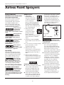
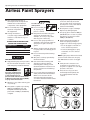
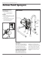
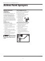
 Operating and Assembly Instructions
Please read and save these instructions. Read carefully before attempting to assemble, install, operate or maintain the product described. Protect yourself and
others by observing all safety information. Failure to comply with instructions could result in personal injury and/or property damage! Retain instructions for
future reference.
Airless
Paint Sprayers
For questions, parts and accessories: 1-800-626-4401
Models PS120B
© 2011 Campbell Hausfeld/Scott Fetzer
For parts, product & service information
visit www.chpower.com
IN425801AV 6/11
Operating Instructions and Assembly Instructions
Airless Paint Sprayers
Description
Table of Contents
Airless paint sprayers are capable of spraying a wide variety
of latex, oil-based, and alkyd paints, as well as stains,
preservatives and other non-abrasive finishes.
Description. . . . . . . . . . . . . . . . . . . . . . . . . . . . . . . . . . . . . . . 2
Application Chart. . . . . . . . . . . . . . . . . . . . . . . . . . . . . . . . . . 2
Safety Guidelines. . . . . . . . . . . . . . . . . . . . . . . . . . . . . . . . . . 3
General Safety Information . . . . . . . . . . . . . . . . . . . . . . . . . 3
Assembly Instructions . . . . . . . . . . . . . . . . . . . . . . . . . . . . . . 6
Preparation. . . . . . . . . . . . . . . . . . . . . . . . . . . . . . . . . . . . . . . 6
Spraying Instructions. . . . . . . . . . . . . . . . . . . . . . . . . . . . . . . 8
Cleanup. . . . . . . . . . . . . . . . . . . . . . . . . . . . . . . . . . . . . . . . . 10
Storage. . . . . . . . . . . . . . . . . . . . . . . . . . . . . . . . . . . . . . . . . 14
Spray Gun Maintenance . . . . . . . . . . . . . . . . . . . . . . . . . . . 15
Maintenance Chart . . . . . . . . . . . . . . . . . . . . . . . . . . . . . . . 16
Specifications. . . . . . . . . . . . . . . . . . . . . . . . . . . . . . . . . . . . 17
Replacement Parts. . . . . . . . . . . . . . . . . . . . . . . . . . . . . . . . 18
Troubleshooting. . . . . . . . . . . . . . . . . . . . . . . . . . . . . . . . . . 20
Force Feeding Pump . . . . . . . . . . . . . . . . . . . . . . . . . . . . . . 22
Warranty. . . . . . . . . . . . . . . . . . . . . . . . . . . . . . . . . . . . . . . . 24
These sprayers are also powerful and versatile enough to
be used with a variety of options (roller attachment, extra
lengths of hose, etc.) to make it an even more efficient tool.
NOTE: Guns pictured in illustrations may be different than
the one included with your unit.
Application Chart
Coating
Can Use
Do Not Use
Tip Size
Spray Pressure
Oil Base Stain
x
.011 - .013”
800 + psi
Wood Sealer
x
.011 - .013”
800 + psi
Concrete Sealer
x
.011 - .013”
800 + psi
Enamel
x
.011 - .013”
1500 + psi
Varnish
x
.011 - .015”
1500 + psi
Non-Metal Flake Aluminum Paint
x
.011 - .015”
1500 + psi
Vinyl Latex Paint
x
.013 - .015”
1700 + psi
Vinyl / Acrylic Latex Paint
x
**.013 - .015”
1700 + psi
Acrylic Latex Paint
x
.013 - .015”
1700 + psi
Oil Base Paint
x
.013 - .015”
1700 + psi
Oil and Water Based Primer
x
.013 - .015”
1700 + psi
V. V/A & A Latex Stain
x
.013”
1700 + psi
Textured Coatings
x
N/A
Elastomerics
x
N/A
Asphalt Coating
x
N/A
Wood Restorer
x
N/A
Block Filler
x
N/A
All Other Materials Not Listed - Call Technical Support at 1-800-626-4401.
www.chpower.com
2
Operating Instructions and Assembly Instructions
Airless Paint Sprayers
Safety Guidelines
Important Safety Instructions
Save These Instructions
This manual contains information
that is very important to know
and understand. This information
is provided for SAFETY and to
PREVENT EQUIPMENT PROBLEMS.
To help recognize this information,
observe the following symbols.
Danger indicates
an imminently
hazardous situation which, if not
avoided, will result in death or serious
injury.
Warning indicates
a potentially
hazardous situation which, if not
avoided, could result in death or
serious injury.
Caution indicates a
potentially
hazardous situation which, if not
avoided, MAY result in minor or
moderate injury.
General Safety
1. SAVE THESE
INSTRUCTIONS - To
reduce the risks of fire
or explosion, electrical
shock, and injury to
persons, read and understand
all instructions included in this
manual. Be thoroughly familiar
with the controls and the proper
use of the equipment.
MANUAL
2. Always wear a mask
or respirator and
eye protection when
painting. Be certain
mask or respirator
will provide necessary protection
against inhalation of harmful
vapors.
3. Keep visitors away and NEVER
allow children or pets in the work
area.
4. Do not smoke or eat when spraying
paint, insecticides, or other
flammable substances.
Unpacking
5. Always work in a clean
environment. To avoid injury and
damage to the workpiece, do not
aim the spray gun at any dust or
debris.
Notice indicates
important
information, that if not followed, may
cause damage to equipment.
After unpacking the unit, inspect
carefully for any damage that may
have occurred during transit. Make
sure to tighten fittings, bolts, etc.,
before putting unit into service.
Do not operate
unit if damaged
during shipping, handling or use.
Damage may result in bursting and
cause injury or property damage.
General Safety Information
California proposition 65
This product or its
power cord may
contain chemicals, including lead,
known to the State of California to
cause cancer and birth defects or other
reproductive harm. Wash hands after
handling.
6. When spraying and cleaning,
always follow the instructions and
safety precautions provided by the
material manufacturer (Refer to
MSDS).
Electrical Shock Hazard:
● Follow all local electrical and safety
codes, as well as the National
Electrical Code (NEC) and in the
United States, the Occupational
Safety and Health Act (OSHA).
● This product must be grounded.
In the event of an electrical short
circuit, grounding reduces the risk
of electric shock by providing an
escape wire for the electric current.
This product is equipped with a
cord having a grounding wire with
an appropriate grounding plug.
The plug must be plugged into an
outlet that is properly installed and
grounded in accordance with all
local codes and ordinances.
Grounded
Outlet
TEST
Grounding
Pin
RESET
Grounded
Outlet Box
Figure 1 - Grounding
Improper
installation of the
grounding plug is able to result in a risk
of electric shock.
● When repair or replacement of
the cord or plug is required, do
not connect the grounding wire to
either flat blade terminal. The wire
with insulation having an outer
surface that is green with or without
yellow stripes is the grounding wire.
● Check with a qualified electrician
or serviceman when the grounding
instructions are not completely
understood, or when in doubt as
to whether the product is properly
grounded. Do not modify the
plug provided; if it does not fit
the outlet, have the proper outlet
installed by a qualified electrician.
● This product is for use on a nominal
120 V circuit and has a grounding
plug similar to the plug illustrated in
Figure 1. Only connect the product
to an outlet having the same
configuration as the plug. Do not
use an adapter with this product.
www.chpower.com
3
Operating Instructions and Assembly Instructions
Airless Paint Sprayers
● High pressure spray is able to inject
toxins into the body and cause
serious bodily injury. In the event
that injection occurs, seek medical
attention immediately.
● Only qualified electricians or
service personnel should perform
maintenance on the electrical
components of this equipment.
To reduce the risk of
skin injection:
● Do not modify any of the
electrical components of
this equipment.
● Do not aim the gun
at, or spray, any
person or animal.
● If using an extension
cord, use only grounded three wire
extension cords that are in good
condition.
● Keep hands and other body parts
away from the discharge. For
example, do not try to stop leaks
with any part of the body.
● This spray gun is rated for 3000 psi
(20 500 kPa). Do not use on systems
designed to produce more than
3000 psi (20 500 kPa).
● Do not clean spray tip while it is
attached to the spray gun. Remove
spray tip from gun to clean tip
guard.
● Always engage the trigger lock
when not spraying. Verify the
trigger lock is functioning properly.
Appropriate Extension Cord
Gauge for given lengths
Length of Cord
Gauge
25’
14
25-50’
12
50-100’
10
Skin Injection Hazard:
● High pressure spray can inject toxins
into blood stream. If injection occurs,
seek emergency medical treatment.
Use a
face mask/respirator and
protective clothing when
spraying. Always spray in
a well ventilated area to
prevent health and fire hazards. Refer
to Material Safety Data Sheets (MSDS)
of spray material for details.
● Always use the nozzle tip guard. Do
not spray without nozzle tip guard
in place.
● Do not remove tip while cleaning
the pump.
● Only use a nozzle tip specified by
the manufacturer.
● Use caution when cleaning and
changing nozzle tips. Before
removing the nozzle tip, follow
the manufacturer’s instructions for
turning off the unit and relieving
the pressure.
● Do not leave the unit energized or
under pressure while unattended.
When not in use turn off the
unit and relieve the pressure in
accordance with the manufacturer’s
instructions.
● Never try to stop leaks with any part
of your body.
● This system is capable of producing
2800 psi (19 300 kPa). Use only
Campbell Hausfeld replacement
parts rated at 2800 psi (19 300 kPa)
or higher.
www.chpower.com
4
● Check parts for signs of damage.
Replace any damaged parts.
• To lock (engage): rotate tabs on
lock to horizontal position.
• To unlock (disengage) to spray:
rotate tabs on lock to vertical
position.
NOTE: If gun sprays while in the locked
position follow instructions in Spray
Gun Maintenance section for trigger
lock.
● Verify that all connections are
secure before operating. Do not
use pliers to tighten or loosen high
pressure connections.
● Know how to stop your unit
and bleed pressure quickly. Be
thoroughly familiar with the
controls.
LOCKED
TO UNLOCK
UNLOCKED
TO LOCK
Operating Instructions and Assembly Instructions
Airless Paint Sprayers
● Motor is equipped with an
automatic thermal overload. Motor
will restart without warning, after cooling.
Never aim or
spray at yourself
or anyone else or serious injury could
occur.
Relieve pressure before servicing or
resting:
1. Turn the Prime/Spray Control to the
Prime position.
2. Turn the pressure control knob to
Low Pressure position (CCW).
3. Turn power switch to OFF position
and unplug the power cord.
4. With gun pointed in a safe direction,
pull the gun trigger, with the
trigger lock disengaged.
5. Engage trigger lock.
● Simply turning off the pump motor
will not relieve pressure from
system. The above procedure must
be followed.
FIRE OR EXPLOSION HAZARD:
● Do not use solvents with flash points
less than 70°F (21°C) to clean this
equipment (examples of acceptable
cleaning solvents are water or
mineral spirits. A partial example list
of unacceptable cleaning solvents
are low flash napha, mek, acetone,
alcohol and toluene).
● Use only conductive or grounded
high-pressure airless paint sprayer
hoses specified by the manufacturer.
● Verify that all containers and
collection systems are grounded to
prevent static discharge.
● Do not spray pump assembly.
● Have fire extinguisher equipment
present and working.
Do not
spray
flammable materials in
vicinity of open flame
or near ignition sources.
Motors, electrical equipment and
controls can cause electrical arcs that
will ignite a flammable gas or vapor.
Never store flammable liquids or gases
in the vicinity of the unit.
Do not spray acids,
corrosive materials,
toxic chemicals, fertilizers or pesticides.
Using these materials could result in
death or serious injury.
● Do not use fuels to clean this
equipment.
● Keep spray area well ventilated.
Keep a good supply of fresh air
moving through the spray area.
Keep pump assembly in well
ventilated area.
● Remove all ignition sources (i.e.
Static electricity, pilot lights,
cigarettes and electrical arcing).
● Airless spraying can cause static
electricity. Always ground the pump
and spraying surface. Always use a
3-wire grounded extension cord and
power receptacle. Do not use 3 to 2
adapters.
● Do not use paints or solvents
containing halogenated
hydrocarbons such as methyl
bromine, carbon tetrachloride, and
ethyl iodine.
Keep hose away
from sharp objects.
Bursting hoses may cause injury.
Examine hoses regularly and replace if
damaged.
● Check hoses for weak or worn
condition before each use, making
certain that all connections are
secure.
● Keep area clean and free of paint or
solvent containers, rags, and other
flammable materials.
To reduce the risk of injury:
● Do not spray acids,
corrosive materials, toxic
chemicals, fertilizers, or
pesticides. Using these
materials could result in
death or serious injury.
● Do not kink or over-bend the hose.
● Do not expose the hose to
temperatures or to pressures in
excess of those specified by the
manufacturer.
● Do not use the hose as a strength
member to pull or lift the
equipment.
● Always wear appropriate gloves, eye
protection, and a respirator or mask
when painting.
● Always work in a clean environment.
Do not aim the spray gun at any
dust or debris.
● Do not operate or spray near
children. Keep children, pets, and
visitors away from equipment and
work area at all times.
● Do not over reach or stand on an
unstable support. Keep effective
footing and balance at all times.
● Stay alert and watch what you are
doing.
● Do not operate the equipment when
fatigued or under the influence of
drugs or alcohol.
Failure to follow
these instructions
can result in
serious injury
including death.
www.chpower.com
5
Operating Instructions and Assembly Instructions
Airless Paint Sprayers
Assembly Instructions
Tools required:
u 3/4 in. or Adjustable Wrench
Pump Assembly
u 5/8 in. or Adjustable Wrench
Assembly
1. Open packaging and check contents.
2. Remove the equipment and all parts
from the carton.
3. Attach high pressure hose to pump
and spray gun using a 3/4 inch
wrench (See Figure Below).
Power Switch
Bypass
Tube Clip
Bypass
Tube
Suction
Tube
Pressure
Control
Knob
Outlet
Valve
Prime/
Spray
Control
Suction
Filter
FIgure - Attach hose
Preparation
Airless painting systems, unlike most
other power tools, require additional
care to ensure proper working order.
Following these instructions will
significantly increase the likelihood
of having a positive paint experience.
It is important that the painting
equipment is flush/tested EACH
time a new job is started. Each
pump is tested at the factory with a
fluid that must be flushed from the
www.chpower.com
6
system prior to painting. It is also
required prior to each successive use
to flush the storage lubricant from the
system. Flush the system with either
water or mineral spirits. Use water if
spraying water based coatings or use
mineral spirits if spraying oil based
coatings.
Operating Instructions and Assembly Instructions
Airless Paint Sprayers
Preparation (Continued)
Starting Instructions
1. Place both suction and bypass tubes
in cleaning solvent.
1
2. Turn prime/spray control to the
Prime position.
3. Turn power switch to the ON
position.
4. Turn pressure to High (completely
clockwise). In a few seconds,
cleaning solvent will begin to move
up through the tube. Allow the fluid
to circulate for one minute to ensure
all air has been exhausted from the
pump.
Place Suction Tube
and Bypass Tube in
Solvent
2
3
5. Turn prime/spray control to Spray
position. Watch for any fluid leaks
(See Troubleshooting Chart if leaks
occur).
NOTE: If unit is building pressure
properly the pump should turn off,
which indicates it has reached its user
set pressure.
6. When flushing the system with
cleansing fluid (either prior to
use with paint or during cleaning
process) the spray tip can remain in
the clean position.
7. Point spray gun into an empty waste
bucket and pull trigger. To reduce
splashing, direct the fluid stream
along the inside of the bucket wall
and well above the fluid level.
Turn Prime/ Spray
Control
to PRIME
(knob is vertical)
Power Switch
Location
5
4
Turn Pressure
to HIGH
(completely clockwise)
6
Turn Prime/ Spray
Control
to SPRAY
(knob is horizontal)
7
Tip in
Cleaning
Position
While Pulling Trigger,
Direct Fluid Stream Along
Inside of Bucket
www.chpower.com
7
Operating Instructions and Assembly Instructions
Airless Paint Sprayers
Preparation (Continued)
9. After completing the flush/testing
process, purge the pump of fluid.
10.Repeat the preceding steps using
paint instead of cleaning solvent.
NOTE: Strain and thin paint before
using. All paint may have particles that
will clog filter and spray tips. Remove
any skin which may have developed on
the paint due to air exposure. Follow
paint manufacturers’ recommendations
on thinning paint.
11.When pure paint appears from
spray tip rotate tip to the Spray
position. The system is now ready
for use.
Spraying Instructions
12”
Professional looking results can be
obtained by following the spray tips
below.
1
1. Keep the gun perpendicular to the
surface.
Always hold the gun perpendicular
to the surface with the tip
approximately 12 inches from the
surface. If held at an angle (up
and down or side to side), paint
will build up unevenly, leave the
work splotchy, and cause excessive
overspray (See Figure to the right).
2. Move with a smooth arm stroke.
Move the gun at a steady, even
pace while keeping the gun
perpendicular to the surface (See
Figures to the right). Do not fan
the gun. Fanning the gun will cause
excessive overspray and uneven
coverage (See Figure to the right).
3. Start moving the gun before
triggering.
To get a smooth overlap and prevent
initial paint buildup, start your
stroke movement before pulling the
trigger. Release the trigger before
stopping at the end of the stroke
(See Figure to the right).
NOTE: To assure uniform paint
coverage, overlap each stroke by 20%
- 30% and use two coats with a cross
pattern (one coat horizontal, second
coat vertical).
Clean Position
Holding Spray Gun
Thin Coat
Overspray
Heavy
Coat
2
Thin Coat
Overspray
rrect
Inco
Spray Position
Result of Flexing Wrist While Spraying
Approx.
10-12”
Release
Trigger
Pull
Trigger
End
Stroke
Start
Stroke
Proper Way to Trigger Spray Gun
www.chpower.com
8
Water
Prevent clogged tip
Operating Instructions and Assembly Instructions
Airless Paint Sprayers
Spraying Instructions
(Continued)
INTERMITTENT USE
If you are spraying and decide to stop
for several minutes, lock the spray
gun trigger and submerge the tip in
a container of water (See Figure on
page 8). This will prevent paint from
hardening in the tiny spray opening
and clogging the tip. Be sure to release
the pressure in the system and turn the
unit off.
CLEARING CLOGS
REVERSIBLE TIP: (Included)
1. Rotate the tip to the clean position
(See Figure 1 on page 8).
2. Point gun in a safe direction and
spray. This should clear tip of any
blockage.
3. Rotate the tip back to the spray
position and continue spraying (See
Figure 2 on page 8).
4. If clogging continues, replace gun
filter and consider straining the
paint prior to use.
HOW TO CHANGE SPRAY TIPS
It may be necessary to change spray tips
during a paint job. Follow these steps
for safe, easy tip changes.
1. Depressurize and turn off unit per
manufacturer’s instructions.
2. Engage gun trigger lock.
3. Pull red tip insert
out of spray base
and replace with
different tip, fully
inserting tip into base.
HOW TO ATTACH ROLLER ACCESSORY
1. Depressurize and turn off unit per
manufacturer’s instructions.
2. Engage gun trigger lock.
3. Remove spray base, tip, seal and
washer assembly.
4. Attach roller accessory (AL2275
shown) to airless spray gun. If
needed use thread adapter and
washer between roller and spray gun
as shown.
Equipment damage
can occur if a needle
or sharp object is used to clean the tip.
Tungsten carbide is brittle and can be
chipped.
Figure - Attach roller accessory to spray gun
www.chpower.com
9
Operating Instructions and Assembly Instructions
Airless Paint Sprayers
Cleanup
Temporary Cleanup
cleanup for OVERNIGHT STORAGE
NOTE: Cleaning and maintenance
of the pump are the most important
steps you can take to ensure proper
operation and a long life for your
airless paint sprayer. Please follow the
cleaning instructions carefully and . . .
1
2
WEAR ALL NECESSARY
SAFETY GEAR
To Lock
Necessary Tools / Materials:
• One (1) bucket
• Water
• Plastic wrap
Locked
Engage Trigger Lock
Turn Prime/Spray
Control to PRIME
Position
When reusing the
sprayer with the
same paint the next day at the same
job site, it is not necessary to flush
the paint from the system. However,
it is important to keep air from
coming into contact with the
paint.
4
3
NOTE: Do NOT disconnect any hoses.
1. Turn prime/spray control to PRIME
position.
High pressure
hose may still be
pressurized with prime/spray control
in the PRIME position. With the gun
pointed in a safe direction, pull the
gun trigger to relieve any pressure in
the hose.
2. Engage gun trigger lock.
3. Place spray gun in bucket of water.
There should be enough water to
cover spray tip. This will prevent
paint from drying or clogging tip.
4. Leave suction and bypass tubes in
bucket of paint. Make sure ends
of suction and bypass tubes are
below surface of paint in bucket.
5. Cover bucket and tubes with plastic
wrap or a damp towel to prevent
film forming on paint. Or, if using
latex paint, pour a very thin layer of
water over top of paint. Stir water
into paint the next morning.
Water
Suction and Bypass Tubes
Remain in Bucket with Ends
Below Paint Surface
Place Gun in
Water
5
PAINT
or
Cover Bucket
PAINT
Latex Paint: Use Thin Layer of
Water to Cover Paint
www.chpower.com
10
Operating Instructions and Assembly Instructions
Airless Paint Sprayers
Cleanup for Changing Paints
or Temporary Storage for
More Than One Night
WEAR ALL NECESSARY
SAFETY GEAR
Cleaning Pump
1
2
Necessary Tools / Materials:
• Rag
• Gloves
• Two (2) buckets
• At least one (1) gallon of cleaning fluid (water or mineral spirits
depending on coating type)
•Cleaning brush
Turn power switch to ON
(shown in the OFF position)
NOTE: Do NOT disconnect any hoses.
1. Turn prime/spray control to PRIME
position.
2. Turn power switch to ON.
Turn Prime/Spray
Control to PRIME
Position
High pressure
hose may still be
pressurized with prime/spray control
in the PRIME position. With the gun
pointed in a safe direction, pull the
gun trigger to relieve any pressure in
the hose.
3
4
3. Turn pressure to HIGH (completely
clockwise).
4. Lift suction assembly above fluid
level in bucket.
While holding suction assembly
above paint level, allow pump to
run until empty.
5. Immediately place both suction
assembly and bypass tube in a
bucket containing enough cleaning
fluid to cover suction filter by two
inches. Allow pump to prime and
begin circulating fluid.
Turn Pressure to HIGH
(completely clockwise)
5
Lift Suction Assembly above
Paint Level in Bucket
6
6. While fluid is circulating, soak rag
in fluid and wipe exterior of suction
assembly and bypass tube. Remove
suction filter. Wipe suction filter
with rag removing excess paint
buildup. Reinsert filter into suction
tube.
Suction Assembly and
Bypass Tube in Bucket
of cleaning fluid
Wipe Exterior of Suction
Assembly and Bypass Tube
www.chpower.com
11
Operating Instructions and Assembly Instructions
Airless Paint Sprayers
Cleanup for Changing Paints
or Temporary Storage for
More Than One Night (Continued)
Allow the cleaning fluid to continue
circulating for approximately 10
minutes.
Cleaning Hose and Gun
8
7
9
7. Turn pressure to HIGH (completely
clockwise).
8. Turn prime/spray control to SPRAY
position.
Turn Prime/ Spray
Control to SPRAY (knob
is horizontal)
9. Rotate spray tip to CLEAN position.
10.Point spray gun into bucket of
paint and pull trigger.
NOTE: To reduce splashing, direct
fluid stream along inside of bucket
and above the paint level.
11.As soon as cleaning fluid is flowing
from spray gun, release trigger.
NOTE: It should take less than one
minute to clear each 25 feet of high
pressure hose.
If Reversible Tip is
Used, Rotate Spray Tip
to CLEAN Position.
Turn Pressure to HIGH
(completely clockwise).
12
10
To Lock
Locked
Engage Gun Trigger Lock
12.Engage gun trigger lock.
13.Turn prime/spray control to PRIME
position.
13
14.Turn pressure control to HIGH.
15.Lift suction assembly above fluid
level in bucket.
NOTE: Allow pump to run until
empty.
16.Repeat process (1 - 15) with
fresh cleaning fluid, to remove
contaminated cleaning fluid from
initial cleaning.
Paint
While Pulling Trigger,
Direct Fluid Stream Along
Inside of Bucket
14
Prime Position
15
High Pressure Position
(completely clockwise)
Lift Suction
Assembly
www.chpower.com
12
Operating Instructions and Assembly Instructions
Airless Paint Sprayers
Cleanup for Changing Paints or
Temporary Storage for More
Than One Night (Continued)
17.Make sure prime/spray control is in
SPRAY position to reduce dribbling.
Finishing Touches/Shutdown
17
18.Turn pressure to LOW (completely
counterclockwise).
19.Turn power switch to OFF position.
20.With gun pointed in safe direction
pull trigger with lock released to
relieve any pressure in hose.
Prime/Spray
is in SPRAY
Position
21.Engage gun trigger lock.
22.Clean buckets and dispose of any
waste paint and cleaning fluid in
an environmentally responsible
manner.
18
23.Clean tip guard with cleaning brush
and cleaning fluid.
NOTE: At this point, pump, hose and
spray gun are clean, but still require
further preparation for storage of more
than one day.
20
Turn Pressure to LOW
(completely counterclockwise)
Pull Gun Trigger with
Trigger Lock Released
21
To Lock
Locked
Engage Gun Trigger Lock
www.chpower.com
13
Operating Instructions and Assembly Instructions
Airless Paint Sprayers
Storage
short term
(less than one week)
Water Based Paint
1
WEAR ALL NECESSARY
SAFETY GEAR
Necessary Tools / Materials:
• Pump Protector Solution
PUMP
PROTECTION
SOLUTION
2
Pump
Protector
• Plastic Wrap
WASTE
BUCKET
• 3/4 in. or Adjustable Wrench
Oil or Alkyd Based Paint
If sprayer cleaned with mineral spirits,
simply wrap suction filter housing in
plastic to keep debris out of suction
filter. No other preparation is necessary.
Place Suction Assembly in
Solution
Prepare Pump
Protector Solution
Water-based paint
1. Prepare Pump Protector solution in
bucket as directed on container.
4
3
PUMP
PROTECTION
SOLUTION
PUMP
PROTECTION
SOLUTION
2. Place suction assembly into solution.
3. Place end of bypass tube into waste
bucket.
4. With prime/spray control in PRIME
position, turn pressure to HIGH
(completely clockwise).
5. Turn power switch ON. Circulate
Pump Protector through bypass
tube until bucket of solution is
EMPTY.
WASTE
BUCKET
WASTE
BUCKET
With Prime/Spray
Control in PRIME
Position, Turn
Pressure to HIGH
(completely clockwise)
Place End of Bypass Tube
into Waste Bucket
6. Turn pressure to LOW (completely
counterclockwise).
7. Wrap suction filter housing in
plastic to keep debris out of suction
filter.
long term
(more than one weeK)
7
6
PLASTI
8. Remove high pressure hose and
drain. Reassemble high pressure
hose to pump.
9. With spray tip attached to spray
gun, wrap tip with plastic to protect
tip.
C WRAP
Wrap Suction Filter
Housing in Plastic
Turn Pressure to LOW
(completely counterclockwise)
www.chpower.com
14
Operating Instructions and Assembly Instructions
Airless Paint Sprayers
Spray Gun Maintenance
Pump damage may
occur if these
instructions are not followed.
Before performing
any maintenance,
make sure to relieve pressure from
system and disconnect power from
sprayer.
•Do not use oil based solvents to
clean equipment after using latex
based coatings. Use only warm soapy
water.
TIP SEAL AND WASHER
Occasionally, you will need to replace
the silver seal and clear washer located
inside the tip base.
1. To replace seal and washer, first
loosen tip base with adjustable
wrench, and then remove by hand.
2. Remove spray tip.
3. With Phillips screwdriver, push seal
and washer out from front of tip
base.
• Always replace clogged gun filters,
do not attempt to clean them.
4. With flat side of seal facing up, place
seal in base. Make sure it lines up
properly with base.
•Carefully follow cleaning and
storage instructions for your sprayer.
5. Place washer in base. Make sure it
lines up properly with base.
•Do not use metal or other hard
objects to pick dried paint material
from Spray Tip Orifice.
6. Put spray tip back in tip base.
TRIGGER LOCK
7. Reattach tip base to gun valve.
Pulling the trigger
must not open the
gun valve when
trigger lock is activated.
Make sure spray
tip and tip base fit
snugly in place. A
loose fit can lead to misdirected spray
discharge and a skin injection hazard.
You should be able to get the actuator
(#12, page 19) to wiggle slightly with
your finger while holding the trigger
against the trigger lock when it is in the
locked position. If you cannot, adjust
the trigger position by following these
instructions:
1. Place trigger in locked orientation
(tabs horizontal).
2. With one hand holding trigger
lightly against lock, use a 1/4 inch
nut driver to turn nut (#13, page 19)
in until trigger starts to come off the
lock.
3. Reverse the nut (counterclockwise)
1/2 turn.
www.chpower.com
15
Operating Instructions and Assembly Instructions
Airless Paint Sprayers
Maintenance Chart
Maintenance
Item
Check
Replace
User
Serviceable
Product safety labels
Before each use
As required
Yes
Call for location of product safety labels
and related part numbers.
Trigger adjustment
Before each use
Yes
See trigger lock warning under Spray
Gun Maintenance.
Airless hose
Before each use
Yes
Read information on the hang tag
attached to the high pressure hose for
instructions on maintenance.
Sealing surfaces
Before each use
Yes
Make sure they are clean.
Suction tube
Before each use
As required
Yes
Check for nicks and cuts.
Bypass tube
Before each use
As required
Yes
Check for nicks and cuts.
Suction filter
Before each use and
every 5 gal.
As required
Yes
Gun filter
Before each use
Every 25 gal.
Yes
Roller nap
Before each use and
every 5 gal.
As required
Yes
Does not
require
replacement
with normal
use
* Call
Pressure switch and
prime/spray valve
Detail Notes
Do not attempt to clean gun filter, only
replace.
Inlet valve
Before each use
Yes
7/8” Wrench, torque to 150 in/lbs.
Outlet valve
Before each use
Yes
5/8” Wrench torque to 150 in./lbs.
Spray tip
Before each use
Yes
1” Wrench torque to 135 in/lbs.
Every 20-75
gal.
* Call 1-800-626-4401
www.chpower.com
16
Operating Instructions and Assembly Instructions
Airless Paint Sprayers
Specifications
Operating Pressure
Power
Ratings
Safety Features
0-2800 psi
120 Volts AC
Spray gun trigger lock
60 Hz
Spray gun trigger guard
7,0 Amps
Spray gun pressure diffuser
Prime/Spray valve over
pressure relief
Capacity (GPM)
Model
Weight
(lbs.)
@ 0 psi
@ 2000 psi
Maximum
Maximum
Hose Length Tip Size
PS120B
14 lbs.
0.28
0.24
50 ft.
.015 in.
www.chpower.com
17
Operating Instructions and Assembly Instructions
For Replacement Parts and Accessories,
Call 1-800-626-4401
Please provide following information:
- Model number
- Serial number (if any)
- Part descriptions and number as shown in parts list
Address parts correspondence to:
Campbell Hausfeld
Attn: Customer Service
100 Mundy Memorial Dr.
Mt. Juliet, TN 37122 U.S.A.
2
1
3
4
8
5
7
6
9
Replacement Parts List
Ref
No.
Description
Part No.
1
Stand
AL168650SJ
1
2
Gun assembly (with 0.013" insert, tip)
AL2150
1
2a
0.013" Tip insert
AL2213
1
2b
0.015" Tip insert
AL2215
1
3
Motor cover with 2 decals
AL168620SJ
1
4
25' black hose
HA211301AV
1
5
Suction bypass assembly (includes suction filter)
AL168805AV
1
6
Inlet valve kit
AL168300SJ
1
7
Front cover kit
AL168600SJ
1
8
Outlet valve
AL168341SJ
1
9
Suction filter
AL168820AV
1
www.chpower.com
18
Qty.
Operating Instructions and Assembly Instructions
For Replacement Parts and Accessories,
Call 1-800-626-4401
Please provide following information:
- Model number
- Serial number (if any)
- Part descriptions and number as shown in parts list
Address parts correspondence to:
Campbell Hausfeld
Attn: Customer Service
100 Mundy Memorial Dr.
Mt. Juliet, TN 37122 U.S.A.
1 or 2
12
13
14 (2x)
11 (2x) 20
3
9
8
21 (4x)
7
6
5
4
22 or 23
16
15
19
17
14
18
Replacement Parts List
Ref.
No.
Description
1
2
3
4
5
6
7
8
9
10
11
12
13
14
15
AL2150 - Black (Std)
AL1860 - Metal (Pro)
Part
No.Qty.
Kit, Black Gun Left Grip, Lock
and Guard
AL184401SV
Kit, Pro Gun Left Grip, Lock
and Guard
AL184400SV
Insert, Gun
AL179803AG
Kit, Pro Stem and Diffuser
(includes #7)
AL183400SV
Spring, Gun
AL048600AV
Retainer, Gun Spring
AL020201AV
Seal, Gun
AL020300AV
Washer, Seal
AL153801AV
Washer, Gun Seat Retainer
AL005404AV
Kit, Gun Seal (Includes #7, #8, #9)AL183600SV
Pin, Gun Actuator
AL024102AV
Actuator, Gun
AL182700AV
Nut, #5-40 Hex Lock
ST073804AV
Kit, Gun Trigger (Trigger, Screws)AL183100SV
Gun Filters,
100 Mesh (yellow)
AL086101AJ
50 Mesh (white)
AL086100AJ
1
1
1
1
1
1
1
1
1
1
2
1
1
1
Ref.
No.
Description
Part
No.Qty.
16
Washer, Long Filter
17
Adapter, Long Filter
18
Assembly, Pro Gun Swivel
(optional)
19
Guard, Pro Gun Trigger
20
O-Ring
21
Screw, #5-40 x 5/16” SHC
22
Grip, Right, Pro Gun
23
Grip, Right, Black Gun
Additional Items Available:
Kit, Pro Gun Valve –
Includes #4 - #9, #13
Kit, Gun Actuator –
Includes #11, #12, #13
Kit, Pro Gun Insert –
Includes #3 - #9, #16
Kit, Pro Gun Full Grip –
Includes #2, #19 - #22
MJ105402AV 1
AL072301AV 1
AL183500AJ
AL184600AV
MJ106511AV
MJ103804AV
AL184302AV
AL184301AV
1
1
1
4
1
1
AL183200SV
AL183700SV
AL184100SV
AL184500SV
2 pk
2 pk
www.chpower.com
19
Operating Instructions and Assembly Instructions
Troubleshooting Chart
Symptom
Possible Cause(s)
Corrective Action
Motor hums and does not run
1. Supply voltage too low
1. Do not use an extension cord, it is better to add hose length.
Use portable generator with a 2400 VA minimum rating
Motor does not run or hum
2. Power Switch is in OFF position
3. Pressure knob is set to zero.
2. Flip Power Switch to ON position
3. Turn pressure knob clockwise to increase pressure.
4. Bad power connection
4. Check power connections at power receptacle, along extension
cord and at equipment for looseness or damage
5. Circuit breaker or fuse is tripped
5.Correct cause of circuit overload. (Possible causes: Supply
voltage too low, extension cord too long for available supply
voltage, or motor has been damaged.)
6. Thermal overload protection
activated
6. Allow motor to cool for approximately 30 minutes, determine
cause and restart motor. (Possible causes: Supply voltage too
low, extension cord too long for available supply voltage, or
motor has been damaged.)
7. Check valves stuck
7. “Pop” Inlet Valve and Outlet Valves. Call 1-800-626-4401
8. Suction Assembly loose and/or
sealing surfaces are dirty at Inlet
Valve
8. Remove Suction Assembly, clean sealing surfaces and
reassemble
9. Suction Head not immersed in
paint
9. Add more paint to bucket and/or adjust position of Suction
Assembly
10.Prime/Spray Control is in the
spray position
10.Turn the Prime/Spray Control to the Prime position
Motor runs, but pump does
not prime even though it was
working just fine a little while
ago. (Usually occurs after
moving or adding more paint
to the paint bucket.)
11 See Possible Causes 8, 9, 10
11.See Corrective Actions 8, 9, 10
12.Clogged suction filter
12.Remove suction filter and clean. Also, refer to Maintenance
section
13.Trash caught in valves
13.See “Force Feeding” figure on page 22
14.Paint sediments settled to
bottom of bucket
14.Strain and mix paint thoroughly
Pump primes, but does not
build pressure
15.Prime/Spray Control not in Spray
position
15.Turn Prime/Spray Control to Spray position
16.Pressure Control not set to high
enough pressure
16.Turn Pressure Control clockwise to desired pressure. Fully
clockwise is maximum pressure
17.Even though Prime/Spray
Control is in Spray position, fluid
still flows from By-Pass Tube.
Prime/Spray Control is worn or
damaged
17. Call 1-800-626-4401
18.Clogged gun filter
18.Replace with new filter. Do not attempt to clean gun filters.
Also, refer to Maintenance section
19.Clogged Spray Tip
19.See Clearing Clogs section
20 A. Tip is damaged or worn
20.A. Replace tip. Also, refer to Maintenance section
Motor runs, but pump does
not prime after being cleaned
after last use. (This problem
can usually be prevented by
following the recommended
cleaning and storage
procedure)
Pump primes and builds
pressure, however, the
equipment does not spray or
produce a quality spray pattern
B. Paint requires thinning
B. Follow paint manufacturers thinning recommendations.
Paint should not typically need to be thinned more than 8
oz. of solvent per gallon
C. Reversible Spray Tip in
cleaning position
C. Turn Spray Tip to Spray position. See Cleaning section for
details
Continued on next page
www.chpower.com
20
Operating Instructions and Assembly Instructions
Troubleshooting Chart (Continued)
Symptom
Possible Cause(s)
Corrective Action
Pump primes and builds
pressure, but does not maintain
pressure once trigger is pulled
21.Clogged Suction Filter
21.Remove Suction Filter and clean. Also, refer to Maintenance
section
22.Suction Assembly loose and/or
sealing surfaces are dirty at Inlet
Valve
22.Remove Suction Assembly, clean sealing surfaces and
reassemble
23.Paint thick due to cold weather.
This problem usually occurs with
Latex based coatings
23.Do not paint Latex coatings in temperatures less than 50°F
(10°C). Refer to paint manufactures minimum painting
temperature recommendations
24.Inlet Valve and/or Outlet Valve
are worn
24.Replace valves. Also, refer to Maintenance section
25.Trash caught in Gun Valve
25.Clean or replace Gun valve. Also, refer to Gun Maintenance
section. This is a very rare occurrence, and will not occur if filters
are properly maintained
26.Worn Gun Valve
26.Replace Gun valve. Also, refer to Gun Maintenance section
27.Dried paint under gun actuator
27.Remove 1/4” nut and gun actuator at rear of gun. Remove
dried paint from around needle and back of actuator. Replace
actuator and 1/4” nut. Set gun trigger position with trigger
lock in locked orientation (tabs horizontal) by the following
instructions: With one hand holding trigger softly against
lock, use a 1/4” nut driver to turn nut in until trigger starts to
come off the lock, then back off the nut (counterclockwise) 1/2
turn. Pulling the trigger must not open the gun valve when
trigger lock is activated. You should be able to get the actuator
to wiggle slightly with your finger while holding the trigger
against the locked trigger lock.
After moving equipment or
adding paint to bucket, unit
will not prime or spray
28.Suction assembly loose or
damaged
28.Tighten suction assembly onto inlet valve. Re-prime sprayer. If
problem is not remedied, consult Technical Support
Oil in Paint
29.Pump was not flushed prior to
use
29.Flush unit prior to use (See preparation section).
Fluid leaks
30.Loose connection
30.Clean sealing surface and reassemble per assembly instructions
31.Contaminated sealing surface
31.Consult technical support
32.Damaged component
32.Consult technical support
33.Possible product quality issue.
(We would greatly appreciate
your assistance in continuous
product quality improvement)
33.Call technical support at 1-800-626-4401
Gun will not shut-off
Symptoms not listed or
unsuccessful in resolving issue
www.chpower.com
21
Operating Instructions and Assembly Instructions
Airless Paint Sprayers
“Force Feeding” Pump
To remove trash that has been caught
in the valves, the unit can be force fed.
With pump on and prime/spray knob
turned to “prime” position, pour the
appropriate solvent into the suction
tube and then fold hose as shown
opposite. While firmly squeezing the
suction tube, slide hand down toward
the pump and repeat until pump
primes.
Notes:
• Weather conditions can cause unsatisfactory results when spraying some coatings.
• High humidity prolongs set, and cure times.
• High temperatures decrease set, and cure times.
•Cold temperatures extend set, and cure times.
• Variations in temperature, and humidity can cause variations in finish quality.
•Coating manufacturers can recommend additives to resolve some of these problems, and should be contacted for assistance
with particular problem resolutions.
www.chpower.com
22
Operating Instructions and Assembly Instructions
Notes
23
Operating Instructions and Assembly Instructions
Airless Paint Sprayers
Limited Warranty
1. Duration: From the date of purchase by the original purchaser as follows: Paint Application Systems - 1 year. All Paint Spray Guns and
Paint Application Accessories - 1 year.
2. Who Gives This Warranty (Warrantor): Campbell Hausfeld/A Scott Fetzer Company, 100 Production Drive, Harrison, Ohio, 45030,
Telephone: 1-800-626-4401.
3. Who Receives This Warranty (Purchaser): The original purchaser (other than for purposes of resale or rental) of the Campbell
Hausfeld Product.
4. What Products Are Covered By This Warranty: All non-compressor driven paint application systems, HVLP spraying systems, and
paint application accessories supplied or manufactured by the Warrantor.
5. What Is Covered Under This Warranty: Defects in material and workmanship which occur within the duration of the warranty
period. Warrantor will also cover normal wear items for a period of thirty days from the date of original purchase against defects in
material and workmanship. These wear items are: HVLP-filters, motor brushes, gun packing, gun canister seal, gun check valve and gun air
flow ring; Airless-inlet valve, outlet valve, gun valve, filters, tips, all seals and o-rings.
6. What Is Not Covered Under This Warranty:
A. Implied warranties, including those of merchantability and FITNESS FOR A PARTICULAR PURPOSE ARE LIMITED FROM THE DATE OF
ORIGINAL PURCHASE AS STATED IN THE DURATION. If this product is used for commercial or industrial purposes, the warranty will
be void. If product is used for rental purposes, the warranty will be void. Some states do not allow limitation on how long an implied
warranty lasts, so the above limitations may not apply to you.
B. ANY INCIDENTAL, INDIRECT, OR CONSEQUENTIAL LOSS, DAMAGE , OR EXPENSE THAT MAY RESULT FROM ANY DEFECT, FAILURE,
OR MALFUNCTION OF THE CAMPBELL HAUSFELD PRODUCT. Some states do not allow the exclusion or limitation of incidental or
consequential damages, so the above limitation or exclusion may not apply to you.
C. Any failure that results from an accident, purchaser’s abuse, neglect or failure to operate products in accordance with instructions
provided in the owner’s manual(s) supplied with product. Accident, purchaser’s abuse, neglect or failure to operate products in
accordance with instructions shall also include the removal or alteration of any safety devices. If such safety devices are removed or
altered, this warranty is void.
D. Normal adjustments which are explained in the owner’s manual(s) provided with the product.
E. Items or services that are normally required to maintain the product: HVLP-filters, motor brushes, gun packing, gun canister seal, gun
check valve and gun air flow ring; Airless-inlet valve, outlet valve, gun valve, filters, tips, all seals and o-rings., or any other expendable
part not specifically listed, will only be covered for thirty days from date of original purchase.
7. Responsibilities of Warrantor Under This Warranty: Repair or replace, at Warrantor’s option, products or components which are
defective, have malfunctioned and/or failed to conform within duration of the warranty period.
8. Responsibilities of Purchaser Under This Warranty:
A. Provide dated proof of purchase and maintenance records when calling 1-800-626-4401 for further instructions.
B. Use reasonable care in the operation and maintenance of the products as described in the owner’s manual(s).
9. When Warrantor Will Perform Repair or Replacement Under This Warranty: Repair or replacement will be scheduled and
serviced according to the normal work flow at the servicing location, and depending on the availability of replacement parts.
This Limited Warranty applies in the U.S. and Canada only and gives you specific legal rights. You may also have other rights which vary from
state to state, or country to country.
www.chpower.com
24