1
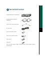
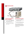
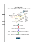
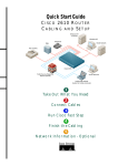
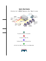
Quick Start Guide
C ATA LY S T 2 900 S E R I E S X L S W I T C H E S
Serial cable
10BaseT/
100BaseT
switch
10BaseT/
100BaseT
hub
Cisco IOS
command-line
interface
Crossover
cabling
SER
IES
1X
2X
SER
IES
Straight-through
cabling
10BaseT/
100BaseT
router
Web-based or
SNMP-based
management
station
10BaseT/
100BaseTX
workstations
1
TAKE OUT WHAT YOU NEED
2
CABLE THE SWITCH
3
ASSIGN SWITCH INFORMATION
45
ACCESS THE SWITCH FROM YOUR BROWSER
Take Out What You Need
Catalyst 2900 series XL Ethernet switch
Tighten
Screws
To Activate
1x
2x
WS-X2914-XL-V
1x
2x
3x
4x
5x
6x
7x
8x
3x
Tighten
Screws
To Activate
4x
10BaseT/100BaseTX
9x
10x
11x
WS-X2922-XL-V
12x
13x
14x
15x
16x
17x
18x
1X
1X
100BaseFX
19x
20x
100BaseFX
21x
22x
23x
24x
MODE
n
tio
la
al de
st ui
In G
se
ea s
el te
R o
N
Hardware installation guide and
release notes
RJ-45-to-RJ-45 rollover console cable
AC power cable
1
RJ-45-to-DB-9 serial connector
RJ-45-to-DB-9 terminal connector
Rack-mount kit
Rubber feet
Note: You need to supply a Category 5 straight-through or crossover cables to connect to
Ethernet devices.
Cable the Switch
Tighten
Screws
To Activate
1x
2x
WS-X2914-XL-V
1x
2x
3x
4x
5x
6x
7x
8x
3x
Tighten
Screws
To Activate
4x
10BaseT/100BaseTX
9x
10x
11x
WS-X2922-XL-V
12x
13x
14x
15x
16x
17x
18x
1X
1X
100BaseFX
19x
20x
100BaseFX
21x
22x
23x
24x
MODE
RJ-45
10/100 port
RJ-45-to-RJ-45
Cat 5 straightthrough cable
2
RJ-45
Ethernet port
Connect PCs, Workstations,
Servers, and Routers
1
2
Connect a Category 5 straight-through
cable (not supplied) to a 10/100 port on
the front panel of the switch.
Connect the other end of the cable to
the RJ-45 port of the PC, workstation,
server, or router.
Connect Switches and Hubs
1
Connect a Category 5 crossover cable
(not supplied) to a 10/100 port on the
front panel of the switch.
2
Connect the other end of the cable to an
RJ-45 port of the target switch or hub.
Note: Use a straight-through cable to
connect two ports when one of the ports is
designated with an X. Use a crossover cable
to connect two ports when both ports are
designated with an X.
DC INPUTS FOR REMOTE
POWER SUPPLY
SPECIFIED IN MANUAL.
+5V @24A, +12V @1.0A
RATING
100-120/200-240V
2.0A/1.0A 50-60HZ
DC INPUT
CONSOLE
RJ-45
console port
RJ-45-to-RJ-45
rollover cable
RJ-45-to-DB-9 adapter
(labeled TERMINAL)
Connect the AC Power Cord
1
Connect one end of the supplied AC
power cable to the switch rear panel.
Note: If you are connecting to a Cisco
600W AC redundant power system (RPS),
refer to the Catalyst 2900 Series XL
Installation Guide and the Cisco Redundant
Power System Hardware Installation Guide
for more information.
2
Connect the other end of the power
cable to a grounded AC outlet.
2
Connect the other end of the cable to a
terminal or PC with terminal-emulation
software. Use one of the supplied
adapters if you need to.
The terminal or emulation software
must match the settings on the console
port. Check your terminal or emulation
software to be sure it matches the
settings listed below, and reconfigure it if
it does not.
— 9600 baud
— No parity
Connect to Your Console
— 8 data bits
1
— 1 stop bit
Connect the supplied flat, blue, rollover
cable to the CONSOLE port on the
switch rear panel.
3
Assign Switch Information
The first time that you access the switch, it
runs a setup program that prompts you for
IP and other configuration information
necessary for the switch to communicate
with local routers and the Internet. This
information is also required if you plan to
use the Cluster Management Suite to
configure and manage the switch.
4
Note: If the switch will be a cluster
member managed through the IP address of
the command switch, it is not necessary to
assign IP information or a password. If you
are configuring the switch as a standalone
switch or as a command switch, you must
assign IP information. Refer to the Cisco
IOS Desktop Switching Software
Configuration Guide for more information.
IP Information Requirements
You will need the following information
from your system administrator:
•
Switch IP address
•
Subnet mask (IP netmask)
•
Default gateway (router)
•
Enable secret password
First-Time Startup
Use this procedure to assign IP information:
1
Enter Y at the first prompt.
Continue with configuration dialog?
[yes/no]: y
2
Enter the switch IP address, and press
Return:
Enter IP address: ip_address
3
Enter the subnet mask, and press
Return:
Enter IP netmask: ip_netmask
4
Enter Y at the next prompt to specify a
default gateway (router):
Would you like to enter a default
gateway address? [yes]: y
5
Enter the IP address of the default
gateway, and press Return.
IP address of the default gateway:
ip_address
6
Enter a host name for the switch, and
press Return.
Note: On a command switch, the host
name is limited to 28 characters; on a
member switch to 31 characters. Do not use
-n, where n is a number, as the last character
in a host name for any switch.
Enter a host name: host_name
7
Enter a secret password, and press
Return.
Note: The password can be from 1 to 25
alphanumeric characters, can start with a
number, is case-sensitive, and allows spaces
but ignores leading spaces.
Enter enable secret:
secret_password
8
Enter Y to enter a Telnet password:
Would you like to configure a
Telnet password? [yes] y
Note: The password can be from 1 to 25
alphanumeric characters, is case-sensitive,
allows spaces, but ignores leading spaces.
9
password telnet_password
snmp community private rw
snmp community public ro
cluster enable cls_name
end
13
— If the information is correct, enter Y
at the prompt, and press Return.
Enter the Telnet password, and press
Return:
— If the information is not correct,
enter N at the prompt, press
Return, and begin again at Step 1.
Enter Telnet password:
telnet_password
10
Enter Y to configure the switch as the
cluster command switch. Enter N to
configure it as a member switch or as a
standalone switch.
Note: If you enter N, the switch appears as
a candidate switch in Cluster Builder. In this
case, the message in Step 11 is not displayed.
Would you like to enable as a
cluster command switch? y
11
Assign a name to the cluster, and press
Return.
Enter cluster name: cls_name
Note: The cluster name can be 1 to 31
alphanumeric characters, dashes, or
underscores.
12
The initial configuration is displayed:
The following configuration command
script was created:
ip subnet-zero
interface VLAN1
ip address 172.20.153.36 255.255.255.0
ip default-gateway 172.20.153.01
hostname host_name
enable secret 5 $1$M3pS$cXtAlkyR3/6Cn8/
line vty 0 15
Verify that the information is correct.
Use this configuration? [yes/no]:y
Where to Go Next
After you complete the setup program, the
switch can run the created default
configuration. If you want to change this
configuration or want to perform other
management tasks, use one of these tools:
•
Command-line interface (CLI)
•
Cluster Management Suite from your
browser
To use the CLI, enter commands at the
switch> prompt. Refer to the Cisco IOS
Desktop Switching Software Configuration
Guide or the Cisco IOS Desktop Switching
Command Reference (online only) for
configuration information.
To use the Cluster Management Suite, go to
Section 4, “Access the Switch from Your
Browser.”
5
Access the Switch from Your Browser
A Java browser plug-in is required to access the HTML interface. You can download the plug-in
from Cisco Connection Online (CCO). If you have a SmartNet support contract, you can log
in to the following URL and download the plug-in:
•
http://www.cisco.com/cgi-bin/tablebuild.pl/cat2900XL
If you do not have a SmartNet contract, you can download the plug-in from the following URL:
•
http://www.cisco.com/pcgi-bin/tablebuild.pl/cat2900XL
Follow the instructions that accompany the plug-in to install it on your computer.
After you have assigned an IP address to the switch and installed the plug-in, you can access the
switch from your browser and use the Cluster Management Suite to view or change
configuration settings. If this is a command switch, you can also use the Cluster Management
application to configure other switches. To use web-based tools, follow the procedure to set the
appropriate browser options.
6
The web-based tools support the following platforms and network browsers:
Operating System
Minimum Operating System
Requirements
Netscape
Communicator
Microsoft Internet
Explorer
Windows 95
Service Pack 1
4.61 or 4.7
4.01a or 5.0
Windows 98
Second Edition
4.61 or 4.7
4.01a or 5.0
Windows NT
Service Pack 3
4.61 or 4.7
4.01a or 5.0
Solaris 2.5.1
or higher
SUN-recommended patch
cluster for the OS and Motif
library patch 103461-24
4.61 or 4.7
Not supported
Note: Netscape Communicator version 4.6 is NOT supported.
The switch checks the browser version when starting a session to ensure that the browser is
supported. If the browser is not supported, the switch displays a warning message.
Note: Refer to the release notes for additional requirements for setting up your browser.
Configuring Netscape
Communicator (All Versions)
5
Select Every visit to the page, and click
OK.
1
From the menu bar, select
Edit>Preferences.
6
In the Internet Options window, click
Security.
2
In the Preferences window, click
Advanced.
7
In the Zone drop-down list, select
Trusted Sites Zone, and click Custom.
3
Select the Enable Java, Enable JavaScript,
and Enable Style Sheets check boxes.
8
Click Settings.
9
4
From the Advanced drop-down list, select
Cache.
5
Under Document in cache is compared to
document on network, select Every time.
In the Java>Java permissions section,
select Custom. Click the Java Custom
Setting, which appears at the bottom of
the window.
10
In the Trusted Sites Zone window, click
Edit Permissions.
11
If the buttons under Run Unsigned
Content are not available, select either
Medium or Low security in the Reset
Java Permissions list box. Click Reset.
6
Click OK.
Configuring Internet Explorer
(4.01a)
Note: For the procedure to configure
Internet Explorer 5.0, refer to the Cisco IOS
Desktop Switching Software Configuration
Guide.
1
From the menu bar, select View>Internet
Options.
2
In the Internet Options window, click
Advanced.
3
Scroll through the list of options to Java
VM, select the Java JIT compiler enabled
and Java logging enabled check boxes,
and click Apply.
4
Click General. In the Temporary Internet
Files section, click Settings. The Settings
window opens.
12
Under Run Unsigned Content, select
Enable, and click OK.
13
In the Security Settings window, click
OK.
14
In the Internet Options window, click
Security. Verify that the Zone
drop-down list is set to Trusted Sites
Zone.
15
In the Trusted Sites Zone section, click
Add Sites.
16
In the Trusted Sites Zone window,
deselect the Require server verification
check box.
7
17
In the Add this Web site to the Zone field,
enter the IP address of the switch.
Note: If the you plan to use Cluster
Management for switch configuration, you
must enter the address of the cluster command
switch. You can also enter the addresses of the
member switches, but they are not required. If
you plan to use Visual Switch Manager (VSM)
for switch configuration, you must enter the IP
address of each switch that you want to
manage. You do not need to delete the address
from the Trusted Sites list if the switch later
becomes a cluster member. Refer to the Cisco
IOS Desktop Switching Software
Configuration Guide for more information.
18
Click Add, and then click OK.
19
In the Internet Options window, click
Apply, and then click OK.
Displaying the Access Page
Once the browser is configured, display the
Cluster Management Suite access page:
1
Enter the IP address of the switch in the
Location field if you are using Netscape
(the Address field if you are using Internet
Explorer).
Note: You can cut and paste the switch IP
address from the window that you used to
complete the setup program.
2
Press Return. The universal access page
for your switch displays.
Note: You are prompted with a message if
your browser version is not supported.
3
Click Cluster Management Suite or
Visual Switch Manager to display the
appropriate Cluster Management
application.
For More Information
See the Catalyst 2900 Series XL Installation
Guide for detailed instructions on installing
the Catalyst 2900 series XL switch. See the
Cisco IOS Desktop Switching Software
Configuration Guide for detailed
instructions on using the Cluster
Management Suite and the CLI to configure
and manage switches. See the release notes
for recent information about the
Catalyst 2900 series XL switch.
8
9
Corporate Headquarters
Cisco Systems, Inc.
170 West Tasman Drive
San Jose, CA 95134-1706
USA
http://www.cisco.com
Tel: 408 526-4000
800 553-NETS (6387)
Fax: 408 526-4100
European Headquarters
Cisco Systems Europe s.a.r.l.
Parc Evolic, Batiment L1/L2
16 Avenue du Quebec
Villebon, BP 706
91961 Courtaboeuf Cedex
France
http://www-europe.cisco.com
Tel: 33 1 69 18 61 00
Fax: 33 1 69 28 83 26
Americas
Headquarters
Cisco Systems, Inc.
170 West Tasman Drive
San Jose, CA 95134-1706
USA
http://www.cisco.com
Tel: 408 526-7660
Fax: 408 527-0883
Asia Headquarters
Nihon Cisco Systems K.K.
Fuji Building, 9th Floor
3-2-3 Marunouchi
Chiyoda-ku, Tokyo 100
Japan
http://www.cisco.com
Tel: 81 3 5219 6250
Fax: 81 3 5219 6001
Cisco Systems has more than 200 offices in the following countries. Addresses, phone numbers, and fax numbers are listed on the
C i s c o C o n n e c t i o n O n l i n e We b s i t e a t h t t p : / / w w w. c i s c o . c o m / o f fi c e s .
Argentina • Australia • Austria • Belgium • Brazil • Canada • Chile • China • Colombia • Costa Rica • Croatia • Czech Republic • Denmark • Dubai, UAE
Finland • France • Germany • Greece • Hong Kong • Hungary • India • Indonesia • Ireland • Israel • Italy • Japan • Korea • Luxembourg • Malaysia
Mexico • The Netherlands • New Zealand • Norway • Peru • Philippines • Poland • Portugal • Puerto Rico • Romania • Russia • Saudi Arabia • Singapore
Slovakia • Slovenia • South Africa • Spain • Sweden • Switzerland • Taiwan • Thailand • Turkey • Ukraine • United Kingdom • United States •
Venezuela
Copyright © 2000, Cisco Systems, Inc. All rights reserved. Access Registrar, AccessPath, Any to Any, AtmDirector, Browse with Me, CCDA, CCDE, CCDP, CCIE, CCNA, CCNP,
CCSI, CD-PAC, the Cisco logo, Cisco Certified Internetwork Expert logo, CiscoLink, the Cisco Management Connection logo, the Cisco NetWorks logo, the Cisco Powered Network
logo, Cisco Systems Capital, the Cisco Systems Capital logo, Cisco Systems Networking Academy, the Cisco Systems Networking Academy logo, the Cisco Technologies logo,
ConnectWay, Fast Step, FireRunner, Follow Me Browsing, FormShare, GigaStack, IGX, Intelligence in the Optical Core, Internet Quotient, IP/VC, Kernel Proxy, MGX, MultiPath
Data, MultiPath Voice, Natural Network Viewer, NetSonar, Network Registrar, the Networkers logo, Packet, PIX, Point and Click Internetworking, Policy Builder, Precept,
ScriptShare, Secure Script, ServiceWay, Shop with Me, SlideCast, SMARTnet, SVX, The Cell, TrafficDirector, TransPath, ViewRunner, Virtual Loop Carrier System, Virtual Service
Node, Virtual Voice Line, VisionWay, VlanDirector, Voice LAN, WaRP, Wavelength Router, Wavelength Router Protocol, WebViewer, Workgroup Director, and Workgroup Stack are
trademarks; Changing the Way We Work, Live, Play, and Learn, Empowering the Internet Generation, The Internet Economy, and The New Internet Economy are service marks; and
ASIST, BPX, Catalyst, Cisco, Cisco IOS, the Cisco IOS logo, Cisco Systems, the Cisco Systems logo, the Cisco Systems Cisco Press logo, Enterprise/Solver, EtherChannel, EtherSwitch,
FastHub, FastLink, FastPAD, FastSwitch, GeoTel, IOS, IP/TV, IPX, LightStream, LightSwitch, MICA, NetRanger, Post-Routing, Pre-Routing, Registrar, StrataView Plus, Stratm,
TeleRouter, and VCO are registered trademarks of Cisco Systems, Inc. or its affiliates in the U.S. and certain other countries. All other trademarks mentioned in this document are the
property of their respective owners. The use of the word partner does not imply a partnership relationship between Cisco and any of its resellers. (9912R)
Printed in the USA on recycled paper containing 10% postconsumer waste.
78-6074-04