1
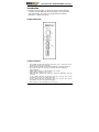
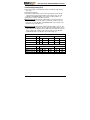
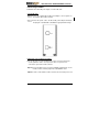
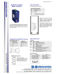
065-1800 series Hardened Media Converter
Preface
This hardened media converter provides an affordable solution for rugged
and outdoor environments, transportation roadside cabinets, industrial
floor operations, multi-tenant dwellings, or Fiber To The Home (FTTH)
applications. It is the media converter of choice for harsh environments
with space constraints. It is capable of operating at temperature extremes
of -40° F to 165° F (-40° C to +74° C).
Plug-and-Play Solution:
The Signamax 065-1800 series hardened media converter is a plug-andplay media converter with a compact case size. There is no complicated
software set up required.
This manual describes how to install and use the Signamax 065-1800 series
hardened media converters with the Link Fault Signaling (LFS) function.
The converters introduced here provide one channel of media conversion
between 10/100BaseT/TX and 100BaseFX connections.
These converters fully comply with IEEE802.3 10BaseT and IEEE802.3u
100BaseTX/FX standards.
In this manual, you will find:
Product overview
Features of the 065-1800 series media converters
llustrative LED functions
Installation instructions
Specifications
User’s Manual
1
065-1800 series Hardened Media Converter
Table of Contents
PREFACE ....................................................................................... 1
TABLE OF CONTENTS ..................................................................... 2
INTRODUCTION ............................................................................... 3
PRODUCT OVERVIEW................................................................. 3
PRODUCT FEATURES ................................................................. 3
PACKING LIST ........................................................................... 4
ONE-CHANNEL MEDIA CONVERTER................................................. 5
PORTS...................................................................................... 5
PORT SETTINGS ........................................................................ 5
FRONT PANEL & LEDS .............................................................. 6
LINK-FAULT-PASS-THROUGH ..................................................... 7
INSTALLATION ................................................................................ 8
SELECTING A SITE FOR THE EQUIPMENT ..................................... 8
D N RAIL MOUNTING ................................................................. 8
CONNECTING TO POWER ........................................................... 9
SPECIFICATIONS ........................................................................... 11
2
User’s Manual
065-1800 series Hardened Media Converter
Introduction
The media converter provides one channel for media conversion between
10/100BaseTX and 100BaseFX with the link-fault-pass-through function.
This hardened fiber optic solution is perfectly fitted in the industrial
applications or rugged environment.
Product Overview
Product Features
Meets NEMA TS1/TS2 Environmental requirements such as temperature, shock,
and vibration for traffic control equipment
Meets EC61000-6-2 EMC Generic Standard Immunity for industrial environment
One-channel media conversion between 10/100BaseT/TX and 100BaseFX
Fiber media allows:
Multimode fiber using SC, ST, VF-45, MT-RJ or LC connector
Singlemode fiber using SC or ST connector
WDM single-fiber (bi-directional) transceiver: Singlemode WDM fiber using SC
connector:
A type: WDM single-fiber (bi-direction) transceiver transmits with 1310nm
wavelength and receives with 1550nm wavelength
B type: WDM single-fiber (bi-direction) transceiver transmits with 1550nm
wavelength and receives with 1310nm wavelength
Auto negotiation of speed and duplex mode on TX port
User’s Manual
3
065-1800 series Hardened Media Converter
Auto MDIX on TX port
One DIP switch for configuring Link Fault Signaling (LFS), fixed speed, full/half
duplex, and link down alarm
Store-and-forward mechanism
Non-blocking full wire-speed forwarding rate
Supports broadcast storm filtering
Back-pressure & IEEE802.3x compliant flow control
Alarms for power and port link down failure by relay output
Redundant 1.5 A / 24 V DC Terminal Block power inputs; models
available with a 3A / 12 V DC jack and a factory-provided 100-240 V AC
external power supply
Supports D N-rail or panel mounting installation
Front panel status LEDs
Packing List
When you unpack this product’s package, you will find the items listed below.
Please inspect the contents, and report any apparent damage or missing
items immediately to our authorized reseller.
The Signamax 065-1800 series Hardened Media Converter
User’s Manual on CD-ROM
Signamax 065-1800 series Hardened Media Converter Quick Installation Guide
AC to DC Power Adaptor and Power Cable (optional 12 V DC powered models only)
4
User’s Manual
065-1800 series Hardened Media Converter
One-Channel Media Converter
Ports
The Signamax 065-1800 series Hardened Media Converter provides one TX
port and one FX port. For the FX port, it provides options of:
Multimode fiber using SC, ST, VF-45, MT-RJ or LC connector, or
Singlemode fiber using SC or ST connector, or
WDM fiber using single SC connector
For the TX port, it uses an RJ-45 connector, auto-MDIX, and autonegotiates 10/100 Mbps speed and full-duplex or half-duplex modes.
Port Settings
Port settings are made easily by means of a DIP (Dual Inline Package)
switch at the front panel of the harden media converter.
Default DIP switch settings:
1
2 3 4 5 6
1
0
DIP switch
There are six pins on the DIP switch for port settings. Refer to the table below for more
details.
DIP switch No. 0
1
1
Disable Link Fault Signaling
2
Enable auto-negotiation for TX Enable forced mode for TX
port
port
Enable Link Fault Signaling
3
TX port forced to 100 Mbps
TX port forced to 10 Mbps
4
TX port forced to full duplex
mode
TX port forced to half duplex
mode
5
FX port forced to full duplex
mode
FX port forced to half duplex
mode
6
Disable link down alarm
Enable link down alarm
First, disconnect the converter from the power. Then toggle Pin 2 of the DIP switch to
position 1 to enable the forced mode for TX port.
<NOTE> Pin 2 must be toggled to position 1 prior to manually setting speed and
duplex mode.
Toggle Pin 3 to position 0 to force the TX port to the speed of 100 Mbps, or toggle Pin
3 to position 1 for 10 Mbps speed.
Toggle Pin 4 to position 0 to force the TX port to full duplex mode, or toggle Pin 4 to
position 1 for half duplex mode.
Toggle Pin 5 to position 0 to force the FX port to full duplex mode, or toggle Pin 5 to
position 1 for half duplex mode.
Toggle Pin 1 to position 0 to disable Link Fault Signaling (LFS).
User’s Manual
5
065-1800 series Hardened Media Converter
Toggle Pin 6 to position 0 to disable the link down alarm.
Reconnect the converter to the power supply. The new setting(s) will then take effect.
Front Panel & LEDs
LED Indicators
The LED indicators give you instant feedback on the status of the converter:
LEDs
State
Indication
FAULT
Steady
Power or ports function abnormally
Off
Power and ports function normally
PWR1
PWR2
Steady
Off
Power on
PWR stands for POWER
Power off
100 (Mbps)
Steady
Connection speed is 100 Mbps
Off
Connection speed is 10 Mbps
LFS
LNK/ACT
Steady Link Fault Signaling function enabled
Off
Link Fault Signaling function
disabled
Steady
A valid network connection
established
Flashing
Transmitting or receiving data
Off
Neither valid network connection
established nor
transmitting/receiving data.
Steady
Connection in full duplex mode
LNK stands for LINK
ACT stands for ACTIVITY
FDX/COL
FDX stands for FULL-DUPLEX
Flashing
Collision occurred
COL stands for COLLISION
Off
6
Connection in half-duplex mode
User’s Manual
065-1800 series Hardened Media Converter
Link Fault Signaling (LFS)
Connect the FX ports of two Media Converters, A and B, through the fiber
optic cable.
Link Fault of the FX port:
A Link Fault condition will be sensed on the TX port whenever the media
converter detects a Link Fault condition on the FX port. Thus, the 100,
LNK/ACT, and FDX/COL LEDs of the media converter would be off.
Link Fault of the TX port of Media Converter A:
Media Converter A: A Link Fault condition will be sensed on the FX port
whenever the media converter detects a Link Fault condition on the TX
port. Thus, the 100, LNK/ACT, and FDX/COL LEDs of the TX port of the
Media Converter A would be off.
Media Converter B: A Link Fault condition indication will be sent to the FX
port of the Media Converter B. Then, a Link Fault condition will be sensed
on the TX port of the Media Converter B whenever the Media Converter B
detects a Link Fault condition on the FX port. Thus, the 100, LNK/ACT,
and FDX/COL LEDs of the Media Converter B would be off.
Link Fault on the FX port
TX Port
FX Port
LEDs
PWR
100
LNK/ACT
FDX/COL
LNK/ACT
FDX/COL
Media Converter A
ON
OFF
OFF
OFF
OFF
OFF
Media Converter B
ON
OFF
OFF
OFF
OFF
OFF
Link Fault on the TX port of Media Converter A
TX Port
FX Port
LEDs
PWR
100
LNK/ACT
FDX/COL
Media Converter A
ON
OFF
OFF
OFF
ON
ON
Media Converter B
ON
OFF
OFF
OFF
OFF
OFF
User’s Manual
LNK/ACT
FDX/COL
7
065-1800 series Hardened Media Converter
Installation
This chapter gives step-by-step installation instructions for the Converter.
Selecting a Site for the Equipment
As with any electric device, you should place the equipment where it will not
be subjected to extreme temperatures, humidity, or electromagnetic
interference. Specifically, the site you select should meet the following
requirements:
The ambient temperature should be between -40° to 165° Fahrenheit (-40° to +74°
Celsius).
The relative humidity should be less than 95 percent, non-condensing.
Surrounding electrical devices should not exceed the electromagnetic field (RFC)
standards for IEC 801-3, Level 2 (3V/M) field strength.
Make sure that the equipment receives adequate ventilation. Do not block the
ventilation holes of the equipment.
The power outlet should be within 6 feet (1.8 meters) of the product.
DIN Rail Mounting
Fix the DIN rail attachment plate to the back panel of the media converter.
Installation: Place the media converter on the DIN rail from above using the
slot. Push the front of the media converter toward the mounting surface
until it audibly snaps into place.
Removal: Pull out the lower edge and then remove the media converter from
the DIN rail.
8
User’s Manual
065-1800 series Hardened Media Converter
Connecting to Power
Redundant 1.5 A 24 V DC power inputs or 3 A 12 V DC Jack:
3 A 12 V DC Jack
Step 1: Connect the supplied AC to DC power adapter to the receptacle on
the topside of the media converter.
Step 2: Connect the power cord to the AC to DC power adapter and attach
the plug into a standard AC outlet with the appropriate AC voltage.
Redundant 1.5 A 24 V DC Power Inputs
There are two pairs of 1.5 A 24 V DC power source connectors that can be
used to power this device. You only need to have one power source
connected to operate the media converter.
Step 1: Connect the DC power cord to the pluggable terminal block on the
media converter, and then plug it into a standard DC outlet.
Step 2: In order to shut down the media converter, disconnect the power cord.
User’s Manual
9
065-1800 series Hardened Media Converter
Alarms for Power and Port Failure
Step 1: There are two pins on the terminal block are used for power failure
detection. It provides the normally closed output when the power
source is active. Use this as a dry contact application to send a
signal for power failure detection.
Terminal Assignment
PWR 1
GND
PWR 2
GND
Power Input 1 (+10 ~ +48 V DC)
Power Ground
Power Input 2 (+10 ~ +48 V DC)
Power Ground
Earth Ground
1. The relay opens if PWR 1 or PWR 2 fails
2. The relay opens if a Link Fault is detected
(if Link Fault Signaling has been Enabled)
Special note:
The relay output is normal open position when there is no power to the
media converter. Please do not connect any power source to this
terminal to prevent the shortage to your power supply.
10
User’s Manual
065-1800 series Hardened Media Converter
Specifications
Applicable Standards
IEEE 802.3 10BaseT
IEEE 802.3u 100BaseTX & 100BaseFX
Fixed Ports
1 TX port, 1 FX port
Speed
10BaseT
10/20Mbps for half/full-duplex
100BaseTX/FX
100/200Mbps for half/full-duplex
Switching Method
Store-and-Forward
Forwarding rate
14,880/148,800pps for 10/100 Mbps
Cable
10BaseT
100BaseTX
100BaseFX
LED Indicators
2-pair UTP/STP Cat. 3, 4, 5 up to 100m
2-pair UTP/STP Cat. 5 up to 100m
MMF (50 or 62.5µm), SMF (9 or 10µm)
Per Unit- (4 LEDs):
PWR1, PWR2, FAULT, LFP
Per Port-
Dimensions
TX (3 LEDs): LNK/ACT, FDX/COL, 100
FX (2 LEDs): LNK/ACT, FDX/COL
W50 × D110 x H136 mm
Weight
0.6 Kg
Power
DC Jack: 3A 12VDC, External AC/DC
required
Terminal Block: 1.5A 24VDC, 10-48VDC
Power Consumption
4.8W Max.
Operating Temperature
-40°C ~ 74°C
Storage Temperature
-45°C ~ 93°C
Humidity
10 ~ 95%, non-condensing
Safety
UL 60950, EN60950, EC 60950,
IEC 61000-6-2
Emissions
FCC Part 15, Class A
CE: EN55022 (CISR22 Class A)
EN55024 (CISPR24 Class A)
Standards
ESD Standard (IEC 61000-4-2)
Radiated FRI Standards (IEC 61000-4-3)
Burst Standards (IEC 61000-4-4)
Surge Standards (IEC 61000-4-5)
Induced RFI Standards (IEC 61000-4-6)
Magnetic Field Standards (IEC 61000-4-8)
Voltage Dips Standards (IEC 61000-4-11)
User’s Manual
11
065-1800 series Hardened Media Converter
Environmental Test Compliance:
Vibration Resistance (IEC 60068-2-6)
Shock (IEC 60068-2-27)
Free Fall (IEC 60068-2-32)
NEMA TS1/2 Environmental requirements for traffic control equipment
12
User’s Manual