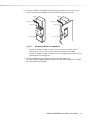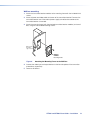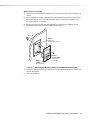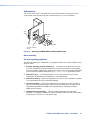
1
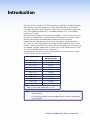
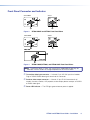
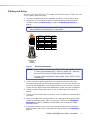
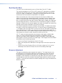
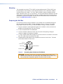
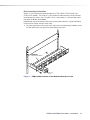
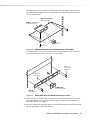
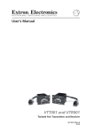
User Guide
Twisted Pair
VTT001 and VTR001
Twisted Pair Transmitter and Receiver
68-760-01 Rev. I
11 12
Safety Instructions
Safety Instructions • English
WARNING: This symbol,
, when used on the product, is intended
to alert the user of the presence of uninsulated dangerous voltage
within the product’s enclosure that may present a risk of electric
shock.
ATTENTION: This symbol,
, when used on the product, is intended to alert
the user of important operating and maintenance (servicing) instructions in
the literature provided with the equipment.
For information on safety guidelines, regulatory compliances, EMI/EMF
compatibility, accessibility, and related topics, see the Extron Safety and
Regulatory Compliance Guide, part number 68-290-01, on the Extron
website, www.extron.com.
Instructions de sécurité • Français
avertissement: Ce pictogramme,
, lorsqu’il est utilisé sur le produit,
signale à l’utilisateur la présence à l’intérieur du boîtier du produit d’une
tension électrique dangereuse susceptible de provoquer un choc
électrique.
attention: Ce pictogramme,
, lorsqu’il est utilisé sur le produit, signale
à l’utilisateur des instructions d’utilisation ou de maintenance importantes
qui se trouvent dans la documentation fournie avec le matériel.
Chinese Simplified(简体中文)
警告:
产品上的这个标志意在警告用户该产品机壳内有暴露的危险
电压,有触电危险。
注 意:
产 品 上 的 这个 标 志 意 在 提 示用 户设 备 随 附 的 用 户手 册 中 有
重要的操作和维护(维修)说明。
关于我们产品的安全指南、遵循的规范、EMI/EMF 的兼容性、无障碍
使用的特性等相关内容,敬请访问 Extron 网站 www.extron.com,参见 Extron
安全规范指南,产品编号 68-290-01。
Chinese Traditional(繁體中文)
警告:
若產品上使用此符號,是為了提醒使用者,產品機殼內存在著
可能會導致觸電之風險的未絕緣危險電壓。
注意
若產品上使用此符號,是為了提醒使用者。
有關安全性指導方針、法規遵守、EMI/EMF 相容性、存取範圍和相關主題的詳細
資訊,請瀏覽 Extron 網站:www.extron.com,然後參閱《Extron 安全
性與法規遵守手冊》,準則編號 68-290-01。
Pour en savoir plus sur les règles de sécurité, la conformité à la
réglementation, la compatibilité EMI/EMF, l’accessibilité, et autres sujets
connexes, lisez les informations de sécurité et de conformité Extron,
réf. 68-290-01, sur le site Extron, www.extron.fr.
Japanese
警告: この記号
が製品上に表示されている場合は、筐体内に絶縁されて
いない高電圧が流れ、感電の危険があることを示しています。
Sicherheitsanweisungen • Deutsch
warnung: Dieses Symbol
auf dem Produkt soll den Benutzer
darauf aufmerksam machen, dass im Inneren des Gehäuses dieses
Produktes gefährliche Spannungen herrschen, die nicht isoliert sind
und die einen elektrischen Schlag verursachen können.
Vorsicht: Dieses Symbol
auf dem Produkt soll dem Benutzer in der im
Lieferumfang enthaltenen Dokumentation besonders wichtige Hinweise
zur Bedienung und Wartung (Instandhaltung) geben.
Weitere Informationen über die Sicherheitsrichtlinien, Produkthandhabung,
EMI/EMF-Kompatibilität, Zugänglichkeit und verwandte Themen finden Sie
in den Extron-Richtlinien für Sicherheit und Handhabung (Artikelnummer 68290-01) auf der Extron-Website, www.extron.de.
Instrucciones de seguridad • Español
ADVERTENCIA: Este símbolo,
, cuando se utiliza en el producto, avisa al
usuario de la presencia de voltaje peligroso sin aislar dentro del producto, lo que
puede representar un riesgo de descarga eléctrica.
ATENCIÓN: Este símbolo,
, cuando se utiliza en el producto, avisa
al usuario de la presencia de importantes instrucciones de uso y
mantenimiento recogidas en la documentación proporcionada con el
equipo.
Para obtener información sobre directrices de seguridad, cumplimiento
de normativas, compatibilidad electromagnética, accesibilidad y temas
relacionados, consulte la Guía de cumplimiento de normativas y seguridad
de Extron, referencia 68-290-01, en el sitio Web de Extron, www.
extron.es.
注意: この記号
が製品上に表示されている場合は、本機の取扱説明書に
記載されている重要な操作と保守(整備)の指示についてユーザーの
注意を喚起するものです。
安全上のご注意、法規厳守、EMI/EMF適合性、その他の関連項目に
ついては、エクストロンのウェブサイトwww.extron.comより
『 Extron Safety and Regulatory Compliance Guide 』(P/N 68-290-01) をご覧ください。
Korean
경고: 이 기호
, 가 제품에 사용될 경우, 제품의 인클로저 내에 있는 접지되지
않은 위험한 전류로 인해 사용자가 감전될 위험이 있음을 경고합니다.
주의:
이 기호
, 가 제품에 사용될 경우, 장비와 함께 제공된 책자에 나와
있는 주요 운영 및 유지보수(정비) 지침을 경고합니다.
안전 가이드라인, 규제 준수, EMI/EMF 호환성, 접근성, 그리고 관련
항목에 대한 자세한 내용은 Extron 웹 사이트(www.extron.com)의
Extron 안전 및 규제 준수 안내서, 68-290-01 조항을 참조하십시오.
FCC Class A Notice
This equipment has been tested and found to comply with the limits for a Class A digital
device, pursuant to part 15 of the FCC rules. The Class A limits provide reasonable
protection against harmful interference when the equipment is operated in a commercial
environment. This equipment generates, uses, and can radiate radio frequency energy and,
if not installed and used in accordance with the instruction manual, may cause harmful
interference to radio communications. Operation of this equipment in a residential area is
likely to cause interference; the user must correct the interference at his own expense.
NOTE: This unit was tested with shielded I/O cables on the peripheral devices. Shielded
cables must be used to ensure compliance with FCC emissions limits.
For more information on safety guidelines, regulatory compliances,
EMI/EMF compatibility, accessibility, and related topics, see the “Extron Safety and
Regulatory Compliance Guide” on the Extron website.
Specifications Availability
Product specifications are available on the Extron website, www.extron.com.
Conventions Used in this Guide
Notifications
The following notifications are used in this guide:
WARNING: A warning indicates a situation that has the potential to result in death or
severe injury.
CAUTION: A caution indicates a situation that may result in minor injury.
NOTE: A note draws attention to important information.
Copyright
© 2012 Extron Electronics. All rights reserved.
Trademarks
All trademarks mentioned in this guide are the properties of their respective owners.
Contents
Introduction.................................................... 1
Reference Information................................ 17
Features.............................................................. 2
Parts List........................................................... 17
VTT001 MAAP and VTR001 MAAP .............. 17
VTT001 and VTR001 Tabletop....................... 17
VTR001 AAP................................................. 17
Included Parts............................................... 17
Skew-Free™ AV UTP Cables......................... 18
Other Accessories......................................... 18
Installation...................................................... 3
Rear Panel Connectors........................................ 3
Front Panel Connector and Indicator................... 6
Cabling and Setup............................................... 7
Compatibilty with Other Extron Products......... 8
Cable Testing................................................... 8
Equalizing Pair Skew....................................... 9
Sharpness Adjustment.................................... 9
Mounting....................................................... 10
Preparing the Wall Box.................................. 10
VTT001 and VTR001 User Guide • Contents
v
Introduction
The Extron VTT001 Twisted Pair (TP) Transmitter Series and VTR001 Twisted Pair Receiver
Series provide a system for sending VGA, RGBHV, ansd RGBS signals up to 500 feet
(150 meters) over Extron Skew-Free AV UTP cable. They can also send these signals over
CAT 5/5e/6 shielded twisted pair (STP), unshielded twisted pair (UTP), or foil shielded
twisted pair (FTP) cable.
Both transmitter and receiver have remote power capability. For transmission distances up
to 300 feet, the applied power is required at either the transmitter or the receiver. Greater
distances require power to be applied locally to both transmitter and receiver.
Depending on the model, both transmitter and receiver modules may be mounted in a
wall, a rack, or in other Extron products that accept a double-sized MAAP panel (such as
CPM101, CPM200, and CPM112R), or Extron AAP mounting products; or they may be set
on a tabletop. The MAAP model comes in a black finish; the AAP model comes in a white
finish; and the tabletop model comes in a black finish.
The following table specifies the maximum recommended transmission distances for the
VTT001/VTR001 pair with a signal at 60 Hz.
Video Resolution
Recommended
Maximum Range
640 x 480
500 feet
800 x 600
400 feet
1024 x 768*
300 feet
1280 x 960*
200 feet
1280 x 1024*
200 feet
1360 x 765
200 feet
1365 x 768
200 feet
1366 x 768
200 feet
1440 x 900
200 feet
1440 x 1050
200 feet
1600 x 1200*
150 feet
NOTE: Video resolutions marked with an asterisk (*)
have the same range specification at 75 Hz.
NOTES: • Extron recommends using at least 50 feet of TP cable between the transmitter
and the receiver.
• It is possible to exceed the recommended distances. However, image quality
may be reduced.
VTT001 and VTR001 User Guide • Introduction
1
Features
•
Video sharpness control — Optimizes the video image for different cable lengths
between transmitter and receiver.
•
Removable faceplate — The module faceplate may be removed for tabletop use or
attachment to an equipment rack.
•
Compatibility — The VTR001 receiver also functions as the receiver for output from the
Extron IN1404XT video scaler, Extron TP T 15HD A, TP T 15HD AV, TP T BNC,
TP T 15HD 45, TPX 88, TPX 88 A, and TP T BNC DA4.
•
Remote power capability — Both transmitter and receiver can be powered remotely
when cable runs are 300 feet or less.
VTT001 and VTR001 User Guide • Introduction
2
Installation
The Installation section describes:
•
Rear Panel Connectors
•
Front Panel Connector and Indicator
•
Cabling and Setup
Rear Panel Connectors
VTT001 MAAP
VTR001-VTT001
VTT001
TX Layout
Panel
2
TX
1a
Figure 1.
9VDC-12VDC
500mA
9VDC-12VDC
500mA
1a
2a
2b
VTT001 MAAP and VTT001 Rear Panel Views
NOTE: The VTT001 MAAP and VTT001 models differ in how they are mounted (see
Mounting on page 10).
VTR001 MAAP
VTR001
RX
RX
1b
9VDC-12VDC
500mA
9VDC-12VDC
500mA
1b
2a
2b
VTR001 AAP
9VDC-12VDC
500mA
RX
1b
Figure 2.
2a
VTR001 MAAP, VTR001, and VTR001 AAP Rear Panel Views
NOTE: The VTR001 MAAP, VTR001 AAP, and VTR001 models differ in how they are
mounted (see Mounting on page 10).
VTT001 and VTR001 User Guide • Installation
3
Ä Transmitter output connector — A female RJ-45 connector on a 3 inch pigtail for the
VTT001 MAAP, or within the VTT001 model. Plug the twisted pair cable going to the
receiver into this connector.
CAUTION: Do not connect the transmitter to a computer data or
telecommunications network.
Å Receiver input connector — A female RJ-45 connector on a 3 inch pigtail for the
VTR001 MAAP and VTR001 AAP models, or within the VTR001 model. Plug the twisted
pair cable coming from the transmitter into this connector.
CAUTION: Do not connect the receiver to a computer data or telecommunications
network.
Ç Captive screw input power connector — Connect the included
12 VDC external power supply to the 2-pole female direct insertion
captive screw connector. The VTT001 MAAP, VTR001 AAP, and the
VTR001 MAAP have this captive screw connector.
Power Connection
Power
12VDC
–
9VDC-12VDC
500mA
+
TX
A
A
Power Supply
Output cord
SECTION A–A
CAUTIONS: • Always use a power supply supplied by or specified by Extron. Use
of an unauthorized power supply voids all regulatory compliance
certification and may cause damage to the supply and the end
product.
• Unless otherwise stated, the AC/DC adapters are not suitable for
use in air handling spaces or in wall cavities. The power supply is
to be located within the same vicinity as the Extron AV processing
equipment in an ordinary location, Pollution Degree 2, secured to the
equipment rack within the dedicated closet, podium or desk.
• The installation must always be in accordance with the applicable
provisions of National Electrical Code ANSI/NFPA 70, article 75
and the Canadian Electrical Code part 1, section 16. The power
supply shall not be permanently fixed to building structure or similar
structure.
To verify correct polarity before connection, check the power supply no load output with
a voltmeter.
WARNING: May result in serious injury.
The two power supply leads must be kept separated while the power supply is
plugged into an electrical outlet. Remove power before wiring.
VTT001 and VTR001 User Guide • Installation
4
CAUTION: Do not tin the stripped power supply leads before inserting them into
the captive screw connector. Tinned leads are not as securely attached as
untinned leads and could slip out.
NOTE: Both transmitter and receiver have remote power capability. For
transmission distances up to 300 feet, the power is required only at either the
transmitter orwiring.eps
the receiver. Greater distances will require power to be applied to
Power Connector
both transmitter and receiver.
É Power input jack — Connect the included 12 VDC external power supply to this
female jack. The VTT001 and the VTR001 use this power input connector (see the note,
cautions, and warning for Ç above).
The male power plug that connects to this input jack is shown below.
Power plug
Tip (+)
Sleeve
Tip (+)
Sleeve
VTT001 and VTR001 User Guide • Installation
5
VTR001-VTT001 Panel Layout 2
Front Panel Connector and Indicator
VTT001 MAAP
VTT001
3
3
MAAP
1
1
Figure 3.
VTT001 MAAP and VTT001 Front Panel Views
VTR001
VTR001 MAAP
3
3
MAAP
2
2
VTR001 AAP
3
OUTPUT
VTR001 AAP
2
Figure 4.
VTR001 MAAP, VTR001, and VTR001 AAP Front Panel Views
NOTE: The VTR001 MAAP, VTR001 AAP, and VTR001 models differ in how they are
mounted. The AAP version has a larger faceplate than the VTR001 MAAP.
a Transmitter video input connector — A female 15-pin HD VGA input for all models.
Plug an RGBHV/RGBS video signal source into this connector.
b Receiver video output connector — A female 15-pin HD VGA connector for all
models. Connect a monitor, LCD projector, or other display device to output an RGBHV
or RGBS video signal.
c Power LED indicator — The LED lights green whenever power is applied.
VTT001 and VTR001 User Guide • Installation
6
Cabling and Setup
To install the VTT001 MAAP and VTT001 models and the VTR001 MAAP, VTR001 AAP, and
VTR001 models, follow these steps:
1. Turn all of the equipment off and, if applicable, disconnect it from the power source.
2. Connect the RJ-45 connectors of the transmitter and receiver to either end of the
twisted pair cable (see Cable Testing on page 8 and Equalizing Pair Skew on
page 9).
NOTE: RJ-45 termination must comply with the TIA/EIA T568A or TIA/EIA T568B
wiring standards for all connections, as shown below.
Pins:
12345678
Pin
1&2
TIA/EIA T568A
Wire color
RGB Video
Signal
TIA/EIA T568B
Wire color
1
White-green
White-orange
Red/V. sync +
2
Green
Orange
Red/V. sync -
3
White-orange
White-green
Power
4
Blue
Blue
Green +
5
White-blue
White-blue
Green -
6
Orange
Green
Power
7
White-brown
White-brown
Blue/H. sync +
8
Brown
Brown
Blue/H. sync -
7&8
3&6 4&5
Twisted Pairs (4)
RJ-45
Connector
Figure 5.
RJ-45 Pin Terminations
NOTES: • For best results, use Extron Skew-Free AV UTP cable, available in bulk or
in various pre-terminated lengths. If necessary, regular CAT 5 cable may
be used. CAT 5e and CAT 6 cables are not recommended.
• If you are using Enhanced Skew-Free AV cable, use the TIA/EIA T-568-A
standard only.
3. Connect the external power supply to the transmitter, the receiver, or both. Both
transmitter and receiver have remote power capability. For transmission distances up
to 300 feet, the applied power is only required at either the transmitter or the receiver.
Greater distances require power to be applied locally to both transmitter and receiver.
4. Connect an output display device to the 15-pin HD video output connector of the
receiver.
5. Connect a RGBHV/RGBS video source to the 15-pin HD video input connector of the
transmitter.
6. Power up the video input and output devices, then apply power to the power supply
and test for the display output. Adjust the sharpness, if necessary (see Sharpness
Adjustment on page 9). If a problem is encountered, check all connections before
proceeding further.
7. If the previous display test was successful, power off and disconnect all equipment,
detach all cables, and install the mountable transmitter or receiver (see Mounting on
page 10).
VTT001 and VTR001 User Guide • Installation
7
NOTE: If the transmitter or receiver is to be wall mounted and the power supply will be
inaccessible, power must be applied to the power supply before final mounting.
Compatibilty with Other Extron Products
The VTT001 series and VTR001 series products can communicate with other Extron
products. The following tables indicate how the products interact.
VTR001 series
VTT001 series
TP T 15HD A
TP T 15HD AV
TP T BNC
TP T BNC DA4
TP T AV
TP T 460
A
A
A
A
B
A
TP R BNC AV
TP R BNC A
TP R AV
TP R 15HD A
A
A
B
A
TP T 468
A
IN1404XT
TP T 15HD 45
A
A
A = RGB video only
B = incompatible
NOTE: The VTT001 series and VTR001 series will not power the compatible Extron
products remotely.
Cable Testing
To ensure proper cable termination, each transmission cable system that uses CAT 5e or
CAT 6 cable should be tested (Extron Skew-Free AV UTP cable does not need to be tested).
Testing the cable from the RJ-45 connections at the transmitter and receiver gives the most
accurate indications of cable problems.
There are two varieties of cable runs: simple runs, in which a single cable is terminated
only at the transmitter and receiver; and complex runs, which can include patch bays and
multiple terminations and lengths of cable. In either case, the entire cabling system should
be tested.
A complete test measures cable length and tests the wire map, attenuation, NEXT, PSNEXT,
ELFEXT, PSELFEXT, return loss, ACR and PSACR. All of these tests are critical for digital
data transfer. While all of these tests are important indicators of the quality of the cable
termination, the most critical testing parameters for video transfer are wire map (T568A or
T568B termination) and pair length measurements. The largest concern is equalization of
skew between cable pairs. Cable systems of 300 feet or less should exhibit no transmission
problems if they pass at least CAT 5e or preferably CAT 6-D5 channel certification testing.
The Microtest® OMNI SCANNER™ 2 performs comprehensive certification testing to the
proposed CAT 6 standards. Other manufacturers also make testing equipment. The tests
include advanced diagnostics for troubleshooting the cause and location of many cable and
termination problems. For simple installation testing, the Microtest MICRO SCANNER PRO
tests wire map and cable length, including individual cable pair length.
VTT001 and VTR001 User Guide • Installation
8
Equalizing Pair Skew
Pair skew issues are eliminated when you use Extron Skew-Free AV UTP cables.
The manufacturing process for CAT 5e or CAT 6 network UTP cable leads to a condition
called pair skew. For best results, pair skew needs to be equalized when using the CAT
5e or CAT 6 cable in AV applications. The design of the Extron Skew-Free AV UTP cable
minimizes pair skew to the point that equalization is not required.
Skew exists between pairs when the physical length of one wire pair is different from
another. As the transmission cable length increases, the amount of skew increases. Skew
affects the displayed image when the differential length between wire pairs exceeds two
feet, causing the timing of the red, green, and blue video signals to appear out of alignment
(horizontal registration errors). A white vertical line on a black field can appear as individual
red, green, and blue lines that are close together; the signal transmitted on the shortest wire
pair leads the other colors and appears to the left on the display.
UTP cable test equipment measures and reports wire pair length. The report on the various
pair lengths can be used in equalizing pair skew. The nominal velocity of propagation (NVP
— the speed at which the signal travels on the transmission line, measured as a percentage
of the speed of light) of TP cable is very close to that of conventional coaxial cable. The
difference in NVP means that an additional length of coaxial cable equal to the length of pair
skew, placed on the receiver’s output, equalizes the effects of pair skew.
CAT 5 TP cable can lead to registration errors between the red, green, and blue video
signals. Pair skew can be measured with test equipment or identified by viewing a
crosshatch test pattern closely to determine if either the red, green, or blue video image
leads (appears to the left of) the other two video images. These images can be minimized or
eliminated by one of the following methods:
•
Switch to the Extron Enhanced Skew-Free AV UTP cable.
•
Add a skew compensation cable equal to the length of pair skew to the output of the
receiver.
•
Install an Extron Skew Equalizer, SEQ 100 15HD (part number: 60-676-01), on the
video output of the receiver and adjust the skew for the leading video image.
Sharpness Adjustment
The longer the cable being used, the greater the signal loss. The image sharpness may
be enhanced by turning a peaking adjustment screw located on the top of the receiver.
Increased peaking can compensate for detail (mid- and high-frequency) loss from low
bandwidth system components or capacitance in long cables. Adjust this control using the
included adjustment tool while viewing the displayed image to obtain the optimum picture
sharpness. Turning the control clockwise increases peaking and turning it counterclockwise
decreases peaking.
S
H
A
R
P
Sharpness
UT
TP
OU
VT
R0
01
MA
AP
VTT001 and VTR001 User Guide • Installation
9
Mounting
The mountable transmitter (VTT001 MAAP) and mountable receiver (VTR001 MAAP) may
be attached to a wall with either a stud-mounted wall box or with an MR Series modular
mud ring (Extron part number: 70-519-xx). Both installations require the double spaced
MAAP connector frame, such as the CPM101). The transmitter/receiver module can also be
attached to any Extron MAAP device that accepts a double spaced AV connector panel, or
the modules may be rack mounted. The AAP version of the receiver mounts to Extron AAP
frames (see Other Accessories on page 18).
Preparing the Wall Box
For wall and furniture mounting installations, the installation site must be deep enough for
both the wall box and the cables. The box should be at least 2.5 inches (6.4 cm) deep.
Install cables into the wall, furniture, or conduits before installing a wall box or bracket.
1. Place the wall box or mounting bracket against the installation surface, and mark the
guidelines for the opening on the wall or furniture.
2. Cut out the material from the marked area.
3. Insert the wall box or bracket to check the size and fit of the opening. Enlarge or
smooth the edges of the opening if needed.
4. If using a wall box, feed cables through the punch-out holes on the wall box, and secure
Connecting Shields_1-gang.eps
them with cable clamps to provide strain relief.
5. Exposed cable shields (braids or foil) are potential sources of short circuits. Trim back
and insulate shields with heat shrink.
Screw
Braided Shield
Metal Wall Box
Cable Clamp
Installation Cable
Foil Shield
Figure 6.
Grounding Outer Braided and Foil Shields
CAUTION: To prevent short circuits, the outer foil shield can be cut back to the
point where the cable exits the cable clamp. Both braided and foil shields should
be connected to an equipment ground at the other end of the cable.
VTT001 and VTR001 User Guide • Installation
10
1-gang wall box.eps
6. Insert the wall box or wall bracket into the opening, and attach it to the wall, stud, or
furniture, leaving the front edge flush with the outer wall or furniture surface.
Wall Stud
Installation Cable
Wall Stud
Installation Cable
Cable Clamp
Cable Clamp
Screws or Nails
Screws or Nails
Figure 7.
Attaching a Wall Box to a Wall Stud
•
To attach a wall box to wood, use four #8 or #10 screws or 10-penny nails. A
minimum of 0.5 inch (1.3 cm) of screw threads must penetrate the wood.
•
To attach a wall box to metal, use four #8 or #10 self-tapping sheet metal screws or
machine bolts with matching nuts.
7. Mount the modules onto a faceplate or frame, then cable and test the
transmitter/receiver modules before fastening it into the wall box or bracket. The cables
are inaccessible after installation.
VTT001 and VTR001 User Guide • Installation
11
Wall box mounting
1. Attach the transmitter/receiver modules to the mounting frame with the included #4-40
screws.
2. Attach all power and video cables to the rear of the transmitter/receiver. Power on the
VTT001 install in wall box.eps
transmitter/receiver now if the external power supply cannot be accessed once the
transmitter/receiver is mounted.
3. Attach the mounting frame (with the attached transmitter/receiver modules) to the wall
box, using the two included mounting screws.
Wall opening
flush with
edge of box
WER
PO
VT
T0
01
M AA
P
T
O
PU
IN
VIDE
VT
T 00
1
MA
AP
Extron
CPM101
Mounting Frame
Figure 8.
Attaching the Mounting Frame to the Wall Box
4. Connect the video input and output devices to the front faceplates of the transmitter
and receiver, respectively.
5. Power on all devices.
VTT001 and VTR001 User Guide • Installation
12
Wall bracket
mounting
VTT001 Wall
Mounting w new Bracket.eps
1. Attach the transmitter/receiver modules to the mounting frame with the included #4‑40
screws.
2. Attach all power and video cables to the rear of the transmitter/receiver. Power on the
transmitter/receiver now if the external power supply cannot be accessed once the
transmitter/receiver is mounted.
3. Attach the mounting frame (with the attached transmitter/receiver modules) to the
mounting bracket using the two included mounting screws.
Backing Clip
Extron
70-163-xx
Wall Mounting Bracket
R
WE
PO
VT
T0
01
MA
AP
UT
INP
VT
Extron
T0
01
MA
AP
Extron
VTT001 MAAP
Twisted Pair
Transmitter
CPM101
Mounting Frame
Figure 9.
Attaching the Mounting Frame to the Wall Mounting Bracket
4. Attach the video input and output devices to the front faceplates of the transmitter and
receiver, respectively.
5. Power on all devices.
VTT001 and VTR001 User Guide • Installation
13
VTT001CM AAP Install.eps
AAP mounting
The VTR001 AAP version is mounted to the Extron AAP panel by inserting the two AAP
studs through the panel mounting holes and attaching the nuts, as shown below.
Cable
Clamp
AAP 102
Cable
2
P 10
AA
UT
EO
VID
P
INP
01
AA
R0
VT
VTR001 AAP
#4-40 Nut w/ Captive
Washer
Figure 10. Attaching a VTR001 AAP to an Extron AAP Frame
Rack mounting
UL rack mounting guidelines
The following Underwriters Laboratories (UL) guidelines pertain to the safe installation of the
device in a rack.
1. Elevated operating ambient temperature — If installed in a closed or multi-unit rack
assembly, the operating ambient temperature of the rack environment may be greater
than room ambient temperature. Therefore, install the unit in an environment compatible
with the maximum ambient temperature (Tma = +122 °F, +50 °C) specified by Extron.
2. Reduced air flow — Install the equipment in a rack so that the amount of air flow
required for safe operation of the equipment is not compromised.
3. Mechanical loading — Mount the equipment in the rack so that a hazardous condition
is not achieved due to uneven mechanical loading.
4. Circuit overloading — Connect the equipment to the supply circuit and consider the
effect that circuit overloading might have on overcurrent protection and supply wiring.
Appropriate consideration of equipment nameplate ratings should be used when
addressing this concern.
5. Reliable earthing (grounding) — Maintain reliable grounding of rack-mounted
equipment. Pay particular attention to supply connections other than direct connections
to the branch circuit (that is, use of power strips).
VTT001 and VTR001 User Guide • Installation
14
Rack mounting instructions
Various 1U rack space frames accommodate the VTT001 MAAP, VTR001 MAAP, and
VTR001 AAP modules. The CPM133 is a one-third rack width frame that can be mounted
to the IN9080 rack mount shelf. The CPM112R, as shown below, is a full rack width frame
that holds six double sized modules.
Depending on the AV connector frame used, the transmitters/receivers may be mounted to
the rack with or without the rack mount shelf.
1. For mounting without a rack mount shelf, mount the transmitter/receiver modules to the
AV connector frame, then attach the frame directly to the rack.
WER
PO
er
itt
sm
T
CM Tr an
PU
01 ir
IN
O
T0 Pa
VT te d
VIDE
is
Tw
CPM112R
WER
PO
er
itt
sm
T
CM Tr an
PU
01 ir
IN
O
T0 Pa
VT te d
VIDE
is
Tw
AV Connector Frame
WER
PO
er
itt
sm
T
CM Tr an
PU
01 ir
IN
O
T0 Pa
VT te d
VIDE
is
Tw
WER
PO
er
itt
sm
T
CM Tr an
PU
01 ir
IN
O
T0 Pa
VT te d
VIDE
is
Tw
WER
PO
er
itt
sm
T
CM Tr an
PU
01 ir
IN
O
T0 Pa
VT te d
VIDE
is
Tw
WER
PO
er
itt
sm
T
CM Tr an
PU
01 ir
IN
O
T0 Pa
VT te d
VIDE
is
Tw
(4) #4 - 40
Screws
Figure 11. CPM112R AV Connector Frame Mounted Directly to a Rack
VTT001 and VTR001 User Guide • Installation
15
For mounting the VTT001 MAAP or VTR001 MAAP to a rack mount shelf, mount the
transmitter/receiver modules to the AV connector frame, then attach the frame to the
shelf, as shown below.
RSB 129 (60-190-01)
Rack Mount Shelf
CPM133 (60-584-15) or
AV Connector Frame
R
WE
PO
r
tte
mi
ns
UT
CM Tra
01 ir
INP
T0 Pa
EO
VT ed
VID
ist
Tw
(4) #4 - 40
Screws
(4) #6 Screws
Figure 12. CPM133 AV Connector Frame Mounted to a Rack Shelf
For mounting the VTR001 AAP to a rack, mount the AAP modules to the Extron AAP
frame, then attach the frame to the rack, as shown below.
#10-32 Screw/
Nylon Captive
Cap Washer
1
P 30
AA
#4-40 Nut with
Captive Washer
T
AP
INPU
1A
00
VTT
VTR001 AAP
Twisted Pair Transmitter
AAP 301
Architectural Frame
Figure 13. Extron AAP 301 Frame Mounted Directly to a Rack
2. Attach all power and video cables to the rear of the transmitter/receiver. Power on the
transmitter/receiver now if the external power supply cannot be accessed once the
transmitter/receiver is mounted.
3. Attach the video input and output devices to the front faceplates of the transmitter and
receiver, respectively. Power on all devices.
VTT001 and VTR001 User Guide • Installation
16
Reference
Information
Parts List
VTT001 MAAP and VTR001 MAAP
Description
Part Number
VTT001 MAAP wall mount transmitter - black
70-284-11
VTR001 MAAP wall mount receiver - black
70-285-11
NOTE: The MAAP models mount into MAAP (mini AAP) panels.
VTT001 and VTR001 Tabletop
Description
Part Number
VTT001 tabletop transmitter - black
60-581-01
VTR001 tabletop receiver - black
60-582-01
VTR001 AAP
Description
Part Number
VTR001 AAP (white)
70-259-21
NOTE: The VTR001 AAP device can be mounted in the Extron AAP
panels listed under “Other Accessories.”
Included Parts
Description
Part Number
Power supply: universal, 12 VDC, 1.0 A
Sharpness adjustment tool
VTT001 and VTR001 Setup Guide
VTT001 and VTR001 User Guide • Reference Information
17
Skew-Free™ AV UTP Cables
Description
Part Number
UTP23SF-4/1000 1000' bulk (non-plenum)
22-141-03
UTP23SF-4P/1000 1000' bulk (plenum)
22-142-03
UTP23SF-4/12 12' preterm. (non-plenum)
26-569-03
UTP23SF-4/25 25' preterm. (non-plenum)
26-569-04
UTP23SF-4/50 50' preterm. (non-plenum)
26-569-06
NOTE: Other cable lengths are available.
Other Accessories
Description
Part Number
CPM101 MAAP plate, one-gang (black, white)
60-583-11, -21
CPM112R MAAP rack-mount connector panel
60-584-12
CPM133 one-third rack width panel
60-584-15
RSU 129 rack mount shelf
60-190-01
RSB 129 9.5" deep basic rack shelf
60-604-02
AAP 102 frame (black)
60-300-02
AAP 102 frame (white)
60-300-03
AAP 104 frame (black)
60-301-02
AAP 104 frame (white)
60-301-03
AAP 106 frame (black)
60-531-02
AAP 201 frame - half rack width, 1U (black)
60-302-02
AAP 301 frame - full rack width, 1U (black)
60-632-02
AAP 302 frame - full rack width, 1U (black)
60-633-02
VTT001 and VTR001 User Guide • Reference Information
18
Extron Warranty
Extron Electronics warrants this product against defects in materials and workmanship for a period of three years
from the date of purchase. In the event of malfunction during the warranty period attributable directly to faulty
workmanship and/or materials, Extron Electronics will, at its option, repair or replace said products or components,
to whatever extent it shall deem necessary to restore said product to proper operating condition, provided that it is
returned within the warranty period, with proof of purchase and description of malfunction to:
USA, Canada, South America,
and Central America:
Extron Electronics
1001 East Ball Road
Anaheim, CA 92805
U.S.A.
Japan:
Extron Electronics, Japan
Kyodo Building, 16 Ichibancho
Chiyoda-ku, Tokyo 102-0082
Japan
Europe and Africa:
Extron Europe
Hanzeboulevard 10
3825 PH Amersfoort
The Netherlands
China:
Extron China
686 Ronghua Road
Songjiang District
Shanghai 201611
China
Asia:
Extron Asia
135 Joo Seng Road, #04-01
PM Industrial Bldg.
Singapore 368363
Singapore
Middle East:
Extron Middle East
Dubai Airport Free Zone
F12, PO Box 293666
United Arab Emirates, Dubai
This Limited Warranty does not apply if the fault has been caused by misuse, improper handling care, electrical
or mechanical abuse, abnormal operating conditions, or if modifications were made to the product that were not
authorized by Extron.
NOTE: If a product is defective, please call Extron and ask for an Application Engineer to receive an RA (Return
Authorization) number. This will begin the repair process.
USA: 714.491.1500 or 800.633.9876
Asia: 65.6383.4400
Europe:31.33.453.4040
Japan:81.3.3511.7655
Units must be returned insured, with shipping charges prepaid. If not insured, you assume the risk of loss or damage
during shipment. Returned units must include the serial number and a description of the problem, as well as the
name of the person to contact in case there are any questions.
Extron Electronics makes no further warranties either expressed or implied with respect to the product and its quality,
performance, merchantability, or fitness for any particular use. In no event will Extron Electronics be liable for direct,
indirect, or consequential damages resulting from any defect in this product even if Extron Electronics has been
advised of such damage.
Please note that laws vary from state to state and country to country, and that some provisions of this warranty may
not apply to you.
Extron Headquarters
Extron Europe
Extron Asia
Extron Japan
+1.800.633.9876 (Inside USA/Canada Only)
Extron USA - West
Extron USA - East
+1.714.491.1500+1.919.850.1000
+1.714.491.1517 FAX
+1.919.850.1001 FAX
+800.3987.6673
(Inside Europe Only)
+31.33.453.4040
+31.33.453.4050 FAX
800.3987.6673
(Inside Asia Only)
+65.6383.4400
+65.6383.4664 FAX
+81.3.3511.7655
+81.3.3511.7656 FAX
Extron China
+4000. 398766
(Insidse China Only)
+86.21.3760.1568
+86.21.3760.1566 FAX
Extron Middle East
Extron Korea
Extron India
+971.4.2991800
+971.4.2991880 FAX
+82.2.3444.1571
+82.2.3444.1575 FAX
1800.3070.3777
(Inside India Only)
+91.80.3055.3777
+91.80.3055.3737 FAX
© 2012 Extron Electronics All rights reserved. www.extron.com