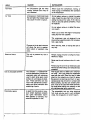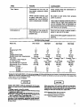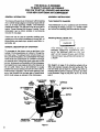
1
SEARS
OWNERS
MANUAL
CRAFTSMAN
AIR COMPRESSOR
MODEL NO.
919.176210
919,176311
919.176320
919.176330
Record In the spaces provided.
(1) The model number which can be
found on the label on the front Of the
air tank saddle.
(2) The code number which can be
found on the ,'oil label on the aide of
the air tank.
(3) The Manufacturers
Number (ASME
Code Compressors only) Is located
on the metal data plate which is
welded onto the side of the air tank,
(This data plate is painted the same
color as the tank.)
(4) The Motor Manufacturers
name
which is located on the motor iabet.
(5) The Motor Mfg. number
- also
!ocawd on the motor label.
Retain these numbers
for future
reference.
IMPORTANT
Read the Safety Guidelines
and All Instructions
Carefully Before Operating
ASSEMBLY
---OPERATION
MAINTENANCE
REPAIR PARTS
Model No ..............
Code NO, =
MfO. No.
Motor Mfg. Name
,
Motor Mfg. No,
Seers,
BI-30-og.1-D
5/85
Roebuck
and Co., Chicago,
IL 60684
U.S.A.
TABLE OF CONTENTS
Page
WARRANTY
.........................................................
SAFETY GUIDELINES
SPECIFICATION
3
................................................
3
CHART ..............................................
5
GENERAL INFORMATION
.............................................
6
GENERAL DESCRIPTION
OF OPERATION ..............................
6
ASSEMBLY
INSTRUCTIONS ...........................................
6
Tools Needed for Assembly .........................................
Attaching Wheels, Handle, Etc.......................................
Grounding Instructions .............................................
Start-Up Procedures ...............................................
OPERATION
6
6
7
.........................................................
7
Control Console ...................................................
Pressure Switch ...................................................
Safety Valve ......................................................
Motor .............................................
Pressure Release Valve ............................................
MAINTENANCE
......................................................
Replacing Air Intake Filter ..........................................
Checking Safety Valve .............................................
Checking and Changing Oil .........................................
Location of Air Compressor .........................................
Draining Water From Air Tank .......................................
Replacing Belt ....................................................
Storage ..........................................................
AIR COMPRESSOR
DIAGRAM .........................................
7
8
: ..............
8
8
8
8
8
8
9
9
9
9
9
10
PARTS LIST, .........................................................
11
ACCESSORIES
13
......................................................
TROUBLESHOOTING
GUIDE ..........................................
HOW TO ORDER REPAIR PARTS ......................................
13
16
FULL ONE YEAR WARRANTY
AIR COMPRESSOR
If this air compressor fails due to a defect in material or workmanship within one year from the date
of purchase, return it to the nearest Sears Service Center/Department throughout the United States
and Sears will repair it, free of charge.
If this air compressor is used for commercial or rental purposes, the warranty will apply for ninety
days from date of purchase,
This warranty gives you specific legal rights and you may also have other rights which vary from
state to state.
Sears, ROebuck and Co,, Sears Tower, Dept. 698/731A, Chicago, IL 60684
SAFETY
GUIDELINES
This manual contains information that is important for you to know and understand.
This information relates to YOUR SAFETY and PREVENTING
EQUIPMENT
PROBLEMS.
To help you recognize this information, we use the following symbols. Please read the manual and
pay attention to those s_ctions.
IMPORTANT
INFORMATION
Information
FOR
PREVENTING
INJURY OR LO$._ O.= LIT--.
for
preventing
damage to equipment
Note
Information that you should pay special attention to.
WARNING
rl
I
'1III
PLEASE READ THE FOLLOWING
_
__
........
_
-
AREA
Indicates
where
a hazard
can oCCur.
_
m,
•
Moving Pa_s
,=
CHART.
_--
....
•
,,
_........
_
..............
HAZARD
SAFEGUARDS
Indicates what can happen if precautions are not observed.
Indicates how to avoid the hazard and what
special protective clothing, equipment, and
precautions will be used.
,, _
,............
__
.......
Loose items, or parts of the bOdy
may get caught and cause sadDUe injury or damage,
Never operate the compressor with the console removed.
Keep small children, your hands, and all
items away from the flywheel and belt.
Unit cycles automatically when
power is ON. During service or
repair activities, this automatic
cycling may cause a hazard.
_
_
,,
Always unplug the unit before attempting repair or maintenance of the compressor. Also,
make sure the pressure is released from the
compressor and air tank.
,
,
,,,
,,
,,, ,,,,,,,
HAZARD
AREA
SAFEGUARDS
,,,i
i ii
Hot Parts
Air compressors get hOt when
running. Serious burns may result if touched.
Air Tank
Air pressure or mechanical loads
that are higher than design loads
may cause the tank to rupture.
.....................
ii ,i
Never touch the compressor, tubing, or
motor during or immediately after operation
of the compressor.
DO not adjust, remove, or defeat the safety
valve. Check the valve from time to time by
pulling the ring on the valve. If the valve is
stuck or does not operate smoothly, it must
be replaced.
Do not adjust, remove, or defeat the pressure switch.
Never use a motor with higher horsepower
rating than the one supplied.
The compressor was not designed to De
powered bya gasoline engine. Do not substitute a gas engine.
Changes to the air tank structure
will cause the tank to weaken
Never drill into, weld, or change the tank in
any way.
Tank rupture or explosion may
occur.
iiiii
Electrical
,Shock
IHIIII
I
,,,,,,,,,,,,,,i
This unit is powered by 120 or
240 volts.
Always unplug unit prior to doing any maintenance or repair.
Never use the unit outdoors when it is raining.
Always plug the cord into an electrical outlet
with the specified voltage and adequate fuse
protection.
Use of unsuitable solvents
The solvents 1,1,1-Tdchloroethane and Methylene Chlo_de can
chemically react with aluminum
used in paint spray guns, paint
pumps, etc. and cause an explosion. These solvents can also
react with galvanized components and cause corrosion and
weakening of parts.
iiiiiiiiiiiiiii
i
Flammable vapors
iiii
A spark from the motor or pressure switch electrical contacts
can ignite flammable
vapors
from gasoline or sOlvents, and
cause an explosion or fire.
This hazard does not affect your compressor outfit - but it may affect the equipment
used wilh the outfit. Read the label or data
sheet for the material you intend to spray.
Equipment containing aluminum or galvanized parts that will come in contact with
these solvents, and that can contain pressure, must not be used with these solvents.
You must either change the material, or use
only stainless steel spray equipment.
ii
III
The compressor and any other electrical
tool must only be used in well ventilated
areas, free of gasoline or solvent vapors.
HAZARD
AREA
i i
Toxic Vapors
SAFEGUARDS
•
,
......
illl,
Compressed air from this unit
may cenlain poisonous carbon
monoxide.
Never directly inhale the compressed air
produced by this unit.
Certain sprayed materials Such
Be certain to read labels when spraying
paints or poisons.
as paints, weed killer, sand, insecticides,
etc., may be harmful if
used in a closed area or if inhaled.
Use a mask or respirator whenever
there is a
chance that you might inhale anything that
you are spraying. Read all instructions so
that you know that your mask will protect you
from what you are spraying.
Compressed
Air
Compressed air may propel dirt,
metal shavings, etc. and result in
Never point any nozzle or sprayer toward a
person or any part of the body.
possible injury.
Always wear safety goggles or glasses when
spraying.
iiiiii
Jlll,lllllll
IIIII
_
iiiii
SPEC RCATIO.
C, RT
J_JUULII
II
Model
I,II,,,
IIIIII
.
No.
•
Displacement CFM
Bore
Stroke
Voltage-Single Phase
Branch Circuit Min, Requirements
Type
Amperage
at Max Pressure
Capacity
Approximam Cut-in Pressure
Approximate
Cut-out Pressure
SCFM at 125 psig
100 psig f
90 psig
40 psig
............
919,176311
1
1
9.2
9.2
2_/="
2"
"110-220
20 amp
"Fusetron" Type T
Air Tank
II,ILUU_
................
919.176210
HP
"Fuse
..........................................
i
919.176320
2_/,,,
2"
"110-220
15 amp
"Fusetron" Type T
19.5
15.5
12 gel
-'80" psig
100 psig
_
12 gal ASME
5.6
6.0
7.3
5.6
6.0
73
100 psig
-
II
IIIIIIIII
"
2
11.7
23/,=2"
220-24.0
15 amp
"Fusetron" Type T
12.4
20 gel ASME
100 psig
125 psig
6,4
B0 psig
I
i,ii1,1
iii
919,176330
3
14.0
27/e2"
220-240
15 amp
"Fusetron" Type T
14.4
30 gal ASME
100 psig
125 psig
75
m
7.5
8.5
9.0
10.3
ii
Jill
lUll
"Models 919.176210 & 919.176311, 1 HP motor is dual voltage, 110-!20 and 220-240 volt, It is wired for 110-120 voltbut can be converted to
220.240 volt operation. Instructions for connecting the motor for operation at 220-240 volt can be found printed on the inside of the
motor cover or on the nameplate of motor.
"A c/muir breaker is also acceptable.
MODEL #919.178311 (1 HP) air compressor
can be operated on a 15 amp circuit provided the following conditions
exist:
t) Voltage supply to circuit Is normal,
2) Circuit Is not used to supply any Other electrical needs
(appliances, lights, etc,)
3) Extension cords comply with specifications
in manual.
4) Circuit Is equipped with 15 amp circuit breaker or 15
amp "'Fusetron" Type T time delay fuse.
If any of the above conditions cannot be met or If the
operation of the compressor
repeatedly cause interruption of the power J! may be necessary to operate It from a
20 amp circuit.
When converting 1 HP models to 220-240 volt operation,
the attached three-prong
110-120 volt plug must be
replaced with a three-prong 220-240 volt plug (purchase
loCally) or order line ©ord Part No. SUDL-404-1.
SCFM (Standard Cubic Feet per Minute):
Unit of measure of air delivery
PSIG (Pounds per Square inch Gauge):
Unit of measure of pressure
THIS MANUAL IS DESIGNED
TO MAKE IT AS EASY AS POSSIBLE
FOR YOU TO SET UP, OPERATE AND MAINTAIN
YOUR NEW CRAFTSMAN
AIR COMPRESSOR
GENERAL
INFORMATION
ASSEMBLYINSTRUCTIONS
You have purchased an air compressor outfit consisting
of a 2 cylinder single stage air compressor pump with air
tank, an air hose assembly, wheels, a foot extension
bracket and handle. You will also find an air chuck and a
Tools Needed For Assembly
TOols needed are: (1) a 9/16"socket or open end wrench
for attaching the wheels; and (2) a 7/16"socket or open
end wrench for attaching the foot extension bracket.
helpful"Power Painting With Sprayers" booklet. This air
compressor can be either portable or permanently
mounted in one place.
These units can be used for operating caulking guns,
grease guns, air brushes, sandblasters, air tools, etc., or
inflating tires and plastic toys, spraying weed killer, insecticides, etc.
'GENERAL DESCRIPTION
Attaching
OF OPERATION
i!
PROVID_ AD:OUAT =. CL:_.ARAN3-. STABILJT _,"OR SUPPORT FOR o,,'u_:.,,,_'
"'_ TH--UNIT UP OR DOWN STAIR_ ANi_ F,T_=PS.
THE UNIT MUST B_ LIFTED OR PUSH--D UP
A RAMP.
To compress air, the pistons move up and down in the
Cylinder. On the downstroke, air is drawn in through the
air intake valve. The exhaust valve remains closed. On
the upstroke of the piston, air is compressed. The intake
valves close and compressed air is forced out through
the exhaust valve, through the check valve and into the
air tanK. Working air is not available until the compressor
has raised the air tank pressure above that required at
Ithe air outlet. Since Ihe air tank pressure is usually
!greater than what is needed, the tank air is fed to the air
See diagram on page 10 for attaching wheels (40 or
40A), foot extension bracket (45) and handle (48). The
nuts and bolts can be found in a plastic bag which is
enclosed with the Owner's manuals, air hOSe, etc. Refer
to the illustration Page 10, Key No's. 28, 41, 42, 44, 46
and 47.
!outlet through a regulator. The air intake opening at the
=end of the console must be kept clear of obstructions
iwhich could reduce air detivery of the compressor.
NR
INTAKE
FILTER "_
Wheels, Handle, Etc.
ON-AUTO/OFF
SWITCH
AIR COMPRESSOR
PUMP
OIL
PLUG
PLUG
/
AIR OUll.E'T FOOT EXTENSION
CONNECTION
BRACKET
DRAIN
COCK VALVE
Figure 1
Start-Up Procedures
It may be necessary to brace or support one
end of the outfit when attaching the wheels
and the foot extension bracket because the
outfit will have a tendency to tip over before
wheels are attached.
1. Insert the handle into pockets under the tank Saddle;
Put one set screw (28) through hole in one side of tank
saddle and tighten down on handle.
2. Remove the protective paper strip from the adhesive
backed rubber foot strip (47). Attach the rubber foot
strip to the bottom of the foot extension bracket (45).
Press firmly into place.
3. Attach foot extension bracket (45) to the air tank
bracket. Use one cap screw (46) one Iockwasber (83)
and one hex nut (44) at each end. Tighten.
4, Use one shoulder bolt (41) and one locking hex nut
(42) for attaching each wheel. Use the lower set of
holes for the 8"wheel (40). Use the upper set of holes
for the 10" wheel (40A). Tighten securely,
Grounding
Instructions
WARNING
f
''''
•
""
IIIIII
m
IIII
I[V;,PROPER GROUNDING CAN RESULT INA
R!SK OF ELECTRICAL
SHOCK, IN THE
-VENT OF A SHORT CIRCUIT, GROUNDING
R-:)UCES
THE RISK OF SHOCK BY PROVIDING AN 5SCAPE WIRE FOR THE ELECTRIC CURRENT, THIS COMPRESSOR MUST
BE PROPERLY GROUNDED.
READ THE
FOLLOWING iNSTRUCTIONS.
1. The compressor is equipped with a cord having a
grounding wire with an appropriate grounding plug.
The plug must be used with an outlet that has been
properly installed and grounded in accordance with
all local codes and ordinances. The outlet must have
the same configuration as the plug, DO NOT USE AN
ADAPTER.
2, If repair or replacement of the cord or plug is ever
necessary, do not connect the grounding wire to
either flat blade terminal. (The grounding wire has
insulation with an outer surface that is green- with or
without yellow stripes.)
3. Do not modify the plug that has been provided, If it
does not fit the available outlet, the correct outlet
should be installed by a qualified electrician.
If these grounding instructions are not completely
understood, or if in doubt as to whether the compressor
is propedy grounded, have the installation checked by a
qualified electrician or serviceman.
All units are shipped without oil. Serious
damage may result if the following break-in
instructions are not closely followed. This
operation has to be completed only once
when first putting the unit in service,
PlaCe unit on a level surface. Remove oil fillplug (51) and
slowly add a special compressor oil such as Sears
9H6426 or SAE 20=20W SF motor oil until it is even with
the top of the oil fill hole. When filling the crankcase, the
oil flows into itvery slowly. If the oil is added too quickly,it
will overflow and appear to be full. (It takes 16 fluid
ounces of oil ot fill the crankcase.) Under winter-type
conditions use SAE 10W oil. Multi-viscosity oil (10W30)
may be used but will result in carbon deposits on critical
components and reduce performance and compressor
life. Replace oil fill plug (51). Plug the compressor into
the correct power source. Start the compressor by
switching the ON-AUTO/OFF
switch (19) to the ONAUTO position. Turn the regulator knob (23) clockwise
fully to permit air to escape and prevent air pressure
bui!dup in the air tank. RUN THE COMPRESSOR 30
MINUTES IN THIS MANNER TO LUBRICATE PISTONS AND BEARINGS. Shut off air with regulator knob
(turn counterclockwise) and let the unit pump up to cut
off pressure. Turn the switch to "OFF" and check the oil
level; add oil if necessary, Turn switch to _ON" and the
unit is ready for use. Connect the air hose to the air outlet
connection (27) located on the front of the console.
Refer to Figure 1.
OPERATION
Control Console
The control console (33) is located on the front of the
unit. The air pressuro coming from the air tank is controlled by the regulator knob (23). Turn the regulator knob
clec_ise to increase pressure and countemlockwise to
decrease pressure. To avoid minor readjustment after
making a change in pressure setting, always approach
the desired pressure from a lower pressure. When
reducing from a higher to a lower setting, first reduce to
some pressure less than that desired, then bring up to
the desired pressure. Depending on the air flow requirements of each particular accessory, the outlet regulated
air pressure might have to be adjusted under flow conditions, Also on the console is the ON-AUTO/OFF switch,
air outlet, safety valve and two pressure gauges. One
gauge shows the air tank pressure and the other the
outlet regulated pressure. Refer to Figure 2.
Note
m
If the overload protector shuts the motor off frequently, check for a possible voltage problem.
Low voltage can also be suspected when"
PR,=SSURE
LOADS
BEYOND DESIGN
LIMITS MAY CAUSE TANK RUPTUR- _ OR
-XFLOSIOi'.:. PRESSURE SWITCH OPERATfON IS RELATED TO MOTOR HP, TANK
F_ATIN3 AF_D SAFETY VALVE SETTING. DO
NOT ATT__,,-IPT TO ADJUST REMOVE, OR
D-FEAT
THE PRESSURE
SWITCH.. OR
CHANGE At;D t_ODIFY ANY PRESSURE
CONTROL RELATED DEVICE.
The pressure switch (19) starts the motor when the air
tank pressure drops below the factory set cut-in pressure and stOpS the motor when the air tank pressure
reaches the factory set cut-off pressure. (See specification chart, page 5.)
Safety Valve
1. The motor does not get up to full power or
speed;
2. Fuses blOw out when starting the motor.
3. Lights dim and remain dim when motor is
started.
'
....
i
Note
=
Avoid using long extension cords. They can
cause a power loss to the motor, Add extra air
hose instead of extension cords.
If an extension cord must be used:
- use only a 3-wire extension cord that has a 3-blade
grounding plug, and a 3-slot receptacle that will accept
the plug on the product.
- make sure the cord is in good condition.
WARNING
- the cord should bend longer than 50 feet.
OVER-PRESSURIZATION
OFTHE AIR TANK
MAY CAUSE TANK RUPTURE OR EXPLOSION. THE OUTFIT IS PROTECTED FROM
THE OVER-PRESSURIZATION
BY A
SAFETY VALVE. DO NOT ELIMINATE, MAKE
ADJUSTMENTS
OR SUBSTITUTIONS
TO
THIS DEVICE.
I
Illll
",eAeEl't'
_
VALVE
,_'
ON-AUTOIOFF
., TANK PRESSURF
SWITCH
Immmm
m
- the minimum wire size is 12 gauge (AWG). (Wire size
increases as gauge number decreases. 10 AWG and
8 AWG mayatso be used, 0o not use 14 AWG or 16
AWG,)
Pressure Release Valve
The pressure release valve located on the side of the
pressure switch is designed to unload air from the compressor head automaUcally al unit shut off. This protects
the motor from starting against air pressure remaining in
the compressor head and tubing. When the motor stops
running, air will be heard escaping from the valve for a
few seconds. When the motor is running, no air should
be leaking from the pressure release valve.
m
MAINTENANCE
Replacing Air intake Filter
AIR OUTLET
Figure 2
The pressure switch (19) is pre-set to shut off the motor
automatically at the maximum operating pressure. If the
)ressure switch does not shut off the outfit at its cul-off
_ressure seffJng, the safety valve will protect against
Jigh pressure by popping at its pre-set pressure.
Motor
I:he motor has a thermal ovedoad prOtector.If the motor
_verheats for any reason, the overload protector will
;hut off the motor. The motor must be allowed to cool
_efore restarting. Turn the ON-AUTO/OFF switch to the
)FF position. Depress the reset button Iocaled on the
_nd of the motor. To restart, turn the ON-AUTO/OFF
_itch to the ON position. Refer to Figure 1.
A dirty air intake filter will not allow the compressor to
operate at full capacity. When the intake filter becomes
dirty, oily, or covered with paint overspray, replace it. Do
not Operate the compressor with the air intake filter
removed. To replace the filter, use needle nosed pliers
and pull or pry the old filter out. Replace with new. Refer
to Figure 1.
Checking Safety Valve
WARNING
l_
OVER-PRESSURIZATL.qN
CAUSING "I_ANK
RUPTURE OR EXPLOSION MAY OCCUR 1=
THE SAFETY' VALVE DO=S NOT WORK
PROPERLy.
OCCASIONALLY
PULL THE
RING ON THE SAF__TY VALVE TO MAKE
SURE THAT THE VALVE OPERATES
FRE£LY. IF THE VALVE IS STUCK OR DO_S
NOT OPERATE SMOOTHLY, IT MUST BE
REPLACED.
Replacing Belt
Chan_.;,=, v..
i
Overfilling
with oil will cause premature
compressor failure. Do not overfill,
Check oil level in the crankcase before each use. The oil
level should be even with the top of the fill hole and must
not be allowed to be lower than _/8" from the top (6
threads down from the top) at any time. It is recommended that the oil in the base (52) be changed after
every 100 hours of operation. Todrain the oil, remove the
oil drain plug (51) and collect the oil in a Suitable container. Be sure to replace the plug securely before
adding new oil. Use a special compressor oil, such as
Sears 9-16426 or SAE 20-20W SF motor oil (crankcase
oil capacity is 16 fluid ounces). Under extreme winter
conditions use SAE 10W oil,
Location of Air Compressor
Locate the unit in a dry, clean, cool and well ventilated
area. The compressor crankcase and head are
designed with fins which allow for proper cooling: Clean
or blow off fins and any other parts of the compressor
that collect dust Ordirt. A clean compressor runs cooler
and provides longer service. Do not place rags, contain_
ers or other material on or against the console which
would obstruct ventilation openings necessary for prop:
er compressor operating temperature. If humidity is
high, a Sears Air Filter can be installed on the air outlet
adapter to remove excess moisture. Follow the instruclions packaged with the air filter for proper installation.
Draining Water From Air Tank
WARNING
_
_n,"
J_
•
'-
I
SSRIOUS
!,',,JUR.
OF :'-.,,,,_,',-=_- I_,_."."
OCCUR IF PARTS 0."- T:,-:Z-:.:,:". ,3F. :-.C','-'
SE
IT---_r;3 GET " ' .......
.,,.,A
NEV_=R OPERATF TH- .......
,,'_,TT":
_ W_TI-'. ....
! _--=_
COX','SOLE REMOV=--_
T._E ".,3 I,_
'- :. _Z
SH_, LD S-" R=,F._:OV--':O!'_,L_
° WH_i; : ._:
;POWER CORD IS D!£_,_NN--CT-D.
i
;
The motor is mounted on an adjustable motor base. By
loosening the wing nut (31), the motor can be tilted in to
allow for easy tightening or removal of the belt (74).
To replace belt:
1. Unplug unit from power source before repairing.
2. Remove screws (I) from the front and rear of the
console. Remove console (2).
3. Loosen wing nut (31) and tilt motor in.
4. Remove belt and replace with new.
Note
The belt should be centered over the grooves
on the flywheel and motor pulley.
5_PUsh the motor back into regular position and tighten
wing nut securely. Proper tension is approximately V="
belt deflection measured midway between the pulley
and flywheel when a 3 pound weight or equivalent
finger pressure is applied at this point. A loose belt will
squeal at unit start-up.
6. Replace console (2) and screws (1).
IIIII
WATER WILL CONDENSE IN THE AIR TANK.
IF NOT DRAINED, THE WATER WILL CORRODE AND WEAKEN THE TANK. DRAIN
THE TANK AS INSTRUCTED BELOW.
Water should be drained from the air tank after eacJi use.
To drain the wamr that has gathered in the air tank, open
drain cock valve (43, page 10) and a)low to drain. _en
empty, close the valve tightly before operating the
compressor.
Note
Storage
When you have finished using the compressor, do the
following before storage:
1. Set the On-Auto!Off switch to OFF and unplug the
cord.
2. Relieve all pressure from the air tank.
3. Drain the water from the air tank, then close the drain
valve.
4. Protect the electrical cord and air hose from damage
caused by being stepped on or run over. Roll them
loosely around the OUtfit handle.
If drain cock is clogged, release air pressure in
the air tank and then remove. Clean and reinstall the valve.
9
Air Compressor
79
31
76
33
81
27
29
|SA
40 or 40A
43
_0
PARTS
LIST
J
KEY
NO.
1
2
3
3A
4
5
6
7
8
" 9
10
11
12
13
14
15
16
17
16
"19
20
T21
22
23
23A
24
26
PART NUMBER
SSF-953-ZN
CAC-21
CAC-44
LA-1666
LA-1687
SSF-6627
CAC-111
SSF-8113-ZN
266-18
SSF-935
9-16279
SS-8553
STD575025
STD575026
CAC-16
SSF-955
SSP-9401
STD575050
$TD575051
CAC-137
CAC-437-1!,
SUDL-403-1
SUDL-404-1
CAC-a,P'/'#,,_
SUDL-402-2
CAC-61
CAC-201
CAC-202
CAC-107
SS-2110
CAC-228
TIA-4325
TIA-4125
TIA-4150
26
27
28
29
H-2099
SS-391
C-PU-2833
C-PU-2835
C-PU-2866
30 STD580104
31 STDSa1631..
32 -M_
MO-6039,'P
MO-6221-P
MO*6322-P
33 CAC-20
34
SSF-8086
35 SUDL-59
35A
-
DESCRIP_ON
Self tapping screw (9 used)
Console
Belt guard closure
Labet (Models 919.176210& 919.176311)
Label (Models 919.176320 & 919.176330)
Stud
Bracket
Lock nut
Filter retainer
-1
Screw #8-32 x 3/a"(2 used)
Kit of two intake filters (1 used)
Connector body
i/,,, Nut (2 used)
1/4"Ferrule (2 used)
Pressure release tube
Thread forming screw 3/,,"-16× 11/2"(5 used)
Connector body
1/2"Nut (2 used)
1/2"Ferrule (2 used)
Outlet tube
Check valve
Cord assembly (Models 9!9.176210 & 919;176311)
Cord assembly (Models 9!9.176320 & 919.176330)
Pressure switch (Models 919.176210 & 919.176311)
Pressure switch (Models 9:19.176320& 919376330)
Cord assembly (motor to pressure switch)
, _,
.
Panel nut
_
_[/_ _'_0_/-)r"/u
Regulator knob
,,- Regulating spring (not shown)
Nipple (Models 919176210 & 919.176311)
Nipple (Model 919.176320)
Nipple (Model 919.176330)
Safety valve (Model 919.176210)
Safety valve ASME (Model ' 919.176311)
Safety valve ASME (Models 919.176320 & 919.176330)
i_----J-_,
_._
,_
aauge
(2used)
Adapter
Set screw
Motor Pulley (Models 919,176210 & 919.i76311)
MOtOrPulley (Model 919:176320)
Motor Pulley (Model 919.176330)
Key 3/_,,x _e" x liA "
Wing nut
Motor (Model 919.176210)/_"I'_€::>-_ Lc,'_._r.#Motor (Model 9!9.176311
Motor (Model 919.176320)
Motor (Model 919.176330)
Subpanel
Speed nut
Hold down screw
U.L Label (not available)
• See page13 forpartsorderingInformalion.
f-Seepage 13 forpartsorderinginformat_'_
11
PARTS
KEY
NO. PARTNUMBER
36
37
SUDL-54
TA-4001
TA-4003
TA-4007
TA-4043 38
LA-1693
LA-1694
LA-1695
39
LA-1689
LA-1690
LA-1691
LA-1692
40
CAC-410
40A CAC-435
41 CAC-60
42 STD541437
43
SS-2707
44
STD541025
45 CAC-104
46 STD522507
47 SUDL-6-1
48
SUDL-43
49 SSF-925
50 SSF-926
5t
SSP-1413
52 265-3
"53 265-16
54 265-41
55 265-4-1
CAC-51
56 SSF-92"/
57 265-410
58 CAC-207
59 265-15
CAC-55
"60 265-192-1
"60A CAC-57
"61 265-191-1
"61A CAC-58
"62 265-195-1
"62A CAC-56
63 265-145-2
"64 265-196
65 265-29
"66 SSF-9821
"67 265-26-1
"68 265-25
6g 265-24-!
"70 265-28-1
"70A CAC-54
71 265-19
"72 265-6
LIST (Continued)
DESCRIPTION
Pin
Air tank (Model 919,1762!0)
Air tank ASME (Model 919.176311)
Air tank ASME (Model 919.!763_20)
Air tank ASME (Model 919.176330)
Label (Models 919.176210& 919.176311)
Label (Model 919.176320)
Label (Model 919,176330)
Label (Model 919.176210)
Label (Model 919.176311)
Label (Model 919,176320)
Label (Model 919.176330)
8" Wheel (2 used) (Models 919.176210, 919,176311 & 919.176320)
10" Wheel (2 used) (Model 919.176330)
Shoulder bolt (2 used)
Locking hex nut (2 used)
Drain cock valve (1/=-NPT)
Hex nut 1,_"-20 (2 used)
Foot extension bracket
Cap screw 1/,"-20 x %" (2 used)
Rubber foot strip
Handle
Thread forming screw 1/4"-20x 7/8"(12 used)
Thread forming screw _"-18 x %" (4 used)
Oil fill/drain plug (2 used) (1/=, NPT)
Base
Base gasket
Needle bearing
Crankcase and Cylinder (MOdels 919.1762!0, 919.176311 & 919.176320)
Crankcase and Cylinder (Model 919.176.330)
Screw 1/4%20× 11/e"(4 used)
Connecting md assembly (includes (2) SSF-927 screws) (2 used)
Piston pin plug (4 used)
Piston (2 used) (Models 919.176210, 919.176311 & 919.176320)
Piston (2 used) (Model 919.176330)
Oil ring expander (2 used) (Models 919.176210, 919.176311 & 919.176320)
Oil ring expander (2 used) (Model 9!9.176330)
Oil ring (4 used) (Models 919,176210, 919.176311 & 919.176320)
Oil ring (4 used) (Model 919_176330)
Compression ring (2 used) (Models 919.176210, 919.176311& 919.176320)(Install in top piston
Compression ring (4 used) (Model 919.176330)
groove on/y)
Valve plate
, _
"..... --......
Exhaust flapper valve with corner bevels (2 used on valve plate)
Restdcter plate (2 used)
Screw (8 used)
Head gasket
Intake flapper valve (2 used on head) _
Head
Valve plate gasket (Models 919.176210, 919.176311, 9!9.176320)
Valve plate gasket (Model 919.176330)
Piston pin (2 used)
Vent filter
"See page 13 for parrs ordering information.
T See Dage 13 for partS ordedr_ )nformatJon,
PARTS
KEY
NO.
"73
74
75
76
77
78
79
"80
LIST (Continued)
PART NUMBER
DESCRJPTION
265-1tl
C-BT-215
STD523107
SSN-1014-ZN
265 -2
265-9
265-23
265-13
Oil seal
Poly-V-beit
Cap screw 5A="-18× %"
Belleviile washer
Flywhee]
End plate i
81 _.265:.L
82
SSW-7367
83
21181-506
SSH-8
9-16163
SI-30-09-1-D
630-01
Needle bearing
End plate gasket
Crankshaft
Strain relief (2 used)
Lockwasher (2 used)
NOT ILLUSTRATED
Air Chuck
Air Hose Assembly (%" x i5')
Owners Manual
"Power Painting With Sprayer" booklet
•Parts Ordering Information
Key No 9, 53, 67, 70, 72, 73, 80 available as individual parts and as part of kit KK-4268 (Models 919.176210.
919.17631.1& 919.176320).
Key No. 9, 53, 67, 70A, 72, 73, 80 available as individual parts and as part of KK-4312 (Model 919.176330)
Key No, 60, 61, 62 only available as part of rtng kit KK-4209 (Models 919.176210,919.17631,1& 919.176320).
Key No. 60A, 61A, 62A only available as part of ring kit KK-4313 (Model 919.176330),
Key No. 19 pressure release valve and nut available as part of KK-4315.
Key No. 64, 66, 68 only available as part of valve kit KK-4275.
1"Internal parts can be purchased as regulator repair kit KK-4294.
ACCESSORIES FOR USE WITH SEARS CRAFTSMAN COMPRESSORS AVAILABLE THROt
THE CURRENT GENERAL SEARS CATALOG OR AT FULL LINE SEARS STORES.
1.
2.
3.
4,
5.
6.
Spray Guns
Sandblasters
P_int Tanks
Blow Guns
Air Brushes
Air Tanks
7. Air Tools: sanders, drills, impact wrenches,
hammers
8. Air Hose: 1/4",5/1_"or =/a" inside diameter, 15', 25', "
TROUBLESHOOTING
50' lengths
P-RFORMING
TROUBLESHOOTING
COMPRESSED
AIR SOURCES,
OR REPAIRS
9.
10.
11.
12.
13.
14,
15.
15.
Inflator Kits
Quick Connector Sets: various sizes
VJscosimeter
Air Line Filters
Oil Fog Lubricators
Tire Air Chucks
Air Caulking Gun
Air Powered Washer Gun
GUIDE
_.
Ai
TROUBLESHOOT|NG
OR REPAIRS, THE COMPRESSOR MUST BE DISCONN,CTED
FROM THE POWER SOURC
NEVER OPERATE THE OUTFIT WITH THE CONSOLE REMOVED, THE CONSOLE SHOULD B__ REMOVED ON.
WH_,N THE POWER CORD IS DISCONNECTED.
PERSONAL
PROBLEM
MAY
OCCUR
CAUSE
.......
Motor Will Not Run
MAY EXPOSE VOLTAG_
INJURY
IF EXPC'5-7-.
£CJRC=g,
MOVING
PART_.
¢._;OP, TO ATT_.MPTING
CORRECTION
,,,,,,,
Motor
ov,rJ0ad
prof..on
has tripped.
Tank pressure exceeds pressure
switch cut-in pressure:
Let motor cool off and reset switch by pressing the red reset button located on the enc
of motor. See motor section on page 6.
Motor will start automatically when tanl
pressure drops below cut-in pressure o
pressure switch.
PROBLEM
CAUSE
ii,
Motor Will Not Run (Cont'd)
CORRECTION
i
Fuse blown, circuit breaker
pped,
i
iiiii
iiii
!) Check fuse box for blown fuse and replace
as necessary or reset circuit breaker. Do not
use a fuse or circuit breaker with a rating that
is higher than what is specified for your particular branch circuit. (See Specification
Chart, page 5.)
2) Check for proper fuse, only "Fusetron"
Type T fuses are acceptable.
3) Remove check valve and clean or replace
if it is stuck open or closed.
4) Check for low voltage conditions and/or
proper extension cord.
5) Disconnect the other electrical appliances
from circuit or operate the compressor on its
Wrong gauge wire Or length of
extension cord.
own branch circuit
Check for proper gauge wire and cord length.
Refer to extension cord recommendation
under motor section on page 8.
Pressure release valve on pressure switch has not unloaded
head pressure.
Bleed line by pushing lever on pressure
switch to OFF position which opens the pressure release valve. If valve still does not
open, replace it.
Check valve struck.
A defective check valve results in a constant
air leak at the pressure release valve
attached to the side of the pressure switch
(19) when there is pressure in the air tank and
the compressor is not running. Remove and
clea n or replace check valve (do not
overtighten).
Loose electrical connections.
Check wiring connection inside pressure
switch. Pressure switch cover can easily be
removed by lifting cover at rear of switch.
Capacitor on the motor.
Return to Sears Service Center to check and
replace if necessary.
Faulty motor.
Unless motor is visibly damaged, remove
motor and have it checked at local Sears
Service Center.
Excessive Tank Pressure
Pressure Switch doesn't shut off
(Safety Valve Pops Off)
motor.
Move pressure switch lever to the "off" position. If outfit doesn't shut off, replace the
switch.
,i,.iiii
Pressure switch cut-out too high,
,
Air Leaks
i,,
i
Return outfit to Sears Service Center to
check and adjust or replace if necessary.
i
Tube or hose r_tings loose.
Defective check valve.
jiiiiiii
i iiiii ii
Tighten fittings with audible leak and check
fittings under pressure with soapy water
solution (do not overtighten).
. A defective check valve results in a constant
air leak at the pressure release valve
attached to the side of the pressure switch
(19) when there is pressure in the air tank and
the compressor is not running. Remove and
clean or replace check valve (do not
overtighten).
J
I'
,,,,,,,
....
_ .......
wx
vv|_l_
q_VUIItl|lb_
CAUSE
PROBLEM
CORRECTION
ii
Leak at welds.
Air Leaks (Cont'd)
Restricted Air Intake
lln
i
DO NOT DRILL IKT_. WELD OF.
OTHERWISE MO,:::)I_=_.
' AIR TANI'. OF
TANK WILL BE WEAK=-.NED, TANK
MUST 5-- RF.PLA3_E:.
Air leak in safety valve.
Operate safety valve manually by pulling on
ring. If valve still leaks, itshould be replaced.
Dirty air filter.
Clean or replace with new.
,,_
,mini
,..i.,
pill
il II
Belt too loose.
Squealing Souncl
No oil in compressor,
ii i i ,,
,i
Prolonged excess v,. use of air.
tit
Belt Wear
_
ilillli
iii
iiiii
__
i ii
Decrease amount of air usage, compressor
is not large enough for air requirement. See
specification chart, page 5.
Clean or replace air intake filter.
Belt too loose.
Tighten wing nut on motor mount.
Hole in hose.
Check and replace if required.
",1111111111
Loose pulley.
Tighten pulley sat screw.
Low oil level.
Check oil level and maintain at prescribed
level,
Flywheel loose.
Make sure flywheel is tight by tightening
screw.
Compressor bolts loose.
Check all belts and tighten as required.
Loose belt.
Adjust wing nut on motor mount,
Carbon build up.
Remove head and valve plate, Clean top of
piston and bottom of valve plate. Reassemble using new gasket and torque screws to
25-30 ft.-tbs,
Belt too loose.
Adjust tension using wing nut on motor
mount.
Belt too tight.
Adjust tension using wing nut on motor
mount.
Pulley wobble.
Check for worn keyway or pulley bore resulting from running the compressor with loose
pulleys. Also check for bent motor shaft.
iiiiiiii
Excessive
it,l
Restricted air intake filter.
Ill
iKnocking
iiiii
Add oil to top of fill hole in base.
ii
Low Discharge Pressure
,,.,,
"lighten wing nut on motor mount.
,,,ll,lllll
15
SEARS
CRAFTSMAN
AIR COMPRESSOR
OWNERS
MANUAL
SERVICE
MODEL NO.
919.176210
919.176311
919.176320
919.176330
HOW TO ORDER
REPAIR PARTS
Now that you have purchased your Sears Air Compressor, should a
need ever exist for repair parts or service, simply contact any Sears
Service Center and most Seam, Roebuck and Co. stores. Be sure
to provide all pertinent facts when you call or visit.
The model number of your Sears Air Compressor is 919..........................
_.
This number can be found on the label which is located on the front
of the sir tank.
WHEN OROERING REPAIR PARTS, ALWAYS GIVE THE
FOLLOWING INFORMATION:
-PARTNUMBER
• PART DESCRIPTION
• MODEL NUMBER
.NAMEOFITEM
If service or repair parts are required for the motor, supply all motor
nameplate information including manufacturers name.
All parts listed may be ordered from any Sears Service Center and
most Sears stores.
If the parts you need are not stocked locally, your order will be electronically transmitted to a Sears Repair Parts Distribution Center for
handling.
,
Sears,
SI-30-09-_-D
5/85
Roebuck
and
Co.,
Chicago,
IL 60684
U.S.A.
Printedin U-S,A,