1
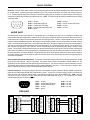
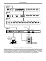
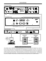
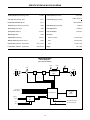
EQ281/8
&
EQ282/8
Digitally Controlled
1/3-Octave Equalizers
operation manual
®
6/12/98
Biamp Systems, 10074 S.W. Arctic Drive, Beaverton, Oregon 97005 U.S.A. (503) 641-7287 http://www.biamp.com
an affiliate of Rauland Borg Corp.
EQ281/8 & EQ282/8
TABLE OF CONTENTS
INTRODUCTION
Front Panel
pg. 2
Rear Panel
pg. 3
Setup
Logic Inputs
RS-232 Control
Applications
pgs. 4~6
pg. 7
®
ADVANTAGE EQ281/8 & EQ282/8 provide one or two channels of digitally
controlled 1/3-octave equalization in a single rack-space unit. Input levels and
28 filter bands, as well as high-pass & low-pass filters, are all adjusted via
computer. Eight presets (per channel) are recalled via contact-closures, thirdparty controllers, or computer. Filter design utilizing Constant-Q technology
guarantees precise system tuning with less filter interaction, better filter
combining, and constant filter bandwidth at any setting. EQ281/8 & EQ282/8
are covered by a five-year warranty.
pgs. 8~9
pgs. 10~11
EQ281/8 & EQ282/8 features include:
♦ single-channel (EQ281/8) & dual-channel (EQ282/8) models
Specifications & Block Diagram
pg. 12
Warranty
pg. 13
♦ 28 digitally controlled filters (per channel) on ISO frequencies
♦ Constant-Q technology provides precision system tuning
♦ filters adjustable ±12dB in 1dB steps or ±6dB in 0.5dB steps
♦ channel input levels adjustable ±12dB in 1dB steps (plus off)
♦ high-pass filters (12dB per octave) adjustable 9.1Hz~171.9Hz
♦ low-pass filters (12dB per octave) adjustable 1.9kHz~34.7kHz
♦ eight non-volatile memory presets available (per channel)
♦ logic inputs allow selection of presets via contact-closures
♦ RS-232 serial port for computer or third-party controllers
®
♦ PC control software for Windows 95 & serial cable included
♦ device number switch & link port for controlling multiple units
♦ baud rate switch provides choice of communications rates
♦ front panel indicators for peak, bypass, & selected presets
♦ balanced inputs and outputs on plug-in barrier strip terminals
♦ optional external pink-noise ‘masking’ generator (PNG200)
♦ modular ±12 Volt DC Out jack for powering external devices
♦ incorporates AES recommended grounding practices
♦
marked and UL / C-UL listed power source
♦ covered by Five-Year "Gold Seal" Warranty
?
After reading this manual, if you have any questions or need technical
assistance, please call Biamp Systems toll-free 1-800-826-1457.
E-mail: [email protected] Web-Site: www.biamp.com
☎
1
FRONT PANEL
ADVANTAGE EQ 281/8
Digitally Controlled EQ
preset
peak
preset
peak
bypass
peak
on
ADVANTAGE EQ 282/8
Digitally Controlled EQ
preset
Channel 1
Preset: This seven segment LED display indicates which
preset is currently selected. There are eight presets available
(per channel), which can be recalled from non-volatile memory
via RS-232 or Logic Input control. Each preset stores settings
for input level, 28 filter bands, a high-pass filter, and a low-pass
filter. These settings are adjusted, and presets are stored, via
RS-232 control, using the PC Control Software and serial cable
provided with the equalizer (see Setup on pg. 4). The equalizer
may also be controlled via RS-232 from third-party controllers.
bypass
bypass
on
Channel 2
Peak: This red LED indicates output level has reached +14dBu
balanced (+8dBu unbalanced). When the Peak indicator lights,
10dB of headroom remains before clipping. If increased signal
levels or equalizer adjustments cause the Peak indicator to light
frequently, reduce the equalizer input level to avoid distortion
caused by overdriving the equalizer output section.
Bypass: This red LED indicates the equalizer has been
bypassed via RS-232 control. When bypassed, all filters are
temporarily set flat, the high-pass & low-pass filters are set to
their extremes (9.1Hz & 34.7kHz respectively), and the equalizer
input levels are set to unity gain (see Setup on pg. 6).
On: This red LED indicates power is applied to the equalizer.
2
REAR PANEL
~
output
32
16
8
4
2
1
15 watts
class 2 wiring
DC out
device #
serial port
link port
~
baud rate
an affiliate of
Rauland-Borg Corp.
logic inputs
MADE IN U.S.A.
device #
input
serial port
link port
baud rate
BIAMP SYSTEMS
output
input
Portland, Oregon
last
2400
9600
19200
32
16
8
4
2
1
DC out
BIAMP SYSTEMS
Portland, Oregon
output
27V
50/60 Hz
15 watts
class 2 wiring
input
last
2400
9600
19200
27V
50/60 Hz
an affiliate of
Rauland-Borg Corp.
channel 2
logic inputs
AC Power Cord: The power transformer provides 27 Volts AC
to the equalizer, and is detachable via a 5-pin DIN connector.
The equalizer has two internal ‘self-resetting’ fuses (there are no
user servicable parts inside the unit). If the internal fuses blow,
they will attempt to re-set after a short period. However, this
may be an indication that the equalizer requires service.
MADE IN U.S.A.
channel 1
Baud Rate: This 6-gang DIP switch allows an equalizer to be
assigned a specific communications baud rate. Baud rates
available are 2400, 9600, & 19200 bps. The factory default is
9600 bps. Only one baud rate should be selected at a time, by
raising the corresponding switch. The two switches on the far
right are not used. The switch on the far left (labelled ‘last’) is
used when connecting multiple devices in a ‘Link Port to Serial
Port’ configuration (see Link Port). From the factory, the ‘last’
switch is up. When connecting multiple devices, the ‘last’ switch
must be switched down on all devices except the final (‘last’)
device in the system (the device with no Link Port connection).
DC Out: This 6-pin Modular jack supplies ±12 Volts DC, for
powering external accessory devices. The EQ281/8 DC Out
provides up to 100mA maximum current. The EQ282/8 DC Out
provides only 10mA maximum current.
Logic Inputs: This 25-pin Sub-D (female) connector provides
16 logic input terminals, plus 9 ground terminals (see Logic
Inputs on pg. 7). Once equalizer settings are adjusted (and
presets are stored) via RS-232 control, the Logic Inputs can be
used to recall presets from non-volatile memory using simple
switches or contact-closures. The EQ281/8 Logic Inputs have
the following pin assignments (right-to-left & top-to-bottom):
Pins 1~8) recall Presets 1~8; Pins 9~16) no operation; Pins
17~25) switch ground points. The EQ282/8 Logic Inputs have
the following pin assignments (right-to-left & top-to-bottom):
Pins 1~8) recall Presets 1~8 (channel 1); Pins 9~16) recall
Presets 1~8 (channel 2); Pins 17~25) switch ground points.
Logic Input functions may be programmed using the PC Control
Software and serial cable provided with the equalizer (see Setup
on pg. 4).
Device #: This 6-gang DIP switch allows an equalizer to be
assigned a specific device number. Up to 64 different device
numbers (0~63) may be assigned to allow RS-232 control of
®
multiple ADVANTAGE products in a common system. From
the factory, an equalizer is assigned Device # 1.
Serial Port: This 9-pin Sub-D (male) connector provides an
RS-232 Serial Port for remote control via computer or third-party
controllers (see RS-232 Control on pg. 8). The Serial Port has
the following pin assignments (left-to-right & top-to-bottom): Pin
1) not used; Pin 2) Receive Data (RxD) input; Pin 3)
Transmit Data (TxD) output; Pin 4) Data Terminal Ready
(DTR) output; Pin 5) Ground; Pin 6) not used; Pin 7)
Request To Send (RTS) output; Pin 8) not used; Pin 9) not
used. PC Control Software and a serial cable are provided for
®
programming via Windows 95 (see Setup on pg. 4). NOTE:
The Serial Port can also transmit commands which are received
via the Logic Inputs (see Setup on pg. 5).
Output: These plug-in barrier strip terminals provide a
balanced line-level output (per channel). For balanced
connections, wire high to (+), low to (-), and ground to ( ). For
unbalanced connections, wire high to (+) and ground to ( ),
leaving (-) unconnected. Signal level will be reduced by 6dB
when outputs are unbalanced.
ý
Link Port: This 9-pin Sub-D (female) connector provides a Link
®
Port for RS-232 control of multiple ADVANTAGE products (see
RS-232 Control on pg. 9). The Link Port of one device simply
connects to the Serial Port of the next device (and so forth).
Link cables are available as an option (Biamp #909-0057-00).
NOTE: All but the final device in a system should have its ‘last’
switch down (see Baud Rate). The Link Port has the following
pin assignments (right-to-left & top-to-bottom): Pin 1) not used;
Pin 2) Transmit Data (TxD) input; Pin 3) Receive Data (RxD)
output; Pin 4) not used; Pin 5) Ground; Pin 6) not used; Pin
7) not used; Pin 8) not used; Pin 9) not used. NOTE: The
Link Port can also transmit commands which are received via
the Logic Inputs (see Setup on pg. 5).
ý
Input: These plug-in barrier strip terminals provide a balanced
line-level input (per channel). For balanced connections, wire
high to (+), low to (-), and ground to ( ). For unbalanced
connections, wire high to (+), and ground to both (-) & ( ). The
Input level is adjustable via RS-232 control, and has a range of
±12dB in 1dB steps, plus off.
ý
ý
3
SETUP
®
All equalizer parameters are adjustable using the Windows 95 'PC Control Software' and serial cable provided with the unit. The PC
®
Control Software provides programs for the EQ281/8 & EQ282/8, as well as other ADVANTAGE products. The equalizer programs
include three different control screens (Main, Button Definition, & Configuration Options), which are described on the following pages.
Once the software is started (and Comm Port Configuration is set), the three control screens are accessable through the drop-down menus
at the top of the opening screen. The Main screen appears whenever an equalizer file is opened. Button Definition & Configuration
Options screens are then available from the Configure EQ282/8 (EQ281/8) menu. The File menu provides functions such as open, close,
save, etc. The Edit menu allows copy/paste & flat-curve functions. The Settings menu recalls the Comm Port Configuration screen. The
Window menu arranges the active product screens. The Help menu explains the available adjustments. To install PC Control Software:
®
®
Select ‘Run’ from Windows 95 ‘Start’ menu, and enter A:\SETUP. System Requirements: Windows 95 with 8M of RAM & 2M of available
hard disk space (serial port required for ‘on-line’ operation).
MAIN SCREEN
The Main Screen is used to adjust the equalizer (channel) input level, 28 filter bands, high-pass filter, and low-pass filter settings, as well as to
store & recall eight memory presets. Adjustments are made with the computer mouse (or keyboard). Settings are adjusted by dragging the
corresponding ‘faders’ (or left-clicking the arrow buttons). Each filter band fader provides 25 gain steps, in 1 dB increments (±12dB). Left-clicking
on +/-12 dB will instead select 0.5 dB increments (±6dB). Left-clicking above or below a fader will adjust the gain three steps at a time. High Pass
& Low Pass filters provide 16 frequency steps. Left-clicking to the left or right of the fader will adjust the frequency 4 steps at a time. The Level
fader provides 26 gain steps (±12dB, plus off). Right-clicking in the filter band area opens a drop-down menu, which allows copy/paste & flat curve
functions. Left-clicking a Preset button will recall the corresponding preset from non-volatile memory (presets are stored automatically). Leftclicking the Bypass button will temporarily bypass filter & level settings (see Configuration Options screen on pg. 6). On the EQ282/8, left-clicking
on Linked Controls allows any equalizer adjustments to affect both channels. This is effective for stereo equalization. After initial adjustments, the
controls may again be un-linked, to allow fine tuning of the individual channels. The title bar across the top of the Main screen will indicate the
Device #, the custom Device Name, and the model of product being controlled. The PC Control Software can operate ‘off-line’ (with no product
connected) by opening a ‘new’ file for the desired product. The Device # for ‘off-line’ files is assigned sequentially as a negative number.
4
SETUP
BUTTON DEFINITION SCREEN
The Button Definition screen is used to assign specific ‘recall preset actions’ to the Logic Inputs (and remote control buttons). Logic Inputs
allow remote control of preset selection via external circuits, such as switches, contact-closures, active driver circuits, and/or ‘opencollector’ logic outputs (see Logic Inputs on pg. 7). From the factory, Logic Inputs 1~8 are programmed to recall presets 1~8 respectively
(Channel 1 on an EQ282/8). On an EQ282/8, Logic Inputs 9~16 are programmed to recall presets 1~8 for Channel 2. On an EQ281/8,
Logic Inputs 9~16 are programmed to do nothing. However, using the Button Definition screen, each Logic Input may be assigned
different ‘recall preset actions’. Left-clicking on a numbered button will select that Logic Input to be defined. Left-clicking on Action
(Channel 1 Action or Channel 2 Action on EQ282/8) will open a drop-down menu of the available recall preset actions (for that channel).
Left-clicking the desired recall preset action will then assign that action to the currently selected Logic Input. An EQ282/8 can have a single
Logic Input defined to recall presets for both Channel 1 & Channel 2. Since Logic Inputs are controlled by switches, contact-closures, etc.,
each Logic Input may be assigned certain recall preset actions to perform when the switch is ‘opened’, and different recall preset actions to
perform when that switch is ‘closed’. The Button Definition screen also includes the ability to assign specific recall preset actions to be
performed each time the equalizer is powered up. Left-clicking Power Up Actions selects this function to be defined. Power Up Actions
are then assigned in exactly the same way as they would be for a Logic Input. From the factory, the equalizers have no Power Up Actions
assigned. When an equalizer is powered up, and no Power Up Actions have been assigned, the equalizer will automatically recall the last
settings which existed before it was powered off. Left-clicking on Echo Character opens a drop-down menu, which allows the ‘echo’
character for the selected Logic Input to be changed. This is the RS-232 equivalent ASCII character which will be transmitted via the Serial
Port, whenever that Logic Input is switched. From the factory, no echo characters are assigned to Logic Inputs 1~16. Changing the echo
character is used primarily for customizing remote control commands amongst various RS-232 controlled products within a system (see
RS-232 Control on pg. 8). NOTE: . Unlike other remote controls, the equalizer Logic Inputs do not include a ‘repeat’ function. Therefore,
a Logic Input in an ‘opened’ or ‘closed’ state will not continuously repeat an echo character via RS-232. Although the equalizers do not
®
accept infrared or wall-mount remote controls themselves, they can still receive echo characters (via RS-232) from other ADVANTAGE
products which are utilizing these types of remote controls. From the factory, Remote Control Buttons have equivalent ASCII characters
permanently assigned to them (see RS-232 Control on pg. 8). Therefore, recall preset actions can be assigned to Remote Control Buttons
in the same way they are assigned to Logic Inputs. Left-clicking on Clear opens a drop-down menu, which allows recall preset actions to
be cleared from the selected Logic Input (or all Logic Inputs). Left-clicking on Default opens a drop-down menu, which allows recall preset
actions to be set back to the factory default for the selected Logic Input (or all Logic Inputs). Left-clicking on Try It causes the recall preset
actions currently assigned to the selected Logic Input to be performed by the equalizer. Left-clicking on Help provides additional
instruction. Left-clicking on Close will close the Button Definition screen.
5
SETUP
CONFIGURATION OPTIONS SCREEN
The Configuration Options screen is used to select options which customize the operation of the equalizer. At the top of the Configuration
Options screen, the Serial Number and Firmware Version of the equalizer will be displayed. The PC Control Software can operate ‘off-line’
(with no product connected) by opening a ‘new’ file for the desired product. The Serial Number and Firmware Version are not displayed for
‘new’ (‘off-line’) files. Left-clicking on Device Name allows a custom name to be given to the particular equalizer, by entering up to 30
characters of text. The Device Name will be stored in the equalizer memory, and will be displayed on the title bar of the Main screen
whenever that equalizer is accessed with the software. Left-clicking on Bypass mode also sets the level control to unity gain will remove
the check-mark, and thereby prevent Bypass from changing any current input level settings. Left-clicking on Bypass mode also sets the
high-pass and low-pass filters to their extremes will remove the check-mark, and thereby prevent Bypass from changing any high-pass
filter or low-pass filter frequency settings. Left-clicking on Restore Defaults will set all Configuration Options back to their factory defaults.
6
LOGIC INPUTS
Sixteen Logic Inputs are available on a rear panel 25-pin Sub-D (female) connector. Logic Inputs allow remote control of preset selection
via external circuits, such as switches, contact-closures, active driver circuits, and/or ‘open-collector’ logic outputs. From the factory, Logic
Inputs 1~8 are programmed to recall presets 1~8 respectively (Channel 1 on an EQ282/8). On an EQ282/8, Logic Inputs 9~16 are
programmed to recall presets 1~8 for Channel 2. On an EQ281/8, Logic Inputs 9~16 are programmed to do nothing. However, Logic
Inputs may be individually programmed to perform other functions, using the PC Control Software and serial cable provided with the
equalizer (see Setup on pg. 4). Since Logic Inputs are controlled by switches, contact-closures, etc., each Logic Input may be assigned
two functions (one for switch ‘closed’ and one for switch ‘open’). Logic Inputs may be programmed to have no effect on the equalizer, but
®
instead trigger ASCII characters which affect other ADVANTAGE products via RS-232 (see RS-232 Control on pg. 8).
Logic Inputs have the following pin assignments (right-to-left & top-to-bottom): Pins 1~16) Logic Inputs 1~16; Pins 17~25) Ground.
13 12 11 10 9
8 7
6
5 4
3
2
25 24 23 22 21 20 19 18 17 16 15 14
logic inputs
1
Pins
Functions
Factory Programming
#1~8
Logic Inputs 1~8
Preset Select 1~8 (channel 1 - EQ282/8)
#9~16
Logic Inputs 9~16
Preset Select 1~8 (channel 2 - EQ282/8)
#17~25
common ground
switch ground points (not programmable)
When nothing is connected to a Logic Input, an internal pull-up resistor keeps it at a ‘high’ idle state (+5.0 VDC). The Logic Input is
activated when its input goes ‘low’ (less than +0.8 VDC), and is de-activated when its input goes ‘high’ (greater than +2.4 VDC). A Logic
Input is controlled in one of three ways: 1) Use an NPN style ‘open-collector’ logic output from an external device (such as an
®
ADVANTAGE PMX84 or DRC4+4) to short the Logic Input to ground. 2) Use a switch, relay, or other contact-closure (such as from a
third-party controller) to short the Logic Input to ground. 3) Use an active TTL output driver circuit (such as from a third-party controller) to
actively drive the Logic Input to a ‘high’ or ‘low’ state.
Multiple contact-closures or ‘open-collector’ logic outputs or may be wired in parallel to a single Logic Input (see diagram below). Likewise,
a single contact-closure or ‘open-collector’ logic output may be wired in parallel to multiple Logic Inputs. However, these circumstances
may be rare, since the Logic Inputs can be individually programmed for specific preset selections. Logic Outputs and contact-closures
should be rated for at least 5 Volts / 1mA operation. Low-current / dry-contact closures are recommended for reliability. Active output
driver circuits should not exceed a signal range of 0~5 Volts DC, and should have a minimum pulse width of 100 milli-seconds. Logic Input
impedances are approximately 10k ohms.
multiple switches to single Logic Input
(momentary switches recommended)
single switch to multiple Logic Inputs
7
RS-232 CONTROL
The EQ281/8 & EQ282/8 have an RS-232 compatible Serial Port, which allows them to be controlled by a computer (see Rear Panel:
Serial Port on pg. 3). In addition to the PC Control Software, the EQ281/8 & EQ282/8 offer two other methods of computer control.
®
Control Button Emulation: This method allows the computer to emulate the operation of an ADVANTAGE infrared or wall-mount pushbutton remote control. Using this method, the computer outputs ASCII characters, which are equivalent to pressing ‘buttons’ on a remote
control. Control Button Emulation allows the computer to utilize up to forty button definitions (see Setup on pg. 5). When using up to four
devices in a system, Control Button Emulation also allows the computer to designate which device or devices should react to each control
button command. NOTE: Although the EQ281/8 & EQ282/8 do not accept infrared or wall-mount remote controls themselves, they can
still receive the corresponding ASCII characters from other ADVANTAGE® products which are utilizing these types of remote controls.
Advanced Computer Control: This method provides advanced commands, which allow the computer to retrieve or edit level & equalizer
settings, presets, control button definitions, and a variety of other functions. The computer may also emulate control buttons. Using this
method, the computer may designate up to sixty-four devices, and may create unlimited presets. The computer may also provide ‘realtime’ display of equalizer settings.
This manual only describes the Control Button Emulation method of computer control. For complete details about using the equalizers with
a computer, including Advanced Computer Control, contact Biamp Systems for the manual "Computer Control of EQ281/8 & EQ282/8".
®
Each push-button on an ADVANTAGE infrared or wall-mount remote control corresponds to one character in the standard ASCII
character set. The character equivalents are summarized in the following table. This table includes all forty of the possible buttons, their
button numbers, their ASCII code equivalents, and their factory default button definitions (see Setup on pg. 5). NOTE: From the factory,
there are no functions assigned to any of the control buttons.
button 01
button 02
button 03
button 04
button 05
button 06
button 07
button 08
button 09
button 10
button 11
button 12
button 13
button 14
B
C
D
E
F
G
H
I
J
K
L
M
N
O
NOP (no operation)
NOP (no operation)
NOP (no operation)
NOP (no operation)
NOP (no operation)
NOP (no operation)
NOP (no operation)
NOP (no operation)
NOP (no operation)
NOP (no operation)
NOP (no operation)
NOP (no operation)
NOP (no operation)
NOP (no operation)
button 15 P NOP (no operation)
button 16 Q NOP (no operation)
button 17 R NOP (no operation)
button 18 S NOP (no operation)
button 19 T NOP (no operation)
button 20 U NOP (no operation)
button 21 V NOP (no operation)
button 22 W NOP (no operation)
button 23 X NOP (no operation)
button 24 Y NOP (no operation)
button 25 Z NOP (no operation)
button 26 [ NOP (no operation)
button 27 \ NOP (no operation)
button 28 ] NOP (no operation)
button 29
button 30
button 31
button 32
button 33
button 34
button 35
button 36
button 37
button 38
button 39
button 40
^
_
'
b
c
d
e
f
g
h
i
j
NOP (no operation)
NOP (no operation)
NOP (no operation)
NOP (no operation)
NOP (no operation)
NOP (no operation)
NOP (no operation)
NOP (no operation)
NOP (no operation)
NOP (no operation)
NOP (no operation)
NOP (no operation)
The computer can initiate any functions that are assigned to a control button or Logic Input, by simply transmitting the equivalent control
button ASCII character. When interfacing the equalizer to a computer, the computer must be aware that the equalizer will ‘echo’ all
characters it receives (both from computer and Logic Inputs) via the Serial Port Transmit Data (TXD) output signal.
®
When using Control Button Emulation, up to four ADVANTAGE products may be connected together, and addressed individually,. When
multiple units are used, each unit is assigned a unique "Device #" (see Rear Panel: Device # on pg. 3). Normally, all units would react to
control button commands. However, a computer can send commands to specific units, by preceding each command with a "device select
prefix" character (see following table). Only those units whose Device #s are specified will respond to the command which follows. If a
command is not immediately preceded by a device select prefix character, then all units in the system will react to that command.
Select Device 1
Select Device 2
Select Devices 1 & 2
Select Device 3
Select Devices 1 & 3
l
m
n
o
p
Select Devices 2 & 3
Select Devices 1 & 2 & 3
Select Device 4
Select Devices 1 & 4
Select Devices 2 & 4
8
q
r
s
t
u
Select Devices 1 & 2 & 4
Select Devices 3 & 4
Select Devices 1 & 3 & 4
Select Devices 2 & 3 & 4
Select Devices 1 & 2 & 3 & 4
v
w
x
y
z
RS-232 CONTROL
Serial Port: The 9-pin Sub-D (male) connector on the equalizer rear panel provides the RS-232 compatible serial interface signals used
for computer control. The Serial Port transmits serial data on pin 3 (TxD), receives serial data on pin 2 (RxD), and provides a ground on
Pin 5. The Data Terminal Ready (DTR) & Request To Send (RTS) output signals are connected to a positive voltage source (through a
resistor) and are always asserted when the equalizer power is on. NOTE: The Serial Port will also transmit commands which are received
via the Logic Inputs
1
2
6
3
7
4
8
pin #1
pin #2
pin #3
pin #4
pin #5
5
9
=
=
=
=
=
not used
Receive Data (RxD) input
Transmit Data (TxD) output
Data Terminal Ready (DTR) output
ground
pin #6
pin #7
pin #8
pin #9
=
=
=
=
not used
Request To Send (RTS) output
not used
not used
serial port
The equalizer only requires receive data (pin 2), transmit data (pin 3), and signal ground (pin 5) to be connected for successful data
communications (see cable diagram below). However, the PC may require that signals be present on the data set ready, clear to send, or
carrier detect inputs, as well as the receive data, transmit data, and signal ground pins. Success or failure depends entirely on the actual
computer hardware and software being used. When trying to solve an interfacing problem, the most important thing to remember is that an
output of one device should connect to one or more inputs of the other device, and that two outputs should never be connected together.
Also, keep in mind that the RS-232 specification calls for the cable length to be no greater than 50 feet (although it is not unusual to be
able to operate over distances of 150 to 250 feet), and the connectors must be of the appropriate gender (male or female) to mate
properly. For best results, a shielded cable should be used, with the shield connected to signal ground. Since the equalizer serial interface
ground is also tied (indirectly) to the analog signal ground, undesirable ground loops may occur when the equalizer is connected to a PC (if
the system grounding is not carefully designed). For best performance, the PC ground and the chassis ground of the equalizer should be
at the same potential, and the PC should get AC power from the same source as the equalizer (and any other audio equipment which is
connected to the equalizer).
Serial Port Data Communications Parameters: The equalizer communicates through the Serial Port at the factory selected rate of 9600
bits per second, with 8 data bits, 1 stop bit, and no parity. The equalizer utilizes a subset of the standard 7-bit ASCII character set. The
eighth data bit of each character (the most significant bit) should always be 0. The computer should not echo the characters it receives.
The computer should not be set for either hardware (DTR) or software (XON/XOFF) flow control. The baud rate may be changed to either
2400 or 19,200 bits per second by means of the rear panel Baud Rate DIP switches.
Link Port Connections: The 9-pin Sub-D (female) connector on the equalizer rear panel provides the RS-232 compatible serial interface
®
signals used for linking multiple ADVANTAGE products within a system. The Link Port of one device simply connectes to the Serial Port
of the next device, and so forth (see diagram below). Link cables are available as an option (Biamp #909-0057-00). NOTE: All but the
final device in a system should have its ‘last’ switch down (see Rear Panel: Baud Rate on pg. 3). The Link Port will also transmit
commands which are received via the Logic Inputs.
5
4
9
3
8
2
7
pin #1
pin #2
pin #3
pin #4
pin #5
1
6
=
=
=
=
=
not used
Transmit Data (TxD) output
Receive Data (RxD) input
not used
ground
pin #6
pin #7
pin #8
pin #9
=
=
=
=
not used
not used
not used
not used
link port
PC
CD
RxD
TxD
DTR
gnd
DSR
RTS
CTS
RI
serial port
1
2
3
4
5
6
7
8
9
male
1
2
3
4
5
6
7
8
9
female
Serial Cable
(shield)
serial port
1
2
3
4
5
6
7
8
9
female
1
2
3
4
5
6
7
8
9
male
EQ
EQ
n/a
TxD
RxD
n/a
gnd
n/a
n/a
n/a
n/a
n/a
RxD
TxD
DTR
gnd
n/a
RTS
n/a
n/a
9
link port
1
2
3
4
5
6
7
8
9
female
1
2
3
4
5
6
7
8
9
male
Link Cable
(shield)
serial port
1
2
3
4
5
6
7
8
9
female
1
2
3
4
5
6
7
8
9
male
unit 2
n/a
RxD
TxD
DTR
gnd
n/a
RTS
n/a
n/a
APPLICATIONS
ADVANTAGE
DRC 4+4
®
ADVANTAGE DRC 4+4
remote 2
Digital Remote Control
remote 3
remote 4
VCA control
voltage outputs
MADE IN U.S.A.
DC out
ADVANTAGE
RCII
patch
serial port &
logic outputs
gnd IR2 IR3 gnd IR2 IR3 gnd IR2 IR3 gnd 8
7
6
in/out
4
5
patch
in/out
3
patch
2
in/out
patch
1
in/out
®
VCA control voltage inputs
ADVANTAGE RCII
Remote Control
MADE IN U.S.A.
patch
DC out
DC in
+10V gnd RC4 RC3 RC2 RC1
4
in/out
patch
in/out
3
patch
2
in/out
patch
1
in/out
ADVANTAGE®
ONE
+48VDC 4W
Class 2
E17934
DC out main out main stack main
patch
±12VDC 15W
Class 2
pad
pad
in
patch
8
ADVANTAGE
EQ281/8
7
pad
in
patch
6
pad
in
patch
pad
in
patch
5
®
~
4
output
pad
in
patch
3
in
patch
2
1
device #
BIAMP SYSTEMS
input
Portland, Oregon
last
2400
9600
19200
32
16
8
4
2
1
DC out
pad
in
patch
to amplifier
27V
50/60 Hz
15 watts
class 2 wiring
pad
in
patch
link port
serial port
baud rate
an affiliate of
Rauland-Borg Corp.
logic inputs
MADE IN U.S.A.
ADVANTAGE®
RP-S4
Computer,
AMX®, or
CRESTRON®
controller
1
2
3
4
Presets 1~4
RP-S4
* jumpers removed for
momentary operation
Equalization and Remote Control of a Mono Sound System
®
®
®
This application shows an ADVANTAGE ONE, an ADVANTAGE DRC 4+4, and an ADVANTAGE RCII connected together to provide an
eight input mic/line mixer with remote control of channel levels. This could be any mono sound system. The EQ281/8 provides up to eight
®
selectable preset equalization curves, to accommodate changes in acoustics or program material. An ADVANTAGE RP-S4 is connected
to the EQ281/8 Logic Inputs for selecting Presets 1~4. A custom switch panel can be used to access all eight presets. The EQ281/8 Link
Port is connected to the DRC 4+4 Serial Port. This allows remote control and preset selection, not only of equalization, but of channel
levels as well. Equalization and channel levels are controlled via RS-232, while only preset selection is controlled via switches.
10
APPLICATIONS
®
ADVANTAGE SPM 522D
BIAMP SYSTEMS
Portland, Oregon
outputs
L
R
R
an affiliate of
Rauland-Borg Corp.
L
zone
limit
main
limit
zone
main
3
2
1
level
level
level
mic 1
pad
limit
main out
sig pres
high
override
gnd
low
gnd
IR3
gnd
IR3
IR2
gnd
remote display
signal present
on
R
-20dB 0dB
3
override
sensitivity
0
DC
out
-20dB 0dB
limit
2
1
chassis gnd
phtm mute
power
2
+10
1
inputs
IR2
zone out
trim
0dB
30dB
-20dB 0dB
serial port
mic 1
patch
stereo
mono
27V ~
15 Watts MADE IN U.S.A.
50/60 Hz
class 2 wiring
L
10
5
4
level
level
-20dB 0dB
L R
L
mic 2
pad
trim
phtm mute
power
0dB
30dB
signal present
on
-20dB 0dB
translator override
remote
4
5
R
mic 2
patch
+10
override
®
ADVANTAGE CPA 130
level 2
115V:
3A SB Fuse
+
input 2
--- gnd
+
input 1
--- gnd
level 1
ADVANTAGE
CPA 130
115V
230V:
1.5A SB Fuse
output 2
AC Fuse
E
---
output 1
+
+
---
MADE IN U.S.A.
stereo
mono bridge
F
US
FU
S
115/230 VAC
E
F US E
50/60 Hz
300 Watts max
to Room B speakers
to Room A speakers
ADVANTAGE® EQ282/8
~
output
32
16
8
4
2
1
15 watts
class 2 wiring
DC out
device #
BIAMP SYSTEMS
input
serial port
link port
baud rate
output
input
Portland, Oregon
last
2400
9600
19200
27V
50/60 Hz
an affiliate of
Rauland-Borg Corp.
channel 2
logic inputs
MADE IN U.S.A.
channel 1
ADVANTAGE®
RP-S4
Computer,
AMX®, or
CRESTRON®
controller
®
ADVANTAGE
RP-S4
Room A
1
2
3
4
Room B
1
2
3
4
Presets 1~4
RP-S4
RP-S4
* jumpers removed for
momentary operation
Equalization of a Mono Sound System with Two Zones
®
This application shows an ADVANTAGE SPM522D providing program source & mic/line mixing to two independent mono outputs for
Room A & Room B sound systems, with an ADVANTAGE CPA130 providing power for the speakers in each room. This could be any
mono sound system with two zones. The EQ282/8 provides up to eight selectable preset equalization curves per room, to accommodate
®
changes in acoustics or program material (including room combining). Two ADVANTAGE RP-S4s are connected to the EQ282/8 Logic
Inputs for selecting Presets 1~4 in each room. Custom switch panels can be used to access all eight presets per room. The EQ282/8 Link
Port is connected to the SPM522D Serial Port. This allows remote control and preset selection, not only of equalization, but of sources and
levels as well. Equalization, sources and levels are controlled via RS-232, while only preset selection is controlled via switches.
11
SPECIFICATIONS & BLOCK DIAGRAM
31.5Hz~16kHz
Filter Frequencies (ISO centers):
+0/-0.5dB
Frequency Response (20Hz~20kHz @ +4dBu):
±12dB in 1dB steps or
THD + Noise (20Hz~20kHz @ +4dBu):
<0.01%
Intermodulation Distortion (SMPTE):
<0.01%
Hum & Noise (20Hz~20kHz @ unity, filters flat):
-88dBu
Input Gain Range (programmable):
Dynamic Range (20Hz~20kHz):
109dB
Power Requirements:
120/240VAC
>10k ohms
Power Consumption:
15 watts max.
Input Impedance (balanced):
Filter Gain Range (programmable):
±6dB in 0.5dB steps
+19dBu
Maximum Input Level:
±12dB & off
Dimensions:
200 ohms
Height (1 rack space)
1.75 inches (44mm)
+24dBu
Width
19 inches (483mm)
High-Pass Filter (12dB/octave - programmable):
9.1Hz~171.9Hz
Depth
7 inches (178mm)
Low-Pass Filter (12dB/octave - programmable):
1.9kHz~34.7kHz
Output Impedance (balanced):
Maximum Output Level (balanced into 600Ω):
7 lbs. (3.18kg)
Weight:
EQ281/8 & EQ282/8
Block Diagram
(one channel shown)
31.5Hz
16kHz
level
peak
detect
input
+
−
gnd
LPF
HPF
logic inputs
(preset select)
microprocessor
receive
send
output
1/3 octave
Constant-Q
filters
RS-232
serial
port
+
−
gnd
non-volatile
RAM
memory
baud rate DIP switch
link
port
device # DIP switch
12
WARRANTY
BIAMP SYSTEMS IS PLEASED TO EXTEND THE FOLLOWING 5-YEAR
LIMITED WARRANTY TO THE ORIGINAL PURCHASER OF THE
PROFESSIONAL SOUND EQUIPMENT DESCRIBED IN THIS MANUAL.
BIAMP Systems expressly warrants this product to be
free from defects in material and workmanship for a
period of 5 YEARS from the date of purchase as a
new product from an authorized BIAMP Systems
dealer under the following conditions.
5. BIAMP SYSTEMS SHALL NOT IN ANY EVENT BE
LIABLE
FOR
SPECIAL,
INCIDENTAL,
OR
CONSEQUENTIAL DAMAGES, INCLUDING LOST
PROFITS, LOSS OF USE, PROPERTY DAMAGE, INJURY
TO GOODWILL, OR OTHER ECONOMIC LOSS OF ANY
SORT. EXCEPT AS EXPRESSLY PROVIDED HEREIN,
BIAMP SYSTEMS DISCLAIMS ALL OTHER LIABILITY TO
PURCHASER OR ANY OTHER PERSONS ARISING OUT
OF USE OR PERFORMANCE OF THE PRODUCT,
INCLUDING LIABILITY FOR NEGLIGENCE OR STRICT
LIABILITY IN TORT.
1. The Purchaser is responsible for completing and
mailing to BIAMP Systems, within 10 days of
purchase, the attached warranty application.
2. In the event the warranted BIAMP Systems product
requires service during the warranty period, BIAMP
Systems will repair or replace, at its option, defective
materials, provided you have identified yourself as the
original purchaser of the product to any authorized
BIAMP Systems Service Center. Transportation and
insurance charges to and from an authorized Service
Center or the BIAMP Systems factory for warranted
products or components thereof to obtain repairs shall
be the responsibility of the purchaser.
6. THIS WARRANTY IS IN LIEU OF ALL OTHER
WARRANTIES EXPRESSED OR IMPLIED.
BIAMP
SYSTEMS EXPRESSLY DISCLAIMS ALL IMPLIED
WARRANTIES OF MERCHANTABILITY AND FITNESS
FOR A PARTICULAR PURPOSE. THE REMEDIES SET
FORTH HEREIN SHALL BE THE PURCHASER'S SOLE
AND EXCLUSIVE REMEDIES WITH RESPECT TO ANY
DEFECTIVE PRODUCT. THE AGENTS, EMPLOYEES,
DISTRIBUTORS, AND DEALERS OF BIAMP SYSTEMS
ARE NOT AUTHORIZED TO MODIFY THIS WARRANTY
OR TO MAKE ADDITIONAL WARRANTIES BINDING ON
BIAMP SYSTEMS.
ACCORDINGLY, ADDITIONAL
STATEMENTS SUCH AS DEALER ADVERTISEMENTS
OR REPRESENTATIONS DO NOT CONSTITUTE
WARRANTIES BY BIAMP SYSTEMS.
3. This warranty will be VOIDED if the serial number
has been removed or defaced; or if the product has
been subjected to accidental damage, abuse, rental
usage, alterations, or attempted repair by any person
not authorized by BIAMP Systems to make repairs; or
if the product has been installed contrary to BIAMP
Systems's recommendations.
7. No action for breach of this warranty may be
commenced more than one year after the expiration of this
warranty.
4. Electro-mechanical fans, electrolytic capacitors,
and the normal wear and tear of appearance items
such as paint, knobs, handles, and covers are not
covered under this warranty.
Thank you for purchasing BIAMP SYSTEMS...
AMERICAN SOUND CRAFTSMANSHIP
Biamp Systems
10074 S.W. Arctic Drive
Beaverton, Oregon 97005
(503) 641-7287
http://www.biamp.com
585.0131.00
13