1
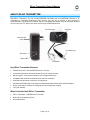
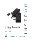
IRLinc Transmitter INSTEON® to IR Converter Model : 2411T IRLinc Transmitter Owner’s Manual TABLE OF CONTENTS ABOUT IRLINC TRANSMITTER ................................................................................................................. 3 Key IRLinc Transmitter Features ............................................................................................................... 3 What is Included with IRLinc Transmitter .................................................................................................. 3 WHAT IS INSTEON? .................................................................................................................................... 4 INSTALLATION ............................................................................................................................................ 5 Preparing to Install IRLinc Transmitter ...................................................................................................... 5 Installing IRLinc Transmitter ...................................................................................................................... 6 USING IRLINC TRANSMITTER ................................................................................................................... 6 CONTROLLING IRLINC TRANSMITTER FROM AN INSTEON CONTROLLER....................................... 7 Linking an INSTEON Controller to IRLinc Transmitter .............................................................................. 7 Unlinking IRLinc from an INSTEON Controller.......................................................................................... 7 CREATING AN INSTEON SCENE ............................................................................................................... 7 ADVANCED FEATURES ............................................................................................................................. 8 Restoring Power to IRLinc Transmitter ..................................................................................................... 8 Resetting IRLinc Transmitter to its Factory Default Settings ..................................................................... 8 X10 PROGRAMMING OPTIONS ................................................................................................................. 8 Setting the X10 Address ............................................................................................................................ 8 Removing the X10 Address ....................................................................................................................... 8 ABOUT INSTEON ........................................................................................................................................ 9 Using Dual-Band INSTEON Devices to Upgrade Your Network ............................................................... 9 Important Note about INSTEON Networks; Split Single-Phase vs. 3-Phase Installation.......................... 9 Further Enhancing Reliability .................................................................................................................... 9 ADDITIONAL RESOURCES ........................................................................................................................ 9 Tutorial Videos ........................................................................................................................................... 9 TROUBLESHOOTING................................................................................................................................ 10 Troubleshooting During Setup ................................................................................................................. 10 Troubleshooting After Setup .................................................................................................................... 11 IRLINC TRANSMITTER IR COMPATIBILITY............................................................................................ 12 Compatible Devices ................................................................................................................................. 12 Incompatible Devices .............................................................................................................................. 13 SPECIFICATIONS, CERTIFICATION, AND WARRANTY ........................................................................ 14 Specifications .......................................................................................................................................... 14 Certification .............................................................................................................................................. 14 Limited Warranty ..................................................................................................................................... 15 IRLinc Transmitter Owner’s Manual ABOUT IRLINC TRANSMITTER With IRLinc Transmitter, you can convert INSTEON commands from any INSTEON Controller to IR commands for controlling audio/visual (A/V) devices. You can set up macros to send several IR commands from a single press of a button. IRLinc is compatible with almost every IR command, allowing you to control your TV, stereo, and much more from your INSTEON devices. IR emitter jack IR sensor Pass-through outlet IR emitter plug Set button Status LED IR emitters Key IRLinc Transmitter Features • Installs and Links to other INSTEON devices in minutes • Conveniently learns IR commands directly from your existing remotes • Macro support – control several devices from a single button press • Compatible with most IR-controlled devices and X10 controllers • Sleek black finish blends in with your A/V equipment • Indicates INSTEON setup mode activity and operational states with a Status LED and beeper • Stores setup state in memory so settings aren’t lost during power outages • Two-year warranty What is Included with IRLinc Transmitter • IRLinc Transmitter – INSTEON to IR Converter • Dual stick-on IR emitters (9 feet) • Quick-Start Guide Page 3 of 15 IRLinc Transmitter Owner’s Manual WHAT IS INSTEON? Since its inception in 2005, INSTEON has become a best-selling home-control networking technology, offering more reliability and flexibility than any other home management system on the market. INSTEON systems are simple, reliable, and affordable. Simple, because each device takes mere minutes to install. Reliable, because every INSTEON device works as a network repeater, ensuring your commands will not be lost. Affordable, because INSTEON can be integrated into any number of devices easily and at a very low cost. An INSTEON home grows in value with each added INSTEON device, making life more convenient, safe, and fun. How Does INSTEON Work? What makes INSTEON the most reliable home automation network is its dual-mesh network. INSTEON devices use both radio frequency (RF) signals and the home’s existing wiring to talk to each other. In an INSTEON network, every INSTEON device also acts as a repeater, receiving and sending every message to all other devices in the network. So by integrating more INSTEON devices you will strengthen the network and ensure no commands will be lost. No central controller or networking setup is required with an INSTEON network. Simply install your devices and then use a series of button presses or taps to Link your devices together. Throughout this Owner’s Manual, you may see the terms “Controller” or “Responder”. These generic INSTEON terms refer to the components of an INSTEON scene, and are used on a scene-by-scene basis. • Controller – sends INSTEON commands to other devices • Responder – reacts to commands sent out by another INSTEON device An INSTEON device may act as a Controller, Responder, or sometimes both. INSTEON networks are also extremely secure. Each INSTEON device is assigned a unique INSTEON ID, so unless neighbors or would-be hackers have access to your particular device’s INSTEON ID, they won’t be able to control your home, even if they are using similar products. Page 4 of 15 IRLinc Transmitter Owner’s Manual INSTALLATION Preparing to Install IRLinc Transmitter CAUTION Read and understand these instructions before installing and retain them for future reference. IRLinc is intended for installation in accordance with the National Electric Code and local regulations in the United States or the Canadian Electrical Code and local regulations in Canada. Use indoors only. IRLinc is not designed nor approved for use on power lines other than 120V 60Hz, single phase. Attempting to use IRLinc on non-approved power lines may have hazardous consequences. Prior to installing IRLinc, please review the entire installation procedure and take the following precautions: • Use indoors or in a properly insulated and weatherproof electrical box only • Don’t plug IRLinc into an outlet controlled by a switch because if the switch is inadvertently turned off, IRLinc won’t have power • Don’t plug IRLinc into a filtered power strip or AC filter • Be sure that the device you want to control is working and that the device’s built-in switch is in the on position • Don’t stack INSTEON home automation devices together by plugging them into each other. Stacked devices may overheat and stop functioning. Also avoid using the pass-through outlets on INSTEON devices for other heat-generating power supplies. • Don’t use IRLinc to control devices that preserve, maintain, or contribute to human or animal safety or life support • Be careful where emitters are plugged in if you plan on using the included IR emitters on a device other than IRLinc. Some similar jacks may have higher voltages than the emitter can handle. If an emitter is plugged into the probe jack, it will be destroyed instantly. • The IRLinc IR emitter jack is designed for use with single/dual IR emitters or blasters and is not compatible with IR repeating systems through a direct connection. For use with these systems, it is recommended to install a sensor compatible with the desired IR repeating system in range/sight of an emitter or blaster connected to the IRLinc IR emitter jack. • For control of more than two IR devices, it is recommended to use an IR blaster located in sight of all your equipment Tips for using the included IR emitters: • Some plasma TVs and compact fluorescent lights may produce IR noise that could interfere with the equipment’s IR sensor. Covering the outside of the emitter with black electrical tape may help. • If the emitter falls off the equipment, clean the sensor area with an alcohol-based cleaner and reapply the sensor • If the foam adhesive doesn’t stick well, apply a very small drop of glue and reapply • IR emitters need to be in direct contact with the equipment’s IR sensor window for best results. Operation may be intermittent if the emitter is just a few inches away from the window. • An extension cable (up to 300 feet) may be used between the emitter and the equipment. A two or three conductor cable with male and female 1/8 inch (3.5 mm) plugs is ideal. If you have any questions, please call: INSTEON Gold Support Line 800-762-7845 Page 5 of 15 IRLinc Transmitter Owner’s Manual Installing IRLinc Transmitter 1) Plug the IR emitter plug into the IRLinc emitter jack 2) Plug IRLinc into a convenient, unswitched wall outlet near your IR equipment HINT: You will need access to the bottom of IRLinc during Linking so you may want to temporarily use an extension cord until setup is complete. The IRLinc Status LED will turn on solid blue 3) Locate the IR sensor for the IR-controlled device you would like to control NOTE: When using the stick-on emitters, it is important to find the IR sensor on the equipment and place the emitter directly over the sensor. Use a flashlight to look into the display or bezel of the equipment to find the sensor. If the sensor is too difficult to find, you can partially cover the front of the equipment with an object or thick cloth. If the remote works, then continue to isolate areas of the uncovered section to narrow down the location of the sensor. 4) Once you have located the device’s IR sensor, hold the emitter where you intend to mount it and then learn and test the IR code a) Double-tap the Set button on IRLinc IRLinc will double-beep and its Status LED will begin blinking b) Point your IR remote control at the bottom of IRLinc, holding it within a couple inches of the IR sensor. Then, tap the IR button to be learned. IRLinc will double-beep and its Status LED will turn on solid If IRLinc beeps eight times, remount the IR emitter and start over from step a c) Test that the IR code has been learned by tapping the Set button on IRLinc IRLinc will beep 5) Remove the peel-off backing from the first IR emitter and mount it over the IR sensor 6) Repeat steps 4 and 5 for the second IR emitter NOTE: Due to heat build-up and the potential for causing damage to this device, it is strongly recommended that you avoid using the front pass-through outlet for stacking INSTEON devices. Also avoid using this pass-through for other heat-generating power supplies. See a tutorial video at: www.smarthome.com/videos/2411T.wmv USING IRLINC TRANSMITTER INSTEON IRLinc responds only to INSTEON ON or OFF commands. ALL ON/OFF or BRIGHT/DIM commands are ignored. NOTE: For any given INSTEON Controller button, the IR commands associated with the ON command are independent of the IR commands associated with the OFF command, for added flexibility. X10 IRLinc responds to the X10 addresses which are programmed and not the commands. For example, if you program A1, IRLinc will respond to any command which starts with A1, such as A1 ON, A1 OFF, etc. Page 6 of 15 IRLinc Transmitter Owner’s Manual CONTROLLING IRLINC TRANSMITTER FROM AN INSTEON CONTROLLER Linking an INSTEON Controller to IRLinc Transmitter To control your IR devices from an INSTEON Controller, follow these steps to Link IRLinc and the Controller together. Refer to your Controller’s Owner’s Manual for detailed instructions on how to properly install and Link it to IRLinc Transmitter. The following will work for the most common INSTEON devices: 1) Set the Controller to Linking Mode. (For most Controllers, press & hold an On or Scene button for 10 seconds or the Set button for 3 seconds.) You will have 4 minutes to complete the next step before Linking Mode automatically times out. 2) Press & hold the Set button on IRLinc until it double-beeps (3 seconds) After a few seconds, IRLinc will double-beep again. DO NOT PROCEED UNTIL YOU HEAR TWO SETS OF DOUBLE-BEEPS. 3) OPTIONAL: If you want to send the IR code to respond to an OFF command instead of an ON command, send an OFF command from the Controller within 30 seconds of performing step 2 NOTE: Sending an OFF command in this step will not affect any other Link. If an OFF command is sent, IRLinc will double-beep 4) Confirm that Linking was successful by tapping the button you just Linked to on the Controller IRLinc will respond appropriately Unlinking IRLinc from an INSTEON Controller If you are going to discontinue using IRLinc, it is very important that you Unlink it from any Linked Controllers. Otherwise, the Controller will retry any commands repetitively, thus slowing down the system. The following will work for the most common INSTEON devices: 1) Set the Controller to Unlinking Mode. (For most Controllers, press & hold an On or Scene button for 10 seconds twice or the Set button for 3 seconds twice.) You will have 4 minutes to complete the next step before Unlinking Mode automatically times out. 2) Press & hold the Set button on IRLinc until it double-beeps (3 seconds) After a few seconds, IRLinc will double-beep again 3) Confirm that Unlinking was successful by tapping the buttons you just Linked from on the Controller IRLinc will no longer respond CREATING AN INSTEON SCENE INSTEON scenes let you activate dramatic lighting moods with the press of just one button. For example, you can set all the lights in a scene to dim to 50% or turn certain lights on while turning others off, all with the tap of a button on a Controller. INSTEON scenes are very easy to set up – just Link more than one Responder to the same On/Off or Scene button on a Controller. Then, when you press any of the Linked buttons on the Controller, all of the INSTEON devices Linked in the scene will respond as a group. Page 7 of 15 IRLinc Transmitter Owner’s Manual ADVANCED FEATURES Restoring Power to IRLinc Transmitter IRLinc stores all of its settings, such as Links to other INSTEON devices, with non-volatile memory. Because settings are saved in this non-volatile memory, they will not be lost in the event of a power failure. Resetting IRLinc Transmitter to its Factory Default Settings The factory reset procedure will clear IRLinc of all INSTEON Links and any programmed X10 addresses. 1) If you are using a Controller to control IRLinc, be sure to Unlink it from the Controller. See Unlinking IRLinc from an INSTEON Controller. 2) Unplug IRLinc from the outlet for 10 seconds 3) While holding down the Set button on IRLinc, plug it back in, making sure not to let go of the Set button 4) Continue to hold down the Set button for 3 seconds and then release A few seconds after you release the Set button, IRLinc will beep and the Status LED will turn on solid X10 PROGRAMMING OPTIONS IRLinc is X10 ready, meaning that it can respond to X10 commands from X10 controllers. However, to operate IRLinc in X10 mode, you must first set up an X10 address. As it ships from the factory or after a factory reset procedure, IRLinc will not have an X10 address set up. Setting the X10 Address You must complete the following before IRLinc will send out X10 commands. You can use any of the 256 possible X10 addresses for the X10 address. 1) Press & hold the Set button on IRLinc until it beeps (3 seconds) The IRLinc Status LED will begin blinking 2) Using an X10 controller, send the desired X10 address, followed by the ON command three times For example, to assign the address A1, you would send “A1 ON A1 ON A1 ON”. IRLinc will double-beep and its Status LED will stop blinking Removing the X10 Address If you are no longer going to control IRLinc with an X10 address, it is very important that you Unlink it, because otherwise IRLinc will respond to the X10 command and may cause IR devices to turn on by themselves. 1) Press & hold the Set button on IRLinc until it beeps (3 seconds) The IRLinc Status LED will begin blinking 2) Using an X10 controller, send the X10 address you would like to remove followed by the OFF command three times For example, to remove X10 address A1, send “A1 OFF A1 OFF A1 OFF”. IRLinc will double-beep and its Status LED will stop blinking and turn on solid Page 8 of 15 IRLinc Transmitter Owner’s Manual ABOUT INSTEON Using Dual-Band INSTEON Devices to Upgrade Your Network What are phases? The majority of single-family homes in North America have two phases (or “legs”) of 110 Volts coming into their electricity panels. From the panel, they are distributed throughout the home, providing power to outlets and wall switches. These phases come together in some parts of the home to provide 220 Volts of power to large appliances, such as an electric oven or pool pump. Why do I need to bridge these phases? Single-band power line devices send commands via the home’s electricity, but only on a single phase. If the command is intended for a device on the opposite phase, there is a good chance the command will go unnoticed. Installing dual-band INSTEON devices, such as Access Points (#2443), on each phase will allow for devices to communicate between the two phases via RF. Dual-band INSTEON devices embody the full potential of a true INSTEON mesh network. Taking the power line band signal and working in conjunction with the RF band signal, its dual-band function plays out in two ways: • Phase bridger – a receiver of commands, reacting to and translating signals sent from one power phase to the opposite via RF • Signal repeater – a participant in an INSTEON network, repeating commands intended for other devices whether those commands are generated from RF or power line-only devices. To ensure reliability, every INSTEON device confirms that it has received a command. If a Controller does not receive this confirmation, it will automatically retransmit the command up to five times. While using at least one dual-band device is required when using an RF-only device, at least two dual-band devices are recommended to ensure reliable communication across two-phase home wiring systems. For larger applications, it is recommended to install at least one dual-band device for every 750 – 1,000 square feet. Search for dual-band INSTEON devices at: www.smarthome.com/dualband Important Note about INSTEON Networks; Split Single-Phase vs. 3-Phase Installation For the best INSTEON network performance, be sure you have properly installed at least two dual-band INSTEON devices. INSTEON has only been officially tested in a split single-phase residential environment but has been known to work in many 3-phase systems, where three dual-band devices are used (one on each phase). However, due to the potential complexity of its troubleshooting, the INSTEON Gold Support Line is unable to support INSTEON in 3phase environments. Further Enhancing Reliability As signals travel via the power line or RF throughout the home, they naturally become weaker the farther they travel. The best way to overcome weakened signals is to increase the coverage of the mesh network by introducing more INSTEON devices. It is possible that some audio-video devices, computers, power strips, or other electrical equipment may attenuate INSTEON signals on the power line. You can temporarily unplug suspected devices to test whether the INSTEON signal improves. If it does, then you can plug in filters that will permanently fix the problem. ADDITIONAL RESOURCES Find home automation solutions, helpful hints, interactive demos, user forums, and more at the Smarthome Learning Center: www.smarthome.com/learningcenter.html Tutorial Videos IRLinc Transmitter Basics www.smarthome.com/videos/2411T.wmv Page 9 of 15 IRLinc Transmitter Owner’s Manual TROUBLESHOOTING Troubleshooting During Setup Figure 1 Page 10 of 15 IRLinc Transmitter Owner’s Manual Troubleshooting After Setup If you have tried these solutions, reviewed this Owner’s Manual, and still cannot resolve an issue you are having with IRLinc, please call: INSTEON Gold Support Line 800-762-7845 Page 11 of 15 IRLinc Transmitter Owner’s Manual IRLINC TRANSMITTER IR COMPATIBILITY Compatible Devices The following devices have been reported to contain at least one IR code compatible with IRLinc: Device Type Brand Model # Air Filter IQ Air Health Pro Apple TV Apple TV N/A Candles FlameFree F327ML5003 CD Pioneer SA-PM17 Digital TV Converter Insignia NS-DXA1-APT DVR TiVo N/A Gaming Xbox V1 w/ IR HDTV Card Hauppague 1600 Juke Box Sony DVP-CX995V Matrix Switcher Channel Vision Pro P1420 PVR Dish Network 622 Harmon / Kardon AVR-254 Onkyo TX-SR302 Pioneer VSX-59TXi RCA RT2360 Sony STRDA-555ES Receiver STR-DGDG920 Set Top Box AT&T / Motorola VIP 1200 Speaker Switch HACS AB8SS iLo 26” Maxent TV Samsung MX50-X3 MX-5020HPM N5065W KP-61HS10 Sony 40” LCD Bravia XBR Toshiba 43A10 Whole House Amp NUVO Concerto XM Receiver AudioVox XR9 Page 12 of 15 IRLinc Transmitter Owner’s Manual Incompatible Devices Delphi XM Radios Parity bits have been found to cause commands after the first to not work. Sony VisionTouch Check for either: • “VisionTouch” printed on the faceplate • Model number ending with “G” • Came with “Air-Egg” remote Almost no learning remote can work with a VisionTouch receiver. The VisionTouch system uses a 45 KHz carrier frequency which uses a unique (non-standard) protocol that is unlearnable by almost every universal remote to date, including the Philips Pronto and Sony’s own models. The problem extends in that you can’t use “normal” Sony remotes or IR codes to control the receiver – even the Sony RM-AV3000 will not work. Affected models include: STR-DA90ESG STR-DE805G STR-DE815G STR-DE905G STR-DE1015G STR-D760Z STR-G1ES STR-G3 STR-GA9ESG TA-VE800G TA-VE810G Sony’s newer receivers advertised with “2-way communications” are fully compatible with regular learning remotes. Sony has since dropped the entire VisionTouch system from their lineup. High Frequency IR Systems Several brands of equipment feature IR systems that operate at frequencies much higher than normal. Though the majority of IR remotes operate in the 30-40 KHz range, several brands such as a Bang & Olufsen, particular Kenwood equipment, and some lighting control systems use a 455 KHz frequency. More unusual and difficult to work are Pioneer and Pioneer Elite components built around 1997 that use a 1.125MHz carrier frequency. Pace Cable Boxes Pace designed a remote for their 1000 and 2000 series digital cable boxes using a protocol not actually intended for remote control use. The IRDA variant was intended for high-speed data transfer over short distances (i.e., from laptop to printer), rather than the slow-speed/long distance requirement of remote controls. The IRDA standard specifically includes a format for remote controls. However, the Pace remotes do not use it. The issue is that trying to learn such codes is much like asking an AM radio to receive FM signals – it simply isn’t possible. At this time, the only remote controls that can offer even partial functionality are certain models from One For All. Even then you’ll most likely have to send the remote to the factory in order for these codes to be added. More recent – and older – Pace models are not affected by this problematic protocol. Parity Bits A somewhat common problem is when a device (such as a cable box) will accept a learned code once but not twice in a row. For instance, you can enter the channel “1 – 2”, but not “3 – 3”. This is not a fault with your new remote, but rather a very hard-to-work-with design employed by your equipment. What happens is your original remote tacks on a “party bit” (sometimes called a “toggle bit”) to the end of each code. So, the first time it sends the code it follows up with a “0”. The next time it ends with “1”. The problem is that a learning remote can only learn or send the signal one way – the way you learned it. Your equipment, unfortunately, will not accept the code again unless it ends with a new parity bit or you send a different code to clear the memory buffer. The most common example of equipment that uses this system is anything that employs the Philips RC5 or RC6 code format - such as Philips or Marantz products, or even Microsoft Media Center Edition remote controls. As the RC5 and RC6 implementation guidelines make parity bit checking optional, not all RC5/RC6 devices will respond the same way to non-alternating learned codes. Some may require parity bits at all times, some may only require it for certain commands (such as “power”), some may use the parity bit only for closely repeated commands (meaning you could send “3-3-3” quickly with the original remote but only slower using a learned code), while some ignore parity bits completely and show no noticeable operational difference with or without. Page 13 of 15 IRLinc Transmitter Owner’s Manual RF Satellites For anyone attempting to consolidate all of their remotes into a single unit, satellite systems can pose a potentially major problem: RF through-the-wall controls. As satellite receivers are the only mainstream A/V devices manufactured today using this technology, IR universal remotes do not include RF support. Satellite receivers come with either an RF-only remote or an RF and IR remote. In the former case, you should contact your manufacturer to determine if your model still has IR compatibility (most today do), in which case you can purchase a new remote or capture the codes from another pre-programmed model. For the latter, you may have to make a choice between RF or IR – most receivers cannot operate with both activated at the same time. This adjustment will be found in the receiver’s setup screens and will probably have to be toggled before the remote will transmit IR signals. Here is a trick for the Sony SAT-A2, A3, and A4 receivers that will allow use of both RF and IR at the same time: • Ensure you are already in RF mode • Press MENU, 9 (SETUP), 1 (REMOTE) • Select “REMOTE CODES” which will bring up a list of various devices • Now select “TV CODES” to bring up the list of TV codes • Press EXIT Your DSS receiver should now be in a mode where it will respond to both IR and RF codes at the same time. However, there are two problems which you may encounter. First, if you use the RF remote in the same room as the receiver it may respond to both RF and IR signals at the same time, as if you pressed the button twice. This does not appear to occur very often. Secondly, if you have another similar DSS receiver you can’t use this trick on it as it always appears to default to the same RF security code (001), meaning that both RF remotes end up controlling both receivers. If your receiver does not include infrared support you will need to continue controlling it via the original remote. Other RF Equipment All other RF equipment, such as most older Bose systems, cannot be controlled by any universal remote currently available. Don’t be confused by remotes advertising RF capability – this is not for the control of RF devices, but rather for controlling IR components from other rooms. The remote sends an RF signal to a base station in the same room as your equipment, which then rebroadcasts it as IR. There is no way to consolidate control of an RF-only device into a third party remote, learning or otherwise. X10 Automation If you are currently using a wireless remote to control X10, odds are you are transmitting via RF signals to a transceiver base. The transceiver base plugs into the wall and translates the RF signals to X10 commands over your home’s wiring. If that is the case, universal remote controls or IR controllers will not be able to duplicate those RF signals. However, if you are using an X10 IR543 (or IR543AH), a universal remote or IR controller will not work with what you have. SPECIFICATIONS, CERTIFICATION, AND WARRANTY Specifications View specifications for IRLinc Transmitter at: www.smarthome.com/2411T.html Certification This product has been thoroughly tested by ITS ETL SEMKO, a nationally recognized independent thirdparty testing laboratory. The North American ETL Listed mark signifies that the device has been tested to and has met the requirements of a widely recognized consensus of U.S. and Canadian device safety standards, that the manufacturing site has been audited, and that the manufacturer has agreed to a program of quarterly factory follow-up inspections to verify continued conformance. Page 14 of 15 IRLinc Transmitter Owner’s Manual Limited Warranty Seller warrants to the original consumer purchaser of this product that, for a period of two years from the date of purchase, this product will be free from defects in material and workmanship and will perform in substantial conformity to the description of the product in this Owner’s Manual. This warranty shall not apply to defects or errors caused by misuse or neglect. If the product is found to be defective in material or workmanship, or if the product does not perform as warranted above during the warranty period, Seller will either repair it, replace it, or refund the purchase price, at its option, upon receipt of the product at the address below, postage prepaid, with proof of the date of purchase and an explanation of the defect or error. The repair, replacement, or refund that is provided for above shall be the full extent of Seller’s liability with respect to this product. For repair or replacement during the warranty period, call the INSTEON Gold Support Line at 800-762-7845 with the Model # and Revision # of the device to receive an RMA# and send the product, along with all other required materials to: Smarthome, Inc. ATTN: Receiving Dept. 16542 Millikan Ave. Irvine, CA 92606-5027 Limitations The above warranty is in lieu of and Seller disclaims all other warranties, whether oral or written, express or implied, including any warranty or merchantability or fitness for a particular purpose. Any implied warranty, including any warranty of merchantability or fitness for a particular purpose, which may not be disclaimed or supplanted as provided above shall be limited to the two-year of the express warranty above. No other representation or claim of any nature by any person shall be binding upon Seller or modify the terms of the above warranty and disclaimer. Home automation devices have the risk of failure to operate, incorrect operation, or electrical or mechanical tampering. For optimal use, manually verify the device state. Any home automation device should be viewed as a convenience, but not as a sole method for controlling your home. In no event shall Seller be liable for special, incidental, consequential, or other damages resulting from possession or use of this device, including without limitation damage to property and, to the extent permitted by law, personal injury, even if Seller knew or should have known of the possibility of such damages. Some states do not allow limitations on how long an implied warranty lasts and/or the exclusion or limitation of damages, in which case the above limitations and/or exclusions may not apply to you. You may also have other legal rights that may vary from state to state. INSTEON Technology Patent U.S Patent No. 7,345,998, International patents pending © Copyright 2011 Smarthome, 16542 Millikan Ave., Irvine, CA 92606, 800-762-7845, www.smarthome.com Rev 04-28-2011 Page 15 of 15