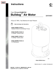
1
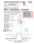
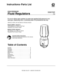
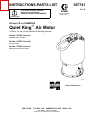
INSTRUCTIONS-PARTS LIST
This manual contains important
warnings and information.
READ AND KEEP FOR REFERENCE.
307741
Rev. R
First choice when
quality counts.t
INSTRUCTIONS
255 mm (10 in.) DIAMETER
Quiet KingR Air Motor
0.6 MPa, 6.2 bar (90 psi) Maximum Working Pressure
Part No. 220106, Series A
Standard Quiet Air Motor
Part No. 235525, Series B
Quiet Air Motor
Part No. 237000, Series A
Reduced Icing Quiet Air Motor
03695A
Model 220106 Shown
GRACO INC.
P.O. BOX 1441
MINNEAPOLIS, MN
ECOPYRIGHT 1985, GRACO INC.
Graco Inc. is registered to I.S. EN ISO 9001
55440–1441
Table of Contents
Warnings . . . . . . . . . . . . . . . . . . . . . . . . . . . . . . . . . . . . . . 2
Installation . . . . . . . . . . . . . . . . . . . . . . . . . . . . . . . . . . . . . 5
Troubleshooting . . . . . . . . . . . . . . . . . . . . . . . . . . . . . . . . 7
Service . . . . . . . . . . . . . . . . . . . . . . . . . . . . . . . . . . . . . . 10
Parts . . . . . . . . . . . . . . . . . . . . . . . . . . . . . . . . . . . . . . . . 18
Dimensions . . . . . . . . . . . . . . . . . . . . . . . . . . . . . . . . . . . 24
Technical Data . . . . . . . . . . . . . . . . . . . . . . . . . . . . . . . . 25
Warranty . . . . . . . . . . . . . . . . . . . . . . . . . . . . . . . . . . . . . 28
Graco Phone Number . . . . . . . . . . . . . . . . . . . . . . . . . . 28
Symbols
Warning Symbol
WARNING
This symbol alerts you to the possibility of serious
injury or death if you do not follow the instructions.
Caution Symbol
CAUTION
This symbol alerts you to the possibility of damage to
or destruction of equipment if you do not follow the
instructions.
WARNING
EQUIPMENT MISUSE HAZARD
Equipment misuse can cause the equipment to rupture or malfunction and result in serious injury.
INSTRUCTIONS
D This equipment is for professional use only.
D Read all instruction manuals, tags, and labels before operating the equipment.
D Use the equipment only for its intended purpose. If you are uncertain about usage, call your Graco
distributor.
D Do not alter or modify this equipment. Use only genuine Graco parts and accessories.
D Check equipment daily. Repair or replace worn or damaged parts immediately.
D Do not exceed the maximum working pressure stated on the equipment or in the Technical Data
for your equipment. Do not exceed the maximum working pressure of the lowest rated component
in your system.
D Use fluids and solvents which are compatible with the equipment wetted parts. Refer to the Technical Data section of all equipment manuals. Read the fluid and solvent manufacturer’s warnings.
D Do not use hoses to pull equipment.
D Route hoses away from traffic areas, sharp edges, moving parts, and hot surfaces. Do not expose
Graco hoses to temperatures above 82_C (180_F) or below –40_C (–40_F).
D Wear hearing protection when operating this equipment.
D Do not lift pressurized equipment.
D Do not lift the equipment by the air motor lift ring if the total weight of the equipment exceeds 550 lb
(250 kg).
D Comply with all applicable local, state, and national fire, electrical, and safety regulations.
2
307741
WARNING
INJECTION HAZARD
Spray from the gun/valve, hose leaks, or ruptured components can inject fluid into your body and
cause extremely serious injury, including the need for amputation. Fluid splashed in the eyes or on the
skin can also cause serious injury.
D Fluid injected into the skin might look like just a cut, but it is a serious injury. Get immediate medical attention.
D Do not point the gun/valve at anyone or at any part of the body.
D Do not put your hand or fingers over the spray tip/nozzle.
D Do not stop or deflect leaks with your hand, body, glove or rag.
D Do not “blow back” fluid; this is not an air spray system.
D Always have the tip guard and the trigger guard on the gun when spraying.
D Check the spray gun diffuser operation weekly. Refer to the gun manual.
D Be sure the gun/valve trigger safety operates before spraying/dispensing.
D Lock the gun/valve trigger safety when you stop spraying/dispensing.
D Follow the Pressure Relief Procedure on page 7 whenever you: are instructed to relieve pressure; stop spraying/dispensing; clean, check, or service the equipment; and install or clean the
spray tip/nozzle.
D Tighten all fluid connections before operating the equipment.
D Check the hoses, tubes, and couplings daily. Replace worn, damaged, or loose parts immediately.
Permanently coupled hoses cannot be repaired; replace the entire hose.
D Use only Graco approved hoses. Do not remove any spring guard that is used to help protect the
hose from rupture caused by kinks or bends near the couplings.
MOVING PARTS HAZARD
Moving parts, such as the air motor piston, can pinch or amputate your fingers.
D Keep clear of all moving parts when starting or operating the pump.
D Before servicing the equipment, follow the Pressure Relief Procedure on page 7 to prevent the
equipment from starting unexpectedly.
307741
3
WARNING
FIRE AND EXPLOSION HAZARD
Improper grounding, poor ventilation, open flames or sparks can cause a hazardous condition and
result in a fire or explosion and serious injury.
D Ground the equipment and the object being sprayed. Refer to Grounding on page 5.
D If there is any static sparking or you feel an electric shock while using this equipment, stop spraying/dispensing immediately. Do not use the equipment until you identify and correct the problem.
D Provide fresh air ventilation to avoid the buildup of flammable fumes from solvents or the fluid
being sprayed/dispensed.
D Keep the spray/dispense area free of debris, including solvent, rags, and gasoline.
D Electrically disconnect all equipment in the spray/dispense area.
D Extinguish all open flames or pilot lights in the spray/dispense area.
D Do not smoke in the spray/dispense area.
D Do not turn on or off any light switch in the spray/dispense area while operating or if fumes are
present.
D Do not operate a gasoline engine in the spray/dispense area.
TOXIC FLUID HAZARD
Hazardous fluid or toxic fumes can cause serious injury or death if splashed in the eyes or on the skin,
inhaled, or swallowed.
D Know the specific hazards of the fluid you are using.
D Store hazardous fluid in an approved container. Dispose of hazardous fluid according to all local,
state and national guidelines.
D Always wear protective eyewear, gloves, clothing and respirator as recommended by the fluid and
solvent manufacturer.
4
307741
Installation
General Information
NOTE: Reference numbers and letters in parentheses
in the text refer to the callouts in the figures and the
parts drawing.
NOTE: Always use Genuine Graco Parts and Accessories, available from your Graco distributor.
Grounding
WARNING
FIRE AND EXPLOSION HAZARD
Before operating the pump, ground the
system as explained below. Also read
the section FIRE AND EXPLOSION
HAZARD on page 4.
1. Pump: Use a ground wire and clamp as shown in
Fig. 1. Loosen the grounding lug locknut (W) and
washer (X). Insert one end of a 12 ga (1.5 mm@)
minimum ground wire (Y) into the slot in lug (Z)
and tighten the locknut securely. Connect the other
end of the wire to a true earth ground. Order part
number 237569 Grounding Clamp and Wire.
4. Spray gun or dispensing valve: Ground through
connection to a properly grounded fluid hose and
pump.
5. Object being sprayed: Follow your local code.
6. Fluid supply container: Follow your local code.
7. Solvent pails used when flushing: Follow your local
code. Use only metal pails, which are conductive,
placed on a grounded surface. Do not place the
pail on a nonconductive surface, such as paper or
cardboard, which interrupts the grounding continuity.
8. To maintain grounding continuity when flushing or
relieving pressure, hold a metal part of the spray
gun/dispense valve firmly to the side of a grounded
metal pail, then trigger the gun/valve.
Z
X
W
Y
2. Air and fluid hoses: Use only electrically conductive hoses.
3. Air compressor: Follow manufacturer’s recommendations.
Fig. 1
307741
5
Installation
Noise Reduction
Instruction Manual 307375 is supplied with this motor.
It provides information on noise reduction.
The following are additional recommendations for
Maximum Noise Reduction:
D The air line should be connected to the air motor
inlet with an electrically conductive flexible hose.
Also, use flexible fluid outlet and suction hoses.
Where possible, avoid using solid plumbing, which
carries noise vibrations.
D Mount the air motor on resilient rubber pads, rather
than sheet metal.
D Determine minimum air inlet pressure and pump
cycle rate to achieve desired spray/dispensing
results or minimum fluid pressure and flow. This will
result in less system wear and less overall noise.
6
307741
Air Motor Icing
Moisture in the compressed air can collect in the air
motor and freeze, causing the motor to stall. This is
called icing. If icing occurs, shut off the air supply and
allow the ice to thaw.
To minimize icing, reduce the moisture in your compressed air supply by using an air dryer or a filter
which traps water.
Slope the main air line slightly downward so water will
collect at the end of the line, where it can be drained.
Additionally, plumb each drop line from the top of the
main air line. Install an automatic drain or a drain valve
at the bottom of each drop.
Model 237000 Reduced Icing Air Motor allows you to
divert a stream of air over the air valves. This flow of
warm air prevents water from collecting and freezing.
The amount of air is adjustable with a needle valve
(88, see the parts drawing on page 22).
For additional help in designing your system, contact
your Graco distributor.
Troubleshooting
Pressure Relief Procedure
WARNING
INJECTION HAZARD
To reduce the risk of serious injury, including fluid injection, splashing in the
eyes or on the skin, or moving parts,
always follow the Pressure Relief Procedure
whenever you
D
D
D
D
D
are instructed to relieve the pressure
shut off the pump
stop spraying/dispensing
check or service any of the system equipment
install or clean the spray tips/nozzles
1. Lock the gun/valve trigger safety.
Stalled Motor
To restart a stalled motor, close the bleed-type master
air valve to bleed off all trapped air pressure. Turn the
air back on. This will trip the air valve of the air motor,
causing the piston to go to the top or bottom of its
stroke.
WARNING
MOVING PARTS HAZARD
The piston in the air motor moves when
air is supplied to the motor. Moving parts
can pinch or amputate your fingers or
other body parts. Relieve the pressure before
servicing the motor.
2. Turn off the air to the motor.
3. Close the bleed-type master air valve (required in
your system).
4. Unlock the gun/valve trigger safety. Hold a metal
part of the gun/valve firmly to a grounded metal
pail. Trigger the gun/valve to relieve pressure.
5. Lock the gun/valve trigger safety.
6. Open the fluid drain valve. Leave the fluid drain
valve open until you are ready to spray/dispense
again.
If you suspect that the spray tip/nozzle or hose is
completely clogged, or that pressure has not been fully
relieved after following the steps above, very slowly
loosen the tip guard retaining nut or hose end coupling
to relieve pressure gradually, then loosen completely.
Now clear the tip/nozzle or hose obstruction.
If Motor Will Not Operate
Check the following areas for damage or wear and
replace parts as needed.
Air valving mechanism: director valve (3), spring (4),
air valve housing (5), valve plate (2), valve plate seal
(1).
Trip rod: check for broken spring or bent rod (40). Do
not attempt to repair the trip rod.
Damaged toggle mechanism: guide (16), spring (17),
housing (18), pin (19).
307741
7
Troubleshooting
Air Leaks
Air leaks are caused by worn or damaged gaskets or
seals. To locate the leaks, first shut off the air supply to
the pump and open the bleed-type master air valve to
relieve air pressure. Disconnect the main air supply
line from the air inlet. Remove the shield (27) as
explained on page 10, then reinstall the other parts
and connect the main air line to the inlet.
Open the bleed-type master air valve and adjust the air
pressure to .07–0.1 MPa, 0.7–1.0 bar (10–15 psi). Stall
the pump on both the up and down stroke as indicated
in the Check Chart below. Use the methods listed in
the Check Chart to find where air is leaking. See Fig.
2.
WARNING
MOVING PARTS HAZARD
Keep you fingers away from all moving
parts while performing this test, to
reduce the risk of pinching or amputating
your fingers. Reinstall the air motor shield before
resuming normal operation of the pump.
Check for air leaks by feeling, listening, or squirting oil
around the suspected area. The oil will bubble if there
is a leak.
CHECK CHART
Stroke Position
Letter Ref. Points
Check Method
Cause of Leakage
UP stroke only
F
By listening for air leak at
exhaust outlets
Worn trip rod packing (65).
B
By feel
Blown air cylinder gasket
(35).
C
Squirt oil around wiper (44) Worn throat packing (46).
G
By feel
Damaged cylinder gasket
(38).
DOWN stroke only
D
By feel.
Damaged air manifold gasket (30).
BOTH strokes
E
By feeling exhaust, or
hearing a high-pitched
sound
Worn director valve (3).
Replace, or lap faces with
no. 500 grit sandpaper.
F
By feel, or hearing a highpitched sound
Worn piston o-ring (33).
D or G
By feel
Blown manifold gaskets
(38 and 30).
H
Squirt oil around o-ring
(15)
Damaged housing o-ring
(15).
K
By feel
Damaged o-ring (26).
8
307741
Troubleshooting
1
Pack cavity with light
waterproof grease.
2
Grease packing (46*).
3
Lips of packing (46*)
must face up.
K (26)
29
D (30*)
H (15)
E (3)
G (38*)
*65
F (33*)
B (*35)
C (44*)
*45, *46
1
2
3
03705A
Model 220106 Shown
Fig. 2
307741
9
Service
b. For Model 237000: See page 22. Remove the
lift ring (25), o-ring (26), screws (24), lockwashers (23), air inlet fitting (68), and mufflers
(76). Remove the air tube (83) from the fitting
(87) and push it down through the grommet
(81). Remove the shield (27).
WARNING
To avoid serious injury and equipment
damage, do not lift the equipment by the
air motor lift ring if the total weight of the
equipment exceeds 550 lb (250 kg). The
lift ring cannot support that weight.
Tools Required
D Padded pliers, Part No. 207579 (for use on trip
rod).
D Torque wrench
4. Remove the gasket (53). Lift off the manifold cap
(29). Remove the gasket (30).
5. Unscrew the toggle retainers (14), and remove the
o-rings (15), housing guides (16), springs (17),
housings (18), and pins (19) from each side of the
manifold (20).
D 1 in. deep well socket wrench
D Set of socket or box wrenches
25
D Adjustable wrench
32
68
24
D O-ring pick
26
D Light waterproof grease
D Loctiter 242 or equivalent
67
23
21
Disassembly
NOTE: Repair Kit 220153 is available. Parts included
are marked with an asterisk, for example (30*). For the
best results, use all the new parts in the kit.
27
NOTE: Inspect all parts as they are disassembled and
replace worn or damaged parts.
53
29
WARNING
30
To reduce the risk of serious injury whenever you
are instructed to relieve pressure, always follow the
Pressure Relief Procedure on page 7.
18
19
1. Relieve the pressure.
16
2. Disconnect the air hose from the air inlet swivel
(68). Disconnect the displacement pump from the
motor.
20
15
17
14
NOTE: Refer to Fig. 3 for steps 3 to 5.
3. To remove the shield, perform step a or b, as
applicable.
a. For Models 220106 and 235525: Remove the
lift ring (25), o-ring (26), screws (24), lockwashers (23), air inlet assembly, and shield
(27). See Fig. 3.
10 307741
Model 220106 Shown
Fig. 3
07281A
Service
NOTE: Refer to Fig. 4 for steps 6 to 11.
6. Remove the screws (31) and lockwashers (13)
from the manifold (20).
7. To prevent the spring-loaded director valves
(3) from popping out, carefully lift the manifold
(20) up about 51 mm (2 in.) from the cylinder (36).
Place one hand under the manifold to hold the
director valves in the valve housing (5), then
continue lifting the manifold. Remove your hand
slowly, allowing the valve springs to release gently.
Inspect the director valves (3) and compression
springs (4).
8. Turn the manifold (20) over. Place wrenches on
the flats of the adjusting screw (11) and nut (12)
and turn the screw further into the nut until you can
remove it. Do this in all four positions.
WARNING
The openings in the valve plates (2) are very sharp.
Be careful not to cut yourself.
20
9. Remove and check the valve plates (2), handling
them carefully. Clean the plates and mating surfaces of the manifold (20). Remove the rubber pad
(8).
NOTE: If you replace the valve plates, also replace the
seals (1).
CAUTION
Be careful not to damage the surface of the trip rod
(40), which would restrict its free movement. Special
padded pliers, 207579, are available.
10. Pull the trip rod (40) up and grasp it with the
padded locking pliers (order 207579). Hold the
flats of the valve housing hub (10) with a wrench,
screw off the trip rod nut (7) and remove the air
valve housing (5). Remove the lockwasher (6) and
screw off the hub (10). Now release the pliers.
11. Remove the gasket (38) from the air cylinder (36).
31
13
7
6
Detail of Air Manifold and Valve Plates
5
20
4
3
3
8
4
40
2
10
38
1
1
2
12
11
36
07282A
Fig. 4
307741
11
Service
NOTE: Refer to Fig. 5 for steps 12 to 18.
12. Remove the rubber pad (8) from the cylinder (36).
Remove the trip rod bearing (37), using a 1 in.
deep-well socket wrench. Remove the gasket (66),
v-block packing (65), and backup washer (64) from
the bearing.
CAUTION
Be careful not to tilt the cylinder when removing it
from the piston to avoid damaging the smooth inner
surface of the cylinder.
13. Remove the screws (31) and lockwashers (13) and
carefully pull the cylinder straight up off the piston
(34).
CAUTION
Be careful not to damage the polished surface of the
piston shaft.
15. Lock the hex of the piston shaft (34) in a vise and
unscrew the connecting rod stud (39) from the
piston shaft.
CAUTION
Handle the trip rod assembly (40) carefully. Nicks
and scratches cause premature spring failure.
NOTE: A damaged trip rod cannot be repaired; use a
new one.
16. Remove the trip rod (40) from the piston (34).
14. Pull the piston (34) and trip rod (40) up out of the
base (47). Remove the o-ring (33) from the piston.
17. Remove the v-block packing (46), backup washer
(45), o-ring (41), and gasket (35) from the base
(47).
NOTE: The connecting rod stud (39) is fastened to the
piston shaft (34) with anaerobic sealant, and may be
difficult to remove.
18. Turn the base over and remove the wiper seal
(44). Inspect the bearing (70) in place. Remove
only if damaged.
12 307741
Service
8
37
66
64
65
40
36
34
34
33
47
13
31
40
07283A
39
35
03701
47
46
45
41
70
44
07421A
Fig. 5
307741
13
Service
Reassembly
1. Clean all parts thoroughly and inspect for wear or
damage. Replace parts as necessary.
NOTE: Refer to Fig. 6 for steps 2 to 5.
2. Turn the base (47) upside down. If the bearing (70)
was removed, press-fit the new bearing so its top
edge is flush with the shoulder (S) of the packing
cavity. After installation, measure the inner diameter of the bearing. It must be uniformly 35 mm
(1.375 in.) to ensure that the piston shaft does not
bind. If incorrect, size the bearing while in place;
this can be done with a 35 mm (1.375 in.) diameter
steel ball.
3. Grease the wiper seal (44*) and press-fit in the
base (47).
4. Turn the base upright. Install the backup washer
(45*) in the base (47). Grease the v-block packing
(46*) and install it in the base so the lips face up.
5. Place the o-ring (41) onto the air motor base (47).
Place the gasket (35*) on the base so one of its
notches (K) aligns with the optional fluid outlet (L).
1
Inner diameter of the bearing must be uniformly 35 mm (1.375 in.).
2
Grease.
3
Lips of packing must face up.
4
Align notch (K) in gasket (35) with the optional fluid outlet (L) in the base (47).
35*
S
K
4
46*
2
3
45*
47
41
70
1
44*
2
L
4
07421A
Fig. 6
14 307741
Service
NOTE: Refer to Fig. 7 for steps 6 to 10.
6. Grease the trip rod (40) with light, water-proof
grease and slide it into the piston (34) shaft. Clean
the threads of the piston and the connecting rod
stud (39). Apply LoctiteR 242 or the equivalent to
both. Screw the stud into the piston and torque it
to 200–220 NSm (148–162 ft-lb).
7. Place the cylinder (36) upside down on the base
(47). Grease the piston (34), o-ring (33*), and
inside of the cylinder. Place the o-ring around the
piston; the o-ring is larger than the piston groove.
Install the piston in the cylinder so the excess of
the o-ring fits into one of the air channels (M) of
the cylinder. Use your fingers to push the o-ring
out of the channel and seat it in the piston groove.
Very carefully lower the piston into the cylinder.
8. Regrease the inside of the cylinder (36). Carefully
turn the piston assembly and cylinder over and
guide it into the base (47). Align one of the cylinder’s air channels (M) with the notch (K) in the
gasket (35) and with the optional fluid outlet (L) of
the base. Install the lockwashers (13) and screws
(31) and torque to 34 NSm (25 ft-lb).
9. Install the backup washer (64*) and v-block packing (65*) in the bearing (37) so the lips of the
packing face out of the bearing. Install the gasket
(66) on the bearing. Grease the trip rod (40) and
thread the bearing onto the trip rod and into the
cylinder (36). Use a 1 in. deep-well socket wrench
to tighten the bearing.
10. Install the rubber pad (8) in the cylinder (36).
1
Grease with light, waterproof grease.
5
Torque to 34 NSm (25 ft–lb).
2
Apply Loctiter 242 or equivalent to threads.
6
Lips must face down, out of bearing (37).
3
Torque to 200–220 NSm (148–162 ft-lb).
7
Align air channel (M) and notch (K) in gasket (35)
with the optional fluid outlet (L) in the base (47).
4
Grease inside wall of cylinder.
8
34
37
1
66
33*
64*
65*
1
6
40
4
36
2
34
40
1
47
M
7
K
7
13
31
39
2
5
3
03701
L
7
07283A
Fig. 7
307741
15
Service
NOTE: Refer to Fig. 8 for steps 11 to 16.
15. Install the rubber pad (8) in the air manifold (20).
11. Place the gasket (38*) on top of the cylinder (36).
12. Thread the hub (10) onto the trip rod (40). Lift the
rod and grasp it with the padded locking pliers.
Screw the hub down as far as possible by hand.
13. Install the air valve housing (5), lockwasher (6),
and trip rod nut (7) so the nut is flush with the top
of the trip rod (40). Tighten the nut 2 turns more,
so there is 1 mm (0.04 in.) clearance between the
top of the rod and the top of the nut. Hold the flats
of the trip rod nut with a wrench. With another
wrench, tighten the hub (10) to 28–34 NSm (21–25
ft-lb). Release the pliers.
14. Place the plate seals (1) on the valve plates (2).
Place the plates in the air manifold (20). Install the
adjusting screw (11) and nut (12) assemblies in all
four corners of the plates. Important: Adjust the
screws and nuts evenly so they snugly hold the
plates. Do not exceed 4 NSm (35 in-lb).
NOTE: On Model 235525, check that the plugs (9) are
in place in the air manifold exhaust ports (E).
On Model 237000, check that the tubing (82) is securely attached to the air manifold (20). See page 22.
16. Place the springs (4) and air director valves (3)
into the valve housing (5). Hold the springs and
valves in place and install the air manifold (20)
over the housing, making sure it is properly oriented. The exhaust ports (E) must be oriented to
the optional outlet (L) of the base as shown. Be
sure the valve housing (5) moves up and down
freely, and then install and tighten the screws (31)
and lockwashers (13) holding the manifold (20) to
the cylinder (36).
Detail of Air Manifold and Valve Plates
31
20
20
13
8
7
6
E
5
2
1
2
4
3
Detail of Valve Housing
1
4
3
12
11
3
40
7
4
1
40
10
5
38*
C
1
Make top of nut flush with top of trip
rod, then tighten 2 turns more.
Top of nut (7) must be 1 mm (0.04”)
from end of rod (40).
2
Torque to 28–34 NSm (21–25 ft-lb)
3
Tighten snugly. Do not exceed 4 NSm (35 in-lb).
4
Torque to 34 NSm (25 ft-lb).
2
36
02963
07282A
Fig. 8
16 307741
L
Service
NOTE: Refer to Fig. 9 for steps 17 to 22.
17. Lubricate the housing (18), spring (17), and guide
(16) with light, water-proof grease. Assemble the
housing and spring into the guide. Lubricate the
pin (19) and slide it into the housing. Slide these
assembled parts into the air manifold (20). Be sure
the pin (19) is aligned with the slot (C, Fig. 8) of
the air valve housing (5) before assembling the
rest of the air valve. Repeat for the other side.
18. Install the o-ring (15) on the retainer (14). Screw
the retainers into both sides of the manifold (20);
they should readily screw all the way into the
manifold by hand. If they do not, the parts are not
assembled correctly; inspect, and correct any
misalignment. Now firmly tighten the retainers
(14).
22. Reconnect the motor to the displacement pump,
remount the pump and connect the air and fluid
lines. Reconnect the ground wire before operating
the pump.
1
Grease with light, waterproof grease.
2
Torque to 12–16 NSm (9–12 ft-lb).
67
32
25
24
2
68
26
23
21
19. Place the gasket (30*), cap (29), and gasket (53)
on the air manifold (20). Check the parts list for
your model for the correct gasket (30*) to use. Be
sure these parts are oriented as shown in the parts
drawing for your model.
27
WARNING
MOVING PARTS HAZARD
Do not operate without the air motor
shield in place. Pinching or amputation
of fingers or hands may occur. See
MOVING PARTS HAZARD on page 3.
53
29
*30
20. To install the shield (27), perform step a or b, as
applicable.
a. For Models 220106 and 235525: Install the
o-ring (26), lift ring (25), screws (24), lockwashers (23), air inlet assembly, and shield
(27). Torque the screws to 12–16 NSm (9–12
ft-lb).
b. For Model 237000: See page 22. Thread the
tube (83) through the grommet (81) in the
shield (27) as much as possible. Install the
shield. Install the o-ring (26), lift ring (25),
screws (24), lockwashers (23), air inlet fitting
(68), and mufflers (76). Torque the screws to
12–16 NSm (9–12 ft-lb). Connect the tube (83)
to the fitting (87).
21. Test the motor at 0.1–0.2 MPa, 1–2 bar (15–30
psi) before reconnecting to the pump, to be sure it
operates properly.
1
1
1
4
16
20
18
19
1
17
15
Model 220106 Shown
07281A
Fig. 9
307741
17
Parts
Model 220106, Series A
Standard Quiet Air Motor
25
67
24
32
68
26
36
23
21
69
27
72Y
71Y
35*
28
33*
53
34
29
*30
20
31
13
19
18
17
16
15
40
14
8
7
6
39
5
4
3
12 11
10
*38
46*
45*
41
2
1
47
8
37
13
31
66
*64
62
63
*65
43
70
44*
03696A
18 307741
Parts
Model 220106, Series A
Standard Quiet Air Motor
Ref
No.
Part No.
1
2
3n
4
5n
6
7
8n
10
11
12
13
14
15n
16n
17n
18n
19n
20
21
168184
176536
176518
176543
176519
105319
176569
176549
176568
176550
176548
100018
178428
105318
178427
178429
178426
105321
181322
100549
23
24
104572
105322
25
26n
27
28
29
30*
31
176537
166221
181276
181308
181321
181323
105324
32
33*
34
35*
36
166466
102727
220105
168189
181297
Description
SEAL, plate
PLATE, valve
VALVE, director
SPRING, compression
HOUSING, air valve
LOCKWASHER; 10 mm
NUT, trip rod
PAD, rubber
HUB, valve housing
SCREW, adjusting
NUT, adjusting
LOCKWASHER
RETAINER, toggle
O-RING; nitrile rubber
GUIDE, housing
SPRING, compression
HOUSING, spring
PIN, dowel
MANIFOLD, air
ELBOW, pipe, 90_ street;
3/4 npt (m x f)
LOCKWASHER; 8 mm
CAPSCREW, hex hd;
M8 x 1.5 x 100
RING, lift
O-RING; nitrile rubber
SHIELD
INSULATION
CAP, manifold
GASKET; cellulose fibre
CAPSCREW, hex hd;
M12 x 1.75 x 30
TEE, pipe; 3/4 npt(f)
O-RING; nitrile rubber
PISTON ASSEMBLY
GASKET; buna-N/cellulose
CYLINDER
Qty
2
2
2
2
1
1
1
2
1
4
4
4
2
2
2
2
2
2
1
1
8
8
1
1
1
2
1
1
16
1
1
1
1
1
Ref
No.
Part No.
37n
38*
39
40n
41n
43
44*
45*
46*
47
215933
176575
176564
218597
102737
102725
161569
161563
161562
235844
53n
62
63
64*
65*
66n
67
68
177081
104582
104029
161559
161560
150647
108307
157785
69
214953
70
71Y
72Y
189059
290331
189991
*
Description
Qty
BEARING, trip rod
GASKET; cellulose fibre
STUD, connecting rod
TRIP ROD ASSY
O-RING; buna-N
PLUG, pipe
SEAL, wiper
WASHER, backup
V-PACKING; nitrile rubber
AIR MOTOR BASE ASSY
includes item 70
GASKET; neoprene
WASHER, tab
CLAMP, grounding
WASHER, backup
V-PACKING; polyurethane
GASKET; copper
ELBOW, pipe, 90_; 3/4 npt(mbe)
UNION, swivel; 3/4 nps(f) swivel x
3/4 npt(m)
HOSE, air; buna-N; 3/4” ID; cpld
3/4 npt(mbe); 1.25’ (381 mm)
BEARING
LABEL, warning; English
LABEL, warning
1
1
1
1
1
1
1
1
1
1
1
1
1
1
1
1
1
2
1
1
1
1
These parts are included in Repair Kit 220153,
which may be purchased separately.
n Keep these spare parts on hand to reduce down
time.
Y Replacement Danger and Warning labels, tags and
cards are available at no cost. The 290331 label is
also available in the following languages:
German (Part No. 290396)
French (Part No. 290397)
Spanish (Part No. 290398).
307741
19
Parts
Model 235525, Series B
Quiet Air Motor
25
68
36
24
26
23
27
72Y
71Y
35*
28
33*
34
53
29
*30
20
31
19
13
18
17
16
15
40
9
14
8
7
6
39
5
4
3
12 11
10
46*
45*
41
2
1
*38
47
8
37
13
31
62
63
66
*64
*65
43
70
44*
03698A
20 307741
Parts
Model 235525, Series B
Quiet Air Motor
Ref
No.
Part No.
1
2
3n
4
5n
6
7
8n
9
10
11
12
13
14
15n
16n
17n
18n
19n
20
23
24
168184
176536
176518
176543
176519
105319
176569
176549
100361
176568
176550
176548
100018
178428
105318
178427
178429
178426
105321
176540
104572
105322
25
26n
27
28
29
30*
31
176537
166221
181276
181308
176539
176580
105324
33*
34
35*
36
102727
220105
168189
181297
Description
SEAL, plate
PLATE, valve
VALVE, director
SPRING, compression
HOUSING, air valve
LOCKWASHER; 10 mm
NUT, trip rod
PAD, rubber
PLUG, pipe
HUB, valve housing
SCREW, adjusting
NUT, adjusting
LOCKWASHER
RETAINER, toggle
O-RING; nitrile rubber
GUIDE, housing
SPRING, compression
HOUSING, spring
PIN, dowel
MANIFOLD, air
LOCKWASHER; 8 mm
CAPSCREW, hex hd;
M8 x 1.5 x 100
RING, lift
O-RING; nitrile rubber
SHIELD
INSULATION
CAP, manifold
GASKET; cellulose fibre
CAPSCREW, hex hd;
M12 x 1.75 x 30
O-RING; nitrile rubber
PISTON ASSEMBLY
GASKET; buna-N/cellulose
CYLINDER
Qty
2
2
2
2
1
1
1
2
2
1
4
4
4
2
2
2
2
2
2
1
8
8
1
1
1
2
1
1
16
1
1
1
1
Ref
No.
Part No.
37n
38*
39
40n
41n
43
44*
45*
46*
47
215933
176575
176564
218597
102737
102725
161569
161563
161562
235844
53n
62
63
64*
65*
66n
68
177081
104582
104029
161559
161560
150647
207648
70
71Y
72Y
189059
290331
189991
*
Description
Qty
BEARING, trip rod
GASKET; cellulose fibre
STUD, connecting rod
TRIP ROD ASSY
O-RING; buna-N
PLUG, pipe
SEAL, wiper
WASHER, backup
V-PACKING; nitrile rubber
AIR MOTOR BASE ASSY
includes item 70
GASKET; neoprene
WASHER, tab
CLAMP, grounding
WASHER, backup
V-PACKING; polyurethane
GASKET; copper
ADAPTER, swivel; 3/4 npt(m) x
3/4 npsm(f)
BEARING
LABEL, warning; English
LABEL, warning
1
1
1
1
1
1
1
1
1
1
1
1
1
1
1
1
1
1
1
1
These parts are included in Repair Kit 220153,
which may be purchased separately.
n Keep these spare parts on hand to reduce down
time.
Y Replacement Danger and Warning labels, tags and
cards are available at no cost. The 290331 label is
also available in the following languages:
German (Part No. 290396)
French (Part No. 290397)
Spanish (Part No. 290398).
307741
21
Parts
Model 237000, Series A
Reduced Icing Quiet Air Motor
68
24
88
25
87
83
26
36
23
81
27
76
77
78
35*
82
79
Y72
Y71
33*
53
34
83
29
69
86
*30
85
84
31
19
40
13
80, 81
18
20
17
16
82
15
8
7
6
5
14
39
46*
45*
3
10
41
4
2
1
12 11
47
*38
8
13
31
37
66
62
63
*64
*65
43
70
44*
07420A
22 307741
Parts
Model 237000, Series A
Reduced Icing Quiet Air Motor
Ref
No.
Part No.
1
2
3n
4
5n
6
7
8n
10
11
12
13
14
15n
16n
17n
18n
19n
20
23
24
168184
176536
176518
176543
176519
105319
176569
176549
176568
176550
176548
100018
178428
105318
178427
178429
178426
105321
181322
104572
105322
25
26n
27
29
30*
31
176537
166221
112736
189985
112741
105324
33*
34
35*
36
37n
38*
39
40n
41n
43
44*
45*
46*
102727
220105
168189
181297
215933
176575
176564
218597
102737
102725
161569
161563
161562
Description
SEAL, plate
PLATE, valve
VALVE, director
SPRING, compression
HOUSING, air valve
LOCKWASHER; 10 mm
NUT, trip rod
PAD, rubber
HUB, valve housing
SCREW, adjusting
NUT, adjusting
LOCKWASHER
RETAINER, toggle
O-RING; nitrile rubber
GUIDE, housing
SPRING, compression
HOUSING, spring
PIN, dowel
MANIFOLD, air
LOCKWASHER; 8 mm
CAPSCREW, hex hd;
M8 x 1.5 x 100
RING, lift
O-RING; nitrile rubber
SHIELD
CAP, manifold
GASKET; cellulose fibre
CAPSCREW, hex hd;
M12 x 1.75 x 30
O-RING; nitrile rubber
PISTON ASSEMBLY
GASKET; buna-N/cellulose
CYLINDER
BEARING, trip rod
GASKET; cellulose fibre
STUD, connecting rod
TRIP ROD ASSY
O-RING; buna-N
PLUG, pipe
SEAL, wiper
WASHER, backup
V-PACKING; nitrile rubber
Qty
2
2
2
2
1
1
1
2
1
4
4
4
2
2
2
2
2
2
1
8
8
1
1
1
1
1
16
1
1
1
1
1
1
1
1
1
1
1
1
1
Ref
No.
Part No.
47
235844
53n
62
63
64*
65*
66n
68
112740
104582
104029
161559
161560
150647
189986
69
70
71Y
72Y
76
77
78
79
80
81
82
102726
189059
290331
189991
111897
112885
801523
112739
109018
112738
190009
83
190010
84
85
86
112735
105912
112117
87
88
104172
203743
*
Description
Qty
AIR MOTOR BASE ASSY
includes item 70
1
GASKET; neoprene
1
WASHER, tab
1
CLAMP, grounding
1
WASHER, backup
1
V-PACKING; polyurethane
1
GASKET; copper
1
AIR INLET FITTING; 3/4 npt(m) x
3/4 npt(f) swivel x 1/8 npt(f)
1
PLUG, pipe; 1” npt
1
BEARING
1
LABEL, warning; English
1
LABEL, warning
1
MUFFLER
2
ELBOW; 1” x 1/2 npt (fbe)
2
ADAPTER; 1/2 npt x 1/2 btp (mbe) 2
TEE; 1/4” (6 mm) OD tube
1
O-RING; nitrile
2
GROMMET
3
TUBE; nylon; 1/4” (6 mm) OD;
8” (203 mm) long
2
TUBE; nylon; 1/4” (6 mm) OD;
21” (533 mm) long
1
BRACKET
2
NUT, hex; M6 x 1
2
SCREW, cap, hex hd; M6 x 1.0;
16 mm (5/8”) long
2
FITTING, tube; 1/8 npt(m)
1
VALVE, needle
1
These parts are included in Repair Kit 220153,
which may be purchased separately.
n Keep these spare parts on hand to reduce down
time.
Y Replacement Danger and Warning labels, tags and
cards are available at no cost. The 290331 label is
also available in the following languages:
German (Part No. 290396)
French (Part No. 290397)
Spanish (Part No. 290398).
307741
23
Dimensions
Models 220106 (shown) and 235525
Model 237000
3/4 npt(f) Swivel
Air Inlet
3/4 npsm(f) Swivel
Air Inlet
546 mm
(21.50”)
546 mm
(21.50”)
16 Exhaust Holes.
Plug when exhausting to
outside or through muffler
1–1/4 npt Exhaust Port
Maximum Diameter: 305 mm (12”)
94 mm
(3.712”)
88 mm
(3.464”)
03695
03697
102 mm (4”)
5/8–11 unc (3) for
pump attachment
51 mm (2”)
11.1 mm (0.437”)
Diameter (4)
94 mm
(3.712”)
BOTTOM VIEW
24 307741
03702
Technical Data
Category
Data
Maximum Incoming Air Pressure
0.6 MPa, 6.2 bar (90 psi)
Effective Piston Area
506 cm@ (78.5 sq. in.)
Piston Diameter
255 mm (10 in.)
Stroke Length
121 mm (4.75 in.)
Air Valves
stainless steel plate; sliding acetal ring
Recommended maximum speed
50 cycles per minute
Weight
34 kg (75 lb)
Air inlet
3/4 npsm
Loctiter is a registered trademark of the Loctite Corporation.
Manual Change Summary
Correction to Model 237000: Part number 190010 (83) was 109010.
307741
25
Notes
26 307741
Notes
307741
27
The Graco Standard Warranty
Graco warrants all equipment manufactured by Graco and bearing its name to be free from defects in material and workmanship on the
date of sale by an authorized Graco distributor to the original purchaser for use. With the exception of any special, extended, or limited
warranty published by Graco, Graco will, for a period of twelve months from the date of sale, repair or replace any part of the equipment
determined by Graco to be defective. This warranty applies only when the equipment is installed, operated and maintained in accordance with Graco’s written recommendations.
This warranty does not cover, and Graco shall not be liable for general wear and tear, or any malfunction, damage or wear caused by
faulty installation, misapplication, abrasion, corrosion, inadequate or improper maintenance, negligence, accident, tampering, or substitution of non–Graco component parts. Nor shall Graco be liable for malfunction, damage or wear caused by the incompatibility of
Graco equipment with structures, accessories, equipment or materials not supplied by Graco, or the improper design, manufacture,
installation, operation or maintenance of structures, accessories, equipment or materials not supplied by Graco.
This warranty is conditioned upon the prepaid return of the equipment claimed to be defective to an authorized Graco distributor for
verification of the claimed defect. If the claimed defect is verified, Graco will repair or replace free of charge any defective parts. The
equipment will be returned to the original purchaser transportation prepaid. If inspection of the equipment does not disclose any defect
in material or workmanship, repairs will be made at a reasonable charge, which charges may include the costs of parts, labor, and
transportation.
THIS WARRANTY IS EXCLUSIVE, AND IS IN LIEU OF ANY OTHER WARRANTIES, EXPRESS OR IMPLIED, INCLUDING BUT
NOT LIMITED TO WARRANTY OF MERCHANTABILITY OR WARRANTY OF FITNESS FOR A PARTICULAR PURPOSE.
Graco’s sole obligation and buyer’s sole remedy for any breach of warranty shall be as set forth above. The buyer agrees that no other
remedy (including, but not limited to, incidental or consequential damages for lost profits, lost sales, injury to person or property, or any
other incidental or consequential loss) shall be available. Any action for breach of warranty must be brought within two (2) years of the
date of sale.
Graco makes no warranty, and disclaims all implied warranties of merchantability and fitness for a particular purpose in connection
with accessories, equipment, materials or components sold but not manufactured by Graco. These items sold, but not manufactured
by Graco (such as electric motors, switches, hose, etc.), are subject to the warranty, if any, of their manufacturer. Graco will provide
purchaser with reasonable assistance in making any claim for breach of these warranties.
In no event will Graco be liable for indirect, incidental, special or consequential damages resulting from Graco supplying equipment
hereunder, or the furnishing, performance, or use of any products or other goods sold hereto, whether due to a breach of contract,
breach of warranty, the negligence of Graco, or otherwise.
FOR GRACO CANADA CUSTOMERS
The parties acknowledge that they have required that the present document, as well as all documents, notices and legal proceedings
entered into, given or instituted pursuant hereto or relating directly or indirectly hereto, be drawn up in English. Les parties reconnaissent avoir convenu que la rédaction du présente document sera en Anglais, ainsi que tous documents, avis et procédures judiciaires
exécutés, donnés ou intentés à la suite de ou en rapport, directement ou indirectement, avec les procedures concernées.
Graco Phone Number
TO PLACE AN ORDER, contact your Graco distributor, or call this number to identify the distributor closest to you:
1–800–367–4023 Toll Free.
All written and visual data contained in this document reflects the latest product information available at the time of publication.
Graco reserves the right to make changes at any time without notice.
Sales Offices: Minneapolis, Detroit
Foreign Offices: Belgium, Korea, Hong Kong, Japan
GRACO INC.
P.O. BOX 1441
MINNEAPOLIS, MN
55440–1441
www.graco.com
PRINTED IN USA 307741 July 1985, Revised November 1999
28 307741