1
Professional 24-Bit Effects Processor
Reference Manual
Version 1.10
DP/Pro Reference Manual:
Written, designed, and illustrated by:
Special Thanks:
Robby Berman and Jonathan Coulton
Ray Legnini and Bryan Pape
Copyright © 1997
ENSONIQ® Corp
155 Great Valley Parkway
Box 3035
Malvern, PA 19355-0735
USA
World Wide Web—http://www.ensoniq.com
Printed in U.S.A.
All Rights Reserved
Please record the following information:
Your Authorized ENSONIQ Dealer:___________________________ Phone:_______________
Your Dealer Sales Representative:_________________________________________________
Serial Number of Unit:___________________________ Date of Purchase:_________________
Your Authorized ENSONIQ Dealer is your primary source for service and support. The above information will be
helpful in communicating with your Authorized ENSONIQ Dealer, and provide necessary information should you
need to contact ENSONIQ Customer Service. If you have any questions concerning the use of this unit, please
contact your Authorized ENSONIQ Dealer first. For additional technical support, or to find the name of the nearest
Authorized ENSONIQ Repair Station, call ENSONIQ Customer Service at (610) 647-3930 Monday through Friday
9:30 AM to 12:15 PM and 1:15 PM to 6:30 PM Eastern Time. Between 1:15 PM and 5:00 PM we experience our
heaviest call load. During these times, there may be delays in answering your call.
This manual is copyrighted and all rights are reserved by ENSONIQ Corp. This document may not, in whole or in
part, be copied, photocopied, reproduced, translated, or reduced to any electronic medium or machine readable
form without prior written consent from ENSONIQ Corp. The DP/Pro software/firmware is copyrighted and all
rights are reserved by ENSONIQ Corp.
Although every effort has been made to ensure the accuracy of the text and illustrations in this manual, no
guarantee is made or implied in this regard.
IMPORTANT:
Note: This equipment has been designed and found to comply with the limits for a Class B digital device, pursuant
to Part 15 of the FCC rules. These limits are designed to provide reasonable protection against harmful interference
in a residential installation. This equipment generates, uses and can radiate radio frequency energy and, if not
installed and used in accordance with the instructions, may cause harmful interference to radio communications.
However, there is no guarantee that interference will not occur in a particular installation. If this equipment does
cause harmful interference to radio or television reception, which can be determined by turning the equipment off
and on, the user is encouraged to try to correct the interference by one or more of the following measures:
* Reorient or relocate the receiving antenna.
* Increase the separation between the equipment and receiver.
* Connect the equipment into an outlet on a circuit different from that to which the receiver is connected.
* Consult the dealer or an experienced radio/TV technician for help.
Changes or modifications to the product not expressly approved by ENSONIQ could void the user’s FCC authority
to operate the equipment.
In order to fulfill warranty requirements, your DP/Pro should be serviced only by an Authorized ENSONIQ Repair
Station. The ENSONIQ serial number label must appear on the outside of the unit, or the ENSONIQ warranty is
void.
• ENSONIQ and DP/Pro are trademarks of ENSONIQ Corp.
Part # 9310020501
Model # MM-142
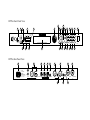
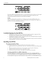
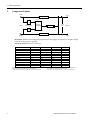
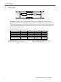
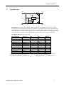
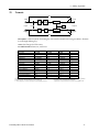
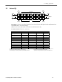
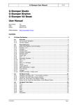
DP/Pro Front Panel View
11
1
2
3
5
48k
Headroom
44.1k
10
6
13 17
18
Effect
Value
32k Sample
Select
Rate
0
14
12
20
21
Edit
Params A
Mod A
Bypass A
Algo B Params B
Mod B
Bypass B
Save
System
Algo A
Find
19
27
Routing
3
Tweak
6
Tap
12
20
Input Level
(Stereo)
L
MIDI In
Meter
Function
30
R
Analog Input
4
Previous
Digital In
professional 24 bit effects processor
Digital Output
7
8
Enter
Next
Compare Cancel
Page
9
MIDI
15 16
22
23
24
25
26
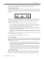
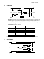
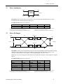
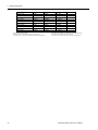
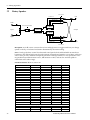
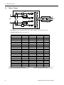
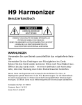
DP/Pro Rear Panel View
29
28
50/60Hz
100 -240VAC
~
WARNING!
To reduce the risk of
fire or electric shock do
not expose this product
to rain or moisture.
30
In
In
31
Out
MIDI Thru
32
33
34
MIDI Out
MIDI In
Foot Sw
1&2
35
37
L
40
41
push
push
R
L
R
+4 dBu
Out
S/PDIF
AES/EBU
Digital Audio
DP/Pro
Outputs
36
-10 dBv
Inputs
I/O Level
38
39
TRS Inputs & Outputs
are Bal/Unbal
Power
Front and Rear Panel Key
1.
2.
3.
4.
5.
6.
7.
8.
9.
10.
11.
12.
13.
14.
15.
16.
17.
18.
19.
20.
21.
Input Level Knob—set analog input level to the DP/Pro.
Headroom LEDs—show analog input level to, or digital
output level from, the DP/Pro
Meter Function switch—sets behavior of Headroom LEDs.
Meter Function LED—shows current meter function.
Sample Rate LEDs—show the DP/Pro current sample rate.
Auxiliary display—shows effect, algo and parameter numbers.
MIDI In LED—lights to show incoming MIDI data.
Digital In LED—lights to show presence of digital sync.
Main DP/Pro display
Value knob—is used to select effects, algos and adjust
parameters.
Tweak button—provides access to Tweak parameters and
virtual Tweak knobs.
Select Effect button—accesses the list of effects currently in
the DP/Pro’s internal memory; repeated presses moves
between effect banks.
Find Effect button—accesses Effect Finder.
Tap button—can be tapped to set the DP/Pro’s system tempo
for synchronized effects.
Previous Page button—scrolls the DP/Pro’s display back
through parameters and moves cursor during some
operations.
Next Page button—scrolls the DP/Pro’s display forward
through successive parameters and moves cursor during some
operations.
Routing button—provides access to signal-flow settings, and
to copy/swap functions.
Algo A and Algo B buttons—intitiates selection of algorithms
and/or algorithm variations for ESP-A and ESP-B.
Params A and Params B buttons—provides access to mixing,
algorithm and Tweak parameter settings for ESP-A and ESP-B.
Mod A and Mod B buttons—provides access to real-time
modulation parameters for ESP-A and ESP-B.
Bypass A and Bypass B buttons—bypasses ESP-A and/or ESP-B.
22.
23.
24.
25.
26.
27.
28.
29.
30.
31.
32.
33.
34.
35.
36.
37.
38.
40.
41.
Enter button—executes various DP/Pro operations.
Compare button—toggles between edited and last-saved
version of currently selected effect.
Cancel button—undoes last operation.
Save button—intitiates process of saving effects to memory.
System/MIDI button—provides access to global parameters.
Power switch—turns the DP/Pro on and off.
AC Line jack—connects power cord to DP/Pro.
S/PDIF Input and Output jacks—connects DP/Pro to an S/PDIF
digital device when a DI-Pro Digital I/O board is installed.
AES/EBU Input and Output jacks—connects DP/Pro to an AES/EBU
digital device when a DI-Pro Digital I/O board is installed.
MIDI In jack—receives MIDI data.
MIDI Out jack—transmits MIDI data from the DP/Pro.
MIDI Thru jack—passes received MIDI data out from the DP/Pro.
Foot SW 1 & 2 jack—connects a dual foot switch to the DP/Pro.
Left XLR Analog Output jack—sends analog audio from the DP/Pro’s
left stereo bus.
Left 1/4” Analog Output jack—sends analog audio from the DP/Pro’s
left stereo bus.
Right XLR Analog Output jack—sends analog audio from the
DP/Pro’s right stereo bus.
Right 1/4” Analog Output jack—sends analog audio from the
DP/Pro’s right stereo bus.
Combination 1/4” and XLR Left Input jack—receives analog audio
to be sent into the DP/Pro’s left stereo bus.
Combination 1/4” and XLR Right Input jack—receives analog audio
to be sent into the DP/Pro’s right stereo bus.
Table of Contents
Reference Manual Table of Contents
1—Introduction .............................................................................. 1
Welcome.................................................................................................................... 1
Parameters, Values and Pages ........................................................................................ 1
Navigating the DP/Pro.................................................................................................. 1
LEDs .............................................................................................................................................................................2
A Note About Read-Only Displays...................................................................................................................2
The DP/Pro Architecture ............................................................................................... 3
Effects...........................................................................................................................................................................3
Effect Finder....................................................................................................................................................4
The DP/Pro’s Two ESP2 Processor Chips......................................................................................................4
The Contents of ESP-A and ESP-B..........................................................................................................5
Fast Editing of Parameters.........................................................................................................................5
Bypassing ESP-A and ESP-B.....................................................................................................................5
Copying and Swapping Algorithms......................................................................................................5
Routing........................................................................................................................................................................6
Real-Time Effect Modulation...............................................................................................................................6
The Virtual Tweak Knobs..........................................................................................................................6
The Mod LFOs ...............................................................................................................................................6
Synchronizing Effects to a Tempo .....................................................................................................................7
The DP/Pro and MIDI...........................................................................................................................................7
Defining your DP/Pro Workspace....................................................................................................................7
Important: Two Final Concepts..........................................................................................................................7
Downloading and Installing.....................................................................................................................7
Saving................................................................................................................................................................8
Available Options for the DP/Pro.................................................................................... 8
Installing the DP/Pro .................................................................................................... 8
Powering Up the First Time.................................................................................................................................8
Powering up the DP/Pro in a MIDI Configuration .........................................................................9
Polarization and Grounding.....................................................................................................................9
AC Line Conditioning.................................................................................................................................9
Rack Mounting Guidelines........................................................................................................................10
Temperature Guidelines.............................................................................................................................10
Setting Analog Input Levels........................................................................................... 10
Troubleshooting .......................................................................................................... 11
Battery Replacement...............................................................................................................................................11
Reinitializing the DP/Pro.....................................................................................................................................11
To Reinitialize the DP/Pro........................................................................................................................11
2—System/MIDI Parameters ........................................................... 13
What Are the Global System and MIDI Parameters?........................................................... 13
The Numbering of the System/MIDI Parameters .......................................................................................13
Selecting the Type of Audio to be Processed..................................................................... 14
Establishing the DP/Pro’s Sample Rate ............................................................................ 14
Global MIDI Settings ................................................................................................... 15
Setting Up a Reference for Time-Based Effects ................................................................. 20
Creating Your Own App Category for Effect Finder........................................................... 22
Grouping Effects for Easy Selection ................................................................................ 23
Designating Real-Time Controllers ................................................................................. 25
Setting Up Foot Switch Controls..................................................................................... 26
Using the Tweak Knobs with MIDI Controllers ................................................................. 28
MIDI Bypassing of the ESPs.......................................................................................... 28
Determining What Happens When You Bypass an ESP....................................................... 29
Enabling/Disabling Status Messages................................................................................ 30
Protecting Effects from Accidental Erasure....................................................................... 31
Setting What Happens When You Turn On the DP/Pro ....................................................... 31
Table of Contents
Automatic Installation of Effects and Algorithms............................................................... 31
Setting Gain-Reduction Metering ................................................................................... 32
Processing a Single Mono Audio Signal........................................................................... 32
Setting the Global Wet/Dry Mix..................................................................................... 33
Personalizing EQ Low Frequency and High Gain Limits..................................................... 33
Showing or Hiding Unused Effect Memory Locations ........................................................ 34
Viewing the DP/Pro’s Operating System Version .............................................................. 35
3—Selecting and Finding Effects ..................................................... 37
Selecting Effects ......................................................................................................... 37
The Effect-Selection Displays..............................................................................................................................37
Selecting Effects from the DP/Pro’s Front Panel.........................................................................................38
Automatic Installation of Effects........................................................................................................................38
Selecting Effects Via MIDI....................................................................................................................................38
Finding Effects ........................................................................................................... 39
Effect Finder..............................................................................................................................................................39
The Effect Finder Criteria.....................................................................................................................................39
The “All” Setting for an Effect Finder Criterion................................................................................39
The Routing Criterion.................................................................................................................................39
The FX Criterion ...........................................................................................................................................39
The App Criterion........................................................................................................................................40
The Effect Finder Display.....................................................................................................................................40
Performing a Find ...................................................................................................................................................40
The Results of a Find...................................................................................................................................41
4—Signal Routing........................................................................... 43
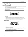
Choosing a Signal Path................................................................................................. 43
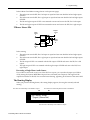
Processing a Single Mono Audio Source .............................................................................................45
The Routing Display ..............................................................................................................................................45
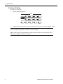
Selecting a Routing .................................................................................................................................................46
5—Selecting Algorithms and Variations........................................... 47
Choosing New Algorithms and Variations........................................................................ 47
The DP/Pro Algorithms .......................................................................................................................................47
Variations...................................................................................................................................................................48
The Special *User Variation* ....................................................................................................................48
The Algorithm-and Variation Selection Displays........................................................................................48
The Selection of Algorithms and Variations..................................................................................................49
6—Editing Algorithms .................................................................... 51
The Algo Params Display ............................................................................................. 51
Editing Algorithm Parameter Settings.............................................................................. 51
A Note About
Mix parameters .............................................................................................................................................52
Shared LFO Waveshapes .............................................................................................. 52
The DP/Pro Algorithm Parameters.................................................................................. 53
No Effect.....................................................................................................................................................................53
Mastering Limiter....................................................................................................................................................53
Compressor/Limiter..............................................................................................................................................54
Compressor ...............................................................................................................................................................55
Servo Limiter.............................................................................................................................................................56
3-Band Comp/Lim .................................................................................................................................................57
Expander ....................................................................................................................................................................58
Stereo Gate.................................................................................................................................................................59
Dual-Mono Gate ......................................................................................................................................................60
De-Esser......................................................................................................................................................................61
Stereo Synthesizer...................................................................................................................................................62
Stereo Re-Imager .....................................................................................................................................................62
Variable-Tap Delay.................................................................................................................................................63
Spatial Delays ...........................................................................................................................................................64
Table of Contents
Ping-Pong Delay ......................................................................................................................................................66
Stereo Delay...............................................................................................................................................................67
Loop Recorder...........................................................................................................................................................68
Expert Reverb............................................................................................................................................................69
Expert Reverb 2 ........................................................................................................................................................70
Reflection Modeler ..................................................................................................................................................72
Small Ambience 1 ....................................................................................................................................................73
Small Ambience 2 ....................................................................................................................................................74
Non-Lin Reverb 1.....................................................................................................................................................75
Non-Lin Reverb 2.....................................................................................................................................................76
Multi-Pitch Shift .......................................................................................................................................................77
Multi-Chorus.............................................................................................................................................................79
Flanger.........................................................................................................................................................................81
Phaser...........................................................................................................................................................................82
Tremolo .......................................................................................................................................................................84
Panner..........................................................................................................................................................................85
Chatter Box.................................................................................................................................................................86
Rotary Speaker..........................................................................................................................................................87
Tunable Speaker.......................................................................................................................................................88
Parametric EQ...........................................................................................................................................................89
Octave EQ...................................................................................................................................................................90
Delay+Chorus...........................................................................................................................................................91
Delay+Flanger...........................................................................................................................................................92
Delay+Phaser ............................................................................................................................................................93
Distortion+Chorus...................................................................................................................................................94
Distortion+Flanger..................................................................................................................................................95
Distortion+Phaser....................................................................................................................................................96
Signal Generator.......................................................................................................................................................97
7—Copying and Swapping Algorithms............................................. 99
Using the Copy/Swap Tools........................................................................................... 99
The Copy/Swap Display ......................................................................................................................................99
Performing a Copy/Swap Procedure...............................................................................................................99
Moving Algorithms Between Effects Using AlgoMover................................................................100
8—Mixing....................................................................................... 101
The ESP-A and ESP-B Mixer Parameters......................................................................... 101
The Mixer Params Display...................................................................................................................................101
Editing Mixer Parameter Settings......................................................................................................................102
Setting an ESP’s Input Level................................................................................................................................102
Setting an ESP’s Stereo Input Balance..............................................................................................................102
Setting the Amount of Signal Fed Back to ESP-A from ESP-B ................................................................103
Setting the Stereo Balance of Signal Fed Back to ESP-A from ESP-B ....................................................103
Setting an ESP’s Output Level ............................................................................................................................104
Setting an ESP’s Wet/Dry Output Balance ....................................................................................................104
9—Tweak Parameters ..................................................................... 107
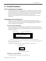
The Tweak Parameter Solution....................................................................................... 107
Designating Tweak Parameters....................................................................................... 107
The Set Tweak Params Display ..........................................................................................................................107
Setting Up a Tweak Parameter ...........................................................................................................................108
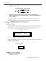
Accessing and Adjusting Tweak Parameters ..................................................................... 108
The Tweak Display..................................................................................................................................................108
Tweaking a Tweak Parameter.............................................................................................................................109
10—Effect Modulation .................................................................... 111
Real-Time Effect Modulation......................................................................................... 111
Overview of Setting Up Real-Time Modulation................................................................. 111
The Modulation Displays......................................................................................................................................112
Selecting a Modulator................................................................................................... 112
Table of Contents
Creating a Modulation Reception Window ....................................................................... 113
Setting Up the Interpretation of Modulator Values ............................................................. 113
Choosing a Parameter to be Modulated............................................................................ 114
Choosing a Modulation Method ..................................................................................... 114
Methods and Shared Destination Parameters....................................................................................114
Setting a Modulation Range........................................................................................... 115
Setting an Additive Modulation Range...........................................................................................................115
Setting an Absolute Modulation Range ..........................................................................................................116
Getting to Know the DP/Pro Modulators.......................................................................... 116
Overview of the DP/Pro’s Virtual Tweak Knobs........................................................................................116
Naming an Effect’s Tweak Knobs .....................................................................................................................116
Activating a Tweak Knob.....................................................................................................................................117
MIDI and the Tweak Knobs .....................................................................................................................117
Overview of the Mod LFOs.................................................................................................................................118
Setting the Mod LFO’s Wave Shape.................................................................................................................118
Setting a Mod LFO’s Speed..................................................................................................................................119
Determining the Phase of Synchronized LFOs.............................................................................................119
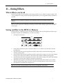
11—Saving Effects .......................................................................... 121
Where Effects are Saved............................................................................................... 121
Saving an Effect to the DP/Pro’s Memory ........................................................................ 121
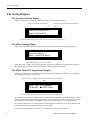
The Saving Displays .................................................................................................... 122
The Location Selection Display ..........................................................................................................................122
The Effect-Naming Display .................................................................................................................................122
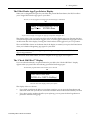
The Effect Finder FX Type Selector Display ..................................................................................................122
The Effect Finder App Type Selector Display...............................................................................................123
The “Check Old Effect?” Display ......................................................................................................................123
The “Replace Old Effect?” Display ...................................................................................................................124
12—Supplemental Information........................................................ 125
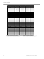
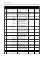
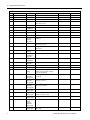
DP/Pro Bank 2 ROM Effects List ................................................................................... 125
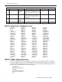
DP/Pro Real-Time Modulators List................................................................................. 130
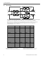
DP/Pro MIDI Implementation........................................................................................ 130
MIDI Implementation Chart ...............................................................................................................................131
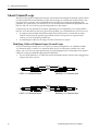
Converting Mono Foot Switches for Use with the DP/Pro ................................................... 132
Replace the Mono Foot Switch Plug with a Stereo Plug ...........................................................................132
Build a Box to Merge Two Mono Foot Switches into One Stereo Jack.................................................133
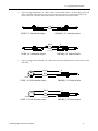
About Ground Loops ................................................................................................... 134
Modifying Cables to Eliminate Input Ground Loops ................................................................................134
Need More Help? ........................................................................................................ 136
13—Glossary .................................................................................. 137
Index....................................................................................... 142
1—Introduction
1—Introduction
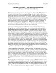
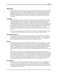
Welcome
Congratulations on your purchase of the ENSONIQ DP/Pro Professional 24-bit Effects Processor. The
DP/Pro Reference Manual provides descriptions of all of the DP/Pro’s many features, and provides
tips for unlocking the product’s tremendous sonic potential.
Tip: Be sure to check out ENSONIQ’s World Wide Web home page at
<http://www.ensoniq.com> from time to time for the latest info on the DP/Pro and other
ENSONIQ products.
Parameters, Values and Pages
There are three basic terms that underlie every DP/Pro activity, and which must be understood. They
are:
•
•
•
Parameter—A parameter is any one of the DP/Pro’s programmable attributes.
Value—A value is a parameter’s setting.
Page—The DP/Pro’s front-panel buttons provide access to a great many parameters, often
presented one after another on sequentially arranged displays. Each display is called a “page.”
Tip: A parameter is described by the button with which it’s associated. For example, if a
parameter is referred as a “System/MIDI parameter,” you’ll know that it’s one of the group of
parameters accessed by pressing the System/MIDI button.
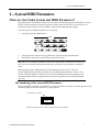
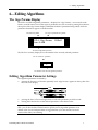
Navigating the DP/Pro
It’s simple to navigate the DP/Pro’s pages and perform its operations once you understand the frontpanel tools central to so many of its activities:
•
The Next and Previous Page buttons allow you to move forward or back, and across, the
DP/Pro’s pages.
Effect
Select
Find
Tweak
Tap
Previous
Next
Page
Tip: The Next and Previous Page buttons, when held down, will scroll through multiple
pages.
ENSONIQ DP/Pro Reference Manual
1
1—Introduction
•
The Value knob, when it’s turned clockwise or counter-clockwise, changes the setting of the
currently selected parameter. It’s also used, in conjunction with the virtual tweak knobs, as a realtime controller (described later in this chapter).
Value
•
The Enter button, when pressed, executes an operation, or functions as a “Yes” answer to a
displayed question. When an Enter button-press is required to complete an operation, its LED
flashes.
Edit
Algo A Params A
Mod A
Bypass A
Algo B Params B
Mod B
Bypass B
Save
System
Routing
Enter
Compare
Cancel
MIDI
•
The Cancel button provides a mechanism for undoing edits and procedures. Its precise behavior
varies somewhat depending on what it is you’re doing and what’s showing on the DP/Pro’s
display. The procedures described throughout the Reference Manual detail the specific role that
the Cancel button plays in each context.
Edit
Algo A Params A
Mod A
Bypass A
Algo B Params B
Mod B
Bypass B
Save
System
Routing
Enter
Compare
Cancel
MIDI
Tip: Many parameters in the DP/Pro can be reset to their nominal values by double-clicking
the Cancel button.
LEDs
The small lightbulbs—LEDs (for "Light Emitting Diode")—in many of the DP/Pro's buttons light to
help you keep track of where you are in the DP/Pro.
A Note About Read-Only Displays
Each of the areas within the DP/Pro has its own set of displays, which are described in detail in the
chapters of the DP/Pro Reference Manual. The DP/Pro provides a number of read-only displays for
informational purposes, in addition to its many adjustable parameters. When a displayed value is
2
ENSONIQ DP/Pro Reference Manual
1—Introduction
read-only, its name will be followed by a colon (“:”). The names of all editable parameters are
followed by an “equals” symbol (“=”).
Tip: See the Glossary in Chapter 13 for definitions of terms used in the DP/Pro Reference
Manual and software.
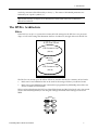
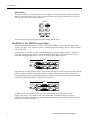
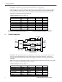
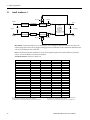
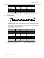
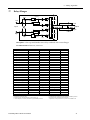
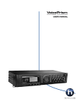
The DP/Pro Architecture
Effects
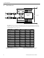
In the DP/Pro, an effect is a preset that contains all of the settings for the DP/Pro’s two processor
chips, as well as the settings that determine the flow of audio into, through and out of the DP/Pro.
A DP/Pro Effect
ESP Processor Chip
(ESP-A)
Routing
Setting
ESP Processor Chip
(ESP-B)
The DP/Pro can contain up to 387 effects. Effects are stored in the DP/Pro’s memory in four banks:
•
•
Banks 0 and 1 are RAM banks that can be used for the storage of effects you edit and create.
Banks 2 and 3 are ROM banks that contain effects programmed by ENSONIQ; these effects are
always available and uneraseable.
Effects can be selected using the DP/Pro’s Select Effect button and the Value knob, with a foot switch
(such as the ENSONIQ SW-10) or with Program Changes and Bank Select messages received via
MIDI.
Effect
Select
Find
Tweak
Tap
Previous
Next
Page
ENSONIQ DP/Pro Reference Manual
3
1—Introduction
Effect Finder
The DP/Pro offers a powerful mechanism for locating the desired effect from the many available in
memory. This mechanism—Effect Finder—searches for effects according to criteria that you provide.
Effect Finder is accessed via the Find button.
Effect
Select
Find
Tweak
Tap
Previous
Next
Page
To learn more about selecting effects and Effect Finder, see Chapter 3.
The DP/Pro’s Two ESP2 Processor Chips
The basic building blocks of DP/Pro effects are two of ENSONIQ’s second-generation 24-bit ESP2
custom VLSI chips. “ESP” is an acronym for “ENSONIQ Signal Processing.” The two chips are called
ESP-A and ESP-B.
Each ESP uses an algorithm—a highly specialized digital signal processing program—to perform an
audio processing task. The DP/Pro contains 42 different algorithms, any of which can be used by
either ESP. Each algorithm offers its own set of useful presets, called variations.
Edit
Algo A Params A
Mod A
Bypass A
Algo B Params B
Mod B
Bypass B
Routing
Algorithm and variation selection occurs after pressing the Algo A (for ESP-A) and Algo B (for ESP-B)
buttons. Chapter 5 explains in detail the manner in which algorithms and variations are selected.
Each algorithm contains a comprehensive suite of parameters, accessed via the Params A and Params
B button. Algorithms parameters are described in Chapter 6.
Edit
Algo A Params A
Mod A
Bypass A
Algo B Params B
Mod B
Bypass B
Routing
In addition, each ESP contains its own set of mix-related parameters that govern the ESP’s
input/output levels, stereo balances and, where applicable, its feedback settings. The mixer
parameters are also found under the Params A and Params B buttons. The ESP-A and ESP-B Mixer
Params are described in Chapter 8.
4
ENSONIQ DP/Pro Reference Manual
1—Introduction
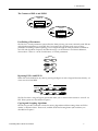
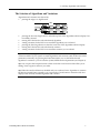
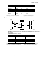
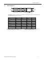
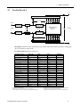
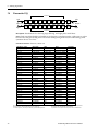
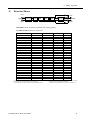
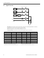
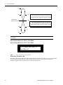
The Contents of ESP-A and ESP-B
input
controls
ESP-A
ALGORITHM
output
controls
the algorithm's
parameters
ESP-B
input
controls
ALGORITHM
output
controls
the algorithm's
parameters
Fast Editing of Parameters
The DP/Pro’s Tweak parameters system offers the ability to bring your most-commonly used ESP mix
and algorithm parameters up to the DP/Pro’s front panel. This provides quick access to these
parameters for editing without requiring you to navigate through all of the parameters available for
each ESP and algorithm. Chapter 9 describes the setup—via the Params A and Params B buttons,
shown above—and use—via the Tweak button—of Tweak parameters.
Effect
Select
Find
Tweak
Tap
Previous
Next
Page
Bypassing ESP-A and ESP-B
Either ESP can be disabled at any time by pressing the Bypass A and/or Bypass B buttons directly, via
a foot switch or from MIDI.
Edit
Algo A Params A
Mod A
Bypass A
Algo B Params B
Mod B
Bypass B
Routing
The DP/Pro offers a range of bypass options that allow you to control what it means to “turn off” an
ESP. These options are described in Chapter 2.
Copying and Swapping Algorithms
The DP/Pro provides a selection of tools for moving algorithms and their settings from one ESP to
another, or between effects. These tools, available under the Routing button (shown below), are
described in Chapter 7.
ENSONIQ DP/Pro Reference Manual
5
1—Introduction
Routing
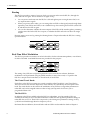
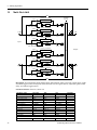
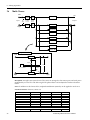
The DP/Pro provides a variety of ways in which you can pass audio into the DP/Pro, through the
ESPs, and back out again. This is referred to as signal routing.
•
You can process audio sent into the DP/Pro’s left and right inputs as a single stereo feed, or as
two separate mono signals.
•
When you process stereo audio, you can arrange the two ESPs so that signal passes through them
separately, from ESP-A into ESP-B, or in a feedback loop, where audio goes into ESP-A, then ESPB ,and then back to ESP-A again.
•
You can also determine whether the stereo outputs of the ESPs will be mixed together, presenting
a single stereo feed at the DP/Pro’s outputs, or whether the ESPs will each use their own single
output.
Routing options are access by pressing the Routing button. Chapter 4 describes the DP/Pro’s routing
options in detail.
Edit
Algo A Params A
Mod A
Bypass A
Algo B Params B
Mod B
Bypass B
Routing
Real-Time Effect Modulation
The DP/Pro provides an extensive set of tools that allow for the real-time manipulation, or modulation,
of effects. The Mod A and Mod B buttons are provided for this purpose.
Edit
Algo A Params A
Mod A
Bypass A
Algo B Params B
Mod B
Bypass B
Routing
The setting of any ESP mix or algorithm parameter can be controlled in real-time. Real-time
modulation can be performed using any MIDI controller, a stereo foot switch, a CV pedal or the
DP/Pro’s unique virtual controllers, its Tweak knobs, or mod LFOs.
The Virtual Tweak Knobs
Each effect in the DP/Pro contains two virtual controllers called Tweak Knob 1 and Tweak Knob 2.
These two devices are software objects that, when enabled, are controlled by the front-panel Value
knob. The tweak knobs can be used for the modulation of any ESP mix or algorithm parameters in
either ESP, and can be assigned names in order to help you keep track of what it is you’ve
programmed them to do.
The Mod LFOs
In addition to the LFOs available within the DP/Pro’s algorithms, two free-standing LFOs are
available at all times for use as real-time modulators of ESP mix and algorithm parameter settings in
either ESP: the mod LFOs. These LFOs can provide cyclical changes to parameters’ settings, as they
cycle back and forth through their low-frequency waves.
Real-time effect modulation, the tweak knobs and mod LFOs are described in detail in Chapter 9.
6
ENSONIQ DP/Pro Reference Manual
1—Introduction
Synchronizing Effects to a Tempo
Many of the DP/Pro’s algorithms contain elements that can be synchronized to a timing reference. The
DP/Pro contains a system clock to provide such a pulse. The system clock can be set to be internally
controlled or to respond to received MIDI clocks. When the system clock is not linked to an external
MIDI timing source, its rate may be set manually, or by tapping the desired tempo on the front-panel
Tap button. The Tap button—whose LED flashes the current system tempo—is itself highly
configurable. Chapter 2 provides information on the system clock and setting up the Tap button.
Effect
Select
Find
Tweak
Tap
Previous
Next
Page
The DP/Pro and MIDI
The DP/Pro is a MIDI-conversant device, allowing the selection of effects, bypassing and real-time
modulation via MIDI. The DP/Pro’s basic MIDI characteristics are provided in its System/MIDI
parameters, described in Chapter 2.
Edit
Algo A Params A
Mod A
Bypass A
Algo B Params B
Mod B
Bypass B
Save
System
Routing
Enter
Compare
Cancel
MIDI
Defining your DP/Pro Workspace
The DP/Pro’s overall operation is quite customizable. The System/MIDI button —shown
above—provides access to the many parameters that allow you to make your DP/Pro working
environment comfortable. The System/MIDI parameters are described in Chapter 2.
Important: Two Final Concepts
Downloading and Installing
In the DP/Pro, the selection of an effect, algorithm or algorithm variation does not necessarily mean
that it’s ready for use:
•
When an effect is selected, the DP/Pro must be instructed to download all of the effect’s
algorithm settings into its ESPs, and to configure the effect’s signal routing.
•
When an algorithm or algorithm variation is selected, the DP/Pro must be instructed to
download all of the algorithm’s settings into the selected ESP.
The DP/Pro allows you to choose whether you’d like it to download, or install, these objects as they’re
selected, or whether you’d like the option of installing effects and/or algorithms (and variations)
manually by pressing the Enter button after you’ve selected them. If you choose the latter, the Enter
button will flash after you’ve selected an effect, algorithm or algorithm variation to remind you that it
needs to be pressed.
ENSONIQ DP/Pro Reference Manual
7
1—Introduction
Edit
Algo A Params A
Mod A
Bypass A
Algo B Params B
Mod B
Bypass B
Save
System
Routing
Enter
Compare
Cancel
MIDI
The System/MIDI AutoLoad parameter allows you to determine the DP/Pro’s behavior in this regard.
When the DP/Pro is shipped from the factory, algorithms and algorithm variations are set to
automatically download, while effects are set for manual installation.
Saving
When you’re editing effects in the DP/Pro—including every non-System/MIDI parameter—the
changes you make are not permanent until you save the effect you’re working on. See Chapter 11 to
learn how to save effects to the DP/Pro’s memory.
Edit
Algo A Params A
Mod A
Bypass A
Algo B Params B
Mod B
Bypass B
Save
System
Routing
Enter
Compare
Cancel
MIDI
Available Options for the DP/Pro
•
•
•
ENSONIQ SW-10 Dual Foot Switch—provides left and right foot pedals in a single unit. These
foot pedals can be configured to perform many tasks in the DP/Pro.
ENSONIQ DI-Pro Digital I/O Board—provides AES-EBU and S/PDIF digital inputs and outputs
for the DP/Pro. The DI-Pro is user-installable.
ADC-24—upgrades the DP/Pro’s analog-to-digital and digital-to-analog converters from 20-bit to
24-bit performance. The ADC-24 is user-installable.
Installing the DP/Pro
Powering Up the First Time
The correct procedure for powering up the DP/Pro for the first time is as follows:
1. Make sure the DP/Pro’s power button is turned off—the bottom of the button should be pressed
in.
2. Plug the provided line cord into the AC line receptacle on the rear panel of the DP/Pro.
3. Plug the other end of the line cord into a grounded AC outlet.
4. Press the top of the Power button on the right side of the DP/Pro’s front panel.
Powering up the DP/Pro in a MIDI Configuration
In a series of MIDI devices, you should always turn on the device that’s transmitting MIDI data
(keyboards, sequencers, etc.) before you power up the device that’s receiving MIDI data. For instance,
if you’re using the DP/Pro to receive MIDI information from a keyboard or sequencer, you should
turn the keyboard or sequencer on before the DP/Pro. This prevents any unwanted MIDI information
8
ENSONIQ DP/Pro Reference Manual
1—Introduction
from being “spit” out of the transmitting device during power up, which could confuse or disable
your DP/Pro. If this should happen, turn off the DP/Pro, and then turn it back on.
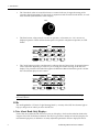
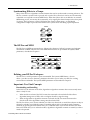
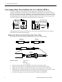
Polarization and Grounding
Like many modern electrical devices, the DP/Pro has a three-prong power cord with earth ground to
ensure safe operation. Some products have power cords with only two prongs and no earth ground.
For safety, some of these products have polarized plugs which can only be inserted into an outlet the
proper way.
Non-polarized
Polarized
Three-prong
with earth ground
Some products, such as older guitar amplifiers, do not have polarized plugs and can be connected to
an outlet incorrectly. This may result in dangerous high voltages on the audio connections, which
could cause you physical harm, or damage any properly grounded equipment to which they are
connected, such as your DP/Pro.
To avoid shock hazards or equipment damage, we recommend the following precautions:
•
If you own equipment with two-pronged power cords, check to see if they’re polarized or nonpolarized. You might consider having an authorized repair station change any non-polarized
plugs on your equipment to polarized plugs to avoid future problems.
•
Exercise caution when using extension cords or plug adapters. Proper polarization should always
be maintained from the outlet to the plug. The use of polarized extension cords and adapters is
the easiest way to maintain proper polarity.
•
Whenever possible, connect all products with grounded power cords to the same outlet ground.
This will ensure a common ground level to prevent equipment damage and minimize hum in the
audio output.
AC outlet testers are available from many electronic supply and hardware stores. These can be used to
check for proper polarity of outlets and cords.
For more information on grounding the DP/Pro, see Chapter 12.
AC Line Conditioning
As with any computer device, the DP/Pro is sensitive to sharp peaks and drops in the AC line voltage.
Lightning strikes, power drops, or sudden and erratic surges in the AC line voltage can scramble the
internal memory, and in some cases, damage the unit’s hardware. Here are a few suggestions to help
guard against such occurrences:
•
•
A surge/spike suppressor—this absorbs surges and protects your gear from all but the most
severe over-voltage conditions. You can get multi-outlet power strips with built-in surge/spike
suppressors for little more than the cost of unprotected power strips, so purchasing one is a good
investment for all your electronic equipment.
A line conditioner—this is the best, but by far the more expensive way to protect your gear. In
addition to protecting against surges and spikes, a line conditioner guards equipment against
excessively high or low line voltages. If you use the DP/Pro in lots of different locations with
varying or unknown AC line conditions, you might consider investing in a line conditioner.
Rack Mounting Guidelines
Because the DP/Pro uses an internal transformer, it generates a certain amount of heat. For better
reliability, we don’t recommend the installation of the DP/Pro near devices that are particularly
sensitive to heat, or near power amps, tube equipment, or other products that emit a lot of heat.
ENSONIQ DP/Pro Reference Manual
9
1—Introduction
Temperature Guidelines
The DP/Pro contains computerized and electronic circuitry that can be susceptible to damage when
exposed to extreme temperature changes. When the DP/Pro is brought inside after sitting in a cold
climate (i.e., the back seat of your car), condensation builds up on the internal circuitry in much the
same way a pair of glasses fogs up when you come inside on a cold day. If the unit is powered up as
this condensation occurs, components can short out or be damaged. Excessively high temperatures
also pose a threat to the unit, stressing both the internal circuits as well as the case. With this in mind,
we advise you to follow these precautions when storing, mounting and setting up your DP/Pro:
•
•
•
Avoid leaving the DP/Pro in temperatures of less than 50 degrees Fahrenheit or more than 100
degrees Fahrenheit.
When bringing the DP/Pro indoors after travel, allow at least 20 minutes for the unit to reach
room temperature before powering up. In the case of extreme outdoor temperatures (below 50
degrees Fahrenheit or above 100 degrees Fahrenheit), allow an hour or more before powering up.
Avoid leaving the DP/Pro inside a vehicle exposed to direct sunlight.
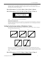
Setting Analog Input Levels
The DP/Pro can accept +4dB or -10dB input levels. The rear panel I/O level switch should be set to
match the output of your sending device.
+4 dBu
-10 dBv
I/O Level
The DP/Pro’s Headroom LEDs show the level of incoming analog audio whenever the Meter Function
switch is in the out, or up, position. The LEDs under the Meter Function switch show the current state
of the Headroom LEDs.
Headroom
0
3
6
12
20
Meter
Function
30
L
R
Analog Input
Digital Output
The optimal input level for the DP/Pro is just below the point at which the red Headroom LEDs light.
Since the DP/Pro provides its best signal-to-noise performance when its Input Level knob is set
straight up, it’s a good idea to set the knob to this position and then adjust the output levels of your
sending device to obtain a healthy Headroom LED reading.
Input Level
(Stereo)
Troubleshooting
Battery Replacement
The DP/Pro “remembers” its effects and various settings even when its power is turned off, since it
contains a battery which keeps its memory intact. All batteries eventually become discharged, and
10
ENSONIQ DP/Pro Reference Manual
1—Introduction
though your DP/Pro battery should last for years, you may eventually need to have it replaced by an
authorized ENSONIQ Repair Station.
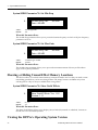
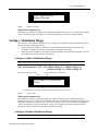
The DP/Pro will tell you when its battery needs replacing. It will flash the following when you power
up:
Warning! Main battery is
low. See manual.
This display will appear only briefly, and then allow you to proceed normally. Make sure that
everything in RAM that you’d like to keep—or any special system settings—have been safely stored
on an external MIDI storage device—as described in Chapter 2—and take the DP/Pro to an
authorized ENSONIQ Repair Station as soon as possible to have the battery replaced.
Reinitializing the DP/Pro
All computer-based devices—including the DP/Pro—occasionally experience signs of data
corruption. If your DP/Pro begins acting oddly, you can reinitialize its software to clear out any
problems lurking there.
Warning: Make sure you’ve saved any effects or system settings that you want to preserve to
an external MIDI device before reinitializing. Reinitializing erases the contents of the
DP/Pro’s user memory banks, and resets all System/MIDI parameters to their default values.
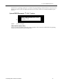
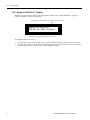
To Reinitialize the DP/Pro
1.
2.
3.
Hold down the System/MIDI button.
While continuing to hold the System/MIDI button, press the Cancel button.
Let go of both buttons. The displays shows:
Press ENTER to Reinit. All data
will be lost!
4.
Press the Enter button to reinitialize the DP/Pro.
ENSONIQ DP/Pro Reference Manual
11
2—System/MIDI Parameters
2—System/MIDI Parameters
What Are the Global System and MIDI Parameters?
The global System and MIDI parameters provide options for determining the overall behavior of your
DP/Pro. These parameters create the framework within which all other DP/Pro operations occur.
Certain special procedures are also available via the System/MIDI parameter pages.
All of the System and MIDI parameters are accessed by:
•
pressing the System/MIDI button.
Edit
Algo A Params A
Mod A
Bypass A
Algo B Params B
Mod B
Bypass B
Save
System
Routing
Enter
Compare
Cancel
MIDI
•
•
pressing the Next and Previous Page buttons to navigate among the parameters.
turning the Value knob to set the selected parameter’s value.
Tip: When you’ve altered a parameter’s value, you can press the Cancel button to undo your
edit. You can also double-click the Cancel button to quickly set any parameter to its default
value.
Tip: Important System/MIDI parameters are bookmarked for easy access. Press the
System/MIDI button repeatedly to jump from one bookmarked parameter to the next. You
can also use this technique to quickly access any System/MIDI parameter by jumping to the
nearest bookmark and then using the Next or Previous Page buttons to locate the parameter
you want.
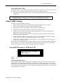
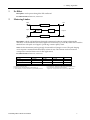
The Numbering of the System/MIDI Parameters
The System/MIDI parameters are numbered—as each parameter is selected, its number appears in the
auxiliary display to the left of the DP/Pro’s main display.
“P” stands for “parameter”
m
P 27
i
This shows the number of the currently displayed and selected parameter
ENSONIQ DP/Pro Reference Manual
1
2—System/MIDI Parameters
Selecting the Type of Audio to be Processed
The first step in using the DP/Pro is determining the type of audio you’ll be sending into its input
jacks. All DP/Pros can process analog audio. Any DP/Pro with an ENSONIQ DI-Pro digital I/O
board installed can also process incoming digital audio in AES and S/PDIF formats.
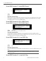
System/MIDI Parameter 1: Input
k
Values:
Default:
Input=Analog Clock=48.000
kHz
Analog; Digital, AES; Digital, S/PDIF; Ana+Dig, AES; Ana+Dig, S/PDIF
Analog
Note: The listed values are available when the optional DI-Pro digital I/O board is installed in
the DP/Pro. When the DI-Pro board is not present, only the Analog setting is visible.
What this Parameter Does:
The Input parameter selects the type of audio source you’ll be sending into the DP/Pro. Rear-panel
combination 1/4”/XLR jacks are provided for analog signals, and the optional DI-Pro digital I/O
board provides digital inputs for AES- and S/PDIF-format data.
Establishing the DP/Pro’s Sample Rate
The DP/Pro’s A/D and D/A converters can operate at several different sample rates.
When an analog signal is being processed, the DP/Pro can operate at either 44.100 kHz or 48.000 kHz.
Both rates have their advantages and disadvantages. The 48.000 kHz provides the highest-quality
signal processing. However, should you be using the DP/Pro’s digital outputs to master an analog
signal to CD or some other digital medium that operates at 44.100 kHz, you’ll need to use the same
sample rate in the DP/Pro.
Note: The DP/Pro’s Sample Rate LEDs—located above the auxiliary display—show the
DP/Pro’s current sample rate.
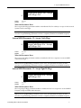
System/MIDI Parameter 2: Clock
k
Values:
Default:
2
Input=Analog Clock=48.000
kHz
44.100 kHz (when Input=Analog); 48.000 kHz (when Input=Analog)
48.000 kHz
ENSONIQ DP/Pro Reference Manual
2—System/MIDI Parameters
What this Parameter Does:
The Clock parameter sets or displays the sample rate used by the DP/Pro’s A/D and D/A converters.
The behavior of this parameter is dependent on the setting of the Input parameter.
•
When Input=Analog, the setting of the Clock parameter determines the operating sample rate of
the DP/Pro.
System/MIDI parameters 3 through 5 are available only when a DI-Pro digital I/O board has been
installed in the DP/Pro. See the DI-Pro User’s Guide for information on these parameters.
Global MIDI Settings
The DP/Pro is a highly MIDI-aware device:
•
•
•
•
•
DP/Pro effects can be selected via MIDI Program Change and Bank Select messages.
Effects can be modulated in real time using any MIDI controller.
Many aspects of DP/Pro algorithms can be synchronized to MIDI clocks.
The DP/Pro generates and responds to System Exclusive data dumps.
The DP/Pro can transmit control change messages generated by its virtual Tweak knobs, its
Bypass buttons and its dual foot switch.
•
The DP/Pro can transmit Program Change messages when effects are selected from the front
panel, or by using a foot switch.
•
Various elements of MIDI transmission and reception can be individually enabled or disabled;
the DP/Pro also provides an overall MIDI reception on/off parameter.
•
The DP/Pro’s response to Program Change messages can be re-mapped to allow any Program
Change value to select any effect.
The DP/Pro uses three MIDI channels. Program Changes received on the System MIDI channel select
effects, while ESP-A and ESP-B each have their own MIDI channels upon which they receive MIDI
controller messages used for the real-time manipulation of their algorithms.
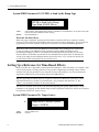
System/MIDI Parameter 6: MIDI Device ID
k
Values:
Default:
MIDI Device ID=0
MIDI Channel=1
System
0 through 127
0
What this Parameter Does:
System Exclusive data is always stamped with a MIDI Device ID number. This is used to identify an
individual device in MIDI setups that contain more than one of a particular product. If you are using
multiple DP/Pros, make sure that each has been assigned its own Device ID number if you intend to
be working with System Exclusive data. This includes external MIDI storage devices, as well as remote
editing software on a computer.
ENSONIQ DP/Pro Reference Manual
3
2—System/MIDI Parameters
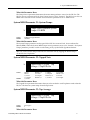
System/MIDI Parameter 7: System MIDI Channel
k
Values:
Default:
MIDI Device ID=0
MIDI Channel=1
System
1 through 16
1
What this Parameter Does:
MIDI Program Change and Bank Select messages received on the System MIDI channel select effects
(see Chapter 3 to learn more about selecting effects via MIDI). This parameter allows you to set the
System MIDI channel to any of the 16 MIDI channels.
System/MIDI Parameter 8: ESP-A MIDI Channel
System/MIDI Parameter 9: ESP-B MIDI Channel
ESP-A MIDI Channel=2
MIDI Channel=3
Values:
Defaults:
ESP-B
1 through 16
ESP-A MIDI Channel: 2; ESP-B MIDI Channel: 3
What this Parameter Does:
Any parameter in any DP/Pro algorithm can be manipulated in real time via MIDI controller
messages. ESP-A and ESP-B each have their own MIDI channel upon which they receive such MIDI
data. Either may be set to respond to any MIDI channel.
System/MIDI Parameter 10: Accept MIDI Msgs
k
Values:
Default:
Accept MIDI Msgs=Yes Accept
SysEx Msgs=Yes
No; Yes
Yes
What this Parameter Does:
The Accept MIDI Msgs parameter enables or disables the DP/Pro’s response to MIDI messages of any
kind.
Note: When this parameter is set to “No,” the settings of System/MIDI parameters 11 through
13 will have no effect.
System/MIDI Parameter 11: Accept SysEx Msgs
4
ENSONIQ DP/Pro Reference Manual
2—System/MIDI Parameters
k
Values:
Default:
Accept MIDI Msgs=Yes Accept
SysEx Msgs=Yes
No; Yes
Yes
What this Parameter Does:
The Accept SysEx Msgs parameter enables or disables the DP/Pro’s ability to accept or load received
System Exclusive messages.
Note: If the Accept MIDI Msgs parameter is set to “Off,” this parameter will have no effect,
since the Accept MIDI Msgs parameter will have completely disabled overall MIDI reception.
System/MIDI Parameter 12: Accept Cntlr Msgs
k
Values:
Default:
Accept Cntlr Msgs=Yes Accept
PrgCh Msgs=Yes
No; Yes
Yes
What this Parameter Does:
The Accept Cntlr Msgs parameter enables or disables the DP/Pro’s response to received MIDI
controller messages.
Note: If the Accept MIDI Msgs parameter is set to “Off,” this parameter will have no effect,
since the Accept MIDI Msgs parameter will have completely disabled overall MIDI reception.
System/MIDI Parameter 13: Accept PgmCh Msgs
k
Values:
Default:
Accept Cntlr Msgs=Yes Accept
PrgCh Msgs=Yes
No; Yes
Yes
What this Parameter Does:
The Accept PrgCh Msgs parameter enables or disables the DP/Pro’s response to received MIDI
Program Change and Bank Select messages.
Note: If the Accept MIDI Msgs parameter is set to “Off,” this parameter will have no effect,
since the Accept MIDI Msgs parameter will have completely disabled overall MIDI reception.
ENSONIQ DP/Pro Reference Manual
5
2—System/MIDI Parameters
System/MIDI Parameter 14: Transmit Cntlr Msgs
k
Values:
Default:
Transmit Cntlr Msgs=No
Transmit PrgCh Msgs=No
No; Yes
No
What this Parameter Does:
The Transmit Cntlr Msgs parameter enables or disables the DP/Pro’s transmission of MIDI controller
data from either of its virtual Tweak knobs, bypass button or dual foot switch.
System/MIDI Parameter 15: Transmit PrgCh Msgs
k
Values:
Default:
Transmit Cntlr Msgs=No
Transmit PrgCh Msgs=No
No; Yes
No
What this Parameter Does:
The DP/Pro can transmit a corresponding Program Change and Bank Select message each time you
select an effect from the DP/Pro’s front panel. The Transmit PrgCh Msgs parameter enables or
disables this feature.
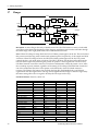
System/MIDI Parameter 16:MIDI Pgm Chngs
k
Values:
Default:
MIDI Pgm Changes=Direct
Map=000 > Effect=None
Direct; Use Map
Direct
What this Parameter Does:
The MIDI Pgm Chngs parameter determines the manner in which the DP/Pro will respond to
received Bank Select and Program Change messages. When the parameter is set to:
•
“Direct,” each received Bank Select and Program Change message will select the like-numbered
bank and effect.
•
“Use Map,” you can designate the effects to be selected by particular Program Change values.
This parameter functions in conjunction with System/MIDI parameters 17 and 18, described below.
System/MIDI Parameter 17: Map
6
ENSONIQ DP/Pro Reference Manual
2—System/MIDI Parameters
MIDI Pgm Changes=Direct
Map=000 > Effect=None
i
Values:
Default:
000 to 127
000
What this Parameter Does:
The Map parameter operates in conjunction with System/MIDI parameters 16 and 18. It selects a
Program Change value to be linked to the effect selected with parameter 18 whenever parameter 16 is
set to “Use Map.”
System/MIDI Parameter 18: (Map) Effect
MIDI Pgm Changes=Direct
Map=000 > Effect=None
i
Values:
Default:
None; 0000* through 3005
None
What this Parameter Does:
The Effect parameter operates in conjunction with System/MIDI parameters 16 and 17, described
above. Set the Effect parameter to the number of the effect you’d like selected when the DP/Pro
receives the Program Change value displayed in the Map field to its left. This feature is active only
when parameter 16 is set to “Use Map.”
Each effect is shown as a four-digit number. The first digit represents the bank in which the effect is
stored. The three remaining digits show the program number of each effect within the selected bank.
If System/MIDI parameter 76 is set to “Yes,” an asterisk following the effect’s bank and program
numbers shows that the memory location is currently empty. ” If parameter 76 is set to “No,” unused
locations will not be available for selection by this parameter.
ENSONIQ DP/Pro Reference Manual
7
2—System/MIDI Parameters
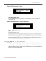
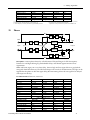
System/MIDI Parameter 19: ENTER to Send SysEx Dump Type
ENTER to Send SysEx Dump
Type=Bank 0 RAM Effects
Values:
Default:
Selected Effect; Bank 0 RAM Effects; Bank 1 RAM Effects; All RAM Effects; All System Params (this
includes all System/MIDI parameter settings)
Bank 0 RAM Effects
What this Parameter Does:
When this page is displayed, pressing the Enter button causes the DP/Pro to transmit a System
Exclusive (SysEx) data dump of the object selected on the lower line of the display. This provides an
opportunity to store the contents of the DP/Pro’s memory in an external MIDI storage device.
Note: Since SysEx data records the MIDI Device ID number of the sending device, make sure
to note the setting of the MIDI Device ID parameter (System/MIDI parameter 6) when
performing the dump. In order to successfully reload the data back into the DP/Pro at a later
date, this Device ID number must match the one embedded in the SysEx data. In addition, the
Accept SysEx Msgs System/MIDI parameter (12) must be set to “Yes” in order for the DP/Pro
to reload SysEx data transmitted from an external source.
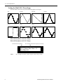
Setting Up a Reference for Time-Based Effects
Many of the DP/Pro’s algorithms contain time-based elements—LFOs and delays, for example—that
can be synchronized to a timing reference. This provides a high degree of timing control of those
elements. The DP/Pro provides its own internal clock for such purposes, or it can synchronize its
algorithms to MIDI clocks received from and external MIDI device.
Tip: The algorithm parameter charts in Chapter 6 of the DP/Pro Reference Guide show which
algorithm elements are capable of synchronization. Any parameter with the letter “T” (for
“Time”) in its Attributes column can be synchronized.
The DP/Pro’s internal clock can be set by manually adjusting the System/MIDI System Tempo
parameter, or by tapping out the desired tempo on the Tap button. The DP/Pro can be set to respond
to Tap button strikes in a variety of ways.
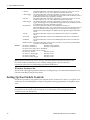
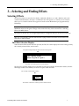
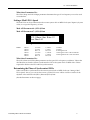
System/MIDI Parameter 20: Tempo Source
k
Values:
Default:
8
Tempo Source=Internal System
Tempo=120 BPM
Internal; MIDI Clock
Internal
ENSONIQ DP/Pro Reference Manual
2—System/MIDI Parameters
What this Parameter Does:
The Tempo Source parameter determines the master timing reference source for the DP/Pro. The
DP/Pro uses its own internal clock when Tempo Source is set to “Internal.” The DP/Pro can also use
MIDI clocks received from an external source when this parameter is set to “MIDI Clock.”
System/MIDI Parameter 21: System Tempo
k
Values:
Default:
Tempo Source=Internal System
Tempo=120 BPM
40 BPM through 400 BPM
120 BPM
What this Parameter Does:
The System Tempo parameter sets the speed of the DP/Pro’s internal clock, shown in Beats Per
Minute (BPM). When the System/MIDI Tempo Source parameter (16) is set to “Internal,” the System
Tempo parameter provides control over the timing of any synchronized algorithm elements.
Tip: You can also set the tempo of the DP/Pro’s internal clock by tapping the desired tempo
on the DP/Pro’s Tap button.
System/MIDI Parameter 22: Tapped Note
k
Values:
Default:
Tapped Note=1/4 Note Tap
Average=2 TapLED=On
4 Beats
3 Beats
1/2 Note
1/2 Triplet
1/4 Note
Dotted 1/4
1/4 Note
1/4 Triplet
Dotted 1/8
1/8 Note
1/8 Triplet
Dotted 1/16
1/16 Note
1/16 Triplet
Dotted 1/32
1/32 Note
1/32 Triplet
What this Parameter Does:
The Tapped Note parameter determines the note value ascribed to each Tap button strike when the
DP/Pro calculates its system tempo from the Tap button.
System/MIDI Parameter 23: Tap Average
Tapped Note=1/4 Note Tap
Average=2 TapLED=On
i
Values:
Default:
2 through 8
2
What this Parameter Does:
ENSONIQ DP/Pro Reference Manual
9
2—System/MIDI Parameters
The Tap Average parameter determines the number of Tap button strikes the DP/Pro will average in
order to calculate the timing of the system tempo. You can also set the note value of each tap—see
System/MIDI parameter 20, Tapped Note.
System/MIDI Parameter 24: TapLED
Tapped Note=1/4 Note Tap
Average=2 TapLED=On
i
Values:
Default:
Off; On
On
What this Parameter Does:
The TapLED parameter turns on or off the LED in the DP/Pro’s Tap button. The Tap LED flashes at
the current system tempo when this parameter is set to “On.”
Creating Your Own App Category for Effect Finder
The DP/Pro’s Effect Finder can search for effects according to the manner in which they’re used.
These possible uses are presented as the various App—for “Application”—categories in Effect Finder
(for more on using Effect Finder, see Chapter 3). You can also create up to 10 of your own usage
categories for situations not covered by those already written into the DP/Pro’s software. Each can
contain up to 10 effects This will allow you to use Effect Finder to locate effects according to your
unique needs.
Each of the 10 user-defined categories can be selected from among the App values in Effect
Finder—they’re listed as Groups 1 to 10.
System/MIDI Parameter 25: Finder App Group
k
Values:
Default:
Finder App Group =1
Effect=None
Item=1 >
1 through 10
1
What this Parameter Does:
The Finder App Group parameter selects one of the 10 App groups. Once you’ve selected a group, you
can choose the effects you want to assign to the group by assigning an effect to each item number.
10
ENSONIQ DP/Pro Reference Manual
2—System/MIDI Parameters
System/MIDI Parameter 26: Item
Finder App Group =1
Effect=None
Item=1 >
i
Values:
Default:
1 through 10
1
What this Parameter Does:
The Item parameter selects one of the 10 items—you can think of this as a slot—available in the
selected App group.
System/MIDI Parameter 27: (App Group) Effect
Finder App Group =1
Effect=None
Item=1 >
i
Values:
Default:
None; 0000* through 3005
None
What this Parameter Does:
The Effect parameter allows you to assign one of the DP/Pro’s effects to the currently selected item.
Each effect is shown as a four-digit number. The first digit represents the bank in which the effect is
stored. The three remaining digits show the program number of each effect within the selected bank.
If System/MIDI parameter 76 is set to “Yes,” an asterisk following the effect’s bank and program
numbers shows that the memory location is currently empty. ” If parameter 76 is set to “No,” unused
locations will not be available for selection by this parameter.
Grouping Effects for Easy Selection
The DP/Pro allows you to group effects together as songs—a DP/Pro song is a list of effects meant to
be selected one after the other. A song can use any of the effects in the DP/Pro, arranged in any order.
There can be up to 10 steps in each song—each step being associated with a single effect—and up to 10
songs in the DP/Pro’s memory at any given time. You can move forward or back through the list by
pressing the pedals on a dual foot switch—such as an ENSONIQ SW-10 (see the System/MIDI L Ftsw
Cntlr and R Ftsw Cntlr parameters below).
ENSONIQ DP/Pro Reference Manual
11
2—System/MIDI Parameters
System/MIDI Parameter 28: Song
m
Song=1 Name=Undefined Step=1
> Effect=None
Values:
Default:
1 through 10
1
What this Parameter Does:
The Song parameter selects one of the 10 DP/Pro songs. Once you’ve selected a song, you can name
the song, and then assign an effect to each of its steps.
System/MIDI Parameters 29-39: Name
m
Song=1 Name=Undefined Step=1
> Effect=None
Values:
Default:
Symbols, numbers, upper- and lower-case characters
“Undefined”
What these Parameters Do:
The System/MIDI song page’s Name fields allow you to name the song you’re constructing. Use the
Next and Previous Page buttons to underline each character in turn—when a character is underlined,
it can be edited. Turn the Value knob to select the desired character.
System/MIDI Parameter 40: Step
Song=1 Name=Undefined Step=1
> Effect=None
i
Values:
Default:
1 through 10
1
What this Parameter Does:
The Step parameter selects one of the 10 steps available in the selected song.
12
ENSONIQ DP/Pro Reference Manual
2—System/MIDI Parameters
System/MIDI Parameter 41: (Song) Effect
Song=1 Name=Undefined Step=1
> Effect=None
i
Values:
Default:
None; 0000* through 3005
None
What this Parameter Does:
The Effect parameter allows you to assign any of the DP/Pro’s effects to the step currently selected
with the Step parameter.
Each effect is shown as a four-digit number. The first digit represents the bank in which the effect is
stored. The three remaining digits show the program number of each effect within the selected bank.
If System/MIDI parameter 76 is set to “Yes,” an asterisk following the effect’s bank and program
numbers shows that the memory location is currently empty. ” If parameter 76 is set to “No,” unused
locations will not be available for selection by this parameter.
Designating Real-Time Controllers
Every parameter in each of the DP/Pro’s algorithms can be manipulated in real time, allowing for the
creation of highly animated effect processing. The DP/Pro supports the use of a wide variety of
control mechanisms, ranging from the two virtual Tweak knobs, to foot switches, to all 121 MIDI
controllers.
The first step in setting up real-time control of the DP/Pro’s effects is to establish of suite of up to 16
control mechanisms that you’d like to have available for this purpose—these are referred to as DP
Cntlrs 1 through 16. You can use any of the 16 for real-time control of any algorithm parameter.
To learn more about real-time control of the DP/Pro’s effects, see Chapter 10.
System/MIDI Parameters 42 through 57: DP Cntlr 1 through DP Cntlr 16
DP Cntlr 1 =TwkKnob 1 DP
Cntlr 2 =TwkKnob 2
Values:
Off
TwkKnob1
TwkKnob2
LFO 1
LFO 2
ENSONIQ DP/Pro Reference Manual
This setting disables the selected DP Cntlr.
The selected DP Cntlr will use the first of the DP/Pro’s two virtual tweak knobs.
To utilize Tweak Knob 1 from the DP/Pro’s front panel, the Tweak LED must be
lit and the Knob 1 Name parameter must be showing when these conditions are
met, the Value knob operates as the displayed tweak knob. Tweak Knob 1 may be
used as a real time controller via MIDI at any time, regardless of the state of the
Tweak LED or the DP/Pro’s display (see “Using the Tweak Knobs with MIDI
Controllers” later in this chapter).
This serves a similar function as the “Twk Knob 1” setting, except that it enables
the use of the second of the DP/Pro’s two virtual tweak knobs; see above.
The selected DP Cntlr will use the first of two mod LFOs available in each DP/Pro
effect.
The selected DP Cntlr will use the second of two mod LFOs available in each
DP/Pro effect.
13
2—System/MIDI Parameters
L FootSw
Defaults:
The selected DP Cntlr will use the left pedal of a dual foot switch as an on/off
modulator that’s in its “on” state whenever the pedal is depressed.
L FtSwToggle
The selected DP Cntlr will use the left pedal of a dual foot switch as an on/off
toggle; alternating presses of the pedal will apply either a full modulation value or
no modulation to the target algorithm parameter.
R FootSw
The selected DP Cntlr will use the right pedal of a dual foot switch as an on/off
modulator that’s in its “on” state whenever the pedal is depressed.
R FtSwToggle
The selected DP Cntlr will use the right pedal of a dual foot switch as an on/off
toggle; alternating presses of the pedal will apply either a full modulation value or
no modulation to the target algorithm parameter.
NoteNumber
The selected DP Cntlr will use received MIDI note numbers to
generatemodulation values. Lower note numbers (such as those played by the low
notes on a MIDI keyboard) will generate lower modulation values; higher note
numbers (notes played higher on a MIDI keyboard) generate higher modulation
values.
Velocity
The selected DP Cntlr will use received MIDI velocity values as modulation
values.
Aftertouch
The selected DP Cntlr will use received MIDI aftertouch values as modulation
values.
PitchBend
The selected DP Cntlr will use received MIDI pitch bend values as modulation
values.
MIDI controllers The selected DP Cntlr will use received values for any of the 121 possible MIDI
controllers as modulation values.
DP Cntlr 1=TwkKnob 1
DP Cntlr 9=Note Number
DP Cntlr 2=TwkKnob 2
DP Cntlr 10=ModWheel#1
DP Cntlr 3=LFO 1DP Cntlr 11=PitchBend
DP Cntlr 4=LFO 2DP Cntlr 12=Velocity
DP Cntlr 5=L FootSw
DP Cntlr 13=Off
DP Cntlr 6=L FtSwToggle
DP Cntlr 14=Off
DP Cntlr 7=R FootSw
DP Cntlr 15=Off
DP Cntlr 8=R FtSwToggle
DP Cntlr 16=Off
Note: The DP Cntlrs may be re-set to use any control mechanism. The default values for the
first 12 DP Cntlrs are intended to serve as handy starting points—they are also used
extensively in the DP/Pro’s ENSONIQ-programmed ROM effects.
What these Parameters Do:
The DP Cntlr 1 through 16 parameters allow you to designate up to 16 control mechanisms for use as
real-time controllers of the DP/Pros effects.
Setting Up Foot Switch Controls
The DP/Pro provides a rear-panel Foot Sw 1&2 jack for the connection of a stereo—two-pedal—foot
switch such as an ENSONIQ SW-10. Either of the pedals can be programmed to accomplish various
tasks.
Note: The DP/Pro is designed for use with a dual foot switch, though modified mono
footswitches can be used as well. See Chapter 12 for information on converting mono foot
switches for use with the DP/Pro.
14
ENSONIQ DP/Pro Reference Manual
2—System/MIDI Parameters
System/MIDI Parameter 58: L Ftsw Cntlr
System/MIDI Parameter 59: R Ftsw Cntlr
L Ftsw Cntlr=DP Cntlr
Cntlr=DP Cntlr
Values:
Off
DP Cntlr
Tap Tempo
Inc Effect
Dec Effect
Inc Song
Dec Song
Inc Step
Dec Step
Bypass A
Bypass B
Defaults:
R Ftsw
The foot switch will be inactive.
The foot switch may be selected as a DP Cntlr and designated to perform real-time
modulation on the DP/Pro’s effects. DP Cntlrs 5-8 default to using the left and
right foot switches.
The foot switch operates in the same manner as the front-panel Tap tempo button.
(See the Tap Average, Tap LED and Tapped notes System/MIDI parameters
earlier in this chapter.)
Each press of the foot switch selects the next effect in the DP/Pro’s memory.
Each press of the foot switch selects the next lowest effect in the DP/Pro’s
memory.
Each press of the foot switch selects the next song in the DP/Pro’s memory.
Each press of the foot switch selects the next lowest song in the DP/Pro’s
memory.
Each press of the foot switch selects the next step in the currently selected song
Each press of the foot switch selects the next lowest step in the currently selected
song.
Each press of the foot switch toggles the bypass state of ESP-A. The nature of the
bypass is determined by the ESP-A Bypass Btn parameter described later in this
chapter.
Each press of the foot switch toggles the bypass state of ESP-B. The nature of the
bypass is determined by the ESP-B Bypass Btn parameter described later in this
chapter.
DP Cntlr
What these Parameters Do:
The L Ftsw Cntlr and R Ftsw Cntlr parameters assign tasks to the two foot switches on a dual foot
switch.
MIDI Transmission from the Foot Switches
Whenever the System/MIDI Transmit Cntlr Msgs parameter (14) is on, pressing a foot switch pedal
transmits MIDI data. The kind of data transmitted depends on the current job to which the pedal is
assigned:
•
•
•
When the foot switch is being used for the selection of effects, a Program Change value
equivalent to each selected effect is transmitted. This occurs when foot switch is set to Inc Effect,
Dec Effect, Inc Step or Dec Step.
When the foot switch is set to Bypass A or Bypass B , it mimics the pressing of the appropriate
Bypass button. As a result, the DP/Pro will transmit an On (127) or Off (0) value for the controller
currently selected for turning the ESP’s bypass on and off via MIDI (see “Bypassing ESPs with
MIDI” later in this chapter).
When a foot switch is set to DP Cntlr, Tap Tempo, Inc Song or Dec Song and pressed, the DP/Pro
transmits a value of 127 for MIDI controllers 70 (the left pedal) or 71 (the right pedal). When the
pedal is released, a 0 value for the same controller is transmitted. These controllers are
understood as left and right Patch Select button-presses by ENSONIQ products that have Patch
Select buttons.
ENSONIQ DP/Pro Reference Manual
15
2—System/MIDI Parameters
Using the Tweak Knobs with MIDI Controllers
Setting up:Tweak knobs:MIDI transmissionThe DP/Pro Tweak Knob 1 and 2 transmit and respond to
MIDI controllers. This allows you to record real-time tweaks into a MIDI sequencer, which can
reproduce the tweaks on playback by transmitting the data back to the DP/Pro. Both Tweak Knob 1
and 2 can be set to transmit and respond to any MIDI controller.
Tip: To learn more about the DP/Pro Tweak knobs, see Chapter 10.
System/MIDI Parameter 60: Twk 1 Cntlr
System/MIDI Parameter 61: Twk 2 Cntlr
Twk 1 Cntlr=FXCtrl1 #12
2 Cntlr=FXCtrl2 #13
Values:
Defaults:
Twk
Off; All MIDI controllers
Twk 1 Cntlr: FXCtrl1 #12; Twk 2 Cntlr: FXCtrl2 #13
What these Parameters Do:
The Twk 1 Cntlr and Twk 2 Cntlr parameters allow you to assign any MIDI controller to be
transmitted from the DP/Pro when the Tweak LED is lit and the Tweak Knob1 or Tweak Knob2 pages
are displayed. The Tweak knobs will also respond to this controller at all times—even when the
Tweak LED is off—as long as the System/MIDI Accept MIDI Msgs parameter is set to “Yes.”
Note: The Tweak knobs send and receive MIDI data on the System MIDI channel (see the
description of the System MIDI Channel parameter earlier in this chapter).
MIDI Bypassing of the ESPs
The DP/Pro allows you to bypass its ESPs by sending MIDI controllers of your choice on the
DP/Pro’s system MIDI channel. This feature acts in the same manner as pressing the Bypass A and/or
Bypass B buttons on the DP/Pro’s front panel. When the DP/Pro receives a value of 64 or above for a
selected controller, it switches on the target ESP’s bypass function. Values of 64 or below turn the
bypass off.
When the System/MIDI Transmit Cntlr Msgs parameter is set to “On,” pressing the front panel
Bypass buttons transmits either a 127 (when bypass is switched on) or 0 (when bypass is switched off)
value for the selected controller from the DP/Pro’s MIDI Out jack.
Note: The nature of the bypass is determined by the setting of the System/MIDI ESP-A Bypass
Btn and ESP-B Bypass Btn parameters, described later in this chapter.
System/MIDI Parameter 62: Byp A Cntlr
System/MIDI Parameter 63: Byp B Cntlr
16
ENSONIQ DP/Pro Reference Manual
2—System/MIDI Parameters
Byp A Cntlr=Off
Cntlr=Off
Values:
Defaults:
Byp B
Off; All MIDI controllers
Off
What these Parameters Do:
The Byp A Cntlr and Byp B Cntlr parameters allow you to designate a MIDI controller for each ESP
that can be used to toggle the ESP’s bypass function on or off. An On (127) or Off (0) value for the
MIDI controller will also be transmitted from the DP/Pro each time one of the Bypass buttons is
pressed.
Determining What Happens When You Bypass an ESP
The DP/Pro provides a Bypass button for each ESP as a way to quickly disable it. You can also use a
dual foot switch or a MIDI controller to switch the Bypass buttons on and off (see “Setting Up Foot
Switch Controls” earlier in this chapter, and “MIDI Bypassing of the ESPs” above).
The DP/Pro allows you to determine exactly what will occur when an ESP is bypassed. There are
several possibilities, useful for different situations.
System/MIDI Parameter 64: AlgoA Bypass Btn
System/MIDI Parameter 65: AlgoB Bypass Btn
ESP-A BypassBtn=Bypass ESP-B
BypassBtn=Bypass
Values:
Default:
Bypass—shuts off the audio processing being applied by the ESP, allowing dry audio to continue to
pass through.
Inp Mute—stops the inputting of audio into the ESP, allowing any signal already being processed to
finish sounding in a natural manner
Out Mute—stops the output of the ESP, instantly cutting off all audio. This setting allows you to
continue sending audio into the ESP, so that when you deactivate the bypass, any audio currently
being processed will be heard.
All Mute—stops both the input to and the output from the ESP.
Bypass
What this Parameter Does:
The ESP-A Bypass Btn and ESP-B Bypass Btn parameters let you control precisely the behavior of the
ESPs when they’re bypassed.
Tip: Double-clicking either Bypass button sets the selected ESP to All Mute, regardless of the
setting of ESP-A Bypass Btn or ESP-B Bypass Btn parameters.
Enabling/Disabling Status Messages
You can set the DP/Pro so that it will display messages informing you:
•
of the current bypass state of the ESP whose Bypass button you’ve just pressed.
ENSONIQ DP/Pro Reference Manual
17
2—System/MIDI Parameters
•
that the DP/Pro is installing either the last-saved version of the currently selected effect or the
contents of the edit buffer when you press the Compare button.
System/MIDI Parameter 66: Display Bypass State
k
Values:
Default:
Display Bypass State=Off Show
Compare Message=Off
Off; On
Off
What this Parameter Does:
The Display Bypass State parameter determines whether the DP/Pro will display a status message
each time a Bypass button is pressed (On) or not (Off).
System/MIDI Parameter 67: Show Compare Message
k
Values:
Default:
Display Bypass State=Off Show
Compare Message=Off
Off; On
Off
What this Parameter Does:
The Show Compare Message parameter determines whether the DP/Pro will display a message
telling you when it’s installing the last-saved version of the currently selected effect or the contents of
the edit buffer, to help you keep track of which version of an effect is in place.
18
ENSONIQ DP/Pro Reference Manual
2—System/MIDI Parameters
Protecting Effects from Accidental Erasure
The DP/Pro provides a memory-protection feature to help prevent the accidental erasure of effects in
banks 0 and 1 as you create, edit, save, and perhaps inadvertently overwrite, effects.
System/MIDI Parameter 68: Memory Protect
k
Values:
Default:
Memory Protect=Off System
Wake Up=Restart
Off; On
Off
What this Parameter Does:
The Memory Protect parameter enables (On) or disables (Off) the safeguarding of effects in the
DP/Pro’s user banks from accidental erasure.
Setting What Happens When You Tu rn On the DP/Pro
The System/MIDI Wake Up parameter can be set so that the DP/Pro powers up in either of two
states:
•
•
Restart—The DP/Pro will power up with the default factory effect, DepTh oF SpaCe, selected.
Restore—The DP/Pro will restart with the last-selected effect still selected.
System/MIDI Parameter 69: System Wake Up
k
Values:
Default:
Memory Protect=Off System
Wake Up=Restart
Restart; Restore
Restart
What this Parameter Does:
The System/MIDI Wake Up parameter allows you to determine whether or not the DP/Pro will retain
its effect selection at power-down when you turn it back on.
Automatic Installation of Effects and Algorithms
Automatic installation of effects, algorithms and variations:enabling and disablingWhenever an effect
or algorithm is selected, it must be installed before it can be used. The DP/Pro can:
•
•
automatically perform this task a moment after each effect, algorithm or algorithm variation is
selected.
wait until you press the Enter button to execute the installation—when this is the case, the Enter
button’s LED will flash to remind you that the selected effect, algorithm or algorithm variation
has not yet been installed.
System/MIDI Parameter 70: AutoLoad
ENSONIQ DP/Pro Reference Manual
19
2—System/MIDI Parameters
k
Values:
Default:
AutoLoad=Algos
Range=18 dB
Meter
Off—Effects and algorithms must be installed after selection by pressing the Enter button.
Algos—Algorithms and algorithm variations will be automatically installed upon selection.
Effects—Effects will be automatically installed upon selection.
Algos & Effects—Effect, algorithms and algorithm variations will be automatically installed upon
selection.
Algos
What this Parameter Does:
The AutoLoad parameter determines whether or not effects and/or algorithms and their variations
will be automatically installed by the DP/Pro upon selection.
Tip: You may find it easier to shop for effect, algorithms and variations with this parameter
turned off, so that the DP/Pro will not perform an installation each time you pause during the
selection process.
Setting Gain-Reduction Metering
The DP/Pro’s algorithms that pertain to dynamics, such as its compressors and limiters, incorporate
gain-reduction. The displays that show the current amount of gain reduction can be scaled to depict
various dB ranges, providing a coarser or finer view of gain reduction.
System/MIDI Parameter 71: Meter Range
k
Values:
Default:
AutoLoad=Algos
Range=18 dB
Meter
3 dB through 48 dB, in 3dB steps
18 dB
What this Parameter Does:
The Meter Range parameter determines the scale of gain-reduction displays presented in the DP/Pro’s
dynamics-related algorithms.
Processing a Single Mono Audio Signal
The DP/Pro’s routing structures anticipate that you’ll be sending audio into both of the DP/Pro’s left
and right inputs, whether that audio is a single stereo image or two separate mono feeds. However, if
you’d prefer to use only a single input, the DP/Pro allows you to select the one you’d like to use,
switching the unused input off.
System/MIDI Parameter 72: Mono Input Src
20
ENSONIQ DP/Pro Reference Manual
2—System/MIDI Parameters
k
Values:
Default:
Mono Input Src=Off Global Wet
Mix=100% Wet
Off; L-Input; R-Input
Off
What this Parameter Does:
The Mono Input Src parameter allows you to route only the audio present at either the left or right
input into the DP/Pro’s ESPs.
Setting the Global Wet/Dry Mix
Many of the DP/Pro’s algorithms contain a wet/dry mix parameter to provide control of the
interaction between dry signal and the audio processing provided by the algorithm. In addition, each
ESP offers an additional wet/dry mix—located among its Mixer Params—to help achieve a balance
between the result of the ESP’s processing and the original uneffected signal. Finally, the DP/Pro
allows you set an overall global balance between the original dry signal received at the DP/Pro’s
inputs and the mix produced by the outputs of its ESPs.
System/MIDI Parameter 73: Global Wet Mix
k
Values:
Default:
Mono Input Src=Off Global Wet
Mix=100% Wet
Full Dry through 100% Wet
100% Wet
What this Parameter Does:
The Global Wet Mix parameter allows you to set a balance between the dry signal present at the
DP/Pro’s inputs and the audio produced at the outputs of its two ESPs.
Personalizing EQ Low Frequency and High Gain Limits
The DP/Pro allows you to establish low-frequency and maximum boost limits when editing
algorithms that contain EQ (equalization). Given the DP/Pro’s wide dynamic range, judicious
settings for this parameter can help prevent damage to your ears and/or equipment.
The algorithm parameter charts in Chapter 6 show which parameters are affected by these limits. If a
parameter has an “L” in its Attributes column, it’s affected by the Set Min Freq parameter. If it has a
“G,” it’s affected by the Set Max Gain parameter.
ENSONIQ DP/Pro Reference Manual
21
2—System/MIDI Parameters
System/MIDI Parameter 74: Set Min Freq
k
Values:
Default:
Set Min Freq=1Hz
Gain=+48.0dB
Set Max
1Hz through 20Hz
1Hz
What this Parameter Does:
The Set Min Freq parameter allows you to pre-set the bottom frequency to which an EQ low-frequency
parameter can be set.
System/MIDI Parameter 75: Set Max Gain
k
Values:
Default:
Set Min Freq=1Hz
Gain=+48.0dB
Set Max
+0.0dB through +48.0dB
+48.0dB
What this Parameter Does:
The Set Max Gain parameter allows you to pre-set the maximum amount of boost you’ll be able to
apply to an EQ boost parameter.
Showing or Hiding Unused Effect Memory Locations
The DP/Pro allows you to hide unused memory locations in Banks 0 and 1 so that you needn’t waste
time dialing past them as you browse through effects. The empty locations are hidden only when
selecting effects—they’re always available when saving effects.
System/MIDI Parameter 76: Show Undef Effects
k
Values:
Default:
Show Undef Effects=Yes O.S.
Version: 1.11
No; Yes
Yes
What this Parameter Does:
The Show Undef Effects allows you to display (Yes) or hide (No) unused, or undefined, locations in
the DP/Pro’s two user memory banks.
Viewing the DP/Pro’s Operating System Version
22
ENSONIQ DP/Pro Reference Manual
2—System/MIDI Parameters
The DP/Pro’s operating system (O. S.) contains the programming code that allows it to function. The
DP/Pro provides a read-only display that shows the version of the O.S. currently installed in your
DP/Pro.
System/MIDI Parameter 77: O.S. Version
k
Values:
Show Undef Effects=Yes O.S.
Version: 1.10
Read-only display
What this Parameter Does:
The O.S. Version parameter shows the version number of the currently installed DP/Pro operating
system, the software that controls the DP/Pro.
ENSONIQ DP/Pro Reference Manual
23
3—Selecting and Finding Effects
3—Selecting and Finding Effects
Selecting Effects
The DP/Pro effects are stored in four banks, numbered as Banks 0, 1, 2 and 3. Banks 0 and 1 each
contain 128 RAM memory locations—numbered from 0 through 127—in which you can store the
effects you’ve created or edited. The upper two banks contain ROM effects pre-programmed by
ENSONIQ.
Note: The effect bank and memory locations are numbered as they are to correspond to the
MIDI Bank Select and Program Change values with which they can be selected. See “Selecting
Effects Via MIDI” below.
The effects in the DP/Pro are arranged sequentially in a single list that you can browse at any time.
Tip: You can repeatedly press the Select button to jump from the first effect in each bank to the
first effect in the next bank.
The Effect-Selection Displays
When the Select Effect button has been pressed, the DP/Pro’s main display shows the routing used by
the currently selected effect, and its name.
The signal routing used by the effect is shown on the top line
m
Type=Stereo: Serial
Name=DepTh oF SpaCe
i
The name of the effect appears on the bottom line
The DP/Pro’s auxiliary display shows the bank in which the currently selected effect resides, and the
three-digit number of its memory location it occupies within the bank.
The currently selected bank’s number
m
2000
i
The number of the effect’s memory location within the bank
ENSONIQ DP/Pro Reference Manual
1
3—Selecting and Finding Effects
Selecting Effects from the DP/Pro’s Front Panel
Effects are selected from the DP/Pro’s front panel by:
•
pressing the Select Effect button.
Effect
Select
Find
Tweak
Tap
Previous
Next
Page
•
•
turning the Value knob to browse through the effects in memory to locate the desired effect.
pressing the Enter button to install the effect.
The Enter LED will flash when you’ve selected an effect to remind you that you haven’t yet
installed it. This provides an easy way to tell whether the effect that’s displayed is the effect
you’re hearing.
Tip: If you’ve selected an effect, but not yet installed it, you can press the Cancel button to
return the DP/Pro’s display to the currently installed effect.
Automatic Installation of Effects
The DP/Pro can be set so that it automatically installs effects as they’re selected. See “Automatic
Installation of Effects and Algorithms” in Chapter 2.
Selecting Effects Via MIDI
When the DP/Pro’s System/MIDI Accept MIDI Messages parameter is set to “Yes,” its effects can be
selected via MIDI by:
•
•
sending Bank Select and Program Change messages to the DP/Pro on its system MIDI channel
(see Chapter 2) corresponding to the bank and memory location in which the desired effect
resides.
pressing the Enter button to install the effect.
The Enter button’s LED will flash to remind you to install the effect.
Note: The DP/Pro will ignore MIDI Bank selects and Program Changes that select empty
memory locations.
2
ENSONIQ DP/Pro Reference Manual
3—Selecting and Finding Effects
Finding Effects
Effect Finder
Effect Finder™ can locate effects that meet specified criteria. There are three types of criteria:
•
•
•
Routing—Effect Finder can search for effects that use the specified type of signal routing.
FX—Effect Finder can search for effects that employ a specified type of algorithm.
App—Effect Finder can search for effects that are designated as being used for a specified type of
application.
You can perform an Effect Finder Find procedure utilizing one, two or three of these criteria
simultaneously. Obviously, you can search with a high degree of specificity by using all three criteria
in a single search.
The DP/Pro “knows” the routing of each of its effects, and automatically assigns the appropriate
Routing value to each effect. An effect’s FX and App values are manually assigned when the effect is
saved to memory (see Chapter 11). You can assign as many FX or App values to each effect as you
wish. As you assign these values, you can conform to the below-listed meanings for the different
values to the degree you see fit.
The Effect Finder Criteria
The “All” Setting for an Effect Finder Criterion
Each of the three Effect Finder criteria offers an “All” setting that instructs Effect Finder to accept any
effect that matches any of the criterion’s possible values—the net result of this setting is to turn off the
criterion as a factor in a search. Therefore, whenever a criterion is not a factor in a search, set it to
“All.”
The Routing Criterion
The possible Effect finder choices for the Routing criterion are:
•
•
•
•
•
•
•
All—Use this value if the relationship between the DP/Pro’s ESPs is irrelevant.
S: Serial—will limit the search to effects that employ the Stereo: Serial routing.
S: Feedback—will limit the search to effects that employ the Stereo: Feedback routing.
S: Parallel-S—will limit the search to effects that employ the Stereo: Parallel-S routing.
S: Parallel-M—will limit the search to effects that employ the Stereo: Parallel-M routing.
M: Dual Mono—will limit the search to effects that employ the 2-Mono: Dual Mono routing.
M: Stereo Mix—will limit the search to effects that employ the 2-Mono: Stereo Mix routing.
Note: To learn more about the DP/Pro routings, see Chapter 4.
The FX Criterion
The possible Effect finder choices for the FX criterion are:
•
•
•
•
•
•
•
•
All—Use this value if the algorithm used by the effect you seek are irrelevant to your search.
Reverb—will limit the search to effects using any type of reverb algorithm.
Room—will limit the search to effects using room simulation algorithms.
Hall—will limit the search to effects using concert hall simulation algorithms.
Plate—will limit the search to effects using plate reverb simulation algorithms.
Non-Lin—will limit the search to effects using non-linear reverb algorithms.
Delay—will limit the search to digital delay algorithms.
PitchMod—will limit the search to pitch-modulation algorithms, such as pitch shifters, choruses,
flanger and phasers.
ENSONIQ DP/Pro Reference Manual
3
3—Selecting and Finding Effects
•
•
•
•
•
Spatial—will limit the search to algorithms that create or alter stereo imaging.
Dynamics—will limit the search to algorithms that perform amplitude shaping, such as
compressors, limiters, expanders and gates.
EQ/Filtr—will limit the search to equalization and frequency filtering algorithms.
Amp/Spkr—will limit the search to algorithms that simulate amplifiers, speaker enclosures and
rotary speakers.
Utility—will limit the search to algorithms used for special purposes, such as tone generation.
The App Criterion
The possible Effect finder choices for the App criterion are:
•
•
•
•
•
•
•
•
•
•
•
All—Use this value if the way the effect you seek is usually used is irrelevant to the search.
*Demo—will limit the search to effects designed to show off the capabilities of the DP/Pro.
Live PA
•
Guitar-E
Master
•
Keyboard
Rec/Mix
•
Percussn
Bass
•
Piano
Brass
•
Strings
Drums
•
WindReed
Guitar-A
•
Vocal
*Custom—provides a general catch-all category for effects that don’t quite belong anywhere else.
Group 1-10—The DP/Pro also provides 10 user-definable App types. See Chapter 2 to learn how
to assign effects to one of these groups.
The Effect Finder Display
Each criterion is allotted a portion of the Effect Finder display.
Routing=All
App=All
FX=All
When a criterion is selected for editing, it flashes.
Performing a Find
Effects are found using Effect Finder when you:
•
press the Find Effect button.
Effect
Select
Find
Tweak
Tap
Previous
Next
Page
•
•
4
use the Next and Previous Page buttons to select each criterion in turn.
turn the Value knob to set each criterion as you wish.
ENSONIQ DP/Pro Reference Manual
3—Selecting and Finding Effects
•
press the Find Effect button again to execute the search.
The Find Effect button’s LED will flash to remind you to execute the search.
The Results of a Find
One of two things can occur when you attempt to find effects using Effect Finder: either you’ll find an
effect—or effects—that match your criteria, or you won’t.
If Effect Finder locates any effects, the lowest-numbered effect will be displayed. You can turn the
Value knob to browse through the found effects. Once you’ve found the effect you seek, you can
install it by press the Enter button.
The list of found effects will be available until you:
•
press the Select Effect button, at which point the entire list of the DP/Pro’s effects will be
presented.
•
press the Find Effect button, which will initiate a new Find process.
If Effect Finder finds no effects matching your criteria, the display will show:
No Match Found
You can perform as many Find procedures as you wish. Consider adjusting your criteria, or
broadening the search by setting one or more of the criteria to “All.”
ENSONIQ DP/Pro Reference Manual
5
4—Signal Routing
4—Signal Routing
Choosing a Signal Path
The audio signals sent into the DP/Pro’s left and right inputs can be directed through the DP/Pro and
out of its left and right outputs in a variety of ways. Each of these signal paths—which is called a
routing—provides a different type of effect processing.
Tip: When you select effects n the DP/Pro, each effect’s routing is shown on the top line of the
effect-selection display.
Stereo: Serial
Input
Jacks
L
Output
Jacks
L
ESP-A
ESP-B
Output
Jacks
R
Input
Jacks
R
In this routing:
•
•
•
•
The audio sent into the DP/Pro’s left and right inputs is treated as a single stereo image.
The stereo image is sent into ESP-A.
The left and right outputs of ESP-A are fed into the left and right inputs, respectively, of ESP-B.
The left and right outputs of ESP-B are sent to the DP/Pro’s left and right outputs.
Stereo: Feedback
Input
Jacks
L
Output
Jacks
L
ESP-A
Input
Jacks
R
ESP-B
Output
Jacks
R
In this routing:
•
•
•
•
The audio sent into the DP/Pro’s left and right inputs is treated as a single stereo image.
The stereo image is sent into ESP-A.
The left and right outputs of ESP-A are fed into the left and right inputs, respectively, of ESP-B.
The left and right outputs of ESP-B are sent back to the left and right inputs, respectively, of ESPA, as well as to the DP/Pro’s left and right outputs.
Tip: The amount of signal fed back into ESP-A from ESP-B is controlled by the B>A Input
Level Mixer parameter (see Chapter 8).
ENSONIQ DP/Pro Reference Manual
1
4—Signal Routing
Stereo: Parallel-S
Input
Jacks
L
Output
Jacks
L
ESP-A
Input
Jacks
R
ESP-B
Output
Jacks
R
In this routing:
•
•
•
•
•
The audio sent into the DP/Pro’s left and right inputs is treated as a single stereo image.
One copy of the stereo image is sent into ESP-A.
Another copy of the stereo image is sent into ESP-B.
The left output of ESP-A is summed with the left output of ESP-B and sent to the DP/Pro’s left
output.
The right output of ESP-A is summed with the right output of ESP-B and sent to the DP/Pro’s
right output.
Stereo: Parallel-M
Input
Jacks
L
ESP-A
Input
Jacks
R
ESP-B
Output
Jacks
L
Output
Jacks
R
In this routing:
•
•
•
•
•
The audio sent into the DP/Pro’s left and right inputs is treated as a single stereo image.
One copy of the stereo image is sent into ESP-A.
Another copy of the stereo image is sent into ESP-B.
The left and right outputs of ESP-A are summed to mono and sent to the DP/Pro’s left output.
The left and right outputs of ESP-B are summed to mono and sent to the DP/Pro’s right output.
2-Mono: Dual Mono
Input
Jacks
L
ESP-A
Output
Jacks
L
ESP-B
Input
Jacks
R
2
Output
Jacks
R
ENSONIQ DP/Pro Reference Manual
4—Signal Routing
In the 2-Mono: Dual Mono routing (shown on the previous page):
•
•
•
•
The audio sent into the DP/Pro’s left input is copied and sent into both the left and right inputs
of ESP-A.
The audio sent into the DP/Pro’s right input is copied and sent into both the left and right inputs
of ESP-B.
The left and right outputs of ESP-A are summed to mono and sent to the DP/Pro’s left output.
The left and right outputs of ESP-B are summed to mono and sent to the DP/Pro’s right output.
2-Mono: Stereo Mix
Output
Jacks
L
Input
Jacks
L
ESP-A
Output
Jacks
R
ESP-B
Input
Jacks
R
In this routing:
•
•
•
•
The audio sent into the DP/Pro’s left input is copied and sent into both the left and right inputs
of ESP-A.
The audio sent into the DP/Pro’s right input is copied and sent into both the left and right inputs
of ESP-B.
The left output of ESP-A is summed with the left output of ESP-B and sent to the DP/Pro’s left
output.
The right output of ESP-A is summed with the right output of ESP-B and sent to the DP/Pro’s
right output.
Processing a Single Mono Audio Source
If you’d like to send audio to only one of the DP/Pro’s inputs, you can select the input you’d like to
use by setting the System/MIDI Mono Input Source as desired (see Chapter 2). The signal will be
copied to both sides of the DP/Pro’s internal stereo bussing, appearing in the center of the stereo field.
The Routing Display
When you press the Routing button, the routing display appears, showing the currently selected
routing:
The shows the relationship of the DP/Pro’s inputs
m
This shows the relationship between ESP-A and ESP-B
m
Type=Stereo: Serial
(Input) (StereoOut)
i
This shows the relationship of the DP/Pro’s outputs
ENSONIQ DP/Pro Reference Manual
3
4—Signal Routing
Selecting a Routing
Routings are selected by:
•
pressing the Routing button.
Edit
Algo A Params A
Mod A
Bypass A
Algo B Params B
Mod B
Bypass B
Save
System
Routing
Enter
Compare
Cancel
MIDI
•
turning the Value knob to browse through the effects in memory to select the desired routing.
Note: Not all algorithms work with all of the routings. For this reason, as you change an
effect’s routing, the algorithms available for use may change.
Tip: You can press the Compare button to listen to the last-saved version of the effect you’re
editing. Press it again to return to your edits.
4
ENSONIQ DP/Pro Reference Manual
5—Selecting Algorithms and Variations
5—Selecting Algorithms and Variations
Choosing New Algorithms and Variations
The DP/Pro Algorithms
The DP/Pro’s audio processing is accomplished using software programs called algorithms—or algos.
The two ESP2 chips each employ a single algorithm at a time, as shown in this illustration:
ESP-A
and its mix settings
An algorithm
("algo")
and its parameters
Routing
Setting
ESP-B
and its mix settings
An algorithm
("algo")
and its parameters
Either ESP can use any algorithm from the following list:
1.
2.
3.
4.
5.
6.
7.
8.
9.
10.
11.
12.
13.
14.
15.
No Effect
Mastering Limiter
Compressor/Limiter
Compressor
Servo Limiter
3-Band Comp/Lim
Expander
Stereo Gate
Dual-Mono Gate
De-Esser
Stereo Synthesizer
Stereo Re-Imager
Variable-Tap Delay
Spatial Delays
Ping-Pong Delay
16.
17.
18.
19.
20.
21.
22.
23.
24.
25.
26.
27.
28.
29.
30.
Stereo Delay
Loop Recorder
Expert Reverb
Expert Reverb 2
Reflection Modeler
Small Ambience 1
Small Ambience 2
Non-Lin Reverb 1
Non-Lin Reverb 2
Multi-Pitch Shift
Multi-Chorus
Flanger
Phaser
Tremolo
Panner
31.
32.
33.
34.
35.
36.
37.
38.
39.
40.
41.
42.
Chatter Box
Rotary Speaker
Tunable Speaker
Parametric EQ
Octave EQ
Delay+Chorus
Delay+Flanger
Delay+Phaser
Distortion+Chorus
Distortion+Flanger
Distortion+Phaser
Signal Generator
Note: The DP/Pro offers for selection only those algorithms that are compatible with the
currently selected routing.
ENSONIQ DP/Pro Reference Manual
1
5—Selecting Algorithms and Variations
Variations
Each algorithm is pre-programmed with a collection of variations—presets based on the algorithm. The
variations show off the possibilities inherent in each algorithm; they can also serve as starting points
for your own programming. The number of variations supplied with each algorithm varies; they’re
numbered in the DP/Pro’s auxiliary display for your convenience.
The Special *User Variation*'
When you first begin editing an effect’s algorithms or variations, the DP/Pro shows the current
parameters settings for each of its algorithms as a special variation called the *User Variation*. The
*User Variation* is a temporary variation for holding the last-saved settings for an algorithm’s
parameters, and any algorithm parameter edits you make.
Note: If you select another variation, the *User Variation* will become unavailable except by
re-installing the effect with which you’ve been working. Re-installing the effect—and the
*User Variation*— will restore the last-saved algorithm parameter settings. Your recent edits,
however, will have been discarded.
The Algorithm-and Variation Selection Displays
When the AlgoA or AlgoB button has been pressed, the DP/Pro’s main display shows the algorithmselection page. The top line of the display shows the currently selected algorithm, while the bottom
line shows the selected variation:
The currently selected algorithm
m
ESP-A=Spatial Delays
Var=*User Variation*
i
The currently selected variation
When the top line of the algorithm-selection display is selected—when the algorithm name is
flashing—the DP/Pro’s auxiliary display shows the number of the currently selected algorithm.
The “A” stands for “algorithm”
m
A 11
i
The current algorithm’s number
When the lower line of the selected—when the variation name is flashing—the DP/Pro’s auxiliary
display shows the number of the currently selected variation, except when the *User Variation* is
selected—in that case the auxiliary display is blank.
2
ENSONIQ DP/Pro Reference Manual
5—Selecting Algorithms and Variations
The Selection of Algorithms and Variations
Algorithms and variations are selected by:
•
pressing the AlgoA or AlgoB button.
Edit
Algo A Params A
Mod A
Bypass A
Algo B Params B
Mod B
Bypass B
Routing
•
•
•
•
•
•
pressing the Previous Page button to select the top line of the algorithm-selection display if it’s
not already selected.
turning the Value knob to select the desired algorithm.
waiting a moment for the DP/Pro to install the algorithm you’ve selected.
pressing the Next Page button to select the lower line of the algorithm-selection display.
turning the Value knob to select the desired variation.
waiting a moment for the DP/Pro to install the variation you’ve selected.
Tip: The DP/Pro is shipped from the factory with automatic installation of algorithms and
variations enabled. If you’d prefer to install algorithms and variations (and all their associated
parameters) manually—by pressing the Enter button after you’ve selected the desired
algorithm or variation—you can reset the System/MIDI AutoLoad parameter (see Chapter 2).
Tip: You can press the Compare button to listen to the last-saved version of the effect you’re
editing. Press it again to return to your edits.
Tip: When the AutoLoad feature is disabled and you’ve selected a new algorithm or variation
but haven’t pressed Enter to install it, you can press the Cancel button to return the DP/Pro’s
display to the currently installed algorithm and variation.
ENSONIQ DP/Pro Reference Manual
3
6—Editing Algorithms
6—Editing Algorithms
The Algo Params Display
The ESP-A and ESP-B algorithm parameters —displayed as “Algo Params”—are accessed via the
Params A and B buttons. Since other types of parameters are also accessed by pressing these buttons,
the top line of the Algo Params display establishes the kind of parameters being edited, while the
parameters themselves appear on the bottom line:
The ESP being edited
The type of parameter being edited
m
m
ESP-A: Algo Params
Gain=-9.0dB
HiShelf
i
The selected algorithm parameter
The DP/Pro’s auxiliary display shows the number of the currently selected parameter.
The “P” stands for “parameter”
m
P 1
i
The number of the selected algorithm parameter
Editing Algorithm Parameter Settings
The algorithm parameters are edited by:
•
pressing the Params A or B button repeatedly until “Algo Params” appears on the top line of the
DP/Pro’s main display.
Edit
Algo A Params A
Mod A
Bypass A
Algo B Params B
Mod B
Bypass B
Routing
•
•
pressing the Next or Previous Page buttons to select the parameter you’d like to edit.
turning the Value knob to set the selected parameter to the desired value.
Tips: When you’ve altered a parameter’s value, you can press the Cancel button to undo your
edit—you can also double-click the button to quickly set any algorithm parameter to its
default value. Use the Compare button to toggle between your edits and the last-saved
version of the effect you’re editing.
ENSONIQ DP/Pro Reference Manual
1
6—Editing Algorithms
A Note About Algorithm Mix Parameters
The DP/Pro provides a three-pronged approach to setting the wet/dry balance between an audio
signal as it is before and then after processing:
1.
2.
3.
The System/MIDI Global Wet Mix parameter allows you to set an overall wet/dry balance for all
of the effects in the DP/Pro (see Chapter 2).
Both of the ESPs in each effect also offer their own wet/dry mix parameters to provide control
over the balance between signal before in enters and after it leaves each of the ESPs. See Chapter
8 for more information on the ESP Mixer params.
Finally, many of the DP/Pro algorithms themselves contain a Mix parameter that allows you to
control the wet/dry mix within the algorithm. This is especially helpful in algorithms that offer
level-sensitive audio processing.
Shared LFO Waveshapes
The LFO waveshapes shown below are available in the Stereo Delay, Flanger, Phaser, Tremolo and
Panner algorithms.
Sine
Triangle
Asym-1
Asym-2
Saw-1
Saw-2
Square
Pulse
4-Step
8-Step
16-Step
Samp/Hold
The DP/Pro Algorithm Parameters
2
ENSONIQ DP/Pro Reference Manual
6—Editing Algorithms
1
No Effect
Description: Audio passes through the ESP unaffected.
I/O Characteristics: Stereo-in, stereo-out.
2
Mastering Limiter
Left
Left
Lookahead
Input
Peak
Finder
Control
Release
Ceiling, Threshold
Output
Lookahead
Right
Right
Description: A brick wall peak limiter designed to maximize headroom with no objectionable
distortion. As the threshold is decreased, signal level increases (by up to 96 dB). Peaks that exceed the
threshold are re-shaped—not clipped—producing a master-quality result.
Notes: Set the release time just long enough for smooth level changes to occur. The peak-shaping
circuit requires a minimum lookahead delay (at least 25 ms). This amount can be increased to
correspond to standard frame rates for film applications.
I/O Characteristics: Stereo-in, stereo-out
Parameter Name
Thresh
OutCeiling
Release
Lookahead
Ref Value
-20.0dB
+0.0dB
100.0ms
25m [Default]
Min
-96.0dB
-99.0dB
50.0us
25m [Default]
B=parameter has bi-polar range
H=high-frequency limit determined by system sample rate
L=lowest frequency limited by Set Min Freq System/MIDI parameter
ENSONIQ DP/Pro Reference Manual
Max
+0.0dB
+0.0dB
10.0sec
41.67m [24fps]
Attributes
M
G=maximum gain limited by Set Max Gain System/MIDI parameter
M=parameter has supplemental metered display
T=parameter can be synchronized to system clock or MIDI clocks
3
6—Editing Algorithms
3
Compressor/Limiter
Left
Left
Lookahead
Mode
Lo
Shelf
Input
Sidechain
Frequency, Gain
Level
Detector
Lo
Shelf
Output
Level
Control
Output
Ratio, Threshold, Knee
Attack, Release, Hold
Lookahead
Right
Right
Description: Similar to the Compressor algorithm (see next page), but operates as a limiter at high
ratios (no makeup gain is applied).
I/O Characteristics: Stereo-in, stereo-out
Parameter Name
Output
Thresh
Ratio
Knee-Width
SC LoCut Fc
SC LoCut Gain
Detector
Attack
Release
Hold
Lookahead
Ref Value
+0.0dB
-20.0dB
1.0:1
Hardest
100Hz
+0.0dB
Peak
10.0ms
100.0ms
100.0ms
0.0ms
Min
-99.0dB
-99.0dB
1.0:1
Hardest
1Hz
-99.0dB
Peak
50.0us
50.0us
0.0us
0.0ms
B=parameter has bi-polar range
H=high-frequency limit determined by system sample rate
L=lowest frequency limited by Set Min Freq System/MIDI parameter
4
Max
+96.0dB
+0.0dB
100:1
Softest
20.000kHz
+0.0dB
RMS
10.0sec
10.0sec
10.0sec
50.0ms
Attributes
M
H, L
G=maximum gain limited by Set Max Gain System/MIDI parameter
M=parameter has supplemental metered display
T=parameter can be synchronized to system clock or MIDI clocks
ENSONIQ DP/Pro Reference Manual
6—Editing Algorithms
4
Compressor
Left
Left
Lookahead
Mode
Lo
Shelf
Sidechain
Frequency, Gain
Input
Level
Detector
Lo
Shelf
Output
Level
Control
Output
Ratio, Threshold, Target, Knee
Attack, Release, Hold
Lookahead
Right
Right
Description: A compressor with an adjustable knee and automatic gain makeup. By varying the knee
width, the response can be set anywhere from hard and precise to soft and tube-like. The sidechain
filter reduces pumping effects, while the adjustable lookahead delay allows precise overshoot
correction. The addition of selectable peak or RMS detection makes this a versatile dynamics processor
for use with a wide range of sources.
I/O Characteristics: Stereo-in, stereo-out
Parameter Name
Output
Thresh
Ratio
Target Level
Knee-Width
SC LoCut Fc
SC LoCut Gain
Detector
Attack
Release
Hold
Lookahead
Ref Value
+0.0dB
-20.0dB
1.0:1
+0.0dB
Hardest
100Hz
+0.0dB
Peak
10.0ms
100.0ms
100.0ms
0.0ms
Min
-99.0dB
-99.0dB
1.0:1
-99.0dB
Hardest
1Hz
-99.0dB
Peak
50.0us
50.0us
0.0us
0.0ms
B=parameter has bi-polar range
H=high-frequency limit determined by system sample rate
L=lowest frequency limited by Set Min Freq System/MIDI parameter
5
Max
+0.0dB
+0.0dB
100:1
+0.0dB
Softest
20.000kHz
+0.0dB
RMS
10.0sec
10.0sec
10.0sec
50.0ms
Attributes
M
H, L
G=maximum gain limited by Set Max Gain System/MIDI parameter
M=parameter has supplemental metered display
T=parameter can be synchronized to system clock or MIDI clocks
Servo Limiter
Left
Left
Lookahead
Mode
Control
Input
Level
Detector
Ratio, Threshold
Lo
Shelf
Sidechain
Frequency, Cut
Output
Level
Output
Lo
Shelf
Attack, Release, Hold
Lookahead
Right
ENSONIQ DP/Pro Reference Manual
Right
5
6—Editing Algorithms
Description: A feedback-type compressor/limiter based on a vintage design.
Notes: Compressor gain is continuously adjusted as a function of the level of the compressed signal
itself, resulting in a response quite unlike that of more recent feedforward-type compressors that
monitor directly the level of the source. Has adjustable lookahead delay (a feature uncommon in
feedback-type compressors) and sidechain EQ.
I/O Characteristics: Stereo-in, stereo-out.
Name
Output
Thresh
Ratio
SC LoCut Fc
SC LoCut Gain
Detector
Attack
Release
Hold
Lookahead
Ref
+0.0dB
-20.0dB
1.0:1
100Hz
+0.0dB
Peak
10.0ms
100.0ms
100.0ms
0.0ms
Min
-99.0dB
-99.0dB
1.0:1
1Hz
-99.0dB
Peak
50.0us
50.0us
0.0us
0.0ms
B=parameter has bi-polar range
H=high-frequency limit determined by system sample rate
L=lowest frequency limited by Set Min Freq System/MIDI parameter
6
Max
+96.0dB
+0.0dB
30:1
20.000kHz
+0.0dB
RMS
10.0sec
10.0sec
10.0sec
50.0ms
Attributes
M
H, L
G=maximum gain limited by Set Max Gain System/MIDI parameter
M=parameter has supplemental metered display
T=parameter can be synchronized to system clock or MIDI clocks
3-Band Comp/Lim
Output Levels
L
Hi
Hi
Comp/Lim
Comp/Lim
Left
R
Left
Threshold, Ratio, KneeWidth, Attack, Release
Input
3-Way
3-Way
Crossover
Crossover
L
Mid
Comp/Lim
R
Threshold, Ratio, KneeWidth, Attack, Release
Right
Lo-Mid
Xover
L
Lo
Comp/Lim
Mid-Hi
Xover
L
R
Output
Right
R
Threshold, Ratio, KneeWidth, Attack, Release
Description: Multiband, adjustable-knee compression. A three-way crossover splits a stereo source
into low, mid, and high frequency bands. Each band gets compressed separately, with its own
threshold, ratio, knee-width, attack, release, and output-level controls. Crossover points are fully
adjustable.
Notes: The crossover is designed such that the sum of the three bands exactly equals the source when
there is no compression and output levels are at 0 dB.
I/O Characteristics: Stereo-in, stereo-out.
Name
Lo-Mid Xover
Mid-Hi Xover
Lo Thresh
Lo Ratio
Lo Knee-Width
Lo Attack
Lo Release
Lo Output
6
Ref
500Hz
5.000kHz
-20.0dB
1.0:1
Hardest
10.0ms
100.0ms
+0.0dB
Min
1Hz
1Hz
-99.0dB
1.0:1
Hardest
50.0us
50.0us
-99.0dB
Max
20.000kHz
20.000kHz
+0.0dB
100:1
Softest
10.0sec
10.0sec
+48.0dB
Attributes
H, L
H, L
M
ENSONIQ DP/Pro Reference Manual
6—Editing Algorithms
Mid Thresh
Mid Ratio
Mid Knee-Width
Mid Attack
Mid Release
Mid Output
Hi Thresh
Hi Ratio
Hi Knee-Width
Hi Attack
Hi Release
Hi Output
-20.0dB
1.0:1
Hardest
10.0ms
100.0ms
+0.0dB
-20.0dB
1.0:1
Hardest
10.0ms
100.0ms
+0.0dB
-99.0dB
1.0:1
Hardest
50.0us
50.0us
-99.0dB
-99.0dB
1.0:1
Hardest
50.0us
50.0us
-99.0dB
+0.0dB
100:1
Softest
10.0sec
10.0sec
+48.0dB
+0.0dB
100:1
Softest
10.0sec
10.0sec
+48.0dB
B=parameter has bi-polar range
H=high-frequency limit determined by system sample rate
L=lowest frequency limited by Set Min Freq System/MIDI parameter
7
M
M
G=maximum gain limited by Set Max Gain System/MIDI parameter
M=parameter has supplemental metered display
T=parameter can be synchronized to system clock or MIDI clocks
Expander
Left
Left
Lookahead
Mode
Lo
Shelf
Input
Sidechain
Frequency, Gain
Level
Detector
Lo
Shelf
Control
Output
Level
Output
Ratio, Threshold, Knee
Attack, Release, Hold
Lookahead
Right
Right
Description: A downward expander with an adjustable knee, lookahead delay, and selectable peak or
RMS detection.
I/O Characteristics: Stereo-in, stereo-out
Parameter Name
Output
Thresh
Ratio
Knee-Width
Detector
Attack
Release
Hold
Lookahead
Ref Value
+0.0dB
-20.0dB
1:1.0
Hardest
Peak
10.0ms
100.0ms
100.0ms
0.0ms
Min
-99.0dB
-99.0dB
1:1.0
Hardest
Peak
50.0us
50.0us
0.0us
0.0ms
B=parameter has bi-polar range
H=high-frequency limit determined by system sample rate
L=lowest frequency limited by Set Min Freq System/MIDI parameter
ENSONIQ DP/Pro Reference Manual
Max
+48.0dB
+0.0dB
1:30
Softest
RMS
10.0sec
10.0sec
10.0sec
50.0ms
Attributes
M
G=maximum gain limited by Set Max Gain System/MIDI parameter
M=parameter has supplemental metered display
T=parameter can be synchronized to system clock or MIDI clocks
7
6—Editing Algorithms
8
Stereo Gate
Left
Input
Left
Lookahead
Level
Detector
Control
Output
Threshold, Hysteresis, Attenuation
Attack, Release/Hold
Lookahead
Right
Right
Description: A fast gate with a lookahead delay that prevents chopping-off of attack transients.
Notes: Set the attenuation for the desired gating level. Minimize chatter by setting the hysteresis and
the hold time. The amount of hysteresis sets the dB difference between the (attack) threshold and the
release threshold. The hold time is the duration for which the source level must remain below the
threshold before the gate closes.
I/O Characteristics: Stereo-in, stereo-out
Parameter Name
Thresh
Hysteresis
Attenuation
Attack
Release
Hold
Lookahead
Ref Value
-20.0dB
+10.0dB
+40.0dB
10.0ms
100.0ms
100.0ms
0.0ms
Min
-99.0dB
+0.0dB
+0.0dB
50.0us
50.0us
0.0us
0.0ms
B=parameter has bi-polar range
H=high-frequency limit determined by system sample rate
L=lowest frequency limited by Set Min Freq System/MIDI parameter
8
Max
+0.0dB
+99.0dB
+99.0dB
10.0sec
10.0sec
10.0sec
20.0ms
Attributes
M
G=maximum gain limited by Set Max Gain System/MIDI parameter
M=parameter has supplemental metered display
T=parameter can be synchronized to system clock or MIDI clocks
ENSONIQ DP/Pro Reference Manual
6—Editing Algorithms
9
Dual-Mono Gate
Left
Input
Left
L—Lookahead
Level
Detector
Control
L—Threshold, Hysteresis, Attenuation
L—Attack, Release/Hold
Right
Right
R—Lookahead
Level
Detector
Output
Control
R—Threshold, Hysteresis, Attenuation
R—Attack, Release/Hold
Description: Similar to the Stereo Gate, but allows independent processing of left and right channels.
Notes: Set the attenuation for the desired gating level. Minimize chatter by setting the hysteresis and
the hold time. The amount of hysteresis sets the dB difference between the (attack) threshold and the
release threshold. The hold time is the duration for which the source level must remain below the
threshold before the gate closes.
I/O Characteristics: Stereo-in, stereo-out
Parameter Name
L-Thresh
L-Hysteresis
L-Atten
L-Attack
L-Release
L-Hold
L-Lookahead
R-Thresh
R-Hysteresis
R-Atten
R-Attack
R-Release
R-Hold
R-Lookahead
Ref Value
-20.0dB
+10.0dB
+40.0dB
10.0ms
100.0ms
100.0ms
0.0ms
-20.0dB
+10.0dB
+40.0dB
10.0ms
100.0ms
100.0ms
0.0ms
Min
-99.0dB
+0.0dB
+0.0dB
50.0us
50.0us
0.0us
0.0ms
-99.0dB
+0.0dB
+0.0dB
50.0us
50.0us
0.0us
0.0ms
B=parameter has bi-polar range
H=high-frequency limit determined by system sample rate
L=lowest frequency limited by Set Min Freq System/MIDI parameter
ENSONIQ DP/Pro Reference Manual
Max
+0.0dB
+99.0dB
+99.0dB
10.0sec
10.0sec
10.0sec
20.0ms
+0.0dB
+99.0dB
+99.0dB
10.0sec
10.0sec
10.0sec
20.0ms
Attributes
M
M
G=maximum gain limited by Set Max Gain System/MIDI parameter
M=parameter has supplemental metered display
T=parameter can be synchronized to system clock or MIDI clocks
9
6—Editing Algorithms
10
De-Esser
Left
Normal
Left
—
BPF
Frequency,
Width
Input
Tune
Sibilance
Detector
Mode
Attack, Release
Control
Level
Detector
Ratio, Sensitivity
Output
Level
Output
Normal
Right
—
BPF
Right
Tune
Frequency,
Width
Description: A level-independent, frequency-selective de-esser. Frequency selectivity means no fullbandwidth drop-outs—just transparent de-essing in the frequency band where the problem occurs.
Notes: Starting with tune mode, sweep the filter frequency and bandwidth until the filter is centered
over the offending frequency band. Then switch to normal mode and adjust the sensitivity until any
esses are attenuated to the desired degree.
I/O Characteristics: Stereo-in, stereo-out
Parameter Name
Output
Mode
Sensitivity
Notch Freq
Notch Width
Ratio
Attack
Release
Ref Value
+0.0dB
Normal
+10.0dB
2.000kHz
1.00oct
1.0:1
10.0ms
100.0ms
Min
-99.0dB
Normal
+0.0dB
1Hz
0.00oct
1.0:1
50.0us
50.0us
B=parameter has bi-polar range
H=high-frequency limit determined by system sample rate
L=lowest frequency limited by Set Min Freq System/MIDI parameter
10
Max
+48.0dB
Tune
+99.0dB
20.000kHz
4.00oct
100:1
10.0sec
10.0sec
Attributes
H, L
G=maximum gain limited by Set Max Gain System/MIDI parameter
M=parameter has supplemental metered display
T=parameter can be synchronized to system clock or MIDI clocks
ENSONIQ DP/Pro Reference Manual
6—Editing Algorithms
11
Stereo Synthesizer
Left
Left
Stereo
Synthesizer
Output
Right
Right
Depth
Density
Description: Takes a mono source and spreads it out across the stereo field. Retains any stereo
information that is already present in the source.
I/O Characteristics: Stereo-in, stereo-out
Parameter Name
Depth
Density
Ref Value
0%
100%
Min
0%
1%
Max
100%
100%
B=parameter has bi-polar range
H=high-frequency limit determined by system sample rate
L=lowest frequency limited by Set Min Freq System/MIDI parameter
12
Attributes
G=maximum gain limited by Set Max Gain System/MIDI parameter
M=parameter has supplemental metered display
T=parameter can be synchronized to system clock or MIDI clocks
Stereo Re-Imager
Left
Hi
MS
Matrix
Crossover
L
Hi Mono Amt
Lo
MS
Matrix
Left
R
Hi Stereo Amt
Input
Level
Input
Output
Level
Hi
Crossover
Right
L
Hi Mono Amt
MS
Matrix
Lo
Output
MS
Matrix
Right
R
Hi Stereo Amt
Description: Allows precise manipulation of mono and stereo (middle and side) information in high
and low frequency bands. Can be used to widen a stereo image, steer the bass to mono, invert
channels, swap channels, and to apply creative repositioning to any stereo source.
Notes: The crossover is designed such that the sum of high and low bands exactly equals the original
source.
I/O Characteristics: Stereo-in, stereo-out
Parameter Name
Input
Output
Xover Fc
Lo Mono Amt
Lo Stereo Amt
Hi Mono Amt
Hi Stereo Amt
Ref Value
+0.0dB
+0.0dB
500Hz
+0%
+0%
+0%
+0%
Min
-99.0dB
-99.0dB
1Hz
-400%
-400%
-400%
-400%
B=parameter has bi-polar range
H=high-frequency limit determined by system sample rate
L=lowest frequency limited by Set Min Freq System/MIDI parameter
ENSONIQ DP/Pro Reference Manual
Max
+48.0dB
+48.0dB
20.000kHz
+400%
+400%
+400%
+400%
Attributes
H, L
B
B
B
B
G=maximum gain limited by Set Max Gain System/MIDI parameter
M=parameter has supplemental metered display
T=parameter can be synchronized to system clock or MIDI clocks
11
6—Editing Algorithms
13
Variable-Tap Delay
Left
Dry
Lo
Shelf
Input
Right
EQ Trim
Hi
Shelf
Hi
Shelf
L/R Routing
Diffuser
Mix
Taps (up to 32)
Lo
Shelf
Regen
D
D
L
L
R
Regen Delay
Envelope
Pans
Left
Output
Mix
Right
Dry
Description: Provides up to 32 taps. Preset curves allow quick selection from among a variety of delay
spacings, amplitude envelopes, and pan shapes. Features low and high shelving EQ, four diffusion
stages, and filtered regeneration.
Notes: Delay Warp and Env Warp params control the shape of the exponential delay spacings and
amplitude envelopes, and appear in the list only when an appropriate shape is selected. Random
offsets can be applied to the delay curves to break up resonances.
I/O Characteristics: Mono-in, stereo-out.
Parameter Name
Mix
EQ Trim
LoShelf Fc
LoShelf Gain
HiShelf Fc
HiShelf Gain
Number of Taps
Max Length
Delay Spacing
Delay Warp
Randomization
Random Seed
Env Shape
Env Warp
Pan Shape
Pan Width
Diffusion
Diffus1 Time
Diffus2 Time
Diffus3 Time
Diffus4 Time
Regen
Regen Delay
Regen LoCut Fc
Regen LoCut Gain
Regen HiCut Fc
Regen HiCut Gain
B=parameter has bi-polar range
12
Ref Value
Min
Max
Full Dry
Full Wet
Full Wet
+0.0dB
-99.0dB
+0.0dB
100Hz
1Hz
20.000kHz
+0.0dB
-99.0dB
+48.0dB
10.000kHz
1Hz
20.000kHz
+0.0dB
-99.0dB
+48.0dB
32
0
32
2480ms
0ms
2480ms
Const
Const
Expon Dec
0%
0%
100%
0%
0%
100%
0
0
255
Const
Const
Expon Dec
+0%
-100%
+100%
Center
Left
Alt
+0%
-100%
+100%
+0%
-100%
+100%
0.0ms
0.0ms
50.0ms
0.0ms
0.0ms
50.0ms
0.0ms
0.0ms
50.0ms
0.0ms
0.0ms
50.0ms
+0%
-200%
+200%
0ms
0ms
1000ms
100Hz
1Hz
20.000kHz
(Variable-Tap Delay parameters con’t.)
+0.0dB
-99.0dB
+0.0dB
10.000kHz
1Hz
20.000kHz
+0.0dB
-99.0dB
+0.0dB
Attributes
B
H, L
G
H, L
G
T
B
B
B
B
T
H, L
H, L
G=maximum gain limited by Set Max Gain System/MIDI parameter
ENSONIQ DP/Pro Reference Manual
6—Editing Algorithms
H=high-frequency limit determined by system sample rate
L=lowest frequency limited by Set Min Freq System/MIDI parameter
14
M=parameter has supplemental metered display
T=parameter can be synchronized to system clock or MIDI clocks
Spatial Delays
Hi Freq, Cut Lo Freq, Cut
Hi
Regen
Lo
Cross Regen
Left
Lo
Delay
Hi
L/R Routing
L Taps
Mix
EQ
Trim
Input
Lo
Freq,
Depth
Hi
Freq,
Depth
Rate,
Depth
LFO
L/R Phase
L/R
Levels
L/R Pans
L
R
Left
Output
Mix
Right
R Taps
Lo
Hi
Delay
Right
Cross Regen
Hi
Lo
Hi Freq, Cut Lo Freq, Cut
Regen
Description: Eight modulatable delays (four left and four right), each with level and pan controls.
Features low and high shelving EQ and a master size param that allows simultaneous control of all
delay times.
Notes: Sweep the delays manually, for Doppler and flange effects, or use the built-in LFO. Then create
dense, spatial echo fields using filtered regeneration and cross-regeneration.
I/O Characteristics: Stereo-in, stereo-out.
Parameter Name
Mix
EQ Trim
LoShelf Fc
LoShelf Gain
HiShelf Fc
Parameter Name
HiShelf Gain
Size
Mod Depth
Mod Rate
Mod Phase
ENSONIQ DP/Pro Reference Manual
Ref Value
Min
Full Dry
Full Wet
+0.0dB
-99.0dB
100Hz
1Hz
+0.0dB
-99.0dB
10.000kHz
1Hz
(Spatial Delay parameters con’t.)
(Spatial DelayMin
parameters con’t.)
Ref Value
+0.0dB
0.000%
0.000%
0.00Hz
+0deg
-99.0dB
0.000%
0.000%
0.00Hz
-180deg
Max
Full Wet
+0.0dB
20.000kHz
+48.0dB
20.000kHz
Attributes
B
Max
+48.0dB
100%
100%
3.520kHz
+180deg
Attributes
G
H, L
G
H, L
T
B
13
6—Editing Algorithms
Delay Smoothing
Regen TapL
Regen TapR
Regen
Cross-Regen
Regen LoCut Fc
Regen LoCut Gain
Regen HiCut Fc
Regen HiCut Gain
L-Tap1 Time
L-Tap1 Level
L-Tap1 Pan
L-Tap2 Time
L-Tap2 Level
L-Tap2 Pan
L-Tap3 Time
L-Tap3 Level
L-Tap3 Pan
L-Tap4 Time
L-Tap4 Level
L-Tap4 Pan
R-Tap1 Time
R-Tap1 Level
R-Tap1 Pan
R-Tap2 Time
R-Tap2 Level
R-Tap2 Pan
R-Tap3 Time
R-Tap3 Level
R-Tap3 Pan
R-Tap4 Time
R-Tap4 Level
R-Tap4 Pan
0ms
4L
4R
+0%
+0deg
100Hz
+0.0dB
10.000kHz
+0.0dB
0.0ms
+0%
+0%
0.0ms
+0%
+0%
0.0ms
+0%
+0%
0.0ms
+0%
+0%
0.0ms
+0%
+0%
0.0ms
+0%
+0%
0.0ms
+0%
+0%
0.0ms
+0%
+0%
0ms
Off
Off
-200%
-180deg
1Hz
-99.0dB
1Hz
-99.0dB
0.0ms
-100%
-100%
0.0ms
-100%
-100%
0.0ms
-100%
-100%
0.0ms
-100%
-100%
0.0ms
-100%
-100%
0.0ms
-100%
-100%
0.0ms
-100%
-100%
0.0ms
-100%
-100%
B=parameter has bi-polar range
H=high-frequency limit determined by system sample rate
L=lowest frequency limited by Set Min Freq System/MIDI parameter
14
100.0sec
4R
4R
+200%
+180deg
20.000kHz
+0.0dB
20.000kHz
+0.0dB
1365ms
+100%
+100%
1365ms
+100%
+100%
1365ms
+100%
+100%
1365ms
+100%
+100%
1365ms
+100%
+100%
1365ms
+100%
+100%
1365ms
+100%
+100%
1365ms
+100%
+100%
B
B
H, L
H, L
T
B
B
T
B
B
T
B
B
T
B
B
T
B
B
T
B
B
T
B
B
T
B
B
G=maximum gain limited by Set Max Gain System/MIDI parameter
M=parameter has supplemental metered display
T=parameter can be synchronized to system clock or MIDI clocks
ENSONIQ DP/Pro Reference Manual
6—Editing Algorithms
15
Ping-Pong Delay
Hi Freq, Cut
Left
Hi
Lo Freq, Cut
Regen
Mix
Lo
Left
L Pan
Hi Freq, Cut
Lo
Input
Lo Freq, Cut
L Tap
Hi
L Lev
Delay
EQ Trim
R Tap
Output
R Lev
R Pan
Mix
Right
Right
Description: A modulatable long mono delay with two taps, one of which can be regenerated. Each tap
has level and pan controls.
Notes: Features low and high shelving EQ, modulatable delays, and filtered regeneration. To get the
ping-pong effect, set the left delay time to twice that of the right, and apply some regeneration.
I/O Characteristics: Mono-in, stereo-out.
Parameter Name
Mix
EQ Trim
LoShelf Fc
LoShelf Gain
HiShelf Fc
HiShelf Gain
Size
Delay Smoothing
Dly1 Time
Dly1 Level
Dly1 Pan
Dly2 Time
Dly2 Level
Dly2 Pan
Dly1 Regen
Regen LoCut Fc
Regen LoCut Gain
Regen HiCut Fc
Regen HiCut Gain
Ref Value
Full Dry
+0.0dB
100Hz
+0.0dB
10.000kHz
+0.0dB
0.000%
0ms
0ms
+0%
+0%
0ms
+0%
+0%
+0%
100Hz
+0.0dB
10.000kHz
+0.0dB
Min
Full Wet
-99.0dB
1Hz
-99.0dB
1Hz
-99.0dB
0.000%
0ms
0ms
-100%
-100%
0ms
-100%
-100%
-200%
1Hz
-99.0dB
1Hz
-99.0dB
B=parameter has bi-polar range
H=high-frequency limit determined by system sample rate
L=lowest frequency limited by Set Min Freq System/MIDI parameter
ENSONIQ DP/Pro Reference Manual
Max
Full Wet
+0.0dB
20.000kHz
+48.0dB
20.000kHz
+48.0dB
100%
100.0sec
2730ms
+100%
+100%
2730ms
+100%
+100%
+200%
20.000kHz
+0.0dB
20.000kHz
+0.0dB
Attributes
B
H, L
G
H, L
G
T
B
B
T
B
B
B
H, L
H, L
G=maximum gain limited by Set Max Gain System/MIDI parameter
M=parameter has supplemental metered display
T=parameter can be synchronized to system clock or MIDI clocks
15
6—Editing Algorithms
16
Stereo Delay
Dry
Hi
Shelf
Regen
Mix
Left
Input
Lo
Shelf
Lo
Shelf
EQ Trim
Right
Hi
Shelf
DDL
LFO
Cross-Regen
Lo
Shelf
Hi
Shelf
Left
Output
DDL
Mix
Hi
Shelf
Lo
Shelf
Right
Regen
Dry
Description: A stereo delay optimized for modulation-based effects, with stereo-strapped left and right
parameter sets (for independent control of delay times, use the Spatial Delays algorithm).
Notes: Features low and high shelving EQ, modulatable delays, built-in flexible stereo LFO (see
Flanger algorithm for LFO description), and filtered regeneration and cross-regeneration.
I/O Characteristics: Stereo-in, stereo-out.
Parameter Name
Mix
EQ Trim
LoShelf Fc
LoShelf Gain
HiShelf Fc
HiShelf Gain
Mod Depth
Delay Time
Delay Smoothing
LFO Rate
LFO Shape
LFO Pulse Width
LFO S/H Ratio
LFO S/H Ratio
LFO L/R Phase
LFO Rand Amount
LFO Rand Rate
Regen
Cross-Regen
Infinite Hold
Regen LoCut Fc
Regen LoCut Gain
Regen HiCut Fc
Regen HiCut Gain
Ref Value
Full Dry
+0.0dB
100Hz
+0.0dB
10.000kHz
+0.0dB
0.0ms
0.0ms
0ms
0.00Hz
Sine
50%
[500]:1
1 [500]
+0deg
0%
0.00Hz
+0%
+0deg
Off
100Hz
+0.0dB
10.000kHz
+0.0dB
Min
Full Wet
-99.0dB
1Hz
-99.0dB
1Hz
-99.0dB
0.0ms
0.0ms
0ms
0.00Hz
Sine
0%
[1]:1
1 [1]
-180deg
0%
0.00Hz
-200%
-180deg
Off
1Hz
-99.0dB
1Hz
-99.0dB
B=parameter has bi-polar range
H=high-frequency limit determined by system sample rate
L=lowest frequency limited by Set Min Freq System/MIDI parameter
16
Max
Full Wet
+0.0dB
20.000kHz
+48.0dB
20.000kHz
+48.0dB
1365ms
1365ms
100.0sec
1.760kHz
Full-Neg
100%
[1000]:1
1 [1000]
+180deg
100%
20.000kHz
+200%
+180deg
On
20.000kHz
+0.0dB
20.000kHz
+0.0dB
Attributes
B
H, L
G
H, L
G
T
T
B
H, T
B
B
H, L
H, L
G=maximum gain limited by Set Max Gain System/MIDI parameter
M=parameter has supplemental metered display
T=parameter can be synchronized to system clock or MIDI clocks
ENSONIQ DP/Pro Reference Manual
6—Editing Algorithms
17
Loop Recorder
Left
Left
Play, Stop, Rec, etc.
Mix
Loop
Recorder
Input
Level
Detector
Output
Mix
Right
Right
Description: Records and plays samples. Playback speed can be decreased to near zero or can be
increased to up to 1600 times the original rate. Samples can be played both forwards and backwards
(hence positive and negative speeds), and the end of a sample can be spliced to the beginning with an
adjustable fade-in/out time. Audio-triggering modes allow sample playback to be keyed by an audio
source and allow recording to begin automatically when the source level exceeds a threshold.
I/O Characteristics: Mono-in, mono-out.
Parameter Name
Mix
Function
Play Mode
Sample Start
Sample End
Playback Speed
Fade Time
Play Trigger
Play Threshold
Play Hysteresis
Record Trigger
Record Threshold
Ref Value
Full Dry
Pla [Stop]Rec
Once
0ms
2730ms
+0%
0ms
Manual
-20.0dB
+89.0dB
Manual
-20.0dB
Min
Full Wet
[Play]Stop Rec
Once
0ms
0ms
-1600%
0ms
Manual
-99.0dB
+0.0dB
Manual
-99.0dB
B=parameter has bi-polar range
H=high-frequency limit determined by system sample rate
L=lowest frequency limited by Set Min Freq System/MIDI parameter
ENSONIQ DP/Pro Reference Manual
Max
Full Wet
Play Sto [Rec]
Loop
2730ms
2730ms
+1600%
2730ms
Audio
+0.0dB
+99.0dB
Audio
+0.0dB
Attributes
B
B
G=maximum gain limited by Set Max Gain System/MIDI parameter
M=parameter has supplemental metered display
T=parameter can be synchronized to system clock or MIDI clocks
17
6—Editing Algorithms
18
Expert Reverb
Left
Input
Lo
Hi
Lo Freq
Level
Hi Freq
Level
Lo
Hi
Diffuser
Mix
Predelay
Left
Reverberator
Diffuser
Output
Right
Predelay
Mix
Right
Description: A fully customizable stereo reverberation module. The delays that make up the
reverberator can be adjusted to create a variety of plates and spaces. Features low and high shelving
EQ, a six-stage diffuser, predelay, low and mid decay times, density control, and high-frequency
damping.
I/O Characteristics: Stereo-in, stereo-out.
Parameter Name
Mix
Lo Cut Fc
Lo Cut Gain
Hi Cut Fc
Hi Cut Gain
PreDelay
Diffuser Size
Diffusion
Diffus1 L
Diffus2 L
Diffus3 L
Diffus4 L
Diffus5 L
Diffus6 L
Diffus1 R
Diffus2 R
Diffus3 R
Diffus4 R
Diffus5 R
Diffus6 R
Reverb Size
Mid Decay
Lo Decay
Lo-Mid Xover
HF Damping
Density
Delay1 Time
Delay2 Time
Delay3 Time
Delay4 Time
Delay5 Time
Delay6 Time
Parameter Name
Delay7 Time
Delay8 Time
Mod 1 Depth
Mod 1 Rate
Mod 2 Depth
18
Ref Value
Min
50% Wet
Full Dry
100Hz
1Hz
+0.0dB
-99.0dB
10.000kHz
1Hz
+0.0dB
-99.0dB
0ms
0ms
100%
0%
+0%
-100%
0.0ms
0.0ms
0.0ms
0.0ms
0.0ms
0.0ms
0.0ms
0.0ms
0.0ms
0.0ms
0.0ms
0.0ms
0.0ms
0.0ms
0.0ms
0.0ms
0.0ms
0.0ms
0.0ms
0.0ms
0.0ms
0.0ms
0.0ms
0.0ms
100%
0%
5.0s
0.0s
100%
0%
500Hz
1Hz
20.000kHz
1Hz
100%
0%
0.0ms
0.0ms
0.0ms
0.0ms
0.0ms
0.0ms
0.0ms
0.0ms
0.0ms
0.0ms
0.0ms
0.0ms
(Expert Reverb parameters con’t.)
Ref Value
Min
0.0ms
0.0ms
0.0ms
0.0ms
0.0ms
0.0ms
0.00Hz
0.00Hz
0.0ms
0.0ms
Max
Full Wet
20.000kHz
+0.0dB
20.000kHz
+0.0dB
100ms
100%
+100%
25.0ms
25.0ms
25.0ms
25.0ms
25.0ms
25.0ms
25.0ms
25.0ms
25.0ms
25.0ms
25.0ms
25.0ms
100%
1000s
400%
20.000kHz
20.000kHz
100%
200.0ms
200.0ms
200.0ms
200.0ms
200.0ms
200.0ms
Attributes
Max
200.0ms
200.0ms
200.0ms
1.760kHz
200.0ms
Attributes
H, L
H, L
B
H, L
H, L
ENSONIQ DP/Pro Reference Manual
6—Editing Algorithms
Mod 2 Rate
Mod 3 Depth
Mod 3 Rate
Mod 4 Depth
Mod 4 Rate
0.00Hz
0.0ms
0.00Hz
0.0ms
0.00Hz
0.00Hz
0.0ms
0.00Hz
0.0ms
0.00Hz
B=parameter has bi-polar range
H=high-frequency limit determined by system sample rate
L=lowest frequency limited by Set Min Freq System/MIDI parameter
19
1.760kHz
200.0ms
1.760kHz
200.0ms
1.760kHz
G=maximum gain limited by Set Max Gain System/MIDI parameter
M=parameter has supplemental metered display
T=parameter can be synchronized to system clock or MIDI clocks
Expert Reverb 2
Left
Input
Lo
Hi
Lo Freq
Level
Hi Freq
Level
Lo
Hi
Diffuser
Mix
Predelay
Left
Reverberator
Diffuser
Predelay
Right
Output
Right
Mix
Description: Similar to expert reverb but has a slightly different distribution of resonances.
I/O Characteristics: Stereo-in, stereo-out.
Parameter Name
Mix
Lo Cut Fc
Lo Cut Gain
Hi Cut Fc
Hi Cut Gain
PreDelay
Diffuser Size
Diffusion
Diffus1 L
Diffus2 L
Diffus3 L
Diffus4 L
Diffus5 L
Diffus6 L
Diffus1 R
Diffus2 R
Diffus3 R
Diffus4 R
Diffus5 R
Parameter Name
Diffus6 R
Reverb Size
Mid Decay
Lo Decay
Lo-Mid Xover
HF Damping
Density
Delay1 Time
Delay2 Time
Delay3 Time
Delay4 Time
Delay5 Time
ENSONIQ DP/Pro Reference Manual
Ref Value
Min
Max
50% Wet
Full Dry
Full Wet
100Hz
1Hz
20.000kHz
+0.0dB
-99.0dB
+0.0dB
10.000kHz
1Hz
20.000kHz
+0.0dB
-99.0dB
+0.0dB
0ms
0ms
100ms
100%
0%
100%
+0%
-100%
+100%
0.0ms
0.0ms
25.0ms
0.0ms
0.0ms
25.0ms
0.0ms
0.0ms
25.0ms
0.0ms
0.0ms
25.0ms
0.0ms
0.0ms
25.0ms
0.0ms
0.0ms
25.0ms
0.0ms
0.0ms
25.0ms
0.0ms
0.0ms
25.0ms
0.0ms
0.0ms
25.0ms
0.0ms
0.0ms
25.0ms
0.0ms
0.0ms
25.0ms
(Expert Reverb 2 parameters con’t.)
Ref Value
Min
Max
0.0ms
0.0ms
25.0ms
100%
0%
100%
5.0s
0.0s
1000s
100%
0%
400%
500Hz
1Hz
20.000kHz
20.000kHz
1Hz
20.000kHz
100%
0%
100%
0.0ms
0.0ms
200.0ms
0.0ms
0.0ms
200.0ms
0.0ms
0.0ms
200.0ms
0.0ms
0.0ms
200.0ms
0.0ms
0.0ms
200.0ms
Attributes
H, L
H, L
B
Attributes
H, L
H, L
19
6—Editing Algorithms
Delay6 Time
Delay7 Time
Delay8 Time
Mod 1 Depth
Mod 1 Rate
Mod 2 Depth
Mod 2 Rate
Mod 3 Depth
Mod 3 Rate
Mod 4 Depth
Mod 4 Rate
0.0ms
0.0ms
0.0ms
0.0ms
0.00Hz
0.0ms
0.00Hz
0.0ms
0.00Hz
0.0ms
0.00Hz
0.0ms
0.0ms
0.0ms
0.0ms
0.00Hz
0.0ms
0.00Hz
0.0ms
0.00Hz
0.0ms
0.00Hz
B=parameter has bi-polar range
H=high-frequency limit determined by system sample rate
L=lowest frequency limited by Set Min Freq System/MIDI parameter
20
200.0ms
200.0ms
200.0ms
200.0ms
1.760kHz
200.0ms
1.760kHz
200.0ms
1.760kHz
200.0ms
1.760kHz
G=maximum gain limited by Set Max Gain System/MIDI parameter
M=parameter has supplemental metered display
T=parameter can be synchronized to system clock or MIDI clocks
ENSONIQ DP/Pro Reference Manual
6—Editing Algorithms
20
Reflection Modeler
Left
EQ
Trim
Input
Lo
Hi
Lo Freq
Level
Hi Freq
Level
Lo
Hi
Diffuser
Mix
Predelay
Left
Reflection
Modeler
Diffuser
Output
Right
Predelay
Mix
Right
Description: Models the early reflection patterns between a stereo source and listener in an enclosed
space, such as a room, hall, or cavern. There are controls for dimensions, wall reflectivity, diffusion,
and frequency-dependent damping. The source and receiver can be placed anywhere within the
simulated space. This algo maintains stereo images and can add a stereo ambience to mono sources.
I/O Characteristics: Stereo-in, stereo-out.
Parameter Name
Mix
EQ Trim
LoShelf Fc
LoShelf Gain
HiShelf Fc
HiShelf Gain
PreDelay
HF Damping
Diffuser Size
Diffusion
Diffus1 L
Diffus2 L
Diffus3 L
Diffus4 L
Diffus1 R
Diffus2 R
Diffus3 R
Diffus4 R
Room Size
Room Depth
Room Width
Reflectivity
Source Spread
Receiver Spread
Source X
Source Y
Receiver X
Receiver Y
Randomization
Random Seed
Ref Value
50% Wet
+0.0dB
100Hz
+0.0dB
10.000kHz
+0.0dB
0ms
20.000kHz
100%
+0%
0.0ms
0.0ms
0.0ms
0.0ms
0.0ms
0.0ms
0.0ms
0.0ms
100%
100m
100m
+0%
100%
100%
Center
Center
Center
Center
0%
0
Min
Direct
-99.0dB
1Hz
-99.0dB
1Hz
-99.0dB
0ms
1Hz
0%
-100%
0.0ms
0.0ms
0.0ms
0.0ms
0.0ms
0.0ms
0.0ms
0.0ms
0%
0m
0m
-100%
0%
0%
Left
Back
Left
Back
0%
0
B=parameter has bi-polar range
H=high-frequency limit determined by system sample rate
L=lowest frequency limited by Set Min Freq System/MIDI parameter
ENSONIQ DP/Pro Reference Manual
Max
Reflect
+0.0dB
20.000kHz
+48.0dB
20.000kHz
+48.0dB
100ms
20.000kHz
100%
+100%
30.0ms
30.0ms
30.0ms
30.0ms
30.0ms
30.0ms
30.0ms
30.0ms
100%
200m
200m
+100%
100%
100%
Right
Front
Right
Front
100%
255
Attributes
H, L
G
H, L
G
H, L
B
B
G=maximum gain limited by Set Max Gain System/MIDI parameter
M=parameter has supplemental metered display
T=parameter can be synchronized to system clock or MIDI clocks
21
6—Editing Algorithms
21
Small Ambience 1
ER Levels
Left
HF
Bandwidth
Predelay
1
2
Early
Reflections
ER Sends
1
2
Primary
Send
Input
Right
HF
Bandwidth
Predelay
Early
Reflections
1
Left
Reverberator
Decay
LF Decay
HF Damping
Diffus 1, 2
Definition
Detune Rate, Depth
Position 1, 2, 3
1
2
Output
Right
2
ER Levels
Balance
ER Sends
Description: Creates the ambience of a small space. Low settings of diffusion result in more discrete
echoes being heard in the decay; higher settings produce a smoother sound. Definition determines the
rate of echo buildup in the reverb tail.
Notes: The Position params simulate an array of microphones placed at various distances from the
source, and are ordered from nearest to farthest.
I/O Characteristics: Stereo-in, stereo-out.
Parameter Name
Decay
LF Decay
HF Damping
HF Bandwidth
Primary Send
Diffus1
Diffus2
Definition
Detune Rate
Detune Depth
PreDelay
ER 1 Time
ER 1 Send
ER 1 Level
ER 2 Time
ER 2 Send
ER 2 Level
Position 1
Position 2
Position 3
Balance
Ref Value
0.0sec
0%
20.0kHz
20.0kHz
0%
0
0
0
0.00Hz
0%
0ms
0ms
0%
0%
0ms
0%
0%
0%
0%
0%
Center
Min
0.0sec
-99%
100Hz
100Hz
-99%
0
0
0
0.00Hz
0%
0ms
0ms
-99%
-99%
0ms
-99%
-99%
-99%
-99%
-99%
Full <L
B=parameter has bi-polar range
H=high-frequency limit determined by system sample rate
L=lowest frequency limited by Set Min Freq System/MIDI parameter
22
Max
10.0sec
+99%
21.2kHz
21.2kHz
+99%
100
100
100
1.54Hz
100%
200ms
200ms
+99%
+99%
200ms
+99%
+99%
+99%
+99%
+99%
Full >R
Attributes
B
H
H
B
B
B
B
B
B
B
B
G=maximum gain limited by Set Max Gain System/MIDI parameter
M=parameter has supplemental metered display
T=parameter can be synchronized to system clock or MIDI clocks
ENSONIQ DP/Pro Reference Manual
6—Editing Algorithms
22
Small Ambience 2
Left
HF Bandwidth
Predelay
Input
Diffus 1, 2
HF Bandwidth
Predelay
Left
Diffuser
Reverberator
Balance
Output
Diffuser
Right
Right
Decay, HF Damping, Definition, ER Levels
Description: Simulates a small plate reverb. Diffusion and definition work as in Small Ambience 1.
I/O Characteristics: Stereo-in, stereo-out.
Parameter Name
Decay
HF Damping
HF Bandwidth
Diffus1
Diffus2
Definition
PreDelay
ER 1 Level
ER 2 Level
ER 3 Level
ER 4 Level
Balance
Ref Value
0.0sec
20.0kHz
20.0kHz
0
0
0
0ms
0%
0%
0%
0%
Center
Min
0.0sec
100Hz
100Hz
0
0
0
0ms
-99%
-99%
-99%
-99%
Full <L
B=parameter has bi-polar range
H=high-frequency limit determined by system sample rate
L=lowest frequency limited by Set Min Freq System/MIDI parameter
ENSONIQ DP/Pro Reference Manual
Max
10.0sec
21.2kHz
21.2kHz
100
100
100
200ms
+99%
+99%
+99%
+99%
Full >R
Attributes
H
H
B
B
B
B
G=maximum gain limited by Set Max Gain System/MIDI parameter
M=parameter has supplemental metered display
T=parameter can be synchronized to system clock or MIDI clocks
23
6—Editing Algorithms
23
Non-Lin Reverb 1
Left
+
1
2
3
4
5
6
7
8
9
Env Levels
Left
HF
Bandwidth
Input
Right
Early
Reflections
Diffuser
HF
Bandwidth
Reverberator
Primary Send
ER1 Time, Send
ER2 Time, Send
Diffuser 1, 2
HF Damping
Density 1, 2
Balance
Output
Early
Reflections
Diffuser
1
2
3
4
5
6
7
8
9
Env Levels
+
Right
Description: Non-Lin can be used to obtain gated reverb, reverse reverb, blooming reverb, and early
reflections. Non- linear reverbs have a decay characteristic that is generally unlike that of real rooms.
I/O Characteristics: Stereo-in, stereo-out.
Parameter Name
Env 1 Level
Env 2 Level
Env 3 Level
Env 4 Level
Env 5 Level
Env 6 Level
Env 7 Level
Env 8 Level
Env 9 Level
HF Damping
HF Bandwidth
Primary Send
Diffus1
Diffus2
Density 1
Density 2
ER 1 Time
ER 1 Send
ER 2 Time
ER 2 Send
Balance
Ref Value
0%
0%
0%
0%
0%
0%
0%
0%
0%
20.0kHz
20.0kHz
0%
0
0
0
0
0ms
0%
0ms
0%
Center
Min
-99%
-99%
-99%
-99%
-99%
-99%
-99%
-99%
-99%
100Hz
100Hz
-99%
0
0
0
0
0ms
-99%
0ms
-99%
Full <L
B=parameter has bi-polar range
H=high-frequency limit determined by system sample rate
L=lowest frequency limited by Set Min Freq System/MIDI parameter
24
Max
+99%
+99%
+99%
+99%
+99%
+99%
+99%
+99%
+99%
21.2kHz
21.2kHz
+99%
100
100
100
100
200ms
+99%
200ms
+99%
Full >R
Attributes
B
B
B
B
B
B
B
B
B
H
H
B
B
B
G=maximum gain limited by Set Max Gain System/MIDI parameter
M=parameter has supplemental metered display
T=parameter can be synchronized to system clock or MIDI clocks
ENSONIQ DP/Pro Reference Manual
6—Editing Algorithms
24
Non-Lin Reverb 2
Left
+
1
2
3
4
5
6
7
8
9
Env Levels
Left
HF
Bandwidth
Input
Right
Early
Reflections
Diffuser
HF
Bandwidth
Reverberator
Primary Send
ER1 Time, Send
ER2 Time, Send
Diffuser 1, 2
HF Damping
Density 1, 2
Balance
Output
Early
Reflections
Diffuser
1
2
3
4
5
6
7
8
9
Env Levels
+
Right
Description: Similar to Non-Lin Reverb 1, but is smaller and has less stereo movement, making this
algo well-suited for drum tracks.
I/O Characteristics: Stereo-in, stereo-out.
Parameter Name
Env 1 Level
Env 2 Level
Env 3 Level
Env 4 Level
Env 5 Level
Env 6 Level
Env 7 Level
Env 8 Level
Env 9 Level
HF Damping
HF Bandwidth
Primary Send
Diffus1
Diffus2
Density 1
Density 2
ER 1 Time
ER 1 Send
ER 2 Time
ER 2 Send
Balance
Ref Value
0%
0%
0%
0%
0%
0%
0%
0%
0%
20.0kHz
20.0kHz
0%
0
0
0
0
0ms
0%
0ms
0%
Center
Min
-99%
-99%
-99%
-99%
-99%
-99%
-99%
-99%
-99%
100Hz
100Hz
-99%
0
0
0
0
0ms
-99%
0ms
-99%
Full <L
B=parameter has bi-polar range
H=high-frequency limit determined by system sample rate
L=lowest frequency limited by Set Min Freq System/MIDI parameter
ENSONIQ DP/Pro Reference Manual
Max
+99%
+99%
+99%
+99%
+99%
+99%
+99%
+99%
+99%
21.2kHz
21.2kHz
+99%
100
100
100
100
200ms
+99%
200ms
+99%
Full >R
Attributes
B
B
B
B
B
B
B
B
B
H
H
B
B
B
G=maximum gain limited by Set Max Gain System/MIDI parameter
M=parameter has supplemental metered display
T=parameter can be synchronized to system clock or MIDI clocks
25
6—Editing Algorithms
25
Multi-Pitch Shift
Dry
Regen
Frequency, Bandwidth
Voice
1L
Pitch, Splice Width
Regen
Left
Regen
Input
DDL
Frequency, Bandwidth
Right
Regen
Pan
Level
Pan
Left
DDL
L
Output
Feedback Filter
R
DDL
Frequency, Bandwidth
Level
Pan
Level
Pan
Level
Pan
Feedback Filter
Voice
2R
Pitch, Splice Width
Level
Frequency, Bandwidth
Voice
1R
Regen
Mix
Feedback Filter
Pitch, Splice Width
Pitch, Splice Width
Pan
DDL
Frequency, Bandwidth
Voice
3L
Regen
Level
Feedback Filter
Voice
2L
Pitch, Splice Width
Left/Right
Routing
Feedback Filter
DDL
Frequency, Bandwidth
Mix
Right
Feedback Filter
Voice
3R
DDL
Pitch, Splice Width
Dry
Description: Six independent pitch shifters (three left and three right), each with a shift range of plus
and minus eight octaves. Each pitch shifter features level and pan controls, adjustable splice width,
delay, and filtered regeneration.
I/O Characteristics: Stereo-in, stereo-out.
Parameter Name
Mix
L-V1 Pitch
L-V1 Splice Time
L-V1 Delay
L-V1 Regen
L-V1 Regen Fc
L-V1 Regen BW
L-V1 Level
L-V1 Pan
L-V2 Pitch
L-V2 Splice Time
L-V2 Delay
26
Ref Value
Min
Max
Full Dry
Full Wet
Full Wet
+0cents
-9600cents
+9600cents
10ms
0ms
200ms
0ms
0ms
200ms
+0%
-200%
+200%
1.000kHz
1Hz
20.000kHz
Full
0.01oct
Full
+0.0dB
-99.0dB
+0.0dB
Center
Full <L
Full >R
+0cents
-9600cents
+9600cents
10ms
0ms
200ms
0ms
0ms
200ms
(Multi-Pitch Shift parameters con’t.)
Attributes
B
B
B
H, L
B
ENSONIQ DP/Pro Reference Manual
6—Editing Algorithms
Parameter Name
L-V2 Regen
L-V2 Regen Fc
L-V2 Regen BW
L-V2 Level
L-V2 Pan
L-V3 Pitch
L-V3 Splice Time
L-V3 Delay
L-V3 Regen
L-V3 Regen Fc
L-V3 Regen BW
L-V3 Level
L-V3 Pan
R-V1 Pitch
R-V1 Splice Time
R-V1 Delay
R-V1 Regen
R-V1 Regen Fc
R-V1 Regen BW
R-V1 Level
R-V1 Pan
R-V2 Pitch
R-V2 Splice Time
R-V2 Delay
R-V2 Regen
R-V2 Regen Fc
R-V2 Regen BW
R-V2 Level
R-V2 Pan
R-V3 Pitch
R-V3 Splice Time
R-V3 Delay
R-V3 Regen
R-V3 Regen Fc
R-V3 Regen BW
R-V3 Level
R-V3 Pan
Ref Value
+0%
1.000kHz
Full
+0.0dB
Center
+0cents
10ms
0ms
+0%
1.000kHz
Full
+0.0dB
Center
+0cents
10ms
0ms
+0%
1.000kHz
Full
+0.0dB
Center
+0cents
10ms
0ms
+0%
1.000kHz
Full
+0.0dB
Center
+0cents
10ms
0ms
+0%
1.000kHz
Full
+0.0dB
Center
Min
-200%
1Hz
0.01oct
-99.0dB
Full <L
-9600cents
0ms
0ms
-200%
1Hz
0.01oct
-99.0dB
Full <L
-9600cents
0ms
0ms
-200%
1Hz
0.01oct
-99.0dB
Full <L
-9600cents
0ms
0ms
-200%
1Hz
0.01oct
-99.0dB
Full <L
-9600cents
0ms
0ms
-200%
1Hz
0.01oct
-99.0dB
Full <L
B=parameter has bi-polar range
H=high-frequency limit determined by system sample rate
L=lowest frequency limited by Set Min Freq System/MIDI parameter
ENSONIQ DP/Pro Reference Manual
Max
+200%
20.000kHz
Full
+0.0dB
Full >R
+9600cents
200ms
200ms
+200%
20.000kHz
Full
+0.0dB
Full >R
+9600cents
200ms
200ms
+200%
20.000kHz
Full
+0.0dB
Full >R
+9600cents
200ms
200ms
+200%
20.000kHz
Full
+0.0dB
Full >R
+9600cents
200ms
200ms
+200%
20.000kHz
Full
+0.0dB
Full >R
Attributes
B
H, L
B
B
H, L
B
B
H, L
B
B
H, L
B
B
H, L
G=maximum gain limited by Set Max Gain System/MIDI parameter
M=parameter has supplemental metered display
T=parameter can be synchronized to system clock or MIDI clocks
27
6—Editing Algorithms
26
Multi-Chorus
Left
EQ
Trim
Input
Right
Lo
Shelf
Hi
Shelf
Lo Freq
Lo Lev
Hi Freq
Hi Lev
Lo
Shelf
Hi
Shelf
Left
Voice-1L
Output
Voice-1R
Right
Voice-2L
Voice-2R
Voice-3L
Voice-3R
Voice-4L
Voice-4R
Single-Voice Detail
Left
Voice-L
AM
Depth
LFO
Rate, L/R Phase
Level
Depth
Center
Voice-R
AM
Right
Right
Description: An eight-voice stereo chorus. The voices are arranged as four stereo pairs, and each pair is
modulated by its own LFO. The left-to-right LFO phase offsets can be adjusted to obtain wide stereo
effects.
Notes: In addition to the chorus effect, amplitude modulation (tremolo) can be applied to each voice.
I/O Characteristics: Stereo-in, stereo-out.
Parameter Name
Mix
EQ Trim
LoShelf Fc
LoShelf Gain
HiShelf Fc
HiShelf Gain
Master Rate
Master Depth
Parameter Name
28
Ref Value
Min
Full Dry
Full Wet
+0.0dB
-99.0dB
100Hz
1Hz
+0.0dB
-99.0dB
10.000kHz
1Hz
+0.0dB
-99.0dB
100%
0%
100%
0%
(Multi-Chorus parameters con’t.)
Ref Value
Min
Max
Full Wet
+0.0dB
20.000kHz
+48.0dB
20.000kHz
+48.0dB
100%
100%
Attributes
B
Max
Attributes
H, L
G
H, L
G
ENSONIQ DP/Pro Reference Manual
6—Editing Algorithms
Master Center
Master L/R Phase
Master AM
Master Level
Voice1 Rate
Voice2 Rate
Voice3 Rate
Voice4 Rate
Voice1 Depth
Voice2 Depth
Voice3 Depth
Voice4 Depth
Voice1 Center
Voice2 Center
Voice3 Center
Voice4 Center
Voice1 L/R Phase
Voice2 L/R Phase
Voice3 L/R Phase
Voice4 L/R Phase
Voice1 AM
Voice2 AM
Voice3 AM
Voice4 AM
Voice1 Level
Voice2 Level
Voice3 Level
Voice4 Level
100%
100%
100%
100%
0.00Hz
0.00Hz
0.00Hz
0.00Hz
0.0ms
0.0ms
0.0ms
0.0ms
0.0ms
0.0ms
0.0ms
0.0ms
+0deg
+0deg
+0deg
+0deg
0%
0%
0%
0%
+0.0dB
+0.0dB
+0.0dB
+0.0dB
0%
0%
0%
0%
0.00Hz
0.00Hz
0.00Hz
0.00Hz
0.0ms
0.0ms
0.0ms
0.0ms
0.0ms
0.0ms
0.0ms
0.0ms
-180deg
-180deg
-180deg
-180deg
0%
0%
0%
0%
-99.0dB
-99.0dB
-99.0dB
-99.0dB
B=parameter has bi-polar range
H=high-frequency limit determined by system sample rate
L=lowest frequency limited by Set Min Freq System/MIDI parameter
ENSONIQ DP/Pro Reference Manual
100%
100%
100%
100%
1.760kHz
1.760kHz
1.760kHz
1.760kHz
500.0ms
500.0ms
500.0ms
500.0ms
500.0ms
500.0ms
500.0ms
500.0ms
+180deg
+180deg
+180deg
+180deg
100%
100%
100%
100%
+0.0dB
+0.0dB
+0.0dB
+0.0dB
B
B
B
B
G=maximum gain limited by Set Max Gain System/MIDI parameter
M=parameter has supplemental metered display
T=parameter can be synchronized to system clock or MIDI clocks
29
6—Editing Algorithms
27
Flanger
Dry
Hi
Shelf
DDL
Left
Input
Regen
Lo
Shelf
Lo
Shelf
EQ Trim
Right
Hi
Shelf
Flanger
LFO
Cross-Regen
Lo
Shelf
Mix
Hi
Shelf
Left
Output
Flanger
DDL
Hi
Shelf
Lo
Shelf
Dry
Mix
Right
Regen
Description: A stereo flanger driven by a flexible stereo LFO. The LFO features a variety of selectable
waveshapes (described at the beginning of this chapter), modulation rate from the sub-audio through
the audio range, left-to-right phase offset, and a randomization function.
Notes: When LFO Shape is Samp/Hold, the LFO S/H Ratio param appears in the list. The two fields of
this param control the long-term variation and repetition period, respectively, of the sample-and-hold
waveform. When LFO Shape is Pulse, the LFO Pulse Width param appears in the list. This param
controls the duty cycle of the pulse waveform. The LFO L/R Phase sets the phase offset between the
left LFO and the right LFO (increasing this param can produce a stereo signal from a mono source).
LFO Rand Amount controls the amount of waveform randomization. When the param is set to 100%,
the waveshape is purely random, regardless of the setting of LFO Shape. LFO Rand Rate controls the
rate of the randomizer (the effect of this param can be heard only when LFO Rand Amount is
nonzero). The Flanger also features low and high shelving EQ, modulatable delays, and filtered
regeneration and cross-regeneration. The algo can be tapped after the flanger or after the regen delay
(the latter setting allows the wet signal to be delayed with respect to the dry).
I/O Characteristics: Stereo-in, stereo-out.
Parameter Name
Notch Mix
EQ Trim
LoShelf Fc
LoShelf Gain
HiShelf Fc
HiShelf Gain
Depth
Center
Delay Smoothing
LFO Rate
LFO Shape
LFO Pulse Width
LFO S/H Ratio
LFO S/H Ratio
LFO L/R Phase
LFO Rand Amount
LFO Rand Rate
Regen
Parameter Name
Cross-Regen
30
Ref Value
Min
Full Dry
Full Wet
+0.0dB
-99.0dB
100Hz
1Hz
+0.0dB
-99.0dB
10.000kHz
1Hz
+0.0dB
-99.0dB
0.0ms
0.0ms
0.0ms
0.0ms
0ms
0ms
0.00Hz
0.00Hz
Sine
Sine
50%
0%
[500]:1
[1]:1
1 [500]
1 [1]
+0deg
-180deg
0%
0%
0.00Hz
0.00Hz
+0%
-200%
(Flanger parameters con’t.)
Ref Value
Min
+0deg
-180deg
Max
Full Wet
+0.0dB
20.000kHz
+48.0dB
20.000kHz
+48.0dB
100ms
100ms
100.0sec
20.000kHz
Full-Neg
100%
[1000]:1
1 [1000]
+180deg
100%
20.000kHz
+200%
Attributes
B
Max
+180deg
Attributes
B
H, L
G
H, L
G
H, T
B
H, T
B
ENSONIQ DP/Pro Reference Manual
6—Editing Algorithms
Regen Delay
Regen LoCut Fc
Regen LoCut Gain
Regen HiCut Fc
Regen HiCut Gain
Output Tap
0.0ms
100Hz
+0.0dB
10.000kHz
+0.0dB
Flanger
0.0ms
1Hz
-99.0dB
1Hz
-99.0dB
Flanger
B=parameter has bi-polar range
H=high-frequency limit determined by system sample rate
L=lowest frequency limited by Set Min Freq System/MIDI parameter
28
1265ms
20.000kHz
+0.0dB
20.000kHz
+0.0dB
DDL
T
H, L
H, L
G=maximum gain limited by Set Max Gain System/MIDI parameter
M=parameter has supplemental metered display
T=parameter can be synchronized to system clock or MIDI clocks
Phaser
Dry
Hi
Shelf
DDL
Left
Input
Regen
Lo
Shelf
Lo
Shelf
EQ Trim
Right
LFO
Cross-Regen
Lo
Shelf
Mix
Phaser
Network
Hi
Shelf
Output
Phaser
Network
Hi
Shelf
DDL
Hi
Shelf
Lo
Shelf
Dry
Left
Mix
Right
Regen
Description: A stereo phaser driven by a flexible stereo LFO (see Flanger for LFO description).
Features low and high shelving EQ, modulatable delays, and filtered regeneration and crossregeneration.
Notes: Add some regen, set a very short delay, then cut high and low regen shelves to get pluckedstring and drum-like effects (try the LFO Pulse shape with a touch of randomization). The algo can be
tapped after the phaser or after the regen delay (the latter setting allows the wet signal to be delayed
with respect to the dry).
I/O Characteristics: Stereo-in, stereo-out.
Parameter Name
Notch Mix
EQ Trim
LoShelf Fc
LoShelf Gain
HiShelf Fc
HiShelf Gain
Depth
Center
Stages
Delay Smoothing
Parameter Name
LFO Rate
LFO Shape
LFO Pulse Width
LFO S/H Ratio
LFO S/H Ratio
LFO L/R Phase
ENSONIQ DP/Pro Reference Manual
Ref Value
Min
Full Dry
Full Wet
+0.0dB
-99.0dB
100Hz
1Hz
+0.0dB
-99.0dB
10.000kHz
1Hz
+0.0dB
-99.0dB
0.00%
0.00%
0.00Hz
0.00Hz
1
1
0ms
0ms
(Phaser parameters con’t.)
Ref Value
Min
0.00Hz
0.00Hz
Sine
Sine
50%
0%
[500]:1
[1]:1
1 [500]
1 [1]
+0deg
-180deg
Max
Full Wet
+0.0dB
20.000kHz
+48.0dB
20.000kHz
+48.0dB
100%
20.000kHz
12
100.0sec
Attributes
B
Max
1.760kHz
Full-Neg
100%
[1000]:1
1 [1000]
+180deg
Attributes
T
H, L
G
H, L
G
H, T
B
31
6—Editing Algorithms
LFO Rand Amount
LFO Rand Rate
Regen
Cross-Regen
Regen Delay
Regen LoCut Fc
Regen LoCut Gain
Regen HiCut Fc
Regen HiCut Gain
Output Tap
0%
0.00Hz
+0%
+0deg
0.0ms
100Hz
+0.0dB
10.000kHz
+0.0dB
Phaser
0%
0.00Hz
-200%
-180deg
0.0ms
1Hz
-99.0dB
1Hz
-99.0dB
Phaser
B=parameter has bi-polar range
H=high-frequency limit determined by system sample rate
L=lowest frequency limited by Set Min Freq System/MIDI parameter
32
100%
20.000kHz
+200%
+180deg
1365ms
20.000kHz
+0.0dB
20.000kHz
+0.0dB
DDL
H, T
B
B
T
H, L
H, L
G=maximum gain limited by Set Max Gain System/MIDI parameter
M=parameter has supplemental metered display
T=parameter can be synchronized to system clock or MIDI clocks
ENSONIQ DP/Pro Reference Manual
6—Editing Algorithms
29
Tremolo
Dry
Mix
Left
Input
Lo
Shelf
Hi
Shelf
LFO
EQ Trim
Right
Left
Tremolo
Lo
Shelf
Hi
Shelf
Output
Tremolo
Right
Mix
Dry
Description: A stereo tremolo. Increasing the rate turns the tremolo into a ring modulator. Features
low and high shelving EQ.
Notes: (See Flanger for LFO notes.)
I/O Characteristics: Stereo-in, stereo-out.
Parameter Name
EQ Trim
LoShelf Fc
LoShelf Gain
HiShelf Fc
HiShelf Gain
Depth
LFO Rate
LFO Shape
LFO Pulse Width
LFO S/H Ratio
LFO S/H Ratio
LFO L/R Phase
LFO Rand Amount
LFO Rand Rate
Ref Value
+0.0dB
100Hz
+0.0dB
10.000kHz
+0.0dB
0%
0.00Hz
Sine
50%
[500]:1
1 [500]
+0deg
0%
0.00Hz
Min
-99.0dB
1Hz
-99.0dB
1Hz
-99.0dB
0%
0.00Hz
Sine
0%
[1]:1
1 [1]
-180deg
0%
0.00Hz
B=parameter has bi-polar range
H=high-frequency limit determined by system sample rate
L=lowest frequency limited by Set Min Freq System/MIDI parameter
ENSONIQ DP/Pro Reference Manual
Max
+0.0dB
20.000kHz
+48.0dB
20.000kHz
+48.0dB
100%
20.000kHz
Full-Neg
100%
[1000]:1
1 [1000]
+180deg
100%
20.000kHz
Attributes
H, L
G
H, L
G
H, T
B
H, T
G=maximum gain limited by Set Max Gain System/MIDI parameter
M=parameter has supplemental metered display
T=parameter can be synchronized to system clock or MIDI clocks
33
6—Editing Algorithms
30
Panner
Dry
Mix
Left
Input
Right
Lo
Shelf
Hi
Shelf
Left
Panner
LFO
EQ Trim
Lo
Shelf
Hi
Shelf
Output
Panner
Right
Mix
Dry
Description: A stereo panner driven by a flexible stereo LFO. Features low and high shelving EQ.
Notes: (See Flanger for LFO notes.) For mono sources, set LFO L/R Phase to a non-zero value (the
greater the value, the wider the pan). For stereo sources, a zero value for this param results in left and
right channels being panned to opposite sides, while a value of 180 degrees results in left and right
channels being panned to the same side.
I/O Characteristics: Stereo-in, stereo-out.
Parameter Name
EQ Trim
LoShelf Fc
LoShelf Gain
HiShelf Fc
HiShelf Gain
Auto-pan Depth
LFO Rate
LFO Shape
LFO Pulse Width
LFO S/H Ratio
LFO S/H Ratio
LFO L/R Phase
LFO Rand Amount
LFO Rand Rate
Ref Value
+0.0dB
100Hz
+0.0dB
10.000kHz
+0.0dB
0%
0.00Hz
Sine
50%
[500]:1
1 [500]
+0deg
0%
0.00Hz
Min
-99.0dB
1Hz
-99.0dB
1Hz
-99.0dB
0%
0.00Hz
Sine
0%
[1]:1
1 [1]
-180deg
0%
0.00Hz
B=parameter has bi-polar range
H=high-frequency limit determined by system sample rate
L=lowest frequency limited by Set Min Freq System/MIDI parameter
34
Max
+0.0dB
20.000kHz
+48.0dB
20.000kHz
+48.0dB
100%
20.000kHz
Full-Neg
100%
[1000]:1
1 [1000]
+180deg
100%
20.000kHz
Attributes
H, L
G
H, L
G
H, T
B
H, T
G=maximum gain limited by Set Max Gain System/MIDI parameter
M=parameter has supplemental metered display
T=parameter can be synchronized to system clock or MIDI clocks
ENSONIQ DP/Pro Reference Manual
6—Editing Algorithms
31
Chatter Box
Left
Input
VCF Dry Amt
Formant
Filter
DDL
VCF Input
Right
Left
Panner
Output
Right
LFO 2
LFO 1
Description: A time-varying filter that imposes vocal formants onto the source. The filter morphs
among four selected vowel shapes, driven by a polyrhythmic combination of two LFOs, the first of
which is also tied to an auto-panner that operates on the vocalized signal.
Notes: Feeding the filter is a regenerated delay that can be used to create talking-echo effects.
I/O Characteristics: Mono-in, stereo-out.
Parameter Name
VCF Input
VCF Dry Amt
Shape 1
Shape 2
Shape 3
Shape 4
Formant Warp
Auto-pan Depth
LFO Rate
LFO Shape
LFO 2 Rate
LFO 2 Shape
Dly1 Time
Dly1 Level
Dly1 Regen
Dly1 Damping
Dly2 Time
Dly2 Level
Dly2 Regen
Dly2 Damping
Ref Value
0.0dB
Off
'A'
'E'
'I'
'O'
0 semi
0%
0.0Hz
Sine
0.0Hz
Sine
0ms
0.0dB
0%
20.0kHz
0ms
0.0dB
0%
20.0kHz
Min
Off
Off
'A'
'A'
'A'
'A'
-12 semi
0%
0.0Hz
Triangle
0.0Hz
Triangle
0ms
Off
-99%
100Hz
0ms
Off
-99%
100Hz
B=parameter has bi-polar range
H=high-frequency limit determined by system sample rate
L=lowest frequency limited by Set Min Freq System/MIDI parameter
ENSONIQ DP/Pro Reference Manual
Max
0.0dB
0.0dB
'Z'
'Z'
'Z'
'Z'
+12 semi
100%
20.0Hz
4-Step
20.0Hz
4-Step
630ms
+12.0dB
+99%
21.2kHz
630ms
+12.0dB
+99%
21.2kHz
Attributes
B
T
T
T
B
H
T
B
H
G=maximum gain limited by Set Max Gain System/MIDI parameter
M=parameter has supplemental metered display
T=parameter can be synchronized to system clock or MIDI clocks
35
6—Editing Algorithms
32
Rotary Speaker
Voice Levels
Hi Voice 1-L
Left
Hi Voice 2-L
Hi Voice 1-R
Hi Voice 2-R
Left
Hi Rotor
Level, Drive, Bandwidth
Amp
Input
Crossover
Freq, Lo/Hi Balance
Right
Output
Speed
Lo Rotor
Lo Voice 2-L
Lo Voice 1-L
Lo Voice 2-R
Right
Lo Voice 1-R
Voice Levels
Description: A 12-dB/octave crossover drives low and high rotors. A toggle switch lets you change
speeds on the fly, at a selected acceleration determined by the inertia setting.
Notes: Crank up the drive control for a distorted sound (set the level and bandwidth to tame those
harmonics). The FM and AM controls set the amount of Doppler and tremolo to your liking, while two
stereo voices per rotor simulate microphone placement. This algo doubles as a two-speed, four-voice
ring modulator (set FM amounts to zero, AM amounts to 100%, and set slow and fast speeds to
somewhere in the audio range).
I/O Characteristics: Mono-in, stereo-out.
Parameter Name
Drive
Level
Bandwidth
Speed
Lo/Hi Bal
Lo Effect
Hi Effect
Lo Width
Hi Width
Crossover Fc
Delay Smoothing
Lo Inertia
Lo Slow
Lo Fast
Lo FM Min
Lo FM Max
Lo AM Min
Lo AM Max
Lo V1 Time
Lo V1 Level
Lo V2 Time
Lo V2 Level
Parameter Name
Hi Inertia
Hi Slow
36
Ref Value
Min
Max
+0.0dB
-99.0dB
+48.0dB
+0.0dB
-99.0dB
+0.0dB
20.000kHz
15Hz
20.000kHz
Slow
Slow
Fast
50% Hi
100% Lo
100% Hi
100% Rotor
100% LPF
100% Rotor
100% Rotor
100% HPF
100% Rotor
+0deg
-180deg
+180deg
+0deg
-180deg
+180deg
800Hz
15Hz
Out
250ms
0ms
100.0sec
2.0sec
0ms
100.0sec
1.00Hz
0.00Hz
3.520kHz
10.0Hz
0.00Hz
3.520kHz
10%
0.000%
100%
10%
0.000%
100%
50%
0%
100%
50%
0%
100%
0ms
0ms
100ms
+0%
-100%
+100%
0ms
0ms
100ms
+0%
-100%
+100%
(Rotary Speaker parameters con’t.)
Ref Value
Min
Max
2.0sec
0ms
100.0sec
1.00Hz
0.00Hz
3.520kHz
Attributes
H, L
B
B
H, L
B
B
Attributes
ENSONIQ DP/Pro Reference Manual
6—Editing Algorithms
Hi Fast
Hi FM Min
Hi FM Max
Hi AM Min
Hi AM Max
Hi V1 Time
Hi V1 Level
Hi V2 Time
Hi V2 Level
10.0Hz
10%
10%
50%
50%
0ms
+0%
0ms
+0%
0.00Hz
0.000%
0.000%
0%
0%
0ms
-100%
0ms
-100%
B=parameter has bi-polar range
H=high-frequency limit determined by system sample rate
L=lowest frequency limited by Set Min Freq System/MIDI parameter
33
3.520kHz
100%
100%
100%
100%
100ms
+100%
100ms
+100%
B
B
G=maximum gain limited by Set Max Gain System/MIDI parameter
M=parameter has supplemental metered display
T=parameter can be synchronized to system clock or MIDI clocks
Tunable Speaker
Left
Left
Input
Right
Input HPF
Mid 1
Mid 2
Mid 3
HPF
EQ Input
LPF
Output
EQ Output
Right
Description: A speaker simulation with tunable resonances. Sliding lowpass and highpass filters
control the bandwidth.
Notes: Process music and speech to sound like it's coming from a radio, television, or telephone, or
emulate the sounds of different speaker cabinets.
I/O Characteristics: Mono-in, mono-out.
Parameter Name
Pre HP Fc
EQ Input
HPF Cutoff
Mid 1 Fc
Mid 1 BW
Mid 1 Gain
Mid 2 Fc
Mid 2 BW
Mid 2 Gain
Mid 3 Fc
Mid 3 BW
Mid 3 Gain
LPF Cutoff
EQ Output
Ref Value
10Hz
0.0dB
100Hz
1.00kHz
1.0
0.0dB
1.00kHz
1.0
0.0dB
1.00kHz
1.0
0.0dB
10.0kHz
0.0dB
Min
10Hz
Off
10Hz
10Hz
1.0
Off
10Hz
1.0
Off
10Hz
1.0
Off
10Hz
Off
B=parameter has bi-polar range
H=high-frequency limit determined by system sample rate
L=lowest frequency limited by Set Min Freq System/MIDI parameter
ENSONIQ DP/Pro Reference Manual
Max
1.50kHz
+24dB
20.0kHz
20.0kHz
40.0
+24dB
20.0kHz
40.0
+24dB
20.0kHz
40.0
+24dB
20.0kHz
+24dB
Attributes
L
G
H, L
H, L
G
H, L
G
H, L
G
H, L
G
G=maximum gain limited by Set Max Gain System/MIDI parameter
M=parameter has supplemental metered display
T=parameter can be synchronized to system clock or MIDI clocks
37
6—Editing Algorithms
34
Parametric EQ
Peak/Notch
Left
Input
Right
Input
Level
Lo
Shelf
Mid
1
Mid
2
Mid
3
Mid
4
Mid
5
Mid
6
Mid
7
Mid
8
Hi
Shelf
Lo
Shelf
Mid
1
Mid
2
Mid
3
Mid
4
Mid
5
Mid
6
Mid
7
Mid
8
Hi
Shelf
Left
Output
Level
Output
Right
Peak/Notch
Description: Simultaneous low shelving, high shelving, and eight peak/notch filters.
Notes: Peak/notch bandwidth is selectable as the frequency span between the -3 dB points or as that
between the half-gain (in dB) points. The former setting has a gentler feel; the latter setting yields
symmetric boost/cut curves.
I/O Characteristics: Stereo-in, stereo-out.
Parameter Name
EQ Input
EQ Output
BW Def
LoShelf Fc
LoShelf Gain
Mid 1 Fc
Mid 1 Gain
Mid 1 BW
Mid 2 Fc
Mid 2 Gain
Mid 2 BW
Mid 3 Fc
Mid 3 Gain
Mid 3 BW
Mid 4 Fc
Mid 4 Gain
Mid 4 BW
Mid 5 Fc
Mid 5 Gain
Mid 5 BW
Mid 6 Fc
Mid 6 Gain
Mid 6 BW
Mid 7 Fc
Mid 7 Gain
Mid 7 BW
Mid 8 Fc
Mid 8 Gain
Mid 8 BW
HiShelf Fc
HiShelf Gain
Ref Value
+0.0dB
+0.0dB
3-dB Width
100Hz
+0.0dB
1.000kHz
+0.0dB
0.10oct
1.000kHz
+0.0dB
0.10oct
1.000kHz
+0.0dB
0.10oct
1.000kHz
+0.0dB
0.10oct
1.000kHz
+0.0dB
0.10oct
1.000kHz
+0.0dB
0.10oct
1.000kHz
+0.0dB
0.10oct
1.000kHz
+0.0dB
0.10oct
10.000kHz
+0.0dB
Min
-99.0dB
-99.0dB
3-dB Width
1Hz
-99.0dB
1Hz
-99.0dB
0.00oct
1Hz
-99.0dB
0.00oct
1Hz
-99.0dB
0.00oct
1Hz
-99.0dB
0.00oct
1Hz
-99.0dB
0.00oct
1Hz
-99.0dB
0.00oct
1Hz
-99.0dB
0.00oct
1Hz
-99.0dB
0.00oct
1Hz
-99.0dB
B=parameter has bi-polar range
H=high-frequency limit determined by system sample rate
L=lowest frequency limited by Set Min Freq System/MIDI parameter
38
Max
+48.0dB
+48.0dB
Half-Gain Width
20.000kHz
+48.0dB
20.000kHz
+48.0dB
4.00oct
20.000kHz
+48.0dB
4.00oct
20.000kHz
+48.0dB
4.00oct
20.000kHz
+48.0dB
4.00oct
20.000kHz
+48.0dB
4.00oct
20.000kHz
+48.0dB
4.00oct
20.000kHz
+48.0dB
4.00oct
20.000kHz
+48.0dB
4.00oct
20.000kHz
+48.0dB
Attributes
G
G
H, L
G
H, L
G
H, L
G
H, L
G
H, L
G
H, L
G
H, L
G
H, L
G
H, L
G
H, L
G
G=maximum gain limited by Set Max Gain System/MIDI parameter
M=parameter has supplemental metered display
T=parameter can be synchronized to system clock or MIDI clocks
ENSONIQ DP/Pro Reference Manual
6—Editing Algorithms
35
Octave EQ
Low
Shelving
Left
Input
Right
Input
Level
High
Shelving
Peak/Notch
63
Hz
125
Hz
250
Hz
500
Hz
1
kHz
2
kHz
4
kHz
8
kHz
16
kHz
63
Hz
125
Hz
250
Hz
500
Hz
1
kHz
2
kHz
4
kHz
8
kHz
16
kHz
Peak/Notch
Low
Shelving
Left
Output
Level
Output
Right
High
Shelving
Description: A classic octave-band equalizer, but with the lowest and highest bands implemented as
adjustable shelves. Low-noise design.
Notes: Peak/notch bandwidth is selectable as in the Parametric EQ.
I/O Characteristics: Stereo-in, stereo-out.
Parameter Name
EQ Input
EQ Output
BW Def
LoShelf Fc
LoShelf Gain
125Hz Gain
250Hz Gain
500Hz Gain
1.0kHz Gain
2.0kHz Gain
4.0kHz Gain
8.0kHz Gain
HiShelf Fc
HiShelf Gain
Ref Value
+0.0dB
+0.0dB
3-dB Width
100Hz
+0.0dB
+0.0dB
+0.0dB
+0.0dB
+0.0dB
+0.0dB
+0.0dB
+0.0dB
10.000kHz
+0.0dB
Min
-99.0dB
-99.0dB
3-dB Width
1Hz
-99.0dB
-99.0dB
-99.0dB
-99.0dB
-99.0dB
-99.0dB
-99.0dB
-99.0dB
1Hz
-99.0dB
B=parameter has bi-polar range
H=high-frequency limit determined by system sample rate
L=lowest frequency limited by Set Min Freq System/MIDI parameter
ENSONIQ DP/Pro Reference Manual
Max
+48.0dB
+48.0dB
Half-Gain Width
20.000kHz
+48.0dB
+48.0dB
+48.0dB
+48.0dB
+48.0dB
+48.0dB
+48.0dB
+48.0dB
20.000kHz
+48.0dB
Attributes
G
G
H, L
G
G
G
G
G
G
G
G
H, L
G
G=maximum gain limited by Set Max Gain System/MIDI parameter
M=parameter has supplemental metered display
T=parameter can be synchronized to system clock or MIDI clocks
39
6—Editing Algorithms
36
Delay+Chorus
Damping
Regen
Left
LPF
Cross-Regen
Delay
Level
Delay Mix
Pan
Left
L
Input
Level
Chorus
Pan
Output
R
Delay
Right
Level
Right
Pan
Effect Mix
Cross-Regen
Delay Mix
LPF
Regen
Damping
Level
Pan
Description: A four-tap modulatable stereo delay combined with a stereo chorus.
I/O Characteristics: Stereo-in, stereo-out.
Parameter Name
Delay Mix
L-Tap1 Time
L-Tap1 Level
L-Tap1 Pan
L-Tap1 Regen
L-Tap1 Damping
R-Tap1 Time
R-Tap1 Level
R-Tap1 Pan
R-Tap1 Regen
R-Tap1 Damping
L-Tap2 Time
L-Tap2 Level
L-Tap2 Pan
R-Tap2 Time
R-Tap2 Level
R-Tap2 Pan
Cross-Regen
Delay Smoothing
Effect Mix
LFO Rate
LFO Shape
LFO L/R Phase
Depth
Center
Spread
Ref Value
100% Delay
0.0ms
+0%
+0%
+0%
20.000kHz
0.0ms
+0%
+0%
+0%
20.000kHz
0.0ms
+0%
+0%
0.0ms
+0%
+0%
+0deg
0ms
100% Chorus
0.0Hz
Sine
0deg
0.0ms
0.0ms
---M---
Min
100% Dry
0.0ms
-100%
-100%
-200%
1Hz
0.0ms
-100%
-100%
-200%
1Hz
0.0ms
-100%
-100%
0.0ms
-100%
-100%
-180deg
0ms
100% Delay
0.0Hz
Triangle
-180deg
0.0ms
0.0ms
L--|--R
B=parameter has bi-polar range
H=high-frequency limit determined by system sample rate
L=lowest frequency limited by Set Min Freq System/MIDI parameter
40
Max
100% Delay
1365ms
+100%
+100%
+200%
20.000kHz
1365ms
+100%
+100%
+200%
20.000kHz
1365ms
+100%
+100%
1365ms
+100%
+100%
+180deg
100.0sec
100% Chorus
20.0Hz
4-Step
+180deg
25.0ms
50.0ms
R--|--L
Attributes
T
B
B
B
H, L
T
B
B
B
H, L
T
B
B
T
B
B
B
T
B
G=maximum gain limited by Set Max Gain System/MIDI parameter
M=parameter has supplemental metered display
T=parameter can be synchronized to system clock or MIDI clocks
ENSONIQ DP/Pro Reference Manual
6—Editing Algorithms
37
Delay+Flanger
Damping
Regen
Left
LPF
Cross-Regen
Delay
Level
Delay Mix
Pan
Left
L
Input
Level
Flanger
Pan
Output
R
Delay
Right
Level
Right
Pan
Cross-Regen
Effect Mix
Delay Mix
LPF
Regen
Damping
Level
Pan
Description: A four-tap modulatable stereo delay combined with a stereo flanger.
I/O Characteristics: Stereo-in, stereo-out.
Parameter Name
Delay Mix
L-Tap1 Time
L-Tap1 Level
L-Tap1 Pan
L-Tap1 Regen
L-Tap1 Damping
R-Tap1 Time
R-Tap1 Level
R-Tap1 Pan
R-Tap1 Regen
R-Tap1 Damping
L-Tap2 Time
L-Tap2 Level
L-Tap2 Pan
R-Tap2 Time
R-Tap2 Level
R-Tap2 Pan
Cross-Regen
Delay Smoothing
Effect Mix
LFO Rate
LFO Shape
LFO L/R Phase
Depth
Center
Notch Depth
Regen
Ref Value
100% Delay
0.0ms
+0%
+0%
+0%
20.000kHz
0.0ms
+0%
+0%
+0%
20.000kHz
0.0ms
+0%
+0%
0.0ms
+0%
+0%
+0deg
0ms
100% Flanger
0.0Hz
Sine
0deg
0.0ms
0.0ms
0%
0%
Min
100% Dry
0.0ms
-100%
-100%
-200%
1Hz
0.0ms
-100%
-100%
-200%
1Hz
0.0ms
-100%
-100%
0.0ms
-100%
-100%
-180deg
0ms
100% Delay
0.0Hz
Triangle
-180deg
0.0ms
0.0ms
0%
-99%
B=parameter has bi-polar range
H=high-frequency limit determined by system sample rate
L=lowest frequency limited by Set Min Freq System/MIDI parameter
ENSONIQ DP/Pro Reference Manual
Max
100% Delay
1365ms
+100%
+100%
+200%
20.000kHz
1365ms
+100%
+100%
+200%
20.000kHz
1365ms
+100%
+100%
1365ms
+100%
+100%
+180deg
100.0sec
100% Flanger
20.0Hz
4-Step
+180deg
25.0ms
50.0ms
100%
+99%
Attributes
T
B
B
B
H, L
T
B
B
B
H, L
T
B
B
T
B
B
B
T
B
B
G=maximum gain limited by Set Max Gain System/MIDI parameter
M=parameter has supplemental metered display
T=parameter can be synchronized to system clock or MIDI clocks
41
6—Editing Algorithms
38
Delay+Phaser
Damping
Regen
Left
LPF
Cross-Regen
Delay
Level
Delay Mix
Pan
Left
L
Input
Level
Phaser
Pan
Output
R
Delay
Right
Level
Right
Pan
Effect Mix
Cross-Regen
Delay Mix
LPF
Regen
Damping
Level
Pan
Description: A four-tap modulatable stereo delay combined with a stereo phaser.
I/O Characteristics: Stereo-in, stereo-out.
Parameter Name
Delay Mix
L-Tap1 Time
L-Tap1 Level
L-Tap1 Pan
L-Tap1 Regen
L-Tap1 Damping
R-Tap1 Time
R-Tap1 Level
R-Tap1 Pan
R-Tap1 Regen
R-Tap1 Damping
L-Tap2 Time
L-Tap2 Level
L-Tap2 Pan
R-Tap2 Time
R-Tap2 Level
R-Tap2 Pan
Cross-Regen
Delay Smoothing
Effect Mix
LFO Rate
LFO Shape
Depth
Center
Notch Depth
Regen
Ref Value
100% Delay
0.0ms
+0%
+0%
+0%
20.000kHz
0.0ms
+0%
+0%
+0%
20.000kHz
0.0ms
+0%
+0%
0.0ms
+0%
+0%
+0deg
0ms
100% Phaser
0.0Hz
Sine
0
0
0%
0%
Min
100% Dry
0.0ms
-100%
-100%
-200%
1Hz
0.0ms
-100%
-100%
-200%
1Hz
0.0ms
-100%
-100%
0.0ms
-100%
-100%
-180deg
0ms
100% Delay
0.0Hz
Triangle
0
0
0%
-99%
B=parameter has bi-polar range
H=high-frequency limit determined by system sample rate
L=lowest frequency limited by Set Min Freq System/MIDI parameter
42
Max
100% Delay
1365ms
+100%
+100%
+200%
20.000kHz
1365ms
+100%
+100%
+200%
20.000kHz
1365ms
+100%
+100%
1365ms
+100%
+100%
+180deg
100.0sec
100% Phaser
20.0Hz
4-Step
100
100
100%
+99%
Attributes
T
B
B
B
H, L
T
B
B
B
H, L
T
B
B
T
B
B
B
T
B
G=maximum gain limited by Set Max Gain System/MIDI parameter
M=parameter has supplemental metered display
T=parameter can be synchronized to system clock or MIDI clocks
ENSONIQ DP/Pro Reference Manual
6—Editing Algorithms
39
Distortion+Chorus
Left
Input
Left
Distortion
Lo
Shelf
Mid 1
Mid 2
Hi
Shelf
Chorus
Output
Right
Right
Effect Mix
Description: Stereo distortion combined with a stereo chorus.
I/O Characteristics: Stereo-in, stereo-out.
Parameter Name
Dist LPF Fc
Dist Offset
Dist Gain
Dist Curve
Dist Volume
Post VCF Fc
Post VCF Q
Dist Dry Lev
EQ Input
LoShelf Fc
LoShelf Gain
Mid 1 Fc
Mid 1 BW
Mid 1 Gain
Mid 2 Fc
Mid 2 BW
Mid 2 Gain
HiShelf Fc
HiShelf Gain
EQ Output
Effect Mix
LFO Rate
LFO Shape
LFO L/R Phase
Depth
Center
Spread
Ref Value
2.00kHz
0%
0.0dB
Soft
0dB
2.00kHz
1.0
Off
0.0dB
100Hz
0.0dB
1.00kHz
1.0
0.0dB
1.00kHz
1.0
0.0dB
10.0kHz
0.0dB
0.0dB
100% Chorus
0.0Hz
Sine
0deg
0.0ms
0.0ms
---M---
Min
10Hz
-99%
Off
Soft
Off
10Hz
1.0
Off
Off
10Hz
Off
10Hz
1.0
Off
10Hz
1.0
Off
10Hz
Off
Off
100% Dist
0.0Hz
Triangle
-180deg
0.0ms
0.0ms
L--|--R
B=parameter has bi-polar range
H=high-frequency limit determined by system sample rate
L=lowest frequency limited by Set Min Freq System/MIDI parameter
ENSONIQ DP/Pro Reference Manual
Max
20.0kHz
+99%
+48dB
Buzz
0dB
7.10kHz
40.0
0.0dB
+24dB
20.0kHz
+24dB
20.0kHz
40.0
+24dB
20.0kHz
40.0
+24dB
20.0kHz
+24dB
+24dB
100% Chorus
20.0Hz
4-Step
+180deg
25.0ms
50.0ms
R--|--L
Attributes
H, L
B
L
G
H, L
G
H, L
G
H, L
G
H, L
G
G
T
B
G=maximum gain limited by Set Max Gain System/MIDI parameter
M=parameter has supplemental metered display
T=parameter can be synchronized to system clock or MIDI clocks
43
6—Editing Algorithms
40
Distortion+Flanger
Left
Input
Left
Distortion
Lo
Shelf
Mid 1
Mid 2
Hi
Shelf
Flanger
Output
Right
Right
Effect Mix
Description: Stereo distortion combined with a stereo flanger.
I/O Characteristics: Stereo-in, stereo-out.
Parameter Name
Dist LPF Fc
Dist Offset
Dist Gain
Dist Curve
Dist Volume
Post VCF Fc
Post VCF Q
Dist Dry Lev
EQ Input
LoShelf Fc
LoShelf Gain
Mid 1 Fc
Mid 1 BW
Mid 1 Gain
Mid 2 Fc
Mid 2 BW
Mid 2 Gain
HiShelf Fc
HiShelf Gain
EQ Output
Effect Mix
LFO Rate
LFO Shape
LFO L/R Phase
Depth
Center
Notch Depth
Regen
Ref Value
2.00kHz
0%
0.0dB
Soft
0dB
2.00kHz
1.0
Off
0.0dB
100Hz
0.0dB
1.00kHz
1.0
0.0dB
1.00kHz
1.0
0.0dB
10.0kHz
0.0dB
0.0dB
100% Flanger
0.0Hz
Sine
0deg
0.0ms
0.0ms
0%
0%
Min
10Hz
-99%
Off
Soft
Off
10Hz
1.0
Off
Off
10Hz
Off
10Hz
1.0
Off
10Hz
1.0
Off
10Hz
Off
Off
100% Dist
0.0Hz
Triangle
-180deg
0.0ms
0.0ms
0%
-99%
B=parameter has bi-polar range
H=high-frequency limit determined by system sample rate
L=lowest frequency limited by Set Min Freq System/MIDI parameter
44
Max
20.0kHz
+99%
+48dB
Buzz
0dB
7.10kHz
40.0
0.0dB
+24dB
20.0kHz
+24dB
20.0kHz
40.0
+24dB
20.0kHz
40.0
+24dB
20.0kHz
+24dB
+24dB
100% Flanger
20.0Hz
4-Step
+180deg
25.0ms
50.0ms
100%
+99%
Attributes
H, L
B
L
G
H, L
G
H, L
G
H, L
G
H, L
G
G
T
B
B
G=maximum gain limited by Set Max Gain System/MIDI parameter
M=parameter has supplemental metered display
T=parameter can be synchronized to system clock or MIDI clocks
ENSONIQ DP/Pro Reference Manual
6—Editing Algorithms
41
Distortion+Phaser
Left
Input
Left
Distortion
Lo
Shelf
Mid 1
Mid 2
Hi
Shelf
Phaser
Output
Right
Right
Effect Mix
Description: Stereo distortion combined with a stereo phaser.
I/O Characteristics: Stereo-in, stereo-out.
Parameter Name
Dist LPF Fc
Dist Offset
Dist Gain
Dist Curve
Dist Volume
Post VCF Fc
Post VCF Q
Dist Dry Lev
EQ Input
LoShelf Fc
LoShelf Gain
Mid 1 Fc
Mid 1 BW
Mid 1 Gain
Mid 2 Fc
Mid 2 BW
Mid 2 Gain
HiShelf Fc
HiShelf Gain
EQ Output
Effect Mix
LFO Rate
LFO Shape
Depth
Center
Notch Depth
Regen
Ref Value
2.00kHz
0%
0.0dB
Soft
0dB
2.00kHz
1.0
Off
0.0dB
100Hz
0.0dB
1.00kHz
1.0
0.0dB
1.00kHz
1.0
0.0dB
10.0kHz
0.0dB
0.0dB
100% Phaser
0.0Hz
Sine
0
0
0%
0%
Min
10Hz
-99%
Off
Soft
Off
10Hz
1.0
Off
Off
10Hz
Off
10Hz
1.0
Off
10Hz
1.0
Off
10Hz
Off
Off
100% Dist
0.0Hz
Triangle
0
0
0%
-99%
B=parameter has bi-polar range
H=high-frequency limit determined by system sample rate
L=lowest frequency limited by Set Min Freq System/MIDI parameter
ENSONIQ DP/Pro Reference Manual
Max
20.0kHz
+99%
+48dB
Buzz
0dB
7.10kHz
40.0
0.0dB
+24dB
20.0kHz
+24dB
20.0kHz
40.0
+24dB
20.0kHz
40.0
+24dB
20.0kHz
+24dB
+24dB
100% Phaser
20.0Hz
4-Step
100
100
100%
+99%
Attributes
H, L
B
L
G
H, L
G
H, L
G
H, L
G
H, L
G
G
T
B
G=maximum gain limited by Set Max Gain System/MIDI parameter
M=parameter has supplemental metered display
T=parameter can be synchronized to system clock or MIDI clocks
45
6—Editing Algorithms
42
Signal Generator
Sine Level
Sine In/Out
Sine
Generator
Frequency
Impulse Level Impulse In/Out
Impulse
Generator
Noise Level
Rate
Noise
Generator
Left
Noise In/Out
Noise
Filter
Frequency,
Bandwidth
Input
Thru Level
Thru Path In/Out
Right
L/R
Balance
Left Right
Output
Description: Sine, impulse, and noise generators. The noise can be full-bandwidth or colored (a
bandpass filter sets the center frequency and bandwidth).
Notes: Each generator can be switched clicklessly in or out.
I/O Characteristics: Generators are mono-out; thru path is stereo-in, stereo-out.
Parameter Name
Sine Gen
Impulse Gen
Noise Gen
Thru Path
Sine Freq
Sine Level
Impulse Rate
Impulse Level
Noise Filter
Noise BW
Noise Level
Thru Level
L/R Balance
Ref Value
Out
Out
Out
Out
1.000kHz
+0.0dB
0.00Hz
+0.0dB
1.000kHz
Full
+0.0dB
+0.0dB
Center
Min
Out
Out
Out
Out
1Hz
-99.0dB
0.00Hz
-99.0dB
1Hz
0.00oct
-99.0dB
-99.0dB
Full <L
B=parameter has bi-polar range
H=high-frequency limit determined by system sample rate
L=lowest frequency limited by Set Min Freq System/MIDI parameter
46
Max
In
In
In
In
20.000kHz
+0.0dB
20.000kHz
+0.0dB
20.000kHz
Full
+0.0dB
+0.0dB
Full >R
Attributes
Comments
H
H
H,
G=maximum gain limited by Set Max Gain System/MIDI parameter
M=parameter has supplemental metered display
T=parameter can be synchronized to system clock or MIDI clocks
ENSONIQ DP/Pro Reference Manual
7—Copying and Swapping Algorithms
7—Copying and Swapping Algorithms
Using the Copy/Swap Tools
The DP/Pro provides a set of utilities that allow you to use your favorite algorithm edits again and
again, in different contexts. You can:
•
swap algorithms and their settings between ESP-A and ESP-B.
•
copy algorithms and their settings from ESP-A to ESP-B.
•
copy algorithms and their settings from ESP-B to ESP-A.
•
copy algorithms and their settings from either ESP in one effect to either ESP in another.
Each of these procedures is accomplished by performing a special procedure; in the case of moving an
algorithm and its setting between effects, two procedures are required.
The Copy/Swap Display
All of the DP/Pro’s copying and swapping procedures are accomplished from the same display,
which is accessed by pressing the Routing button:
Press ENTER to:
Swap Algo A and Algo B
i
This shows the procedure to be performed
Performing a Copy/Swap Procedure
The copying and swapping commands are accessed by:
•
pressing the Routing button repeatedly until the phrase “Press ENTER to:” appears on the top
line of the DP/Pro’s main display.
Edit
Algo A Params A
Mod A
Bypass A
Algo B Params B
Mod B
Bypass B
Save
System
Routing
Enter
Compare
Cancel
MIDI
•
•
turning the Value knob to select the procedure you’d like to perform.
pressing the Enter button to execute the procedure.
Tip: You can undo a copy/swap procedure by pressing the Cancel button.
ENSONIQ DP/Pro Reference Manual
1
7—Copying and Swapping Algorithms
Moving Algorithms Between Effects Using AlgoMover
The process of moving algorithms between effects involves a few steps. To accomplish this, you:
•
•
•
2
copy the algorithm into the AlgoMover memory buffer using the “Copy Algo A to AlgoMover”
or “Copy Algo B to AlgoMover” procedure, as explained in “Performing a Copy/Swap
Procedure” above.
select the effect into which you’d like to copy the algorithm and its settings, and install the effect
(see Chapter 3).
Second, copy the algorithm from the AlgoMover buffer into the desired ESP using the “Copy
AlgoMover to Algo A” or “Copy AlgoMover to Algo B” procedure, as explained in “Performing
a Copy/Swap Procedure” above.
ENSONIQ DP/Pro Reference Manual
8—Mixing
8—Mixing
The ESP-A and ESP-B Mixer Parameters
ESP-A and ESP-B each contain their own submixing facility, provided through a set of mixer
parameters. These parameters provide control over each ESP’s:
•
input level.
•
stereo balance for its input signal.
•
overall output level
•
balance between the ESP’s output and the original input signal
When the Stereo: Feedback routing is selected, ESP-A also offers an additional mixer parameter that
controls the amount of signal sent back into ESP-A from ESP-B.
Each ESP’s mixer parameters apply to the ESP itself—therefore, as you change the ESP’s algorithm or
variation, its mixer parameter settings remain in place.
The
ESP-A
The currently selected
algorithm
mixer
The
ESP-B
The currently selected
algorithm
mixer
The Mixer Params Display
The ESP-A and ESP-B mixer parameters are accessed via the Params A and B buttons. Since other
types of parameters are also accessed with these buttons, the top line of the Mixer Params display
shows the kind of parameter being edited—the parameters themselves appear on the bottom line:
The ESP being edited
The type of parameter being edited
m
m
ESP-A: Mixer Params
Level=+0.0dB
ANA Inp
i
The selected mixer parameter
The DP/Pro’s auxiliary display shows the number of the currently selected mixer parameter.
The “P” stands for “parameter”
m
P 1
i
The number of the selected mixer parameter
ENSONIQ DP/Pro Reference Manual
1
8—Mixing
Editing Mixer Parameter Settings
The mixer parameters are edited by:
•
pressing the Params A or B button repeatedly until “Mixer Params” appears on the top line of the
DP/Pro’s main display.
Edit
Algo A Params A
Mod A
Bypass A
Algo B Params B
Mod B
Bypass B
Routing
•
•
pressing the Next or Previous Page buttons to select the parameter you’d like to edit.
turning the Value knob to set the selected parameter to the desired value.
Tip: If you’d like to undo your most recent parameter edit, press the Cancel button. You can
also double-click the Cancel button to quickly reset any algorithm parameter to its default
setting.
Setting an ESP’s Input Level
The DP/Pro allows you to individually control the volume of the audio being sent into each ESP. The
adjustment is measured in decibels relative to the original signal level. Positive values increase the
input level; negative values decrease it.
Mixer Parameter 1: ANA Inp Level
k
Values:
Default:
ESP-A: Mixer Params
Level=+0.0dB
ANA Inp
-99.0dB through +6.0dB
+0.0db
What this Parameter Does:
The ANA Inp Level parameter allows you to set the volume of analog audio being fed into each ESP.
Setting an ESP’s Stereo Input Balance
The DP/Pro allows you to alter the stereo imaging of the audio being sent into each ESP by adjusting
its left/right balance as it enters the ESP. The amount of panning shift is shown as a percentage of
change to the original balance, with arrows showing the direction of the shift.
2
ENSONIQ DP/Pro Reference Manual
8—Mixing
Mixer Parameter 2: ANA Inp Balance
k
Values:
Default:
ESP-A: Mixer Params
Balance=Center
ANA Inp
Full <L through Full >R as percentages; Center
Center
What this Parameter Does:
The ANA Inp Level parameter allows you to alter the stereo balance of analog audio being fed into
each ESP.
Mixer parameters 3 and 4 are available only when a DI-Pro digital I/O board has been installed in the
DP/Pro. See the DI-Pro User’s Guide for information on these parameters.
Setting the Amount of Signal Fed Back to ESP-A from ESP-B
When the Stereo: Feedback routing is selected, ESP-A offers a mixer parameter for controlling how
much of ESP-B’s output will be fed back into ESP-A’s input. The parameter values are deciBels of
change to a unity-gain feed from the output of ESP-B into ESP-A.
Mixer Parameter 5: B>A Inp Level
k
Values:
Default:
ESP-A: Mixer Params
Level=+0.00dB
B>A Inp
-99.0dB through +6.0dB
+0.0dB
What this Parameter Does:
The B>A Inp Level parameter adjusts the amount of signal being fed back from ESP-B to ESP-A when
the Stereo: Feedback routing is selected.
Setting the Stereo Balance of Signal Fed Back to ESP-A from ESP-B
When the Stereo: Feedback routing is selected, ESP-A offers a mixer parameter for controlling the
stereo imaging of the audio being sent from ESP-B’s output back into ESP-A’s input. The amount of
panning shift is shown as a percentage of change to the original balance, with arrows showing the
direction of the shift.
ENSONIQ DP/Pro Reference Manual
3
8—Mixing
Mixer Parameter 6: B>A Inp Balance
k
Values:
Default:
ESP-A: Mixer Params
Balance=Center
B>A Inp
Full <L through Full >R as percentages; Center
Center
What this Parameter Does:
The B>A Inp Level parameter allows you to alter the stereo balance of audio being fed back into ESPA from ESP-B when the Stereo: Feedback routing is selected.
Setting an ESP’s Output Level
The DP/Pro allows you to adjust the output of each ESP. This provides a means of creating an
appropriate volume balance between ESP-A and ESP-B—it also allows you to set one component in
the overall level of the effect being created or edited. The adjustment is measured in deciBels relative
to the ESP’s unaltered output level. Positive values increase the output level; negative values decrease
it.
Mixer Parameter 7: AlgoA Out Level; AlgoB Out Level
k
Values:
Default:
ESP-A: Mixer Params
Out Level=+0.0dB
AlgoA
-99.0dB through +6.0dB
+0.0db
What this Parameter Does:
The AlgoA Out Level and AlgoB Out Level parameters allow you to alter the output volume of each
ESP.
Setting an ESP’s Wet/Dry Output Balance
The DP/Pro allows you to alter the balance between each ESP’s output and the original signal being
fed into the ESP—when the mix contains purely the ESP’s output, the display shows “Full Wet”;
when the mix contains only the original, pre-ESP audio; the display shows “Full Dry.” All other
wet/dry balances are shown as a percentage of “wetness.”
Note: Some of the DP/Pro’s algorithms contain a wet/dry mix of their own, provided as a
means of fine-tuning the interaction between the signal and the algorithm’s audio processing;
this is particularly critical when the algorithm is level-sensitive. The Wet/Dry Output Balance
mixer params take the result of that algorithm wet/dry mix and balance it against the original
dry signal. The DP/Pro also provides a system-wide wet/dry mix setting (see Chapter 2).
4
ENSONIQ DP/Pro Reference Manual
8—Mixing
Mixer Parameter 8:
k
Values:
Default:
AlgoA Out Mix; AlgoB Out Mix
ESP-A: Mixer Params
Out Mix=Full Wet
AlgoA
Full Dry through Full Wet as percentages
Full Wet
What this Parameter Does:
The AlgoA Out Mix and AlgoB Out Mix parameters allow you to adjust the balance between the
output of each ESP and the audio being fed into the ESP.
ENSONIQ DP/Pro Reference Manual
5
9—Tweak Parameters
9—Tweak Parameters
The Tweak Parameter Solution
While the number of parameters offered by the DP/Pro’s algorithms makes the DP/Pro a powerful
audio processing tool, there are some parameters that you’ll find yourself reaching for time and time
again. The DP/Pro allows you to designate these parameters as Tweak parameters that are never
more than a few button presses away from your fingertips. In each DP/Pro effect, eight algorithm
parameters in ESP-A and eight in ESP-B can be designated as Tweak parameters.
The process for using Tweak parameters has two parts: setting them up, and then accessing and
adjusting them.
Designating Tweak Parameters
The first step in using Tweak parameters is to designate as Tweak parameters the algorithm
parameters to which you want quick access. ESP-A and ESP-B each offer eight Tweak parameter slots.
As each Tweak parameter slot is displayed, you can select the algorithm parameter you’d like to
designate as the displayed Tweak parameter.
The Set Tweak Params Display
The ESP-A and ESP-B Set Tweak Params display is accessed via the Params A and B buttons. Since
other types of parameters are also accessed by pressing these buttons, the top line of the Set Tweak
Params display establishes the kind of parameters being edited, while the eight Tweak parameter slots
appear on the bottom line:
The ESP being edited
The type of parameter being edited
m
m
ESP-A: Set Tweak Params
Param A1=Size
i
p
The Tweak parameter slot being set
The algorithm parameter selected for this Tweak parameter slot
ESP-A’s Tweak parameters are “Param A1,” “Param A2,” and so on through “Param A8”; ESP-B’s are
“Param B1” through “Param B8.”
The number of each Tweak parameter is reflected in the DP/Pro’s auxiliary display:
The “P” stands for “parameter”
m
P 1
i
The number of the selected Tweak parameter
Setting Up a Tweak Parameter
An algorithm parameter is designated as a Tweak parameter by:
ENSONIQ DP/Pro Reference Manual
1
9—Tweak Parameters
•
pressing the Params A or B button repeatedly until “Set Tweak Params” appears on the top line
of the DP/Pro’s main display.
Edit
Algo A Params A
Mod A
Bypass A
Algo B Params B
Mod B
Bypass B
Routing
•
•
pressing the Next or Previous Page buttons to select an unused Tweak parameter slot.
turning the Value knob to select the algorithm parameter you’d like to assign to the displayed
Tweak parameter slot.
Tip: You can double-click the Cancel button to quickly reset any Tweak parameter to its
starting-point setting.
Accessing and Adjusting Tweak Parameters
The Tweak Display
The Tweak display displays the Tweak parameters for both of the currently installed effect’s ESPs, as
well as the DP/Pro’s virtual Tweak knobs (see Chapter 10). When a Tweak parameter is selected, the
top line of the Tweak display shows the selected Tweak parameter ‘s name, while the bottom line
shows the algorithm parameter designated as the Tweak param, and its current value:
The Tweak parameter being edited
m
Tweak Param A1
j
Size=85%
p
The associated algorithm parameter
The algorithm parameter’s current value
ESP-A’s Tweak parameters are “Param A1,” “Param A2,” and so on through “Param A8”; ESP-B’s are
“Param B1” through “Param B8.”
The number of each Tweak parameter is also shown in the DP/Pro’s auxiliary display:
The “P” stands for “parameter”
m
P 1
i
The number of the selected Tweak parameter
Tweaking a Tweak Parameter
An Tweak parameter’s value is edited by:
•
2
pressing the Tweak button.
ENSONIQ DP/Pro Reference Manual
9—Tweak Parameters
Effect
Select
Find
Tweak
Tap
Previous
Next
Page
•
•
pressing the Next or Previous Page buttons until the desired Tweak parameter appears on the
display.
turning the Value knob to adjust the parameter.
Tip: By pressing the Tweak button repeatedly, you can jump quickly to the Tweak parameters
associated with ESP-A or ESP-B, and then use the Previous or Next Page buttons to select the
specific Tweak parameter you want to edit.
Tip: When you’ve altered a parameter’s value, you can press the Cancel button to undo your
edit. You can also double-click the Cancel button to quickly set any parameter to its Tweak
parametersdefault value.
ENSONIQ DP/Pro Reference Manual
3
10—Effect Modulation
10—Effect Modulation
Real-Time Effect Modulation
Every parameter of every algorithm (see Chapter 6) and every ESP mixer parameter (see Chapter 8)
can be manipulated in real time, providing for exceptionally dynamic effects. There are numerous way
to modulate parameters in real time:
•
The DP/Pro contains two virtual Tweak knob controllers that allow real-time front-panel control
of effects; the Tweak knobs can also transmit MIDI data from the DP/Pro for recording in—and
eventual playback from—an external MIDI sequencer.
•
The DP/Pro offers two special Mod LFOs that can automate a cyclical modulation of parameter
values.
•
The DP/Pro supports the use of a stereo foot switch—such as the ENSONIQ SW-10—that can be
used as a parameter modulator.
•
MIDI control data transmitted to the DP/Pro can alter parameter settings.
In any effect, ESP-A can support four separate real-time modulation tasks at a time, and ESP-B can
support four of its own.
Each type of modulator has its own characteristics and offers its own modulation opportunities—these
differences are discussed in “Getting to Know the DP/Pro Modulators” later in this chapter.
Overview of Setting Up Real-Time Modulation
There are two aspects to any effect modulation: the modulator, or modulation source, and the target
parameter whose setting is to be modulated. The DP/Pro also provides the ability to modulate a
parameter’s setting in different ways. The process of setting up modulation, then, includes three basic
tasks:
•
•
•
First, choose and configure a modulation source.
Second, choose the destination for the modulation—the parameter to be manipulated.
Third, choose the method the manipulation will employ, and the limits you’d like to impose on
the manipulation.
Each ESP offers four complete sets of modulation parameters, numbered 1 through 4. All of these
parameters are accessed by pressing the appropriate Mod button for the ESP containing the parameter
you want to modulate—either the Mod A button or the Mod B button.
Edit
Algo A Params A
Mod A
Bypass A
Algo B Params B
Mod B
Bypass B
Routing
All of the modulation parameters are set by:
•
•
•
pressing the Mod A or Mod B button.
pressing the Next or Previous Page buttons until the parameter is displayed.
using the Value knob to set the parameter as desired.
Tip: When you’ve altered a parameter’s value, you can press the Cancel button to undo your
edit. You can also double-click the Cancel button to quickly set a parameter to its default
value.
ENSONIQ DP/Pro Reference Manual
1
10—Effect Modulation
The Modulation Displays
Each modulation task provides its own distinctive display. These displays share a critical element that
helps you keep track of which of the selected ESP’s four modulation setups you’re programming: the
number of the modulation setup, which always appears somewhere in the upper left portion of the
display:
•
•
•
When you’re assigning and configuring the modulation source the Src number tells you which
setup you’re programming.
When you’re designating the destination parameter and choosing the modulation method, the
Dest number tells you which setup you’re programming.
When you’re setting up the modulation range, the Dest Range or Dest Mix numbers tell you
which setup you’re programming.
Tip: Repeated presses of the appropriate Mod button will cause the display to jump from the
currently displayed modulation parameter to its counterpart in the next modulation setup.
The displays will eventually return to where they started (after showing the Tweak-knob
naming and Mod LFO displays).
The modulation parameters are numbered for easy reference. This number is shown in the DP/Pro’s
auxiliary display:
The “P” stands for “parameter”
m
P 1
i
The number of the selected modulation parameter
Selecting a Modulator
Any of the 16 DP Controllers can be used as a modulation source.
Note: The DP Controllers are designated by setting the DP Cntlr1 through DP Cntlr16
System/MIDI parameters (see “Designating Real-Time Controllers” in Chapter 2 for details).
Mod A/B Parameters 1, 10, 19, 28: Src1, 2, 3, 4
m
Src1=DP Cntr1 (TwkKnob1)
Min=0 Max=127 Map=Sin
Values:
DP Cntr1 through DP Cntr16 (the name of each controller is shown in parentheses)
What these Parameters Do:
The Src1, Src2, Src3 and Src4 parameters each allow you to designate a control mechanism for one of
each ESP’s four possible modulation setups.
Creating a Modulation Reception Window
2
ENSONIQ DP/Pro Reference Manual
10—Effect Modulation
The DP/Pro allows you to limit each modulation setup’s response to values received from its
modulator. This is accomplished by creating a reception window. Received modulator values which
fall outside of the window will be ignored.
Mod A/B Parameters 2, 11, 20, 29: Min (1), Min (2), Min (3), Min (4)
Mod A/B Parameters 3, 12, 21, 30: Max (1), Max (2), Max (3), Max (4)
Src1=DP Cntr1 (TwkKnob1)
Min=0 Max=127 Map=Sin
i
i
Min (1-4): 0 through 127; Max (1-4): 0 through 127
Values:
What these Parameters Do:
The Min (1-4) parameters allow you to set the lowest value produced by the modulator to which each
destination parameter will respond. The Max (1-4) parameters allow you to set the highest modulator
value to be recognized.
Setting Up the Interpretation of Modulator Values
Each modulation setup can be programmed to respond to its received controller values according to
one of the following response curves.
Log
Sin
Cos
Lin
Exp
There are two versions provided for each curve: a version that uses the name shown above, and a
version that’s followed by a “+.” The difference between the two versions is that the version that ends
with a “+” applies the curve only above the point at which the destination parameter reaches its center
value.
Mod A/B Parameters 4, 13, 22 31: Map (1), Map (2), Map (3), Map (4)
ENSONIQ DP/Pro Reference Manual
3
10—Effect Modulation
Src1=DP Cntr1 (TwkKnob1)
Min=0 Max=127 Map=Sin
i
Values:
Log, Log+, Sine, Sine+, Lin, Lin+, Cos, Cos+, Exp, Exp+
What these Parameters Do:
The Map (1-4) parameters allow you to determine the manner in which received modulator values
will be interpreted.
Choosing a Parameter to be Modulated
Mod A/B Parameters 5, 14, 23, 32: Dest1, Dest2, Dest3, Dest4
m
Dest1=AlgoA Out Mix
Method=Absolute
Values:
All mixer parameters associated with the selected ESP; all parameters belonging to the ESP’s
installed algorithm
What these Parameters Do:
The Dest1, Dest2, Dest3 and Dest4 parameters allow you to select a mixer or algorithm parameter to
be modulated for each of the four possible modulation setups associated with each ESP.
Choosing a Modulation Method
Modulation can be applied to a parameter in one of two ways:
•
•
Additive—The received modulation will offset the parameter’s programmed value above or
below its original setting.
Absolute—The parameter will be set to a value that corresponds directly to the value received
from the modulator.
Note: When Method=Additive, a center modulation value of 64 will neither increase nor
decrease the parameter’s original setting.
Methods and Shared Destination Parameters
The DP/Pro allows you to modulate the same parameter with up to four modulation sources at once
according to the following rules:
•
•
If more than one modulation setup targets the same destination parameter, only the additive
method can be used.
If a modulation setup is using the absolute method for the modulation of a parameter, the
parameter will not be available as a destination parameter for other modulation setups.
Mod A/B Parameters 6, 15, 24, 33: Method (1), Method (2), Method (3),
Method (4)
4
ENSONIQ DP/Pro Reference Manual
10—Effect Modulation
Dest1=AlgoA Out Mix
Method=Absolute
i
Values:
Additive; Absolute
What these Parameters Do:
The Method (1), Method (2), Method (3) and Method (4) parameters allow you to determine whether
receive modulator values will offset or override the destination parameter’s original setting.
Setting a Modulation Range
The amount of allowable modulation is set according to the modulation method determined by the
Method parameter (described above):
•
•
When the selected method is Additive, the maximum amount of offset to the destination
parameter’s setting is described as a percentage of change to the setting.
When the selected method is Absolute, the actual minimum and maximum allowable values for
the destination parameter are set individually.
Setting an Additive Modulation Range
Note: When Method=Absolute, the following parameters are not available.
Mod A/B Parameters 9, 18, 27, 36: (Additive) Range (1), (Additive) Range (2),
(Additive) Range (3), (Additive) Range (4)
The modulation setup being edited
The maximum amount of modulation
m
m
Dest1 Range=23% ModResult:
76.0ms
i
The ModResult is a read-only display of the destination parameter’s current value
Values:
-100% to 100%
What these Parameters Do:
The (Additive) Range (1), (Additive) Range (2), (Additive) Range (3) and (Additive) Range (4)
parameters allow you to determine the maximum amount off offset that modulation will apply to the
destination parameter’s setting. When a positive percentage is selected, the destination parameter’s
value is increased with positive modulator values; with a negative percentage selected, positive
modulator values decrease the destination parameter’s setting.
Setting an Absolute Modulation Range
Note: When Method=Absolute, the following parameters are not available.
ENSONIQ DP/Pro Reference Manual
5
10—Effect Modulation
Mod A/B Parameters 7, 16, 25, 34: (Absolute) Min (1), (Absolute) Min (2),
(Absolute) Min (3), (Absolute) Min (4)
Mod A/B Parameters 8, 17, 26, 33: (Absolute) Max (1), (Absolute) Max (2),
(Absolute) Max (3), (Absolute) Max (4)
The modulation setup being edited
The minimum value that modulation can produce
m
m
Dest1 Min=0.00oct
Max=0.65oct
i
The maximum value that modulation can produce
Values:
destination parameter’s values
What these Parameters Do:
The (Absolute) Min (1), (Absolute) Min (2), (Absolute) Min (3), (Absolute) Min (4), (Absolute) Max (1),
(Absolute) Max (2), (Absolute) Max (3), (Absolute) Max (4) parameters allow you to set the highest
and lowest values to which the destination parameter can be set as a result of modulation.
Getting to Know the DP/Pro Modulators
Overview of the DP/Pro’s Virtual Tweak Knobs
Each DP/Pro effect provides for the use of two virtual controllers that allow you to manipulate effects
in real time from its front panel: Tweak Knob 1 and Tweak Knob 2. When either of these is active,
turning the Value knob turns the active virtual tweak knob. Once activated, each tweak knob
functions in the same way as any other modulator, and may be used for the modulation of any ESP
mixer or algorithm parameter. The tweak knobs are programmed to be real-time controllers using the
method described in “Selecting a Modulator” earlier in this chapter.
Tip: The ROM effects in the DP/Pro make extensive use of the tweak knobs.
Naming an Effect’s Tweak Knobs
Since each effect contains two of these virtual controllers, you can assign them names to help keep
track of the tasks you’ve programmed them to perform. The tweak knob names are programmed in
the same manner as any other Mod A or Mod B parameter and saved as part of the effect. You can
access the currently selected effect’s tweak knob name parameters from ESP-A or ESP-B.
Mod A/B Parameters 37-49: Knob 1 Name
Mod A/B Parameters 50-62: Knob 2 Name
Knob1 Name=Bloom Fractal
Knob2 Name=Swirl Factor
Values:
characters, numbers, letter
What these Parameters Do:
6
ENSONIQ DP/Pro Reference Manual
10—Effect Modulation
The Knob 1 Name and Knob 2 Name parameters allow you to name the two virtual tweak knobs for
the currently selected effect. Each name can use up to 13 characters, each of which must be selected
and edited individually.
Activating a Tweak Knob
In order for a tweak knob to be used from the DP/Pro’s front panel, it must be activated (see “MIDI
and the Tweak Knobs” below to learn about using them via MIDI).
A tweak knob is activated by:
•
pressing the Tweak button.
Effect
Select
Find
Tweak
Tap
Previous
Next
Page
•
pressing the Next or Previous Page buttons until the desired tweak knob’s page is displayed:
The active tweak knob
The active tweak knob’s name
m
m
Knob1 Name: Bloom Fractal
Knob1 Mod Value=86
i
The amount of modulation the active knob is currently producing
When the tweak knob’s display is visible, it is activated, and the Value knob functions as the displayed
tweak knob.
MIDI and the Tweak Knobs
When the System/MIDI Transmit Cntlr Msgs and Accept Cntlr Msgs parameters are set to “Yes,” the
Tweak knobs transmit and respond to MIDI. Whenever a tweak knob is activated, it will transmit
values for the controller it’s been assigned with the System/MIDI Twk 1 Cntlr or Twk 2 Cntlr
parameter. This allows the recording of tweak knob moves into an external MIDI recording device.
When the DP/Pro receives MIDI data for the selected controller, the tweak knob will respond, even
when it’s not activated for front-panel use. (See Chapter 2 for information on the above-mentioned
System/MIDI parameters.)
Overview of the Mod LFOs
Many of the DP/Pro’s algorithms contain LFOs. In addition, the DP/Pro provides two LFOs that are
always available: the mod LFOs. Either of these LFOs can be assigned at any time as a real-time
modulator for any ESP mixer or algorithm parameter using the method described in “Selecting a
Modulator” earlier in this chapter. The parameters pertaining to LFO 1 and LFO 2 are selected and
edited in the same manner as any other modulation parameter.
ENSONIQ DP/Pro Reference Manual
7
10—Effect Modulation
Setting the Mod LFO’s Wave Shape
The mod LFOs can be set to any of the following eight wave shapes:
Sine
Triangle
Sawtooth
Asymm
Square
4-Step
8-Step
16-Step
Mod A/B Parameter 63: LFO 1 Shape
Mod A/B Parameter 66: LFO 2 Shape
The mod LFO being edited
m
The currently selected low-frequency wave shape
m
LFO 1 Shape=Sine Rate=1/2
Note Phase=45
Values:
8
Sine, Triangle, Sawtooth, Asymm, Square, 4-Step, 8-Step, 16-Step
ENSONIQ DP/Pro Reference Manual
10—Effect Modulation
What these Parameters Do:
The LFO 1 Shape and LFO 2 Shape parameters determine the type of low-frequency wave to be used
as a modulator.
Setting a Mod LFO’s Speed
The mod LFOs can be synchronized to the current system clock or MIDI clocks (see Chapter 2) by note
value, or to a specific frequency, in hertz.
Mod A/B Parameter 64: (LFO 1) Rate
Mod A/B Parameter 67: (LFO 2) Rate
LFO 1 Shape=Sine Rate=1/2
Note Phase=45
i
Values:
8 Beats
7 Beats
6 Beats
5 Beats
4 Beats
3 Beats
1/2 Note
1/2 Trip
Dot 1/4
1/4 Note
1/4 Trip
Dot 1/8
1/8 Note
1/8 Trip
Dot 1/16
1/16Note
1/16Trip
Dot 1/32
1/32Note
1/32Trip
0.1 through 0.9 Hz
1.0 through 4.5 Hz in .5 Hz increments
5.0 through 20 Hz in 1.0 Hz increments
What these Parameters Do:
The (LFO 1) Rate and (LFO 2) Rate parameters set the speed of low-frequency oscillation. Values that
describe beats or fractions of beats synchronize the LFO to the system clock or MIDI clocks. Values
expressed in Hz drive the LFO without synchronization.
Determining the Phase of Synchronized LFOs
When a mod LFO is synchronized to the current system clock or MIDI clocks (see “Setting a Mod
LFO’s Speed” above), you can set where in its cycle the LFO wave will be at each occurrence of the
rhythmic value selected with (LFO 1) Rate and (LFO 2) Rate.
(See the illustration on the next page.)
ENSONIQ DP/Pro Reference Manual
9
10—Effect Modulation
90
45
135
Rate Value
0
(synchronized)
When Note Phase=0, the LFO will start
at its center point at each occurrence of
the selected value, and move up first, then down
-180
When Note Phase=180, the LFO will start
at its center point at each occurrence of
the selected value, and move down, then up
-45
-135
-90
Note: When a mod LFO’s Rate is set to an unsynchronized value, this parameter is
unavailable.
Mod A/B Parameter 65: (LFO 1) Note Phase
Mod A/B Parameter 68: (LFO 2) Note Phase
LFO 1 Shape=Sine Rate=1/2
Note Phase=45
i
Values:
-180; -135; -90; -45; 0; 45; 90; 135; 180
What these Parameters Do:
The (LFO 1) Note Phase and (LFO 2) Phase determine the location of the LFO wave at each occurrence
of the selected synchronized Rate value. Positive values cause the wave to start in an upward
direction; negative values start the wave in a downward direction.
10
ENSONIQ DP/Pro Reference Manual
11—Saving Effects
11—Saving Effects
Where Effects are Saved
The DP/Pro provides two user banks for the storage of effects you’ve edited or created—banks 0 and
1. The procedure for saving an effect includes steps that allow you to assign Effect Finder attributes to
the effect.
Note: Effects you’ve edited or created are only temporary until you save them to the DP/Pro’s
memory.
Should you choose to save an effect to an already occupied location, the DP/Pro lets you audition the
effect currently stored there. This helps ensure that you don’t inadvertently replace effects that you
want to keep.
Saving an Effect to the DP/Pro’s Memory
Saving an effect is a multi-step process. The DP/Pro’s displays lead you through the procedure, stepby-step (the displays are detailed below). An effect is saved by:
•
pressing the Save button.
Edit
Algo A Params A
Mod A
Bypass A
Algo B Params B
Mod B
Bypass B
Save
System
Routing
Enter
Compare
Cancel
MIDI
•
•
•
•
•
•
turning the Value knob to select a location in Bank 0 or 1 in which to store the effect, and then
pressing Enter.
using the Next and Previous Page buttons and the Value knob to name the effect being saved,
and then pressing Enter.
using the Next and Previous Page buttons and the Value knob to assign one or more Effect Finder
FX types to the effect (see Chapter 3 to learn about Effect Finder), and then pressing Enter.
using the Next and Previous Page buttons and the Value knob to assign one or more Effect Finder
App types to the effect (see Chapter 3), and then pressing Enter.
optionally pressing Enter to audition any effect currently stored in the location you’ve chosen,
and then pressing Enter again to proceed, or the Previous Page button to select a new location.
pressing Enter to complete the saving process.
Tip: You can cancel a saving operation at any time by pressing the Cancel button.
ENSONIQ DP/Pro Reference Manual
1
11—Saving Effects
The Saving Displays
The Location Selection Display
When you press the Save button, the first of the DP/Pro’s Save pages appears:
The selected location’s bank number
The memory location within the selected bank
l
n
Save into location 0:001
Name:Undefined 0:0
i
If there’s an effect already stored in the selected location, its name will appear here
The Effect-Naming Display
When you’ve selected a location and pressed the Enter button, the effect naming page appears:
Save new effect as:
Name=_DepTh oF SpaCe
i
The underlined character is selected for editing
When this page is visible, you can press the Next or Previous Page buttons to select each position in
the effect’s name, and then turn the Value knob to select the desired character.
The Effect Finder FX Type Selector Display
When you’ve named your effect and pressed the Enter button, the DP/Pro allows you to designate
Effect Finder FX types for your effect:
The Yes (Y)/ No (n) toggle for each FX type; the selected type is underlined
m
Finder Type: YnYnnnnnnnn
FX:Reverb ENTER=Done
i
As you select each type’s Y/n toggle, the FX type it represents will appear here
This display offers a Yes/no toggle switch for each of the Effect Finder FX types. Pressing the Next or
Previous Page buttons selects each toggle in turn—as each toggle is selected, its FX type is shown on
the bottom line of the display. Turning the Value knob sets each toggle to its yes or no position.
The word ENTER is shown on the bottom line of the display to remind you to press the Enter button
when you’re finished designating FX types for your effect.
To learn more about Effect Finder, and for a complete list of FX types, see Chapter 3.
2
ENSONIQ DP/Pro Reference Manual
11—Saving Effects
The Effect Finder App Type Selector Display
When you’ve designated FX types for your effect and pressed the Enter button, the DP/Pro allows
you to assign Effect Finder App types to your effect:
The Yes (Y)/ No (n) toggle for each App type; the selected type is underlined
m
Finder: YYnYnYnYnYnYYYYn
App:*Demo ENTER=Done
i
As you select each type’s Y/n toggle, the App type it represents will appear here
This display offers a Yes/no toggle switch for each of the Effect Finder App types. Pressing the Next
or Previous Page buttons selects each toggle in turn—as each toggle is selected, its App type is shown
on the bottom line of the display. Turning the Value knob sets each toggle to its yes or no position.
The word ENTER is shown on the bottom line of the display to remind you to press the Enter button
when you’re finished designating App types for your effect.
Tip: An effect can be assigned to App Groups 1 through 10 using the System/MIDI Finder
App Group parameters.
To learn more about Effect Finder, and for a complete list of App types, see Chapter 3.
The “Check Old Effect?” Display
If you’ve selected an already occupied location for your effect, the “Check Old Effect?” display
appears when you press Enter after selecting your Effect Finder App types:
The bank and program number of the location you’ve selected
m
Check effect 0000 first?
ENTER=Yes NEXT=No(Skip)
i
The lower line of the display presents your options
This display offers two choices:
•
•
If you’d like to audition the effect you’re about to replace, you can press the Enter button and
send some audio into your DP/Pro to hear the old effect stored in the selected memory location.
If you don’t need to audition the effect your replacing, you can press the Next Page button to
proceed to the final saving page.
ENSONIQ DP/Pro Reference Manual
3
11—Saving Effects
The “Replace Old Effect?” Display
Whether you press Enter or the Previous Page button while on the “Check Old Effect?” page, the
“Replace Old Effect” display will appear:
The bank and program number of the location you’ve selected
m
Replace old effect 0000?
ENTER=Yes PREV=Go Back
i
The lower line of the display presents your options
This display offers two choices:
•
•
4
If you’d like to replace the old effect, you can press the Enter button to finish saving your effect.
If you’d like to select a new location—after deciding not to erase the old effect—you can press the
Previous Page button to return to the location selection display.
ENSONIQ DP/Pro Reference Manual
12—Supplemental Information
12—Supplemental Information
DP/Pro Bank 2 ROM Effects List
No.
Effect Name
FX Type(s)
Application Type(s)
2000
DepTh oF SpaCe
Reverb, Hall
Rec/Mix, Vocals, Ac. Key, El. Key, A. Bloom Fractal
Guitar, E. Guitar, Demo, Warped,
Percs, Winds, Brass, Strings,
Live/PA, Guitar-A, Keys,
WindReed, Piano, *Demo
Swirl Factor
2001
MaJestiC HaLL
Reverb, Hall
Rec/Mix, Vocals, Ac. Key, A. Guitar,
Strings, Brass, Winds, Percs,
WindReed, Piano, Guitar-A,
Percussn, Guitar-E
Character
Coloration
2002
VerSa-VeNue
Reverb, Hall
Rec/Mix, Brass, Winds, Percs, A.
Guitar, Ac. Key, Percussn, Keys,
Guitar-A, Drums, Guitar-E, *Demo,
Strings
Position
Coloration
2003
VaRiAblE HaLL
Reverb, Hall
Rec/Mix, Drums, Guitar-E, Vocals,
Strings, Piano, Percussn, Keys, Brass,
Guitar-A, WindReed
Depth : Width
Size
2004
IntiMate Hall
Reverb, Hall
Rec/Mix, Vocals, Ac. Key, A. Guitar,
Percs, Drums, Winds, Brass, Strings,
Percussn, Guitar-E, Guitar-A,
WindReed, *Demo
Dimension
Size and Shape
2005
OpeninG NitE
Reverb, Hall
Rec/Mix, Ac. Key, A. Guitar, Winds,
Strings, Percs, WindReed, Vocals,
Keys, *Demo, Percussn
Stage Field
Dimension
2006
RoYal HaLL
Reverb, Hall
Rec/Mix, Vocals, Ac. Key, A. Guitar,
Percs, Winds, Strings, WindReed,
Guitar-A, Percussn, *Demo, Keys
Sugar ‘n Spice
Length /Girth
2007
CaPacitY Hall
Reverb, Hall
Rec/Mix, Ac. Key, A. Guitar, Strings, Row & Section
Brass, Winds, Vocals, *Demo, GuitarA, Piano
Presence
2008
VocaL HaLL 1
Reverb, Hall
Rec/Mix, Mastering, Vocals
Stage Field
Presence
2009
ENSemble HaLL
Reverb, Hall
Rec/Mix, Strings, Brass, Winds, A.
Guitar, Guitar-A, Keys, Drums,
WindReed, Vocals
Size & Shape
Stage Field
2010
ThE SoLoiSt HaLL
Reverb, Hall
Rec/Mix, Ac. Key, A. Guitar, Percs,
Winds, Brass, Strings, WindReed,
Piano, Guitar-A, *Demo
Coloration
Length /Girth
2011
ConTourEd HaLL
Reverb, Hall
Rec/Mix, Ac. Key, El. Key, A. Guitar, Curvature
E. Guitar, Drums, Guitar-E,
Percussn, Piano, WindReed, Vocals
Size
2012
LEaD VoCaL PlaTe
Reverb, Plate
Rec/Mix, Vocals
Size Factor
Pull 800
2013
Group VoCal PlaTe
Reverb, Plate
Vocals, Rec/Mix
Depth
Blend
2014
UniQue PlaTe
Reverb, Plate
Rec/Mix, Percs, Winds, Brass,
Vocals, Ac. Key, A. Guitar, Drums,
Percussn, *Demo
Bigger
Color
2015
DruM KiT PlaTe
Reverb, Plate
Drums, Rec/Mix, *Demo, Percussn
Grits
Shape
2016
ATTacK PlaTe
Reverb, Plate
Rec/Mix, A. Guitar, E. Guitar,
Drums, Percs, Percussn, Guitar-E
Teeth
Spread
2017
StruMMing PlaTe
Reverb, Plate
A. Guitar, E. Guitar, Rec/Mix,
Guitar-A, Guitar-E
Stage Field
Smoother
2018
PUMPED Up PlaTe
Reverb, Plate
Rec/Mix, Percs, Drums, El. Key, E.
Guitar, A. Guitar, Guitar-E, Percussn
Pump Factor
Size
ENSONIQ DP/Pro Reference Manual
Tweak Knob 1
Tweak Knob 2
1
12—Supplemental Information
(ROM Effects con’t.)
2
No.
Effect Name
FX Type(s)
Application Type(s)
Tweak Knob 1
Tweak Knob 2
2019
SmaLL PlaTe 1
Reverb, Plate
Percussn, Drums, Vocals, Brass,
Guitar-E, *Demo, Rec/Mix
Size
Density
2020
LusciouS PlaTe
Reverb, Plate
El. Key, Winds, Vocals, Rec/Mix,
Keys, Guitar-A, Guitar-E, *Demo,
WindReed
Lushness
Scope
2021
Smooth TiZ PlaTe
Reverb, Plate
Vocals, Ac. Key, A. Guitar, Drums,
Strings, Guitar-A, Keys, *Demo
Color
Reflex
2022
Large PlaTe
Reverb, Plate
Live/PA, Rec/Mix, Brass, Drums,
Guitar-A, Guitar-E, Keys, Percussn,
Piano, Strings, Vocals, WindReed
Size
Density
2023
NoN-LiN DruMs
Reverb,
NonLin
Drums, Rec/Mix, Percussn,
Live/PA, Brass, Guitar-E, Vocals
Length
Blur
2024
NoN-LiN VoCaLs
Reverb,
NonLin
Vocals, Rec/Mix
Size
Pitch Spread
2025
BiG RooM
Reverb,
Room
Rec/Mix, Winds, Brass, Drums,
Percs, A. Guitar, Percussn, Piano,
Keys, *Demo, Strings, Vocals,
WindReed, Guitar-A, Bass
Furniture?
Stretch
2026
MediuM RooM
Reverb,
Room
Vocals, Ac. Key, El. Key, A. Guitar,
E. Guitar, Percs, Drums, Winds,
Brass, Strings, Rec/Mix, Bass,
Percussn, Piano, WindReed, Keys,
Guitar-E, *Demo, Guitar-A
Position
Vibe
2027
SmaLL RooM
Reverb,
Room
Rec/Mix, Vocals, Ac. Key, El. Key, A. Size
Guitar, E. Guitar, Percs, Drums, Bass,
Brass, Guitar-A, Strings, Percussn,
Keys, Guitar-E, Piano, WindReed
Response
2028
VerY SmaLL RooM
Reverb,
Room
Rec/Mix, Percs, Drums, Winds,
Brass, Vocals, Keys, Guitar-E,
Percussn, Piano, Strings, WindReed,
Bass, *Demo, Guitar-A
Color
Size Shifter
2029
HaRd WooD RooM
Reverb,
Room
Vocals, Ac. Key, El. Key, Percs,
Drums, Winds, *Demo, Guitar-E,
Keys, Percussn, Piano, Brass, GuitarA, Rec/Mix, Strings, WindReed
Oak Factor
Size
2030
StoNe WaLL RooM
Reverb,
Room
Vocals, El. Key, A. Guitar, Percs,
Drums, Brass, Rec/Mix, Percussn,
Guitar-E, Guitar-A, *Demo
Stone Count
Size
2031
SofT WaLL RooM
Reverb,
Room
Rec/Mix, Brass, Drums, Percussn,
WindReed, Keys, Guitar-A
Vibe
Size
2032
PUMPED Up RooM
Reverb,
Room
Keys, Guitar-E, Percussn, Brass
Space
Compression
2033
BroWn 224 ReVerB!
Reverb,
Room, Hall,
Plate
*Demo, Rec/Mix, Brass, Drums,
Guitar-A, Guitar-E, Keys, Percussn,
Piano, Strings, Vocals, WindReed,
Live/PA
Size
Predelay
2034
SpaTial AmBiencE
Reverb,
NonLin
Percussn, Keys, Guitar-E, Guitar-A,
Drums, Rec/Mix, *Demo
Spatiality
Size
2035
FamouS CathEdral
Reverb, Hall
*Demo, Vocals, WindReed, Guitar-A, Continuity
Rec/Mix, Strings, Keys, Brass
Color
2036
RanD-o-TaP
Delay
*Demo, Bass, Guitar-E, Rec/Mix,
Brass, Drums, Guitar-A, WindReed,
Vocals, Strings, Piano, Percussn,
Keys
Multiply
Interval
2037
TraiN StAtioN
Reverb, Hall
*Custom, *Demo, Vocals
Mid Boost
Station Size
2038
ApoLLo 13
Reverb, Plate, Guitar-A, Guitar-E, Vocals,
Delay,
WindReed, Piano, Strings, Rec/Mix,
PitchMod
*Demo
Diffusion
Size
ENSONIQ DP/Pro Reference Manual
12—Supplemental Information
(ROM Effects con’t.)
No.
Effect Name
FX Type(s)
Application Type(s)
Tweak Knob 1
Tweak Knob 2
2039
BlooM STaR
Reverb, Hall,
Delay
WindReed, Vocals, Strings, *Demo,
Guitar-A, Rec/Mix, Piano, Guitar-E,
Keys
Bloom Time
Diffusion
2040
ThE BooMer
Reverb, Plate, Drums, Rec/Mix, *Demo, Percussn
EQ/Filtr
Length
Crossover
2041
Tap-TiMe ReVerb
Reverb, Hall,
Delay
Tonality
Fluff
2042
SuRReaL VocaLs 2
Reverb, Plate, Vocals, *Demo, Rec/Mix, WindReed,
Delay
Strings
Swirl Factor
Bloom Fractal
2043
LivE DruM SpaCe
Reverb,
Room
Percussn, Drums, Live/PA, Rec/Mix
WallTreatment
Listener Pos
2044
RaY-o-VerB
Reverb,
Room
Drums, Percussn, Piano, Brass
Size
Walls
2045
StuDio DruMs
Reverb, Plate, *Demo, Percussn, Drums
NonLin
Inverse Amt
Size
2046
BroWn 224 & SwirL Reverb, Hall
Keys, Vocals, Strings, Piano,
Percussn, WindReed, Rec/Mix,
*Demo
Size
Speed /Depth
2047
PerCuSSion PlaTe
Reverb, Plate
Percussn, Drums, *Demo, Rec/Mix
Immensity
Reflections
2048
SnAre VerB
Reverb, Plate
Drums, Percussn, Rec/Mix, Live/PA
Size
Reflections
2049
VintagE RooM
Reverb, Hall
Rec/Mix, Brass, Drums, Percussn,
Vocals, Keys, Guitar-E
Size
Blend
2050
CluB MoDeleR
Reverb, Hall
*Custom, Live/PA, Rec/Mix
Club Size
Distance
2051
SpAtiaL DelaYs
Delay,
Spatial
*Demo, Rec/Mix, Brass, Drums,
Guitar-A, Guitar-E, Keys, Percussn,
Piano, Strings, Vocals, WindReed
Regen Mania
Spacial
2052
TaP-TemPo BouNce
Delay
Live/PA, *Demo, Rec/Mix, Drums,
Guitar-E, Keys, Percussn, Vocals
Width
Regen &Filter
2053
AnTiMatteR DelaYs
Delay
*Custom, Rec/Mix, *Demo
Injector
Antimatter
2054
ResoNanT DelaYs
Delay
*Custom, Drums, Percussn, *Demo,
Rec/Mix
Rez-o-Pitch
Dimension
2055
RandomiZed
DelaYs
Delay
*Demo, Guitar-E, Guitar-A, Strings,
Vocals
Size
Fun Factor
2056
LusCiouS DelaYs
Delay
Keys, Guitar-E, Strings, Vocals,
WindReed, Guitar-A, *Demo
Extension
Lushness
2057
TwEakY TaPs
Delay
*Demo, Strings, Keys, Guitar-E,
Guitar-A, Vocals
Width
Intensity
2058
TimE ModuLatoR
Delay
*Demo, *Custom
Warp
Dispersion
2059
W i D e N inG TaPs
Delay,
Spatial
*Demo, *Custom, Percussn, Vocals,
WindReed
Width
Depth
2060
LusH Multi-ChoRus PitchMod
Rec/Mix, Guitar-E, Keys
Twinkle
Blend
2061
Wild Multi-Chorus
PitchMod
Keys, Guitar-E, Rec/Mix, Live/PA
Doppler
Spatial Q
2062
Shifted Chorus
PitchMod
Rec/Mix, Bass, Guitar-E, Keys
Shift Width
Swirl
2063
DiamonD ChoRus
PitchMod
Guitar-E, Live/PA, Rec/Mix, Bass,
Guitar-A
Shimmer
Texture
2064
ParaMetriC ChoRuS PitchMod
Live/PA, Rec/Mix, Bass, Guitar-A,
Guitar-E, Keys
Contour
Swirl
2065
Pretty Harmonizer
PitchMod
Keys, Vocals, Guitar-E, Rec/Mix
Thickness
Blend
2066
Chordal Harmony
PitchMod
Guitar-E, Keys, Vocals, *Custom,
Rec/Mix
Spiral 5th
2nds Volume
2067
EviL ScaRy HarMo
PitchMod
Rec/Mix, *Custom, Vocals
Monsterness
Munch on It
2068
HarMo-SynThesiS
PitchMod
Rec/Mix, Guitar-E, *Custom, Keys
Correlation
Trajectory
ENSONIQ DP/Pro Reference Manual
*Demo, Drums, Guitar-E, Percussn,
Rec/Mix, Vocals, Keys
3
12—Supplemental Information
(ROM Effects con’t.)
4
No.
Effect Name
FX Type(s)
Application Type(s)
Tweak Knob 1
Tweak Knob 2
2069
LosT SouLs HarMo
PitchMod
Rec/Mix, Guitar-E, Keys, Vocals
Lost Souls
Regen
2070
PsychaDeliC FlanGe PitchMod
Rec/Mix, Guitar-E, Keys, Vocals
Speed / Depth
Psychadelia
2071
LiQuiD FlanGe
PitchMod
Rec/Mix, Bass, Guitar-E, Keys
Liquidity
Rotation
2072
RhYthM FlanGe
PitchMod
Rec/Mix, Drums, Guitar-E, Keys,
Percussn, Vocals
Edge
Dampness
2073
MulTi-PhaSor
PitchMod
Rec/Mix, Guitar-E, Keys
Notch Factor
Rotation
2074
LiQuiD PhaSor
Delay,
PitchMod
Rec/Mix, Guitar-E, Keys
Swirl Factor
Liquidity
2075
RhYthmiC PhaSor
PitchMod
Drums, Keys, Percussn, Rec/Mix
Stages
Step Mix
2076
SloW TreMoLo
Dynamics
Rec/Mix, Guitar-E, Keys
Rotation
Phaser Depth
2077
GuiTaR TreMoLo
Dynamics
Rec/Mix, Guitar-E, Keys
Add Stereo
Intensity
2078
Pad Chopper
Reverb,
NonLin,
Spatial,
Dynamics
Keys, Drums, Rec/Mix, Vocals,
Guitar-E
Chop Factor
Inverse
2079
TemPo-PaNNeR
Dynamics
Rec/Mix, Guitar-A, Guitar-E, Keys,
Percussn, Vocals
Less Center
More Edge
2080
Animated Random
Spatial
Rec/Mix, Guitar-E, Keys, Vocals,
Percussn
Animation
Intensity
2081
Flange-o-Pan
PitchMod,
Spatial
Rec/Mix, Guitar-E, Keys
Wider
Random
2082
ChaT-ShiFt
Delay,
PitchMod,
EQ/Filtr
Keys, Vocals, Rec/Mix, Guitar-E
DDL Level
Pitch Balance
2083
Phasic-Chatter
Delay,
PitchMod
Guitar-E, Keys, Rec/Mix, Vocals
Add Delays
Faze Phactor
2084
PsyKotic Chat
Delay,
EQ/Filtr
Rec/Mix, Vocals, Keys, Guitar-E
Mess It Up
DDL Level
2085
RoTarY In SpacE
Amp/Spkr
Guitar-E, Keys
Fast / Slow
Room Size
2086
DeeP Sea EcHo
Delay
Rec/Mix, Guitar-E, Keys, Vocals
Delay Length
Feedback
2087
DDL and Reverb
Reverb, Hall,
Delay
Live/PA, Rec/Mix, Brass, Guitar-A,
Guitar-E, Keys, Piano, Strings,
Vocals, WindReed
DDL Regen
Texture
2088
InStanT AntiQue
Spatial,
EQ/Filtr,
Amp/Spkr
Master, Rec/Mix, Drums, Percussn,
*Custom
Age
Hiss Level
2089
TabLe RaDio
Spatial,
EQ/Filtr,
Amp/Spkr
Master, Rec/Mix, Drums, Percussn,
Vocals, *Custom
Hum / Buzz
Noise
2090
AurAtOnEs
Spatial,
EQ/Filtr,
Amp/Spkr
Rec/Mix, Master, Drums, Vocals,
Percussn, *Custom
Distance
Brightness
2091
tiny SpEaKerS
EQ/Filtr,
Amp/Spkr
Rec/Mix, Drums, Percussn, Vocals
Ugliness
Image
2092
Subwoofer
EQ/Filtr,
Amp/Spkr
Live/PA, Rec/Mix, Bass, Drums,
Guitar-E, Keys, Vocals
Crossover Pt
Subharmonics
2093
AM TrAnsisToR
EQ/Filtr,
Amp/Spkr
Live/PA, Rec/Mix, Vocals, *Custom
Distance
Cheapness
2094
Amp In A RooM
Reverb,
Room,
Spatial,
EQ/Filtr,
Amp/Spkr
Rec/Mix, Guitar-E, Keys
Mic Position
Uni-Vibe
2095
LooP Mangler
EQ/Filtr,
Amp/Spkr
*Custom, Vocals, Drums, Percussn,
Rec/Mix
Jet Flange
Soft Limit
ENSONIQ DP/Pro Reference Manual
12—Supplemental Information
(ROM Effects con’t.)
No.
Effect Name
FX Type(s)
Application Type(s)
Tweak Knob 1
Tweak Knob 2
2096
LooP CrUncHeR
EQ/Filtr,
Amp/Spkr
Rec/Mix, Drums, Percussn, *Custom
Soft Limit
Crunch
2097
LooP GooP
Spatial,
EQ/Filtr,
Amp/Spkr
Rec/Mix, Drums, Percussn
Crunchies
Imaging
2098
MoGriFieR 1
PitchMod
Rec/Mix, Guitar-E, Keys, Drums,
Percussn, Vocals, *Custom
Mogrify
Tempo
2099
MoGriFieR 2
Delay,
PitchMod
*Custom, Vocals, Drums, Percussn,
Rec/Mix
Mogrify
Pitch
2100
AuToHarP
Maj/Minor
Delay,
PitchMod
Rec/Mix, Vocals, *Custom, Guitar-E,
Keys
Major -> Minor
Harmonics
2101
FlanG-oruS
PitchMod
*Demo, Rec/Mix, Guitar-E, Keys
Edge
Swirl
2102
FlaSoR
PitchMod
Rec/Mix, Bass, Guitar-E, Keys
Twist
Swirl
2103
PhaSoSauRus
PitchMod
Rec/Mix, Bass, Guitar-E, Keys
Swirl
Blend
2104
PEQ & ComPresS
Dynamics,
EQ/Filtr
Live/PA, Rec/Mix, Bass, Drums,
Guitar-A, Guitar-E, Keys, Percussn,
Vocals
Shaping
Punch
2105
PEQ & XpanD
Dynamics,
EQ/Filtr
Rec/Mix, Guitar-A, Guitar-E,
Percussn, Vocals
Shaping
Softness
2106
PEQ & DeEss
Dynamics,
EQ/Filtr
Vocals, Guitar-E, Rec/Mix, Master
Normal/Tune
Notch Freq
2107
Master EQ &
LiMiT1
Dynamics,
EQ/Filtr
Sweep-o-matic
Gain-o-matic
2108
Master EQ &
LiMiT2
Dynamics,
EQ/Filtr
Master, Rec/Mix
Presence
Squeezability
2109
Master EQ & Widen
Spatial,
EQ/Filtr
Master, Rec/Mix, Guitar-A, GuitarE, Keys, Percussn, Piano, Strings,
Vocals
Sweep-o-matic
Imaging
2110
Mstr. De-Ess & LiM
Dynamics,
EQ/Filtr
Master, Rec/Mix, Vocals
Target Fc
Gain-o-matic
2111
MaKe My MiX
LOUD!
Dynamics,
EQ/Filtr
Master, Rec/Mix
Gain- Me!
Curvature
2112
SloW ComPressoR
Dynamics
Rec/Mix
Spectral Tilt
Compression
2113
GuitaR ComPressoR Dynamics
Guitar-E, Guitar-A, Rec/Mix,
Live/PA
Spectral tilt
Compression
2114
SeRvo LiMiTer &
EQ
Dynamics,
EQ/Filtr
Rec/Mix, Guitar-A, Guitar-E, Bass,
Keys
Smiley Curve
Thresh/OutLev
2115
FasT ComPressoR
Dynamics
Rec/Mix, Guitar-E, Percussn, Drums, Spectral Tilt
Vocals
Compression
2116
DruM SQuasheR
Dynamics
Rec/Mix, Drums, Percussn
Spectral tilt
Squash Factor
2117
SSL TyPe LiMiTeR
Dynamics
Master, Rec/Mix
Spectral Tilt
Limiting
2118
OpTo LiMiTeR
Dynamics
Rec/Mix
Spectral Tilt
Drive Amount
2119
DyNamiC
InteGratoR
Dynamics
Rec/Mix
Spectral Tilt
Process Time
2120
WhaT DyNamics?
Dynamics
Rec/Mix, Master, *Custom
Soft Limit
Slaughter
2121
MuLtiBand
CoMpresS
Dynamics,
EQ/Filtr
Rec/Mix, Bass, Brass, Drums, Guitar- Smiley Curve
A, Guitar-E, Keys, Percussn, Piano,
Strings, Vocals, WindReed, Master
X-Over Points
2122
Loop-ReCord & EQ
EQ/Filtr,
Utility
Bass, Brass, Rec/Mix, Drums, Guitar- Playback Speed
A, Guitar-E, Keys, Percussn, Piano,
Strings, Vocals, WindReed
Brightness
2123
Midi Pitch Fix [e4]
PitchMod,
Utility
Vocals, Rec/Mix
Delay
ENSONIQ DP/Pro Reference Manual
A-440
5
12—Supplemental Information
(ROM Effects con’t.)
No.
Effect Name
FX Type(s)
Application Type(s)
2124
OctaVe EQ & GaTe
Dynamics,
EQ/Filtr,
Utility
Live/PA, Rec/Mix, Bass, Brass,
High Shelf
Drums, Guitar-A, WindReed, Vocals,
Strings, Piano, Percussn, Guitar-E,
Keys
Tweak Knob 1
Tweak Knob 2
Envelope
2125
Dual-Mono Gates
Dynamics
Live/PA, Rec/Mix, Bass, Brass,
Drums, Guitar-A, Guitar-E, Keys,
Percussn, Piano, Strings, Vocals,
WindReed
Envelope A
Envelope B
2126
MuNcheD CasSetTe
PitchMod,
Spatial,
EQ/Filtr
*Demo, Master, Rec/Mix, *Custom
Speed
Erasure
2127
Tone Generator!
Utility
Live/PA, Master, Rec/Mix
Throuput A
Throuput B
DP/Pro Real-Time Modulators List
TwkKnob 1
TwkKnob 2
LFO 1
LFO 2
L FootSw
L FtSwToggle
R FootSw
R FtSwToggle
NoteNumber
Velocity
Aftertouch
PitchBend
BankSel #0
ModWheel#1
Breath #2
MIDI #3
FootCtrl#4
GlidTime#5
DataEnt #6
Volume #7
Balance #8
MIDI #9
Pan #10
Express #11
FxCtrl1 #12
FxCtrl2 #13
MIDI #14
MIDI #15
GenCtrl1#16
GenCtrl2#17
GenCtrl3#18
GenCtrl4#19
MIDI #20
MIDI #21
MIDI #22
MIDI #23
MIDI #24
MIDI #25
MIDI #26
MIDI #27
MIDI #28
MIDI #29
MIDI #30
MIDI #31
BankSel #32
ModWheel#33
Breath #34
MIDI #35
FootCtrl#36
GlidTime#37
DataEnt #38
Volume #39
Balance #40
MIDI #41
Pan #42
Express #43
FxCtrl1 #44
FxCtrl2 #45
MIDI #46
MIDI #47
GenCtrl1#48
GenCtrl2#49
GenCtrl3#50
GenCtrl4#51
MIDI #52
MIDI #53
MIDI #54
MIDI #55
MIDI #56
MIDI #57
MIDI #58
MIDI #59
MIDI #60
MIDI #61
MIDI #62
MIDI #63
Sustain #64
PortTogl#65
Sostnuto#66
SoftPed #67
Legato #68
Hold 2 #69
PatchSel#70
Timbre #71
Release #72
Attack #73
Bright #74
SndCtl6 #75
SndCtl7 #76
SndCtl8 #77
SndCtl9 #78
SndCtl10#79
GenCtrl5#80
GenCtrl6#81
GenCtrl7#82
GenCtrl8#83
Portmnto#84
MIDI #85
MIDI #86
MIDI #87
MIDI #88
MIDI #89
MIDI #90
FxDepth1#91
FxDepth2#92
FxDepth3#93
FxDepth4#94
FxDepth5#95
DataInc #96
DataDec #97
NRPN LSB#98
NRPN MSB#99
RPN LSB #100
RPN MSB #101
MIDI #102
MIDI #103
MIDI #104
MIDI #105
MIDI #106
MIDI #107
MIDI #108
MIDI #109
MIDI #110
MIDI #111
MIDI #112
MIDI #113
MIDI #114
MIDI #115
MIDI #116
MIDI #117
MIDI #118
MIDI #119
DP/Pro MIDI Implementation
For normal applications, you will find all the information you need regarding the DP/Pro’s MIDI
functions in this manual. Refer to the MIDI Implementation Chart on the next page for a summary of
the DP/Pro MIDI implementation. If you require a copy of the full DP/Pro MIDI System Exclusive
Specification, it is available free of charge by writing to:
ENSONIQ Corp
MIDI Specification Desk
Box 3035
155 Great Valley Parkway
Malvern, PA 19355-0735
USA
6
ENSONIQ DP/Pro Reference Manual
12—Supplemental Information
Include in your written request your name and address, and indicate that you would like a copy of the
“DP/Pro MIDI System Exclusive Specification.” Please allow 6-8 weeks for delivery.
ENSONIQ [Effect Processor]
MODEL: DP/Pro
Function…
Basic
Default
Channel
Channels
Default
Mode
Messages
Altered
Note
True Voice
Number
Velocity
Note ON
Note OFF
After
Key
Touch
Channel
Pitch Bender
Control
Change
True Number
Date: February 28, 1997
MIDI Implementation Chart
Transmitted
1*
1-16
MULTI
X
X
X
X
X
X
X
X
0-1191
0-127
Recognized
1*, 2, 3
1-16
MULTI
X
X
0-127
O
X
O
O
O
0-1192, 3
Version: 1.10
Remarks
Modulation Source
Modulation Source
Modulation Source
Modulation Source
1 Virtual Tweak Knobs,
Bypass buttons can
transmit any MIDI
controller
2 Any MIDI controller
can be used as
modulation source
3 #32, Bank Select LSB
selects effect banks
4 Will select sounds
from current bank
5 Will select sounds
from any bank
0-1274
(map off)
0-1275
(map on)
System Exclusive
O
O
System
: Song Pos
X
X
Common
: Song Sel
X
X
: Tune
X
X
6 For synchronizing
System
: Clocks
X
O6
Real Time : Commands
X
X
effects
Aux.
: Local On/Off
X
X
Messages
: All Notes Off
X
X
: Active Sense
X
X
: Reset
X
X
Notes: *All Program Change, Bank Select and modulation messages are received on the
system MIDI channel. Virtual Tweak Knobs 1 and 2, Bypass buttons A and B transmit
on system channel.
O= YES
X = NO
Program
Change
ENSONIQ DP/Pro Reference Manual
7
12—Supplemental Information
Converting Mono Foot Switches for Use with the DP/Pro
The use of a single foot switch (that has a mono plug) is not recommended, and can affect the
operation and performance of the DP/Pro. Since the DP/Pro is designed with a stereo foot switch
jack, when any mono foot switch is plugged in, it functions like the right side of a dual foot switch. It
also acts as a permanent shut-off switch for the (non-existent) left side of the foot switch. This means
that depending on how your DP/Pro is configured to respond to the left foot switch, using a mono
foot switch could have unpredictable results on the DP/Pro’s performance.
The SW-6 and
SW-2 are mono
foot switches
The SW-10
is a dual
foot switch
and both use
a mono plug
and has a
stereo plug
SW-10
SW-6 SW-2
Although mono foot switches can be used as is, their usage can be optimized if you are willing to
make either of the following modifications.
Replace the Mono Foot Switch Plug with a Stereo Plug
This modification will eliminate the permanently shut-off left foot switch problem.
Before
After
Ring
Sleeve
Required materials:
1.
2.
3.
4.
5.
8
Tip
soldering iron
solder
wire cutters
1/4” stereo plug
Unscrew the mono plug cover, and slide it out of the way (down the cable).
Either with wire cutters or a soldering iron, remove the wires from the mono plug.
Replace the mono plug cover with the stereo plug cover on the mono foot switch cable.
Solder the “hot” wire (the insulated wire in the center of the cable) to the tip connector, and the
ground (shield) wire to the sleeve on the stereo plug as shown in the diagram.
Screw the stereo plug cover onto the stereo plug to complete the modification.
ENSONIQ DP/Pro Reference Manual
12—Supplemental Information
Build a Box to Merge Two Mono Foot Switches into One Stereo Jack
The advantage of this modification is that it will allow you to make two mono foot switches function
as one stereo foot switch.
Stereo cable needed from here to
either Foot Switch jack
Stereo Jack
Ring
Tip
Tip
Mono Jack
Left mono foot switch
Required materials:
1.
2.
3.
4.
5.
6.
7.
Sleeve
Tip
Sleeve
Sleeve
Mono Jack
Right mono foot switch
soldering iron
solder
wire cutters
drill and drill bits
one plastic housing assembly (must be large enough to mount three jacks)
one stereo jack
two mono jacks
shielded wire
1/4” stereo-to-stereo cable
Drill three holes in the housing assembly and mount the stereo and mono jacks.
Solder a wire from the tip of the left mono jack to the ring of the stereo jack.
Solder a wire from the tip of the right mono jack to the tip of the stereo jack.
Solder a wire(s) connecting the sleeves of all three jacks.
Connect the mono foot switch(es) to the mono jacks.
Connect the stereo-to-stereo cable between the stereo jack and the Foot Switch jack.
You might want to mark the housing assembly to easily identify the jacks.
ENSONIQ DP/Pro Reference Manual
9
12—Supplemental Information
About Groun d Loops
The DP/Pro has ground compensated outputs, which offer the advantages of balanced outputs (which
provide minimized hum and interference), plus the advantage of a transformer isolated output—the
ouput connector “grounds” are not hooked directly to the DP/Pro ground, thus eliminating the
possibility of a ground loop. This means that you can use balanced or unbalanced equipment with the
DP/Pro, and you won’t have any ground loop problems on the outputs.
Ground loops are only possible on the inputs, depending on what equipment you’re using with the
DP/Pro. If you find that you do have a ground loop problem, you can eliminate it in one of two ways:
•
•
by using an audio isolation transformer. Many of these devices have a switch that can either
connect or disconnect the grounds (a ground lift switch). As long as the two grounds don’t
connect, you can avoid input ground loops.
by modifying the cables you’re using to connect to the DP/Pro’s inputs.
Modifying Cables to Eliminate Input Ground Loops
If you’re connecting to the DP/Pro’s 1/4” inputs, you may be using either 1/4” unbalanced cables,
1/4” balanced cables, or XLR to 1/4” balanced cables. (If you’re connecting to the DP/Pro’s XLR
inputs, you won’t have any input ground loops.) Use the diagrams below to determine which kind of
cable you’re using and make the appropriate modifications.
•
If you’re using balanced 1/4” cables, disconnect the shield from the connector that’s plugged into
output of the source device.
R
T
S
Black
Red
Shield
R
T
S
OTHER 1/4" Balanced Output
R
T
ENSONIQ 1/4" Balanced Input
Black
Red
Shield
(unconnected)
OTHER 1/4" Balanced Output
10
R
T
S
ENSONIQ 1/4" Balanced Input
ENSONIQ DP/Pro Reference Manual
12—Supplemental Information
•
If you’re using unbalanced 1/4” cables, create a custom cable with a 1/4” stereo plug on the end
that’s connected to the DP/Pro’s inputs. Attach the source device’s ground to the ring of the
stereo connector. Leave the shield unconnected, and attach the two tips normally.
Red
Shield
T
S
OTHER 1/4" Unbalanced Output
ENSONIQ 1/4" Unbalanced Input
Black
Red
Shield
T
(unconnected)
OTHER 1/4" Unbalanced Output
•
T
S
R
T
S
ENSONIQ 1/4" Balanced Input
If you’re using XLR to balanced 1/4” cables, disconnect the shield from the case and pin 1 of the
XLR cable.
3
1
2
Case
Black
R
Red
Shield
T
OTHER 1/4" XLR Balanced Output
3
1
2
Case
ENSONIQ 1/4" Balanced Input
Black
R
Red
Shield
T
S
(unconnected)
OTHER 1/4" XLR Balanced Output
ENSONIQ DP/Pro Reference Manual
S
ENSONIQ 1/4" Balanced Input
11
12—Supplemental Information
Need More Help?
The following publications can enhance your understanding of effect processing, MIDI and related topics. These,
in addition to the numerous monthly magazines, provide a wealth of information. While we don’t endorse any
publications, we offer this partial list as a resource upon which to draw.
Books
The Mix Bookshelf (800-233-9604)
MIDI
HOW MIDI WORKS, Dan Walker
MIDI FOR MUSICIANS, Craig Anderton
THE MIDI BOOK, Steve De Furia, Joe Scacciaferro
THE NEXT MIDI BOOK, Rychner & Walker
THE MIDI RESOURCE BOOK, Steve De Furia,
Joe Scacciaferro
THE MIDI MANUAL, David Huber
MIDI, THE INS, OUTS AND THRUS, Jeff Rona
THE MIDI HOME STUDIO, Howard Massey
USING MIDI, Helen Casabona, David Frederick
MAKING MUSIC WITH YOUR COMPUTER,
David (Ruby) Trubitt, Ed.
RECORDING
IMPROVING YOUR SIGNAL PROCESSING SKILLS, (cassette & manual) Bill Gibson
MASTER HANDBOOK OF ACOUSTICS, F. Alton Everest
SOUND RECORDING HANDBOOK, John Woram
SOUND REINFORCEMENT HANDBOOK, Davis & Jones
SYNTHESIS
A SYNTHESIST'S GUIDE TO ACOUSTIC INSTRUMENTS, Howard Massey
MUSIC & TECHNOLOGY, H.P. Newquist
SECRETS OF ANALOG AND DIGITAL SYNTHESIS, Steve De Furia
VIDEOS
SHAPING YOUR SOUND, (video series) Tom Lubin
Alfred Publishing Company (818-891-5999)
ADVANCED MIDI APPLICATIONS, GPI
BASIC MIDI APPLICATIONS, GPI
WHAT IS MIDI?, GPI
Hal Leonard Publishing (414-774-3630)
MIND OVER MIDI, GPI
Monthly Magazines
The TRANSONIQ Hacker (503-227-6848)
The TRANSONIQ Hacker is an independent news magazine for ENSONIQ users.
KEYBOARD (800-289-9919)
ELECTRONIC MUSICIAN (800-888-5139)
HOME & STUDIO RECORDING (818-407-0744)
MIX (800-888-5139)
EQ (212-213-3444)
12
ENSONIQ DP/Pro Reference Manual
13—Glossary
13—Glossary
Term
Algo
Algorithm
AM
Ambience
Amplify
Amplitude
Amplitude Modulation
Attack
Attenuate
Auto-Wah
Balanced-Line Input
Bandpass Filter
Bandwidth
Bank
Bank Select
Boost
BPF
BW
Bypass
Center
Center Frequency
Chorusing
Compression
Compression Ratio
Crossover
Cut
Cutoff Frequency
Definition
Abbreviation for “algorithm.”
A software program that processes digitized audio data.
Abbreviation for “amplitude modulation.”
The sound of the physical space—real or simulated—in which a sound occurs. Also
used to describe a subtle form of reverberation.
To increase the level, or loudness, of a signal.
The level, or loudness, of a signal.
An alteration of signal volume; at low frequencies, known as tremolo, at higher
frequencies, known as ring modulation.
In a level detector (as used in a compressor, limiter, expander, or gate), attack time
determines the speed at which increases in level are tracked.
To decrease the level, or loudness, of a signal.
An audio processing circuit similar to a wah-wah, but which is controlled by the
amplitude of the input signal rather than by a pedal.
Three-conductor balanced lines are used to interconnect various pieces of equipment,
and are often used in professional studios. These balanced-line inputs tend to reject
hum and/or radio frequency interference. The DP/Pro has balanced-line outputs, for
connecting with professional balanced-line input studio equipment.
A filter that passes frequencies within a selected range and attenuates frequencies
outside that range.
A range of frequencies. For a frequency-selective filter or equalizer, this is the range of
frequencies that is allowed to pass through the filter with little or no attenuation.
A collection of 127 effects. The DP/Pro contains two RAM banks for the storage of
new or edited effects (Banks 0 and 1), as well as two ROM banks (Banks 2 and 3)
containing pre-programmed effects. Banks may be selected via MIDI through the use
of MIDI Bank Select messages.
A MIDI message pair which allows the remote selection of DP/Pro effect banks. A
Bank Select message pair is comprised of an MSB value of 0 followed by an LSB value
specifying the desired bank, in the case of the DP/Pro, either 0, 1, 2 or 3.
An increase in volume.
Abbreviation for “bandpass filter.”
Abbreviation for “bandwidth.”
The process by which an audio signal is shunted around an ESP, so that it is heard
unaffected by the ESP. The DP/Pro also uses this term to describe various other
means of turning an ESP off, such as silencing only the signal, silencing the ESP while
continuing to feed signal into it, and silencing the ESP and the audio signal.
In a flanger or chorus, controls the nominal time delay. In a phaser, controls the
nominal turnover frequency (the lowest frequency at which the processed signal is
completely out of phase with the original).
In a bandpass filter, the frequency at which the peak occurs. In a parametric equalizer,
the frequency at which a boost or a cut is applied.
An audio process that involves the mixing together of a source signal with slightly
delayed copies of itself where the delay time of the copies is fluctuating in a regular,
rhythmic fashion. The timing variations create phasing anomalies that cause the
source signal to swirl, and sound wider and/or bigger.
A sound-conditioning process that reduces a source signal’s dynamic range. Loud
signals get softer and softer signals get louder.
The amount by which a signal is compressed, expressed as a ratio. For example, a 4 to
1 compression ratio will result in an increase of 1dB in output level for every 4dB
increase in input level. At high ratios (such as 20:1 and above), the compressor acts as
a limiter.
A sort of audio prism that separates frequency components into several bands
(typically two or three).
An decrease applied to the volume of an object.
In a lowpass or highpass filter, the frequency at which the transition between
passband and stopband occurs. In a low shelf or a high shelf, the frequency below
which or above which a boost or a cut is applied.
ENSONIQ DP/Pro Reference Manual
1
13—Glossary
Cycle
Damping
DDL
Dec
Decay
Definition
Delay Smoothing
Density
Depth
Diffusion
Doppler Shift
Double-click
Download
Dry
DSP
Early Reflections
Effect
Envelope
EQ Trim
Equalization (EQ)
ER
ESP
ESP2
Fc
Feedback
Filter
Flanger
FM
2
A sound wave’s single journey from exerting a greater amount of air pressure to a
lesser one and back to its starting point. The number of cycles per second determines
the pitch—or frequency—of the sound wave. The number of cycles per second is
expressed in hertz (Hz) and kilohertz (kHz).
A reverb parameter that determines how quickly the high-frequency content of a
reverb will be reduced as it decays to silence.
Abbreviation for “digital delay line,” an audio process that creates a digital copy, or
copies, of a source signal and plays it (or them) back later than the original signal.
Abbreviation for “decrement”; to decrease.
In a reverb, the time during which the envelope of the reverb tail decreases to a very
small level. Commonly referenced as RT60, the time for the reverberation to decay by
60 dB.
In a reverb, a control that affects the rate at which the number of echoes increases
with time.
A parameter in some algorithms containing delays that even out any changes made to
the delay times (the changes can be made manually or through a modulator). The
higher the setting, the longer it will take for the delay time to ramp to its final value.
In a reverb, a control that affects the degree to which echoes are regenerated, thus
producing a buildup of echoes with time.
The degree to which a signal is processed.
In a reverb, a control that affects the density of the initial cluster of echoes. Low
settings of diffusion result in a discrete echoes; higher settings produce a smoother
sound.
A frequency change produced by relative motion between a sound source and a
receiver; simulated electronically by processing a signal through a varying time delay.
To rapidly press a button twice.
The process by which the DP/Pro reads values saved in an effect or algorithm and
instructs the DP/Pro to use those values.
The state of an audio signal prior to signal processing; also a relative term used in
wet/dry mix parameters to describe the signal prior to additional processing.
Acronym for “Digital Signal Processor.”
Early reflections are delayed signals that aurally suggest the size of ambient spaces. In
the real world, sound bounces off surfaces it encounters—walls, ceiling and floor.
Quick early reflections suggest small spaces, with these surfaces close by. Longer
early reflections imply to the ear that the surfaces are farther away, and that the
ambient space is therefore larger.
An effect in the DP/Pro is a preset containing all of the settings for the DP/Pro’s two
signal processing chips (ESPs) and a signal-flow routing.
A curve that roughly describes the level of a signal over time.
A control that adjusts the gain of a signal before it is fed into an equalizer. Used to
compensate for an EQ boost that would otherwise cause distortion, and in some cases
to compensate for an EQ cut that would otherwise result in a very low signal level.
The process of altering the frequency content of sound by changing the volume
balance of the frequencies it contains.
Abbreviation for “early reflection.”
Acronym for “ENSONIQ Signal Processor”; refers in the DP/Pro to one of the
DP/Pro’s two processors. Also, the sixth sense.
For “ENSONIQ Signal Processor 2”; second-generation VLSI DSP chip that powers
the DP/Pro. The DP/Pro contains two ESP2s.
Abbreviation for “center frequency” or for “cutoff frequency.”
The process of scaling a system’s output and adding it back to the system’s input. In
the case of a DDL, the amount of feedback determines the number of decaying echoes
that are heard (synonymous in this case with regeneration).
A device that attenuates selected frequencies within an audio signal. A highpass filter
passes all signals higher than a selected frequency, attenuating all those frequencies
below it. A lowpass filter passes all signals below a selected frequency, attenuating all
those frequencies above it.
A processor that simulates the effect of two synchronized tape machines playing back
the same signal, with the speed of one machine being slowed slightly by the gentle
pressing on the outer shell—or “flange”—of one of its tape reels. This small amount
of delay causes a phasing cancellation that filters out elements of the signal being
processed. Changing the delay time causes the “flange” effect.
Abbreviation for “frequency modulation.”
ENSONIQ DP/Pro Reference Manual
13—Glossary
Formant
Formant Warp
Frequency
Frequency Modulation
Gain
Gate
HF
HiCut
HiShelf
Hold
Hysteresis
Inc
Knee Width
LED
LF
LFO
Limiter
LoCut
Lookahead
LoShelf
LSB
MIDI
MIDI Controller
MIDI In
MIDI Out
MIDI Thru
Any of the group of frequencies associated with a particular vowel sound.
A parameter in certain algorithms that modifies the spectrum of a formant filter to
correspond to the voice of a man, woman, or child.
The number of repetitions of a waveform per unit of time, commonly expressed in
hertz (Hz), or cycles per second.
An alteration of signal frequency content; at low frequencies, used for vibrato and
Doppler Shift.
The increase in level produced by an amplifier.
A device that attenuates a source signal falling below a predetermined volume
threshold. A useful tool in eliminating noise and controlling signals that use an effect.
Ambiences such as reverb may be gated to produce an extreme and artificialsounding decay.
Abbreviation for “high frequency.”
Abbreviation for “high cut.” Used in a high shelving equalizer to control the amount
of decrease applied.
Abbreviation for “high shelf,” a type of equalizer in which the volume of frequencies
above the selected value are increased or decreased.
In a level detector (as used in a compressor, limiter, expander, or gate), hold time
determines the amount of time that must elapse during which no increases in signal
level are detected, before the detector is allowed to go into release mode. A small
setting of hold time can produce a smoother response and can reduce chatter in gates.
Longer settings are used for special effects.
In a noise gate, hysteresis is the difference between the gate-open threshold and the
gate-close threshold. This control reduces the “chatter” phenomenon produced when
the gate bounces rapidly between open and closed states.
Abbreviation for “increment”; to increase.
The dB range about the threshold over which the compression ratio bends from 1:1 to
the dialed-in value. Tube compression (soft compression) can be emulated by
increasing the knee width.
LEDs (Light Emitting Diodes) are small solid-state lamps found embedded in a
number of the DP/Pro’s buttons. Under normal conditions, they have a virtually
unlimited lifetime.
Abbreviation for “low frequency.”
An oscillator that generates sound waves at a frequency below the audio spectrum.
These low-frequency waves can modulate audio signals to produce vibrato, tremolo,
and other effects. The DP/Pro’s mod LFOs can also modulate parameter values.
A device that will prevent a source signal from exceeding a previously set amplitude
threshold. A limiter can be thought of as a compressor with an infinite compression
ratio.
Abbreviation for “low cut.” Used in a low shelving equalizer to control the amount of
decrease applied.
In a compressor or limiter, this is a delay that reduces the problem of overshoot (a
failure to compress the initial portion of a high-level signal). The function is similar in
an expander or gate, where lookahead can regulate unwanted chopping off of the
initial portion of a signal.
Abbreviation for “low shelf,” a type of equalizer in which the volume of frequencies
below the selected value are increased or decreased.
Many MIDI controllers use a pair of MIDI messages. The first—the MSB—for “Most
Significant Byte”—chooses among 128 sets of MIDI values, each of which contains 128
values of its own. The LSB—for “Least Significant Byte”—selects one of the 128 values
contained in each MSB set.
Musical Instrument Digital Interface. A communication protocol for musical
instruments.
The DP/Pro uses this word in two senses: 1. a MIDI-transmitting instrument—such as
a MIDI keyboard, MIDI drum pads, or MIDI guitar, etc.; or 2. a type of MIDI message
which allows the modification of effects in real time via MIDI, generated by devices
such as pitch bend wheels, data entry sliders, mod wheels or levers, sustain pedals,
and so on.
The jack on the DP/Pro’s rear panel that receives MIDI data transmitted to the
DP/Pro from an external MIDI device.
The jack on the DP/Pro’s rear panel that transmits MIDI data from the DP/Pro to an
external MIDI device.
The jack on the DP/Pro’s rear panel that passes along MIDI data received by the
DP/Pro’s MIDI In jack.
ENSONIQ DP/Pro Reference Manual
3
13—Glossary
Mod LFO
Modulation
Modulator
MS Matrix
Noise Gate
Notch
Note Phase
OutCeiling
Pan
Parameter
Parametric EQ
Peak Detector
Phaser
Predelay
Program Change
Pulse Width
Q
RAM
Random Seed
Randomize
Rate
Reflectivity
Regeneration
Release
Resonant Peak
Reverb
Reverb Tail
Routing
S/H
Sample and Hold
Send
Shelf
4
One of the two LFOs available in each effect; used for the modulation of algorithm or
mixer parameters.
Any change made to an audio signal or to an algorithm or mixer parameter, either
through pre-programmed automatic devices or real-time manual manipulation.
Any device, real or software-based, that can be used to perform modulation.
A processing element that converts a stereo signal into an MS (sum-difference) signal,
or vice-versa. Operations can be performed on the MS signal (to increase stereo
width, for example) before it is converted back to a stereo signal.
See "Gate."
In an equalizer, a cut applied at a specific frequency.
The location in its cycle at which an LFO wave will begin its travel.
A parameter that sets an algorithm’s highest possible output level, thus providing
some headroom for any further processing.
The apparent location of a sound relative to the left and right speakers used in a
stereophonic sound system.
Any setting of the DP/Pro that can be changed or modified.
An adjustable equalizer for targeting specific frequency regions in an audio signal
with pinpoint accuracy.
A level detector that operates on the absolute peaks of a signal. Peak detectors are
used in limiters, where fast tracking is essential to avoiding transient overload.
Originally conceived as an approximation of a flanging effect. All-pass filters are used
in place of the delay lines. All-pass filters introduce delay by modifying signal phase,
hence the name.
A delay between direct and reverberant signals. Applying some predelay in a reverb
can simulate the result of sound bouncing off a far-away surface.
A MIDI message which instructs the DP/Pro to select the effect whose number
corresponds to the Program Change’s numerical value in the currently selected bank.
A parameter that controls the shape of a pulse waveform. As pulse width is increased
from 0% to 100%, the waveform changes from an infinitesimally narrow blip to a fat
pulse with very narrow edges. A pulse width of 50% yields a square wave.
A bandwidth control that determines the width of the resonant peak at the center of
the frequency band. This is equal to the center frequency divided by the bandwidth.
By raising the Q value, a narrower bandwidth is selected.
For “Random Access Memory”; RAM memory is used in the DP/Pro for the storage
of new or edited effects. Effect banks 0 and 1 are RAM memory banks.
The starting point of a random sequence of numbers or of a random waveform.
To make a waveform or sequence less predictable by modulating it with a random
waveform or sequence.
Speed.
The degree to which a surface reflects sound and thus produces echoes. A high
reflectivity means relatively loud echoes are produced; a low reflectivity means sound
is absorbed, and very quiet echoes are produced.
A signal flow in which some of a system’s output is mixed back into its input.
In a level detector (as used in a compressor, limiter, expander, or gate), release time
determines the speed at which decreases in level are tracked.
A relatively narrow peak in the frequency response of a filter. The narrower the peak,
the more resonant, or ringy, will be the sound of the filter (this phenomenon is heard
in vintage synths and wah-wah pedals, where the resonant peak is swept in
frequency).
Multiple echoes and reflections which combine to create a single prolonged ambience.
The trailing edge of a reverb as it fades away.
A signal-flow setup in the DP/Pro.
Abbreviation for “sample-and-hold.”
A modulation source consisting of steps of either random levels or of a repeating
sequence of levels.
A signal path that routes an audio signal to a processing element.
An equalizer that boosts or cuts a wide range of frequencies above or below a
reference frequency. A low shelf, or bass tone control, operates on frequencies below
the reference; a high shelf, or treble tone control, operates on frequencies above the
reference.
ENSONIQ DP/Pro Reference Manual
13—Glossary
Signal
Signal Flow
Sound Wave
Splice Time
Stage
SysEx
System Clock
System Exclusive Data
System MIDI Channel
Tap
Thresh
Threshold
Transient
Value
Variation
VCF
Velocity
Voltage-Controlled Filter
Wah-Wah
Warp
XLR Connector
Xover
A quantity, such as a voltage, a current, or a sequence of numbers, that represents a
physical phenomenon, such as a sound wave.
The path that audio follows into, through and out of the DP/Pro.
A periodic disturbance in air pressure that causes the eardrum to vibrate in response.
In a pitch shifter, the length of the tape splice (or digitally-sampled segment) that is
looped at the speed determined by the desired amount of pitch shift. A long splice
time gives a smoother sound but more delay, while a short splice time gives a coarser
sound but less delay. Ideally, the splice time should be a multiple of the pitch period
of the input signal.
Refers to one filter in a series connection of similar filters. In a phaser, the number of
stages refers to the number of phase-shifting filters used; the more stages, the more
intense the result.
Abbreviation for “System Exclusive.”
A reference pulse generated used for the synchronization of various algorithm
components. The system clock can be set to a fixed value or synchronized to received
MIDI clocks.
A form of MIDI data understood only by a particular product. Typically used for the
storage of product settings to an external MIDI device, and the reloading of the
settings back into the product. Also used as a mechanism for communication between
MIDI devices.
The MIDI channel on which the DP/Pro receives Bank Select, Program Change and
controller messages
A point within a network, such as a DDL, from which the signal is routed to an
output or to another part of the network.
Abbreviation for “threshold.”
A reference point below which, or above which, a specified result will occur. In a
noise gate, for example, a signal whose level falls below the threshold will be
attenuated, and a signal whose level exceeds the threshold will be passed.
A quick, momentary burst of high-amplitude sound.
A DP/Pro parameter’s setting.
A factory-programmed edit of an algorithm; each algorithm offers a selection of
variations.
Abbreviation for “voltage-controlled filter.”
The force—interpreted in MIDI terms as speed—with which you strike keys on a
keyboard. Velocity can be used as a modulator of DP/Pro effects.
A filter whose cutoff frequency is modulated by a control voltage. Useful for creating
wah-wahs and auto-wahs.
An audio processing circuit, usually controlled by a pedal, that produces a fluctuating
resonant sound.
To bend or twist. In the Variable-Tap Delay algorithm, to warp the delay spacing or
envelope shape is to bend the curve while leaving its basic form intact (this control
applies only to the exponential curves).
A type of professional audio connector, with three pins: Pin 1 is the ground reference,
Pin 2 carries the “hot” signal, and Pin 3 carries the anti-phase “cold” signal. Designed
for use with balanced inputs and outputs.
Abbreviation for “crossover.” Also used as shorthand for crossover point, or
crossover frequency, the frequency that separates two bands of a crossover.
ENSONIQ DP/Pro Reference Manual
5
Index
Index
* 19, 23, 25, 34
*User Variation* 48
+4 and -10 10
-10 and +4 10
16-Step (with Mod LED lit) 118
16-Step (with Params LED lit) 52
2-Mono: Dual Mono routing
described 44
2-Mono: Stereo Mix routing
described 45
3-Band Comp/Lim algorithm 57
32k 14
4-Step (with Mod LED lit) 118
4-Step (with Params LED) lit 52
44.1k 14
48k 14
8-Step (with Mod LED lit) 118
8-Step (with Params LED lit) 52
: colon 2
= equal sign 2
A
Absolute 114
AC power 8
Accept Cntlr Msgs parameter 17
Accept MIDI messages parameter 16
Accept PgmCh Msgs parameter 17
Accept SysEx Msgs parameter 17
Accessories list 8
ADC-24 description 8
Additive 114
Adjusting algorithm parameters (see Tweak
parameters)
Algo A button 49
Algo B button 49
Algo Params 51
Algo, glossary entry 137
AlgoA Bypass Btn parameter 29
AlgoA Out Level parameter 104
AlgoA Out Mix parameter 105
AlgoB Out Level parameter 104
AlgoB Out Mix parameter 105
AlgoMover 100
Algorithm
cutting and pasting between effects 99-100
defined 47
editing 51-52
displays 51
glossary entry 137
list of algorithms 47
missing 46
Mix parameters 52
parameter modulation (see Effect modulation)
6
selecting 49
displays 48
sluggish response 32
variations defined 48
All 39
AM TrAnsisToR 128
AM, glossary entry 137
Ambience, glossary entry 137
Amp In A RooM 128
Amplify, glossary entry 137
Amplitude modulation 137
Amplitude, glossary entry 137
ANA Inp Balance parameter 103
ANA Inp Level parameter 102
Animated Random 128
AnTiMatteR DelaYs 127
ApoLLo 13 126
App criterion
defined 39
settings 40
Asterisk on display 19, 23, 25, 34
Asym-1 52
Asym-2 52
Asymm 118
ATTacK PlaTe 125
Attack, glossary entry 137
Attenuate, glossary entry 137
AurAtOnEs 128
Auto-Wah, glossary entry 137
AuToHarP Maj/Minor 129
AutoLoad parameter 32
Automatic installation of effects, algorithms and
variations
enabling and disabling 31
Auxiliary display
what the numbers mean
System/MIDI 13
when editing algorithms 51
when mixing 101
when selecting algorithms and variations 48
when selecting effects 37
when setting up effect modulation 112
when setting up Tweak parameters 107
when tweaking algorithm parameters 108
B
B>A Inp Level parameter 103
B>A Input Balance parameter 104
Background information 136
Balanced line input, glossary entry 137
Balanced outputs 134
Bandpass filter, glossary entry 137
Bandwidth, glossary entry 137
Bank Select
glossary entry 137
ENSONIQ DP/Pro Reference Manual
Index
messages 37
Bank, glossary entry 137
Banks
described 37
jumping from one to another 37
selecting from front panel 37
selecting via MIDI 37
Battery 11
BiG RooM 126
BlooM STaR 127
Boost, glossary entry 137
BPF, glossary entry 137
Brick-wall limiting 53
BroWn 224 & SwirL 127
BroWn 224 ReVerB! 126
BW, glossary entry 137
Byp A Cntlr parameter 29
Byp B Cntlr parameter 29
Bypass, glossary entry 137
Bypassing
setting up
displayed notification 30
MIDI bypass 28
the nature of the bypass 29
Cold 10
Compare
setting up notification display 30
when editing algorithms 51
when selecting algorithms and variations 49
when setting routing 46
Compare button (see Compare)
Compression ratio, glossary entry 137
Compression, glossary entry 137
Compressor algorithm 55
Compressor/Limiter algorithm 54
Conceptual overview 3-8
ConTourEd HaLL 125
Copying and swapping algorithms 99-100
displays 99
overview 99
procedure 99
Cos 113
Crossover, glossary entry 137
Cut, glossary entry 137
Cutoff frequency, glossary entry 138
Cutting (see Copying and swapping algorithms)
Cycle, glossary entry 138
C
Damping, glossary entry 138
DDL and Reverb 128
DDL, glossary entry 138
De-Esser algorithm 61
Dec, glossary entry 138
Decay, glossary entry 138
DeeP Sea EcHo 128
Definition, glossary entry 138
Delay smoothing, glossary entry 138
Delay+Chorus algorithm 91
Delay+Flanger algorithm 92
Delay+Phaser algorithm 93
Delays
Delay+Chorus 91
Delay+Flanger 92
Delay+Phaser 93
Ping-Pong Delay 66
Spatial Delay 64
Stereo Delay 67
Variable-Tap Delay 63
Density, glossary entry 138
DepTh oF SpaCe 125
Depth, glossary entry 138
Dest 1 through Dest 4 parameters 114
Dest Max 1 through Dest Max 4 parameters 116
Dest Min 1 through Dest Min 4 parameters 116
Dest Range 1 through Dest Range 4 parameters 115
DI-Pro description 8
DiamonD ChoRus 127
Difficulty selecting effects, algorithms, variations 32
Cancel button 2
double-clicking
when editing algorithm parameters 51
when editing mix parameters 102
when editing System/MIDI parameters 13
when setting up effect modulation 111
when tweaking algorithm parameters 109
when editing algorithm parameters 51
when editing mix parameters 102
when editing System/MIDI parameters 13
when selecting effects 38
when setting up effect modulation 111
when tweaking algorithm parameters 109
CaPacitY Hall 125
Ceiling, setting a boost limit for EQ parameters 33
Center frequency, glossary entry 137
Center, glossary entry 137
ChaT-ShiFt 128
Chatter Box algorithm 86
"Check effect first?" display 123
Choosing (see Selecting)
Chordal Harmony 127
Choruses
Delay+Chorus 91
Distortion+Chorus 94
Multi-Chorus 79
Chorusing, glossary entry 137
Clock parameter 14
CluB MoDeleR 127
ENSONIQ DP/Pro Reference Manual
D
7
Index
Diffusion, glossary entry 138
Display Bypass State parameter 30
Displays
algorithm and variation selection 48
copying and swapping algorithms 99
editing algorithms 51
Effect Finder 40
effect selection 37
mixing 101
routing 45
saving an effect 122-124
setting up effect modulation 112
setting up Tweak params 107
when tweaking algorithm parameters 108
Distortion+Chorus algorithm 94
Distortion+Flanger algorithm 95
Distortion+Phaser algorithm 96
Distortions
Distortion+Chorus 94
Distortion+Flanger 95
Distortion+Phaser 96
Doppler shift
creating 64
Doppler shift, glossary entry 138
Double-click, glossary entry 138
Dowloading effects, algorithms and variations 7
Download, glossary entry 138
DP Cntlr 1 through DP Cntlr 16 25
DP/Pro global sample rate 14
DP/Pro MIDI implementation chart 131
DP/Pro MIDI System Exclusive Specification 130
DruM KiT PlaTe 125
DruM SQuasheR 129
Dry, glossary entry 138
Dual-Mono Gate algorithm 60
Dual-Mono Gates 130
DyNamiC InteGratoR 129
Dynamic tools
3-Band Comp/Lim 57
Compressor 55
Compressor/Limiter 54
Expander 58
Mastering Limiter 53
Servo Limiter 56
E
Early reflections, glossary entry 138
Effect
DP/Pro definition 3
glossary entry 138
modulation 111-120
LFO modulation of parameters 118
overview 111
setup
introduction 111
8
selecting a modulation method 114
selecting a modulation target 114
selecting a modulator 112
setting a modulation range 115-116
setting a reception window 113
setting up response to modulation 113
setup displays 112
saving 121-124
displays
assigning Effect Finder App types 123
assigning Effect Finder FX types 122
auditioning the effect to be replaced 123
effect naming 122
location selection 122-124
replacing an effect 124
overview 121
procedure 121
selecting 37-38
displays 37
from the front panel 38
sluggish response 32
via MIDI 37
Effect (App Group) parameter 23
Effect (Map) parameter 19
Effect (Song) parameter 25
Effect Finder
creating your own App group 22-23
criteria 39
defined 39
turning off a criterion 39
ENSemble HaLL 125
ENSONIQ Patch Select messages, sending 27
Enter button 2
Enter LED
flashing
when selecting algorithms and variations 2
when selecting effects 38
ENTER to Send SysEx Dump Type command 20
Envelope, glossary entry 138
EQ
Octave EQ 90
Parametric EQ 89
EQ trim, glossary entry 138
Equalization
Octave EQ 90
Parametric EQ 89
Equalization, glossary entry 138
ER, glossary entry 138
ESP, glossary entry 138
ESP-A
defined 4
MIDI channel 16
ESP-A MIDI Channel parameter 16
ESP-B
defined 4
ENSONIQ DP/Pro Reference Manual
Index
MIDI channel 16
ESP-B MIDI Channel parameter 16
ESP2, glossary entry 138
ESPs
defined 4
modulation (see Effect modulation)
setting the amount of ESP-B to ESP-A feedback
103
setting the amount of feedback 103
setting the input level 102
setting the output level 104
setting the stereo balance of ESP-B to ESP-A
feedback 104
setting the stereo balance of feedback 103
setting the stereo input balance 102-103
setting the wet/dry output mix 104-105
EviL ScaRy HarMo 127
Exp 113
Expander algorithm 58
Expert Reverb 2 algorithm 70
Expert Reverb algorithm 69
F
Fake stereo 62
FamouS CathEdral 126
FasT ComPressoR 129
Fc, glossary entry 138
Feedback
glossary entry 138
routing 43
setting the amount 103
setting the stereo balance 103
Fidelity, best 14
Filter, glossary entry 138
Find 39
Find button 40
Finder App Group parameter 22
"Finder Type (App)" display 123
"Finder Type (FX)" display 122
Finding effects 39-41
according to their use 40
by algorithm type 39
by signal routing 39
FlanG-oruS 129
Flange-o-Pan 128
Flanger algorithm 81
LFO waveshapes 52
Flanger, glossary entry 139
Flangers
Delay+Flanger 92
Delay+Phaser 93
Distortion+Flanger 95
Flanger 81
FlaSoR 129
ENSONIQ DP/Pro Reference Manual
Floor, setting a low-frequency limit for EQ
parameters 33
FM, glossary entry 139
Foot switches
adapting mono pedals 132-133
changing the plug 132
merging two mono pedals 133
setting up 26-27
what they can do 27
Formant warp, glossary entry 139
Formant, glossary entry 139
Frequency modulation, glossary entry 139
Frequency, glossary entry 139
FX criterion
defined 39
settings 39
G
Gain, glossary entry 139
Gate, glossary entry 139
Gates
Dual-Mono Gate 60
Stereo Gate 59
Getting around (see Navigating the DP/Pro)
Global settings 13
Global Wet Mix parameter 33
Glossary 137-141
Grounding
background information 134
eliminating problems
modifying cables 134
overview 134
setup tips 9
Group VoCal PlaTe 125
GuitaR ComPressoR 129
GuiTaR TreMoLo 128
H
HaRd WooD RooM 126
HarMo-SynThesiS 127
Headroom LEDs 10
Heat 10
HF, glossary entry 139
HiCut, glossary entry 139
Hiding unused effect locations 34
Highest quality 14
HiShelf, glossary entry 139
Hold, glossary entry 139
Hysteresis, glossary entry 139
I
I/O Level switch 10
Inc, glossary entry 139
Independent gating of left and right channels 60
Input jacks 14
Input level
9
Index
described 10
optimal setting 10
Input Level Knob
optimal setting 10
Input parameter 14
Input type
selecting 14
Installing effects, algorithms and variations 7
InStanT AntiQue 128
IntiMate Hall 125
Item parameter 23
J
Jacks
Input 14
K
Knee width, glossary entry 139
Knob 1 Name parameter 117
Knob 2 Name parameter 117
L
L Ftsw Cntlr parameter 27
Large PlaTe 126
LEaD VoCaL PlaTe 125
LED, glossary entry 139
LEDs 2
Leslie speaker simulation 87
LF, glossary entry 139
LFO
glossary entry 139
in algorithms
shared waveshapes 52
Mod LFOs
defined 118
LFO 1 Shape parameter 118
LFO 2 Shape parameter 118
Limiter, glossary entry 139
Lin 113
Line conditioning 9
LiQuiD FlanGe 128
LiQuiD PhaSor 128
LivE DruM SpaCe 127
LoCut, glossary entry 139
Log 113
Lookahead, glossary entry 139
LooP CrUncHeR 129
LooP GooP 129
LooP Mangler 128
Loop Recorder algorithm 68
Loop-ReCord & EQ 129
LoShelf, glossary entry 139
LosT SouLs HarMo 128
Low-frequency limit, setting 33
LSB, glossary entry 139
LusCiouS DelaYs 127
10
LusciouS PlaTe 126
LusH Multi-ChoRus 127
M
MaJestiC HaLL 125
MaKe My MiX LOUD! 129
Making changes permanent 8
Map 1 through 4 parameters 114
Map parameter 19
Master EQ & LiMiT1 129
Master EQ & LiMiT2 129
Master EQ & Widen 129
Mastering Limiter algorithm 53
Max 1 through 4 parameters 113
Max 1 through Max 4 parameters 116
Maximum boost limit, setting 33
MediuM RooM 126
Memory locations
RAM 37
ROM 37
user-writable 37
Memory Protect parameter 31
Memory protection
enabling and disabling 31
Meter Function switch 10
LEDs 10
Meter Range parameter 32
Metering
setting up
front-panel HeadroomLEDs 10
within algorithms 32
Method 1 through Method 4 parameters 115
MIDI
Bank Select messages 37
capabilities 15
channel
ESP-A and ESP-B 16
summary 15
System 16
controllers list 130
enabling reception
controllers 17
overall 16
Program Change and Bank Select messages
17
SysEx Data 17
enabling transmission
controllers 18
Program Change and Bank Select messages
18
glossary entry 139
implementation chart 131
jacks
MIDI In, glossary entry 140
MIDI Out, glossary entry 140
ENSONIQ DP/Pro Reference Manual
Index
MIDI Thru, glossary entry 140
MIDI controller, glossary entry 140
modulation 111-120
re-mapping program changes 18-19
MIDI Device ID parameter 15
MIDI Pgm Chngs parameter 18
Midi Pitch Fix [e4] 129
Min 1 through 4 parameters 113
Min 1 through Min 4 parameters 116
Missing Parameters
mixing 103
System/MIDI 15
Mixer Params 101-105
Mixing 101-105
displays 101
modulation of parameters (see Effect
modulation)
overview 101
procedure 102
setting an ESP's input level 102
setting an ESP's output level 104
setting an ESP's stereo input balance 102-103
setting the feedback amount 103
setting the stereo feedback balance 103-104
setting the wet/dry output mix 104-105
Mod A and Mod B buttons 111
Mod LFO, glossary entry 140
Mod LFOs
note phase
defined 119
setting 119
overview 118
selecting a waveshape
available waveshapes 118
setting the rate 119
Modulation, glossary entry 140
Modulator, glossary entry 140
MoGriFieR 1 129
MoGriFieR 2 129
Mono
creating stereo from a mono source 62
input
processing a single mono input signal 32
output
with one stereo input 44
with two mono inputs 45
Mono Input Src parameter 33
Moving algorithms 99
MS Matrix, glossary entry 140
Mstr. De-Ess & LiM 129
Multi-band compression 57
Multi-Chorus algorithm 79
MulTi-PhaSor 128
Multi-Pitch Shift algorithm 77
MuLtiBand CoMpresS 129
ENSONIQ DP/Pro Reference Manual
MuNcheD CasSetTe 130
N
Name (Song) parameter 24
Navigating the DP/Pro 1
moving quickly among System/MIDI
parameters 13
Next Page button 1
No Effect algorithm 53
No Match Found 41
Noise Gate, glossary entry 140
NoN-LiN DruMs 126
Non-Lin Reverb 1 algorithm 75
Non-Lin Reverb 2 algorithm 76
NoN-LiN VoCaLs 126
Notch, glossary entry 140
Note Phase parameter 120
Note phase, glossary entry 140
O
O.S. (see Operating system)
O.S. Version parameter 35
OctaVe EQ & GaTe 130
Octave EQ algorithm 90
OpeninG NitE 125
Operating system
viewing the version number 35
OpTo LiMiTeR 129
OutCeiling, glossary entry 140
Overview 3-8
P
Pad Chopper 128
Page
definition 1
Previous and Next Page buttons 1
Pan, glossary entry 140
Panner algorithm 85
LFO waveshapes 52
Panning 102, 103
Parallel routing
mono inputs, mono outputs 44
mono inputs, stereo outputs 45
stereo inputs, mono outputs 44
stereo inputs, stereo outputs 44
Param A1 through Param A8 108
Param B1 through Param B8 108
Parameter
changing a parameter's value 2
definition 1
glossary entry 140
naming convention 1
numbering
System/MIDI 13
resetting 2
ParaMetriC ChoRuS 127
11
Index
Parametric EQ algorithm 89
Parametric EQ, glossary entry 140
Params A and B buttons 51
Pasting (see Copying and swapping algorithms)
Patch Select messages, sending 27
Peak detector, glossary entry 140
PEQ & ComPresS 129
PEQ & DeEss 129
PEQ & XpanD 129
PerCuSSion PlaTe 127
Permanent 8
Phaser algorithm 82
LFO waveshapes 52
Phaser, glossary entry 140
Phasers
Distortion+Phaser 96
Phaser 82
Phasic-Chatter 128
PhaSoSauRus 129
Picking (see Selecting)
Ping-Pong Delay algorithm 66
Pitch-Mod algorithms
Multi-Pitch Shifter 77
Polarization 9
Powering down (how the DP/Pro retains its
memory) 11
Powering up the DP/Pro 8
in a MIDI system 9
setting its wake-up state 31
Predelay, glossary entry 140
Preset
algorithm (see Variation) 48
effect (see Effect) 3
Pretty Harmonizer 127
Previous Page button 1
Program Change
glossary entry 140
invalid 38
Program Changes
re-mapping 18-19
receiving 16
PsychaDeliC FlanGe 128
PsyKotic Chat 128
Pulse 52
Pulse Width, glossary entry 140
PUMPED Up PlaTe 125
PUMPED Up RooM 126
Q
Q, glossary entry 140
R
R Ftsw Cntlr parameter 27
Rack mounting 10
RAM banks 37
RAM, glossary entry 140
12
RanD-o-TaP 126
Random seed, glossary entry 140
Randomize, glossary entry 140
RandomiZed DelaYs 127
Range 1 through Range 4 parameters 115
Rate parameter 119
Rate, glossary entry 140
RaY-o-VerB 127
Re-imaging
Stereo Re-Imager 62
Stereo Synthesizer 62
Reading recommendations 136
Real-time control
ESP-A and ESP-B MIDI channels 16
setting up controllers 25-26
Real-time effect modulation (see Effect modulation)
Reference tones 97
Reflection Modeler algorithm 72
Reflectivity, glossary entry 140
Regeneration, glossary entry 140
Reinitializing 11
Release, glossary entry 140
Remembering effects 11
Remembering settings 11
"Replace old effect?" display 124
Resetting
algorithm parameters 51
mix parameters 102
System/MIDI parameters 13
Tweak parameters 109
ResoNanT DelaYs 127
Resonant peak, glossary entry 140
Resource materials 136
Reusing algorithms 99
Reverb tail, glossary entry 141
Reverb, glossary entry 141
Reverbs
Expert Reverb 69
Expert Reverb 2 70
Non-Lin Reverb 1 75
Non-Lin Reverb 2 76
Reflection Modeler 72
Small Ambience 1 73
Small Ambience 2 74
RhYthM FlanGe 128
RhYthmiC PhaSor 128
ROM effects
location 37
RoTarY In SpacE 128
Rotary Speaker algorithm 87
Routing 43-46
accessing 46
choices
2-Mono: Dual Mono 45
2-Mono: Stereo Mix 45
ENSONIQ DP/Pro Reference Manual
Index
Stereo: Feedback 43
Stereo: Parallel-M 44
Stereo: Parallel-S 44
Stereo: Serial 43
defined 43
display 45
glossary entry 141
Routing criterion (in Effect Finder)
defined 39
settings 39
RoYal HaLL 125
S
S/H, glossary entry 141
Safeguarding your effects 31
Samp/Hold 52
Sample and hold, glossary entry 141
Sample rate 14
Save button 121
"Save into location" display 122
"Save new effect as" display 122
Saving an effect 121-124
displays 122-124
auditioning the effect to be replaced 123
designating Effect Finder App types 123
designating Effect Finder FX types 122
location selection 122
naming the effect 122
replacing an effect 124
overview 121
procedure 121
Saw-1 52
Saw-2 52
Sawtooth 118
Searching for effects 39-41
according to their use 40
by algorithm type 39
by signal routing 39
Select Effect button 38
Selecting
algorithm parameters 51
algorithms 49
effects 37-38
variations 49
Send, glossary entry 141
Serial routing 43
SeRvo LiMiTer & EQ 129
Servo Limiter algorithm 56
Set Max Gain parameter 34
Set Min Freq parameter 34
Setting input levels 10
Setting up
a DP/Pro song 23-25
foot switches 26-27
input levels 10
ENSONIQ DP/Pro Reference Manual
MIDI 15-19
real-time controllers 25-26
synchronized effects 20-22
Tweak knobs
MIDI transmission 28
your own Effect Finder category 22-23
Shelf, glossary entry 141
Shifted Chorus 127
Show Compare Message parameter 30
Show Undef Effects parameter 34
Sibilance reduction 61
Signal flow (see Routing)
Signal flow, glossary entry 141
Signal Generator algorithm 97
Signal path (see Routing)
Signal, glossary entry 141
Silencing an effect, algorithm or ESP (see Bypassing)
Simulations
Leslie Speaker 87
speaker enclosure 88
voices 86
Sin 113
Sine (with Mod LED lit) 118
Sine (with Params LED lit) 52
SloW ComPressoR 129
SloW TreMoLo 128
Small Ambience 1 algorithm 73
Small Ambience 2 algorithm 74
Small display (see Auxiliary display)
SmaLL PlaTe 1 126
SmaLL RooM 126
Smooth TiZ PlaTe 126
SnAre VerB 127
SofT WaLL RooM 126
Software, viewing the version number 35
Song
creating a song 23-25
defined 23
Song parameter 24
Sound wave, glossary entry 141
SpaTial AmBiencE 126
SpAtiaL DelaYs 127
Spatial Delays algorithm 64
Speaker simulation 88
Splice time, glossary entry 141
Square 52, 118
Src 1 through 4 parameters 112
SSL TyPe LiMiTeR 129
Stage, glossary entry 141
Step parameter 24
Stereo Delay algorithm 67
LFO waveshapes 52
Stereo Gate algorithm 59
Stereo Re-Imager algorithm 62
Stereo re-imaging
13
Index
Stereo Re-Imager 62
Stereo Synthesizer 62
Stereo Synthesizer algorithm 62
Stereo: Feedback routing
described 43
Stereo: Parallel-M routing
described 44
Stereo: Parallel-S routing
described 44
Stereo: Serial routing
described 43
StoNe WaLL RooM 126
StruMMing PlaTe 125
StuDio DruMs 127
Subwoofer 128
SuRReaL VocaLs 2 127
SW-10 (see Foot switches)
description 8
Swapping algorithms (see Copying and swapping
algorithms)
Synchronization
of DP/Pro and its effects 20
setting the tempo
by tapping
configuring the Tap button 21-22
manually 21
setting the timing source
internal clock or MIDI? 21
SysEx (see MIDI Exclusive Data)
SysEx, glossary entry 141
System clock 20
System clock, glossary entry 141
System Exclusive data
Device ID Number 15
dump 20
enabling receipt of 17
System Exclusive data, glossary entry 141
System MIDI Channel parameter 16
System MIDI channel, glossary entry 141
System tempo 20
System Tempo parameter 21
System Wake Up parameter 31
System/MIDI parameters
accessing 13
defined 13
T
TabLe RaDio 128
Tap Average parameter 21
Tap, glossary entry 141
TaP-TemPo BouNce 127
Tap-TiMe ReVerb 127
TapLED parameter 22
Tapped Note parameter 21
Temperature 10
14
Tempo Source parameter 20
TemPo-PaNNeR 128
Temporary 8
ThE BooMer 127
ThE SoLoiSt HaLL 125
Thresh, glossary entry 141
Threshold, glossary entry 141
TimE ModuLatoR 127
Timing, controlling 20
tiny SpEaKerS 128
Tone Generator! 130
Tones 97
TraiN StAtioN 126
Transient, glossary entry 141
Transmit Cntlr Msgs parameter 18
Transmit PrgCh Msgs parameter 18
Tremolo algorithm 84
LFO waveshapes 52
Triangle (with Mod LED lit) 118
Tunable Speaker algorithm 88
turning off an effect, algorithm or ESP (see
Bypassing)
Tweak knobs
activating a tweak knob 117
MIDI transmission and reception
overview 117
setting up 28
naming 116
overview 116
setting up 116
Tweak parameters 107-109
displays
when setting up parameters 107
when tweaking 108
overview 107
setup procedure 108
tweaking procedure 109
quick navigation 109
Tweak Params (see Tweak parameters)
Tweaking (see Tweak parameters)
TwEakY TaPs 127
Twk 1 Cntlr parameter 28
Twk 2 Cntlr parameter 28
U
UniQue PlaTe 125
User banks 37
User Variation 48
V
Value
definition 1
glossary entry 141
Value knob 2
VaRiAblE HaLL 125
Variable-Tap Delay algorithm 63
ENSONIQ DP/Pro Reference Manual
Index
Variation
defined 48
glossary entry 141
selecting 49
sluggish response 32
VCF, glossary entry 141
Velocity, glossary entry 141
VerSa-VeNue 125
VerY SmaLL RooM 126
Viewing occupied effect locations 34
Vintage 56
VintagE RooM 127
Vocal formant simulation 86
VocaL HaLL 1 125
Voltage-controlled filter, glossary entry 141
Vowels 86
W
W i D e N inG TaPs 127
Wah-wah, glossary entry 141
Wake-up state of the DP/Pro 31
Warp, glossary entry 141
Wet/dry mix
for each ESP 104
global wet/dry mix 33
within an algorithm 52
WhaT DyNamics? 129
Where did my algorithm go? 46
Why can't I
change a modulation method? 114
hear the algorithm I've selected? 49
hear the effect I've selected? 38
see the correct algorithm parameters? 49
see the modulation Dest Min and Max
parameters? 116
see the modulation Dest Range display? 115
select the parameter I want to modulate? 114
Wild Multi-Chorus 127
World Wide Web 1
X
XLR connector, glossary entry 141
Xover, glossary entry 141
ENSONIQ DP/Pro Reference Manual
15