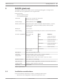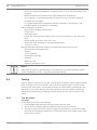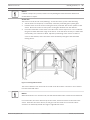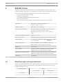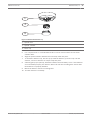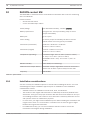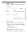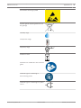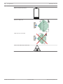
1
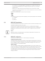
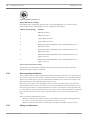
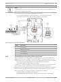
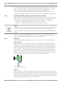
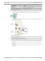
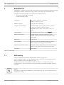
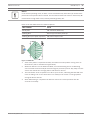
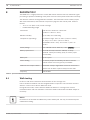
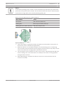
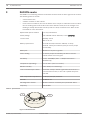
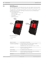
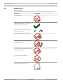
RADION receiver OP
RFRC-OPT
en
Reference Guide
RADION receiver OP
Table of Contents | en
3
Table of contents
1
Introduction
5
1.1
About documentation
5
1.2
Bosch Security Systems, Inc. product manufacturing dates
5
2
General installation
7
2.1
Installation workflow
7
2.2
Unpacking information
8
2.3
Wall tamper switch installation
8
2.4
Magnet cover installation
8
2.5
Complete installation
8
2.6
Maintenance
9
3
RADION receiver OP
10
3.1
Certifications and approvals
10
3.2
RFRC-OPT Installation
11
3.2.1
RFRC-OPT configuration
11
3.2.2
Base mounting installation
12
3.2.3
Wiring considerations
12
3.2.4
Programming wireless points in the control panel
13
3.2.5
Enroll point RF ID for wireless points (Auto-learn mode)
14
3.2.6
Walk test
14
3.2.7
Complete the installation
15
3.2.8
RFRC-OPT system test
15
3.3
External LED states
15
3.4
Specifications (RFRC-OPT)
16
3.4.1
Battery requirements
17
4
RADION repeater
19
4.1
Installation considerations
19
4.2
Wiring considerations
19
4.3
Specifications
20
4.4
LEDs
20
5
RADION glassbreak
21
5.1
Installation considerations
21
5.2
Testing
22
5.2.1
Test the sensor
22
5.2.2
Hand clap test
24
5.3
Low battery
24
5.4
Wall Tamper Tab
24
5.5
Maintenance
24
6
RADION TriTech
25
6.1
Mounting height and range adjustment
25
6.2
Sensitivity settings
26
6.2.1
Standard sensitivity
26
6.2.2
Intermediate sensitivity
26
6.3
Walk testing
26
7
RADION PIR
28
7.1
Walk testing
28
8
RADION PIR C
30
8.1
Walk testing
30
Bosch Security Systems, Inc
Reference Guide
02.2014 | 01 | F.01U.261.835
4
en | Table of Contents
RADION receiver OP
9
RADION smoke
32
9.1
Battery replacement
33
9.2
Smoke test
33
9.3
Sensitivity test
33
9.4
Test/Silence button
34
9.5
LED
34
9.6
Clean the detector and replace the optical chamber
34
10
RADION contact SM
36
10.1
Installation considerations
36
11
RADION contact RM
38
11.1
Installation considerations
38
12
RADION specialty
40
12.1
Applications for this product
40
12.2
Installation consideration
41
13
RADION universal transmitter
42
13.1
Installation considerations
43
13.2
Reed switch settings
43
14
RADION keyfob
45
14.1
RADION keyfob FB
45
14.2
RADION keyfob TB
46
15
RADION panic
48
16
Appendices
50
02.2014 | 01 | F.01U.261.835
Reference Guide
Bosch Security Systems, Inc
RADION receiver OP
1
Introduction | en
5
Introduction
This document contains the basic information that a trained installer needs to install the
RADION system. It supplements the documents listed inside the packaging (graphical
installation guides).
This reference guide contains:
–
A description of the general installation procedure.
–
Device-specific installation procedures.
–
Specification information.
How to use this document
The information contained in this document is constructed in a manner that is systematic and
sequential for the installer on a “point of need” basis. The following represents a basic outline
of that information;
–
Chapter 1 (this chapter) – introductory information and how to use this document.
–
Chapter 2 – basic RADION system-wide general installation information and workflow
check list.
–
Chapter 3 – RADION receiver-specific installation information.
–
Remaining chapters – RADION device-specific installation information.
–
Appendix – description of various icons and symbols used within the RADION
documentation.
Icons and symbols
When you see the following logo in the RADION graphical installation guides listed in Table
3.1, refer to the appropriate section in this document.
Additional icons and symbols, which appear in the RADION graphical installation guides, are
explained in the appendix section of this guide. Refer to the Appendices, page 50 for more
information.
1.1
About documentation
Copyright
This document is the intellectual property of Bosch Security Systems, Inc. and is protected by
copyright. All rights reserved.
Trademarks
All hardware and software product names used in this document are likely to be registered
trademarks and must be treated accordingly.
1.2
Bosch Security Systems, Inc. product manufacturing dates
Use the serial number located on the product label and refer to the Bosch Security Systems,
Inc. website at http://www.boschsecurity.com/datecodes/.
The following image shows an example of a product label and highlights where to find the
manufacturing date within the serial number.
Bosch Security Systems, Inc
Reference Guide
02.2014 | 01 | F.01U.261.835
6
en | Introduction
02.2014 | 01 | F.01U.261.835
RADION receiver OP
Reference Guide
Bosch Security Systems, Inc
RADION receiver OP
2
General installation | en
7
General installation
Phases of installation
The installation of the RADION system is achieved by following the sequential process as
defined in this chapter. Overall, there are four main phases;
–
Planning
–
Physical installation of the devices
–
System enrollment/configuration
–
System testing (walk test, pattern test)
It is essential that these steps or phases are adhered to in the order mentioned above for
proper functionality and operation.
When installing a RADION system, you must plan your installation based on the control panel
and RADION device specifications, and the radio-frequency signal strength (RFSS) between
devices, receivers, and control panels.
Installation considerations
–
RADION devices are intended only for indoor, dry applications.
–
Mount RADION devices on flat, rigid surfaces. Some devices can be optionally corner
mounted as indicated in the installation instructions.
–
Avoid mounting RADION devices in areas with large, metallic objects, electrical panels, or
electric motors. They might reduce the radio-frequency (RF) range of a RADION device.
–
Avoid installing the devices where excessive humidity, moisture, or temperatures outside
of the acceptable operating range exist.
–
Wire all objects according to their specifications.
–
RADION devices use batteries of varying types. When installing batteries, observe safety
and polarity recommendations as indicated in the documentation for those products.
2.1
Installation workflow
To install, configure, and test the system, use the workflow below and follow in sequential
order, from top to bottom, checking each box as you complete a step.
Notice!
Always power down the control panel when connecting modules, or other wiring. Power
down the control panel by unplugging the transformer and disconnecting the battery
Plan the installation of the RADION system
Install the RADION components (refer to the graphical installation guides and this system
reference guide for details)
Program wireless points in the control panel
Enroll point RF ID for wireless points
Verify LED responses on devices
Perform a local walk test for installed detectors
Review signal strength and margin of each point
Complete the installation
Bosch Security Systems, Inc
Reference Guide
02.2014 | 01 | F.01U.261.835
8
2.2
en | General installation
RADION receiver OP
Unpacking information
When unpacking the receiver, repeater, or bill trap device, it is important to remove the
cardboard insert as illustrated below;
Figure 2.1: Insert for the receiver and repeater
Figure 2.2: Insert for the bill trap
2.3
Wall tamper switch installation
RADION transmitter devices contain a feature that activates the wall tamper switch located on
the base of the device. In order to properly install the device, you must consider the following:
–
To properly install a device with active wall tamper functionality, insert a screw in the
designated screw slot location.
–
Failure to insert a screw into the wall tamper slot prevents the wall tamper feature from
generating a tamper signal when the transmitter is pulled away from a wall.
2.4
Magnet cover installation
During the installation of the plastic magnet cover, the cover is not designed to be separated
from the base after the base and cover are snapped together. Damage to the plastics may
occur if separated.
2.5
Complete installation
Testing the entire RADION system can only be achieved by performing an area wide test
through the control panel and corresponding keypad(s). This is achieved by performing an
overall service walk test. Refer to your control panel documentation for system-walk, or other
system-wide testing procedures.
02.2014 | 01 | F.01U.261.835
Reference Guide
Bosch Security Systems, Inc
RADION receiver OP
General installation | en
9
To ensure proper operation of the RADION devices, test the basic functionality of the device
locally. Depending on the RADION device to be tested, perform the following procedures for
functionality:
–
When testing the receiver, power up the compatible control panel in which the receiver is
connected to and observe the LED behavior on the receiver.
–
Local walk testing can be performed on the motion detectors as defined in the tritech
and PIR chapters of this guide.
–
Magnet testing can be performed by opening or closing the door/window in which the
magnet is installed on.
2.6
Maintenance
It is recommended to check the battery of each device annually. This will ensure proper
operation and functionality of the devices.
Battery Life Extension feature (PIR and TriTech)
In the normal operating mode, an alarm can be transmitted only after three (3) minutes have
passed since the previous alarm restoral. This 3 minute lockout time reduces unnecessary RF
transmissions in high traffic areas, thereby extending battery life.
Bosch Security Systems, Inc
Reference Guide
02.2014 | 01 | F.01U.261.835
10
en | RADION receiver OP
3
RADION receiver OP
RADION receiver OP
RADION receiver OP is a wireless receiver that connects RADION wireless peripherals to
supported Bosch option bus control panels via the terminal block connection. A compatible
control panel powers the receiver through the wiring connection. Features include:
–
Easy addressing via a rotary switch
–
Cover and wall tamper protection
–
RFID and configuration data are contained in persistent memory
–
External LEDs
–
Detection and reporting of radio frequency interference
Notice!
The Option Bus receiver does not support key fob supervision
Use this reference guide along with the control panel’s documentation and each device’s
installation instructions to complete the installation process.
Product
Description
Document
RFRC-OPT
RADION receiver OP
Graphical installation guide (P/N: F01U261830)
RFBT
RADION specialty
Graphical installation guide (P/N: F01U261814)
RFDL-11
RADION TriTech
Graphical installation guide (P/N: F01U261815)
RFDW-RM
RADION contact RM
Graphical installation guide (P/N: F01U291208)
RFDW-SM
RADION contact SM
Graphical installation guide (P/N: F01U261817)
RFKF-TB/RFKF-FB
RADION keyfob
Graphical installation guide (P/N: F01U261820)
RFPB-SB/RFPB-TB
RADION panic TB
Graphical installation guide (P/N: F01U261821)
RFPR-12
RADION PIR
Graphical installation guide (P/N: F01U261822)
RFPR-C12
RADION PIR C
Graphical installation guide (P/N: F01U261823)
RFRP
RADION repeater
Graphical installation guide (P/N: F01U261824)
RFSM
RADION smoke
Graphical installation guide (P/N: F01U261825)
RFGB
RADION glassbreak
Graphical installation guide (P/N: F01U261818)
RFUN
RADION universal
Graphical installation guide (P/N: F01U261826)
Table 3.1: RADION Wireless products
3.1
Certifications and approvals
Listings and approvals
Europe
The RFRC-OPT is EN listed for EN50131-3: 2009, EN50131-5-3: 2005 + A1: 2008, and
EN50130-5 Environmental Class II.
As a manufacturer of batteries or devices containing batteries, we are obliged to inform you of
the following in accordance with the Battery Ordinance:
–
02.2014 | 01 | F.01U.261.835
Batteries must not be disposed of in household waste.
Reference Guide
Bosch Security Systems, Inc
RADION receiver OP
RADION receiver OP | en
11
–
As a consumer, you are legally obliged to take batteries to a suitable collection point.
–
You can return used batteries free of charge to the point of sales or to a communal
–
Batteries can contain substances that are hazardous to the environment or health.
–
Only dispose of discharged batteries in the container provided and, in the case of lithium
collection point.
batteries, mask the poles.
Batteries are identified with a crossed out trash can symbol.
If the batteries contain specific harmful substances, the chemical symbols are also indicated:
3.2
–
Cd - Cadmium
–
Pb - Lead
–
Hg - Mercury
RFRC-OPT Installation
Use the provided anchors and screws to mount the receiver in locations accessible for future
maintenance. Mount the receiver onto a wall.
For best receiver reception results, place the receiver in a central location among the
transmitters. For optimal communication results in situations where there is a long distance
between the transmitting device and the system receiver, it might be necessary to install
repeaters.
Notice!
Mount the receiver in a location away from metal objects. Metal objects (duct work, wire
mesh screens, boxes) reduce RF range.
3.2.1
RFRC-OPT configuration
RADION Wireless System operates on a radio frequency of 433.42 MHz.
Configuring the address switch
The address switch determines the receiver’s numeric address value which the receiver will
use to report receiver status information to the control panel. Set the address to the receiver
prior to installation. Address 1 through 8 are valid address settings for the receiver. Use a
slotted screwdriver to set the address switch.
Address settings
The receiver address switches provide a single-digit setting for the receiver’s address. The
receiver uses addresses 1 through 8. Addresses 0 and 9 are invalid and will cause the receiver
to enter into an Option bus communication error state. This will cause the receiver to be
unrecognized by the control panel. Refer to your control panel documentation for information
on the valid addresses for that control panel. The figure below shows the address switch
setting for address 1.
Bosch Security Systems, Inc
Reference Guide
02.2014 | 01 | F.01U.261.835
12
en | RADION receiver OP
RADION receiver OP
Figure 3.1: Address switch set to 1
Option Bus address settings
Depending on the supporting control panel, use the following table as a reference when
selecting the address setting switch for the compatible control panel.
Address switch setting
Function
1
RADION receiver 1
2
RADION receiver 2
3
Legacy Mode receiver 1
4
Legacy Mode receiver 2
5
Maintenance Mode, EN50131 Grade 2 (6dB attenuation), for
RADION receiver 1
6
Maintenance Mode, EN50131 Grade 2 (6dB attenuation), for
RADION receiver 2
7
Maintenance Mode, EN50131 Grade 2 (6dB attenuation), for
legacy receiver 1
8
Maintenance Mode, EN50131 Grade 2 (6dB attenuation), for
legacy receiver 2
Table 3.2: Option Bus address settings
The receiver and control panel establish communication between each other when the
appropriate address switch is selected.
3.2.2
Base mounting installation
Some consideration and planning are required when locating a position to mount the base of
the receiver onto the desired surface. The base must be mounted in such a way that provides
plenty of accessible space to insert a flat-headed screwdriver, and remove the receiver cover
when maintenance and troubleshooting scenarios occur.
Because of the location of the opening mechanism on the side of the device, you will need
approximately 254 mm (10 in) of clearance on one side of the base to provide easy access to
the opening mechanism, and approximately 15 mm (0.6 in) of clearance on the opposite side
to compensate for the physical dimensions of the device cover. This should allow for adequate
space in which the device cover can be opened, and the cover removed, should the need
arise.
Other mounting considerations include;
–
Minimum clearance above the location to compensate for the vertical sliding movement
–
Minimum clearance below the location where the base is mounted: >23 mm (0.9 in).
to attach or remove the device from the base is: >30 mm (1.2 in).
3.2.3
Wiring considerations
02.2014 | 01 | F.01U.261.835
Reference Guide
Bosch Security Systems, Inc
RADION receiver OP
RADION receiver OP | en
13
Notice!
Do not install long cable runs next to high-current power feeds. Keep cable lengths as short
as possible to minimize noise pickup.
Ensure that the wiring used meets the following specifications:
–
Four-conductor unshielded 0.65 mm (22 AWG) to 2.0 mm (18 AWG) maximum.
–
Wire length must not exceed 300 m (1000 ft) from the control panel
Figure 3.2: Wiring to an Option Bus Terminal Strip
3.2.4
Callout
Description
1
Control Panel
2
RADION receiver OP
3
Terminal Block
4
Terminal Wiring
Programming wireless points in the control panel
After completing the physical installation of the RADION system, you must configure the
RADION points in order to establish communication between the RADION system and the
supported Option bus control panel. This can be accomplished by using one of two methods:
–
Using remote programming software on a supported laptop computer, or
–
Compatible keypad devices to enable your points
A “point” can be a detection device, or a group of devices connected to your security system.
The first step to enable communication is to verify that the RADION transmitter is
programmed into the supporting control panel. This is achieved by configuring a point source
index as wireless, and then associating a transmitter’s RFID with that point source index
RFID programming from a supported keypad is achieved by two methods;
–
Through the point source/RFID menu options, or
–
Enroll point RFID for wireless points – which uses the “Auto-Learn” methodology
Bosch Security Systems, Inc
Reference Guide
02.2014 | 01 | F.01U.261.835
14
en | RADION receiver OP
RADION receiver OP
The preferred method of entering in the RFID number would be to enter it in manually via the
keypad – point source/RFID, or remote programming software. Doing so gives you greater
control and security, while reducing the risk of incomplete RFID programming.
For more information on programming wireless points in the control panel, refer to the
Installation and Operation manual of the compatible control panel on registering the receiver.
3.2.5
Enroll point RF ID for wireless points (Auto-learn mode)
A second RFID Programming option exists whereby new devices are “Auto Learned” on the
system. Auto Learn Mode is the process through which the control panel identifies and enrolls
new device RF ID’s that appear within the system. This is achieved by the following:
–
Keyfobs – when the keyfob buttons are pressed, then released.
–
Detectors – when the battery is inserted, or if the detector is faulted.
Notice!
The Auto Learn mode option is not recommended as the preferred method of entering in the
RF ID’s due to the potential of the RADION system picking up the first available RF ID it
detects. For optimal results, manually enter in the RF ID’s through the supported keypad, or
via RPS.
For more information on enrolling RF ID’s in the control panel, refer to the Installation and
Operation manual of the compatible control panel on enrolling RF ID‘s.
3.2.6
Walk test
Use the following pattern testing procedure to test the detector range and functionality.
Motion walk test
Remove and replace cover to activate a 90-sec Walk Test Mode. During this Test Mode, any
activity in the sensor’s coverage pattern will cause a transmitted alarm and LED activation.
Each alarm will also extend the Test Mode for an additional 90-sec. Walk Testing should be
done across the coverage pattern. The edge of the coverage pattern is determined by the first
flash of the LED. This may change slightly depending upon the sensitivity setting. Walk Test
the unit from both directions to determine the pattern boundaries. Although generally not
required, if masking is desired, the lens diagram shows the appropriate areas to be masked.
Use an opaque material (such as, electrical tape) to mask the desired areas.
90 sec
Figure 3.3: 90 sec walk test
Final test
While the detector is in the Walk Test Mode, turn on all heating and air conditioning sources
which would normally be active during the protection period. Stand away from the sensor and
outside the coverage pattern and watch for alarms. After setup and tests are completed, and
there has been no activity in the sensor’s coverage pattern for approximately 90-sec, the LED
will flash to indicate that the Walk Test mode is ending.
02.2014 | 01 | F.01U.261.835
Reference Guide
Bosch Security Systems, Inc
RADION receiver OP
RADION receiver OP | en
15
Maintenance
At least once a year, a walk test should be performed to verify the range and coverage for
proper operation.
Magnet walk test
Perform a magnet test to ensure proper functionality of the door and window contacts.
Magnet testing can be performed by opening or closing the door/window in which the magnet
is installed. In this test, you are verifying the distances of which the magnet engages and
disengages the transmitter.
3.2.7
Complete the installation
Depending on the results of testing the RADION system from a system-wide approach (walk
test, signal strength and margin tests), make the appropriate modifications/adjustments to
complete the install process.
3.2.8
RFRC-OPT system test
Overall system test
It is recommended by to test the entire system at least once every year, including the RFRCOPT receiver by an installer to ensure proper functionality of the RADION system.
3.3
External LED states
The receiver utilizes the External LED to show various states of the receiver. These states fall
into the following three categories:
–
Normal state
–
Communication error state
–
Trouble state
–
Maintenance state
–
Off state
Normal state:
The receiver enters a normal state when it has passed all power self-tests and has established
a communication link with the control panel . The receiver remains in this state as long as the
communication link is present, and no other issues are present that would prevent the
receiver from operating in a normal condition.
LED condition
State description
On (Normal)
Indicates the receiver is functioning normally.
Continuous slow flash: 1 sec On, 1 sec Off
Indicates the receiver is being programmed
with the zone and transmitter ID’s from the
compatible control panel.
Turns Off momentarily
Indicates the receiver obtained a valid
transmission from a RADION transmitter.
Flash 3 times
Indicates the receiver has obtained a new
device ID while in “Learn Mode.”
Bosch Security Systems, Inc
Reference Guide
02.2014 | 01 | F.01U.261.835
16
en | RADION receiver OP
RADION receiver OP
Communication error state:
The receiver enters a communication error state when, during power up, it does not establish
a link with the control panel, or has been in an idle state for more than 30 sec without
communication. Another cause for a communication error state is an invalid address switch
setting (0, or 9).
LED condition
State description
3-pulse flash: A 3-pulse signal, followed by a
Indicates the receiver has experienced a
short delay at the end of the 3 pulse
communication failure. This error could be a
(Communication error)
result of either:
rd
–
A communication failure between the
control panel and receiver, or
–
An invalid address switch setting
Trouble state:
The receiver enters a trouble state when an internal self-test detects a failure. Another cause
for the receiver entering into a trouble state would be if the receiver detects radio frequency
interference failure.
LED condition
State description
Continuous fast flash: A continuous pulse
–
between On and Off states (Trouble state)
Indicates the receiver is in a trouble
state, experiencing a radio frequency
interference failure
–
A communication failure with internal
hardware components within the
receiver
Maintenance state
The receiver enters a maintenance state when the address switch settings are set between
switch 5 – switch 8.
LED condition
State description
Continuous Flash: A continuous pattern of
Indicates the receiver is in Maintenance
short off time, followed by long on time.
Mode.
Off state
Indicates there is a power failure to the receiver. Check the wire connections for proper
wiring.
3.4
Specifications (RFRC-OPT)
Housing Dimensions (H x W x D)
139.7 mm x 209.6 mm x 31.8 mm (5.5 in x
8.25 in x 1.25 in)
Power/Voltage
12 VDC nominal
Maximum Current Draw
100 mA
Operating Environment
Functional range: -10°C to +49°C (+14°F to
+120°F)
EN 50130-5 Class II only: -10゚C to 40゚C (+14゚
F to +104゚F
02.2014 | 01 | F.01U.261.835
Reference Guide
Bosch Security Systems, Inc
RADION receiver OP
RADION receiver OP | en
Relative Humidity
Up to 93% non-condensing
Frequency
433.42 MHz
Wiring Distance
Maximum distance of 300 m (1000 ft) from
17
the control panel
Wiring Gauge
0.65 mm (22 AWG) to 2.0 mm (18 AWG)
maximum
Wall and Cover Tamper Switch
–
Transmits a tamper signal when the
device is removed from its base or
pulled away from the wall
Table 3.3: RFRC-OPT Specifications
3.4.1
Battery requirements
Notice!
Dispose of used batteries according to manufacturer’s instructions.
RADION Device
Battery Size
Battery Type
Cell Voltage
Quantity
(Cells)
RFPR-12 PIR
CR123A
Lithium
3 VDC
1
CR123A
Lithium
3 VDC
1
Non-
Lithium polymer
3.7 VDC nominal
1
CR123A
Lithium
3 VDC
2
CR123A
Lithium
3 VDC
1
AAA
Lithium
1.5 VDC
1
AA
Alkaline
1.5 VDC
4
AAA
Lithium
1.5 VDC
1
AAA
Lithium
1.5 VDC
1
CR123A
Lithium
3 VDC
1
motion detector
RFPR-C12 PIR
motion detector
(curtain)
RFRP repeater
replaceable
RFSM smoke
detector
RFUN universal
transmitter
RFBT bill trap
RFDL-11 TriTech
detector
RFDW-SM standard
door/window
contact
RFDW-RM
recessed door/
window contact
RFGB glassbreak
Bosch Security Systems, Inc
Reference Guide
02.2014 | 01 | F.01U.261.835
18
en | RADION receiver OP
RADION Device
RADION receiver OP
Battery Size
Battery Type
Cell Voltage
Quantity
(Cells)
RFKF-TB key fob
CR2032 (coin
RFKF-FB-key fob
cell)
RFPB-SB- panic
CR2032 (coin
button
Lithium
3 VDC
1
Lithium
3 VDC
1
cell)
RFPB-TB- panic
button
Table 3.4: Battery Requirements
02.2014 | 01 | F.01U.261.835
Reference Guide
Bosch Security Systems, Inc
RADION receiver OP
4
RADION repeater | en
19
RADION repeater
The RFRP is a combined receiver and transmission device that improves the overall
transmission, communication, and reliability capabilities of its assigned compatible receiver.
An LED on the front provides device status.
Features include:
–
LED Display
–
Cover and Wall Tamper protection
Notice!
The repeater is designed to improve the communication performance of the RADION wireless
portfolio, and not to extend the range of the wireless devices. Install the transmitters within
the suggested range for optimal performance and reliability.
Notice!
Use a supported transformer as defined in the specification table for the repeater. Do not
connect power supply to a receptacle controlled by a switch.
4.1
Installation considerations
Use the provided anchors and screws to mount the repeater in locations accessible for future
maintenance. Mount the repeater onto a wall.
Notice!
Mount the repeater in a location removed from metal. Metal objects (duct work, wire mesh
screens, boxes) reduce RF range
4.2
Wiring considerations
Notice!
Do not install long cable runs next to high-current power feeds. Keep cable lengths as short
as possible to minimize noise pickup.
Ensure that the wiring used meets the following specifications:
–
Two-conductor unshielded wire.
–
The minimal requirement for wire length is 1.83 m (6 ft) from the repeater
Bosch Security Systems, Inc
Reference Guide
02.2014 | 01 | F.01U.261.835
20
en | RADION repeater
4.3
RADION receiver OP
Specifications
Dimensions
139.70 mm x 209.60 mm x 31.80 mm
(5.50 in x 8.25 in x 1.25 in)
Power/Voltage
16.5 VAC, 40VA (~)
(Standby battery)
Rated 3.7 VDC, 3050mAH EVE ENERGY CO Part No P0046-LF (Not user
replaceable). For standby battery to be operative, the tamper switch is
required to be engaged.
Transformer power/voltage
Must meet country specific requirements
Current Draw
60 mA
Wire Gauge
0.65 mm (22 AWG) to 2.0 mm (18 AWG)
Temperature (operating)
0゚C to +49゚C (+32゚F to+120゚F)
Relative Humidity
0% to 93% (non-condensing)
Device testing
To ensure proper functionality, the device must be tested at least once
every year by an installer.
Wall and Cover Tamper Switch Transmits a tamper signal when someone removes the device from its
base or pulls it away from the wall.
Frequency
433.42 MHz
Table 4.1: Specifications
4.4
LEDs
The repeater utilizes an external LED indicator to status the operation of the repeater. Refer to
the table below for LED descriptions.
LED Condition
Pattern Description
On (Normal)
–
Indicates the repeater is functioning normally.
Off
–
Indicates there is a power failure to the repeater, or that the
receiver is not wired correctly.
Continuous Flash: 1 sec
–
rate for 5 sec
Continuous Flash: A 3-
Indicates the repeater is being powered up, and conduction
manufacturing test initializations.
–
pulse signal, followed by
Indicates the repeater has experienced a low battery
condition.
a short delay after the 3rd
pulse
Continuous Flash: A 2
–
Indicates an AC power failure is detected.
flash pattern continuous
–
A communication failure within internal hardware
pulse between On and
components inside the receiver
Off states with a short
delay after the 2nd pulse
02.2014 | 01 | F.01U.261.835
Reference Guide
Bosch Security Systems, Inc
RADION receiver OP
5
RADION glassbreak | en
21
RADION glassbreak
The RFGB is a wireless transmitter used for detecting breaking glass. Throughout this
document, the term “glassbreak” refers to glass break.
Features include:
–
Monitored battery status
–
Four sensitivity settings
Dimension
101.42 mm x 112.90 mm x 35.00 mm
(3.99 in x 4.44 in x 1.38 in)
Power/Voltage
Battery/CR123A, 3 VDC (
)
Battery replacement
Duracell DL123A, Lithium, Panasonic CR123A Lithium, or Sanyo
CR123A Lithium. Check your battery yearly to ensure proper
functionality.
Battery life
Up to 5 years
Device testing
To ensure proper functionality, the device must be tested at least
once every year.
Accoustic Capabilities Glass types and
thickness
Type
Thickness
Plate
2.4 mm to 6.4 mm
(3/32 in to 1/4 in)
Tempered
3.2 mm to 6.4 mm
(1/8 in to 1/4 in)
Laminated
3.2 mm to 6.4 mm
(1/8 in to 1/4 in)
Wired
6.4 mm (1/4 in)
Minimum pane size for all 1.2 m (4 ft)
types of glass
Microphone
Omni-directional 360゚ electret
Operating
Functional range: -10°C to +49°C (+14°F to +120°F)
Temperature
UL only: 0゚C to +49゚C (+32゚F to+120゚F)
EN 50130-5 Class II only: -10゚C to 40゚C (+14゚F to +104゚F
Relative Humidity
0% to 93% (non-condensing)
Wall and Cover
Transmits a tamper signal when someone removes the device from
Tamper Switch
its base or pulls it away from the wall.
Frequency
433.42 MHz
Table 5.1: Specifications
5.1
Installation considerations
For the best detector performance, select a mounting location that is:
–
Bosch Security Systems, Inc
Mounted on the ceiling within a maximum range of 20 ft (6 m)
Reference Guide
02.2014 | 01 | F.01U.261.835
22
en | RADION glassbreak
–
RADION receiver OP
For armor-coated glass installations, mount the sensor no more than 12 ft (3.65 m) from
the glass
–
Mount the detector in the direct line of sight of the glass to be protected
–
On an opposite, or adjoining wall, within a range of 20 ft (6 m) for plate, tempered,
–
In a suitable environment: temperature between -18 and 50゚C (0 and 120゚F); and
laminated, and wired glass
humidity between 10 and 90% non-condensing
Avoid mounting the detector in:
–
Glass airlocks and glass vestibule areas
–
Humid rooms
–
Small utility rooms
–
Rooms with noisy equipment (white noise) such as air compressors, bells, and power
tools
–
Rooms smaller than 10 ft x 10 ft (3 m x 3 m)
–
Rooms with lined, insulating, or sound deadening drapes
–
A corner of a room
Avoid locations that expose the detector to possible false-alarm sources such as:
–
Glass airlocks and vestibule areas;
–
Kitchens;
–
Corner mounting;
–
Residential car garages;
–
Stairwells
–
Bathrooms; and
–
Small acoustically live rooms
Notice!
Glass break detectors are intended only as a component of a perimeter protection system.
They should always be used in conjunction with motion sensors.
5.2
Testing
Test the detector at least once each year. Test the detector with the Sentrol 5709C hand-held
tester to set the sensor into test mode. Set the tester to tempered glass, hold the speaker
directly on top of the sensor, and activate the tester. The sensor alarms, and then goes into
test mode for one minute. When in test mode, the LED on the sensor blinks continuously.
Extend the test mode time by holding the speaker directly over the sensor at least once a
minute.
5.2.1
Test the sensor
Test mode
To test the sensor, perform the following:
1.
Use the 5709C hand-held tester to put the sensor into test mode
2.
Set the tester to tempered glass and hold the tester on top of the sensor.
3.
Activate the tester. The sensor alarms and goes into test mode for one minute. During
test mode, the LED blinks continuously. To extend test time, fire the tester at the sensor
at least once a minute.
02.2014 | 01 | F.01U.261.835
Reference Guide
Bosch Security Systems, Inc
RADION receiver OP
RADION glassbreak | en
23
Notice!
If blinds or drapes are present, test the area by holding the hand-held tester behind the
closed blinds or drapes.
Sensor test
The sensor must be in test mode (blinking). To test the sensor, perform the following:
1.
Set the tester for tempered, or laminated, unless the protected glass is plate glass.
2.
Hold the tester near the surface of the glass to be protected and aim the speaker at the
sensor. Be sure the tester is at the point on the glass farthest from the detector.
3.
Press the test button on the tester. The LED on the sensor stays on for 4 sec to indicate
the glass is within detection range of the sensor. If the LED does not stay in a solid state
momentarily, but continues to blink, adjust the positioning of the sensor so that it is
closer to the window, and re-test. Also check the battery strength of the hand-held
testing device.
Figure 5.1: Testing behind curtains
The sensor switches from test mode to normal mode when there is at least 1 min of silence
from the hand-held tester.
Notice!
When the detector is in normal mode, the LED will not blink unless a loud sound is detected.
In normal mode, the sensor will not trip to the tester, unless the tester is held next to the
sensor. Each time the sensor alarms, it also goes into test mode for one minute. Room
acoustics can artificially extend the range of a glassbreak sensor.
Bosch Security Systems, Inc
Reference Guide
02.2014 | 01 | F.01U.261.835
24
en | RADION glassbreak
RADION receiver OP
The specified range of the sensor has been established for worst-case conditions. While the
sensor will likely function at additional range, it may miss a minimum output break, or room
acoustics may change at some future time, bringing the sensor range back into normal 20 ft.
(6 m) conditions. Do not exceed the rated range of the sensor, regardless of what the tester
shows.
5.2.2
Hand clap test
Operational status of the glassbreak can be verified by performing a simple hand clap test to
ensure proper functionality of the sensor.
Performing the hand clap:
1.
Hand clap loudly under the sensor. The LED blinks twice.
2.
Verify that the LED blinks twice.
3.
Performing this simple test verifies that the microphone is operating, and that there is
power to the sensor.
5.3
Low battery
When a low battery state is detected, the detector measures the battery, and sends a report
to the receiver/control panel.
5.4
Wall Tamper Tab
Use the wall tamper tab to activate an alarm when the glass break has been removed from the
wall.
5.5
Maintenance
Clean the cover with a damp (water) cloth as needed to keep it free of dust and dirt. Always
test the sensor after cleaning it.
02.2014 | 01 | F.01U.261.835
Reference Guide
Bosch Security Systems, Inc
RADION receiver OP
6
RADION TriTech | en
25
RADION TriTech
The RFDL-11 is a motion detector which uses artificial intelligence to detect motion and
provide immunity to false alarms. An integral RF transmitter reports low battery and tamper
status, and sends a supervisory signal to the control panel. Features include:
–
11m x 11m (35 ft by 35 ft) coverage
–
Flexible mounting height
–
Compatible with Bosch RADION wireless systems
–
Draft and Insect immune
–
Cover activated tamper indication. Optional wall-activated tamper is included
Dimension
138.00 mm x 72.00 mm x 64.00 mm
(5.43 in x 2.83 in x 2.52 in)
Relative humidity
0% to 93%, (non-condensing)
Temperature (operating)
Functional range: -10°C to +49°C (+14°F to +120°F)
UL only: 0゚C to +49゚C (+32゚F to+120゚F)
EN 50130-5 Class II only: -10゚C to 40゚C (+14゚F to
+104゚F
Internal coverage directionality
Vertical: -4゚ to -10゚
Sensitivity selection
Field selectable for standard or intermediate sensitivity
Power/voltage
Four AA Alkaline batteries, 1.5 VDC (
). 1.5 VDC
x 4 = 6 VDC total.
Battery replacement
Duracell MN1500, Panasonic AM-3PIX. Check your
battery yearly to ensure proper functionality.
Battery life
Up to 5 years
Device testing
To ensure proper functionality, the device must be
tested at least once every year by an installer.
Wall and cover tamper switch
Transmits a tamper signal when someone removes the
device from its base or pulls it away from the wall.
Frequency
433.42 MHz
Table 6.1: Specifications
6.1
Mounting height and range adjustment
Loosen the vertical adjustment screw. Adjust the board to the desired angle. Choose mounting
height and desired range, and set the vertical angle. Reference the table below for proper
height and adjustment values.
Mounting height
Range
6.1 m (20 ft)
10.7 m (35 ft)
-7゚
-5゚
2 m (6.5 ft)
Bosch Security Systems, Inc
Reference Guide
02.2014 | 01 | F.01U.261.835
26
en | RADION TriTech
RADION receiver OP
2.1 m (7.0 ft)
-9゚
-6゚
2.4 m (8.0 ft)
-10゚
-7゚
Notice!
The mounting height must be 2 m (6.5 ft) and the vertical angle must be set at -5゚ for
installations containing pets.
The vertical adjusting screw must be securely tightened after setting the angle.
6.2
Sensitivity settings
6.2.1
Standard sensitivity
Use this setting when pets are present in the monitored area. Standard sensitivity provides
excellent detection performance and is the least sensitive to false alarms.
6.2.2
Intermediate sensitivity
Only use this setting in non-pet installations with minimal environmental disturbances.
Intermediate sensitivity provides the highest level of detection performance.
6.3
Walk testing
Notice!
To maximize battery life, the LED elements do not activate unless the unit is in the Walk Test
mode.
Perform a walk test to determine the boundaries of the coverage area. Perform this test at the
time of installation and monthly thereafter. To ensure continual daily operation, instruct the
end user to walk through the far end of the coverage pattern. This ensures an alarm output
prior to arming the system.
Start Walk Test mode from the detector. Insert a slotted screwdriver to open the detector
cover and then close the detector cover to start a 90-sec Walk Test mode.
Notice!
In the normal operating mode, an alarm can be transmitted only after three (3) minutes have
passed since the previous alarm restoral. This 3 minute lockout time reduces unnecessary RF
transmissions in high traffic areas, thereby extending battery life.
During this test mode, motion detected within the detector’s coverage area causes a
transmitted alarm and LED activation. Each alarm will also extend the Test Mode. Watch for
the green LED to indicate the edges of the Microwave pattern. Adjust as necessary.
Please reference the LED table below for LED descriptions.
LED Condition
Cause
Steady LED
PIR activation (Walk Test)
Steady green
Microwave activation
Steady blue
Alarm signal
02.2014 | 01 | F.01U.261.835
Reference Guide
Bosch Security Systems, Inc
RADION TriTech | en
RADION receiver OP
LED Condition
Cause
Flashing blue
Warm-up period after power-up
No LED upon initial power up
PIR failure. Replace unit.
27
Walking Testing the system
1.
Start at the pattern’s expected boundary and walk across the pattern moving closer to
the detector. Set the adjustment as low as possible for proper catch performance.
2.
Adjust the Microwave Range Adjustment Potentiometer to as low a setting as possible for
proper catch performance.
Figure 6.1: Sensitivity settings
1 ᅳ Alarm LED (blue, green, or red)
2 ᅳ Microwave Range Adjustment Potentiometer
3.
At each pass, observe the color on the Alarm LED (refer to the Sensitivity settings figure
above).
4.
Walk test from the opposite direction to determine the coverage pattern boundaries from
both sides.
5.
When walk test is completed, the detector returns to normal operation after 90 sec of
inactivity.
Bosch Security Systems, Inc
Reference Guide
02.2014 | 01 | F.01U.261.835
28
7
en | RADION PIR
RADION receiver OP
RADION PIR
The RFPR-12 is a high performance PIR motion detector that uses advanced signal processing.
An integrated wireless transmitter sends a battery report with each transmission, and
transmits a supervisory signal to the control panel. Features include:
–
12 m x 12 m (40 ft x 40 ft) coverage
–
Flexible Mounting Height
Dimensions
111.00 mm x 60.00 mm x 43.00 mm
(4.40 in x 2.40 in x 1.70 in)
Relative humidity
Up to 93%, non-condensing
Temperature (operating)
Functional range: -10°C to +49°C (+14°F to +120°F)
UL only: 0゚C to +49゚C (+32゚F to+120゚F)
EN 50130-5 Class II only: -10゚C to 40゚C (+14゚F to
+104゚F
Power/voltage
One CR123A Lithium battery, 3 VDC (
)
Battery replacement
Duracell DL123A , Panasonic CR123A, or Sanyo
CR123A. Check your battery yearly to ensure proper
functionality.
Battery life
Up to 5 years
Device testing
To ensure proper functionality, the device must be
tested at least once every year by an installer.
Wall and cover tamper switch
Transmits a tamper signal when someone removes the
device from its base or pulls it away from the wall.
Frequency
433.42 MHz
Table 7.1: Specifications
7.1
Walk testing
Perform a walk test to determine the boundaries of the coverage area.
Insert a slotted screwdriver into the designated hole to open the cover and then close the
detector cover to start a 90-sec Walk Test mode.
During this test mode, motion detected within the detector’s coverage area causes a
transmitted alarm and LED activation. Each alarm will also extend the Test Mode. Adjust as
necessary.
Notice!
Excessive use of the Walk Test Mode may reduce battery life. Use only for initial setup and
maintenance testing.
02.2014 | 01 | F.01U.261.835
Reference Guide
Bosch Security Systems, Inc
RADION receiver OP
RADION PIR | en
29
Notice!
In the normal operating mode, an alarm can be transmitted only after three (3) minutes have
passed since the previous alarm restoral. This 3 minute lockout time reduces unnecessary RF
transmissions in high traffic areas, thereby extending battery life.
Refer to the LED table below for LED descriptions.
LED condition
Cause
Steady blue
PIR activation (Walk Test)
Flashing blue
Warm-up period after power-up
Flashing blue (four-pulse sequence)
PIR failure. Replace unit.
Figure 7.1: Walk test
1.
Start at the pattern’s expected boundary and walk across the pattern moving closer to
the detector (refer to the Walk test figure above).
2.
While the detector is in the Walk Test Mode, turn ON all heating and air conditioning
sources which would normally be active during the protection period. Stay away from the
sensor and outside the coverage pattern and watch for alarms.
3.
The LED flashes at the completion of a 90-sec span of time, indicating that the Walk Test
mode is ending. This occurs when there is no activity in the sensor’s coverage pattern
during the 90-sec interval.
4.
When walk testing is completed. the detector returns to normal operation after 90
seconds of inactivity.
Bosch Security Systems, Inc
Reference Guide
02.2014 | 01 | F.01U.261.835
30
8
en | RADION PIR C
RADION receiver OP
RADION PIR C
The RFPR-C12 is a high performance curtain PIR motion detector that uses advanced signal
processing to provide outstanding catch performance and unsurpassed false alarm immunity.
The detector contains an integrated RF transmitter. The transmitter sends a battery report
with each transmission, and transmits a supervisory signal to the control panel. Features
include:
–
12 m x 1.5 m (40 ft x 5 ft) curtain coverage
–
Flexible Mounting Height
Dimensions
111.00 mm x 60.00 mm x 43.00 mm
(4.40 in x 2.40 in x 1.70 in)
Relative humidity
Up to 93%, non-condensing
Temperature (operating)
Functional range: -10°C to +49°C (+14°F to +120°F)
UL only: 0゚C to +49゚C (+32゚F to+120゚F)
EN 50130-5 Class II only: -10゚C to 40゚C (+14゚F to
+104゚F
Power/voltage
One CR123A Lithium batteries, 3 VDC (
Battery replacement
Duracell DL123A, Panasonic CR123A, or Sanyo
)
CR123A. Check your battery yearly to ensure proper
functionality.
Battery life
Up to 5 years
Device testing
To ensure proper functionality, the device must be
tested at least once every year by an installer.
Wall and cover tamper switch
Transmits a tamper signal when someone removes the
device from its base or pulls it away from the wall.
Frequency
433.42 MHz
Table 8.1: Specifications
8.1
Walk testing
Perform a walk test to determine the boundaries of the coverage area.
Insert a slotted screwdriver into the designated hole to open the cover and then close the
detector cover to start a 90-sec Walk Test mode.
During this test mode, motion detected within the detector’s coverage area causes a
transmitted alarm and LED activation. Each alarm will also extend the Test Mode. Adjust as
necessary.
Notice!
Excessive use of the Walk Test Mode may reduce battery life. Use only for initial setup and
maintenance testing.
02.2014 | 01 | F.01U.261.835
Reference Guide
Bosch Security Systems, Inc
RADION receiver OP
RADION PIR C | en
31
Notice!
In the normal operating mode, an alarm can be transmitted only after three (3) minutes have
passed since the previous alarm restoral. This 3 minute lockout time reduces unnecessary RF
transmissions in high traffic areas, thereby extending battery life.
Refer to the LED table below for LED descriptions.
LED condition
Cause
Steady blue
PIR activation (Walk Test)
Flashing blue
Warm-up period after power-up
Flashing blue (four-pulse sequence)
PIR failure. Replace unit.
Figure 8.1: Walk test
1.
Start at the pattern’s expected boundary and walk across the pattern moving closer to
the detector (refer to the Walk test figure above).
2.
While the detector is in the Walk Test Mode, turn ON all heating and air conditioning
sources which would normally be active during the protection period. Stay away from the
sensor and outside the coverage pattern and watch for alarms.
3.
The LED flashes at the completion of a 90-sec span of time, indicating that the Walk Test
mode is ending. This occurs when there is no activity in the sensor’s coverage pattern
during the 90-sec interval.
4.
When walk testing is completed. the detector returns to normal operation after 90
seconds of inactivity.
Bosch Security Systems, Inc
Reference Guide
02.2014 | 01 | F.01U.261.835
32
9
en | RADION smoke
RADION receiver OP
RADION smoke
The RFSM is a non-latching wireless smoke detector that sends an alarm signal to the receiver.
The following features include:
–
A visual status LED
–
A built-in sounder for alarm alerts
–
Under normal conditions, the red LED flashes once every 8 sec while the sensor monitors
the surrounding environment. When the sensor detects smoke, the LED changes from
flashing to steady ON and the sounder produces a loud, continuous tone. Refer to the
LED table for more information.
Replaceable optical chamber
For easy maintenance
Power/voltage
Two CR123A Lithium batteries, 3 VDC (
Current draw
Standby: 45 uA
)
Alarm: 70 mA
Battery replacement
Duracell DL123A, Panasonic CR123A, or Sanyo
CR123A. Check your batteries yearly to ensure proper
functionality.
Battery life
Minimum of 5 years or greater
Device testing
To ensure proper functionality, the device must be
tested at least once every year.
Sensitivity
0.14+/- 0.04 bM/m (0.97 – 2.99%/ft obscuration –
RFSM-A only)
Temperature (operating)
0゚C to +49゚C (+32゚F to +120゚F)
Relative humidity
0% to 93% (non-condensing)
Cover and wall tamper switch
Transmits a tamper switch signal when the detector is
removed from its base, or the unit is pulled away from
the wall.
Drift compensation adjustment
-1.64%/m (0.5%/ft) maximum
Sounder
85 dBA at 3 m
Self-diagnostics feature
Monitors detector sensitivity and operational status.
Frequency
433.42 MHz
Table 9.1: Specifications
1
2
Figure 9.1: Smoke detector
02.2014 | 01 | F.01U.261.835
Reference Guide
Bosch Security Systems, Inc
RADION receiver OP
RADION smoke | en
33
1 ᅳ High intensity LED
2 ᅳ Test/Silence button
9.1
Battery replacement
Under normal conditions, the LED normally flashes every 8 sec to indicate normal operating
conditions. Replace the battery when the LED stops flashing, and the sensor chirps every 45
sec.
Silence the low battery trouble chirps for 24 hr by pushing the Test/Silence button. Refer to
the Smoke detector illustration for locating the Test/Silence button.
9.2
Smoke test
Test smoke detectors annually by using a listed aerosol smoke tester to simulate an alarm.
Follow the instructions on the can.
The LED should remain ON while the detector provides a continuous tone. The detector
automatically resets when smoke is no longer present. A detector that fails to activate with
the smoke test might require cleaning or replacement.
Notice!
To avoid a fire department dispatch, contact central monitoring station, or put the system
into Test mode before activating the detector using this method.
9.3
Sensitivity test
Notice!
The control panel recognizes Test Mode as a test. It does not send an alarm.
The detector includes a Sensitivity Level Test mode for determining the detector’s sensitivity:
1.
Press and hold the Test/Silence button for 4 sec. The LED flashes 1 to 9 times.
2.
Count the number of LED flashes and use the Smoke detector sensitivity conditions table
to determine the status of the detector’s sensitivity and the recommended action.
Flashes
Action Recommended
1
Self-diagnostics failure. Return detector for service or
replacement.
2 to 3
Detector is becoming insensitive. Clean detector and re-test. If
error persists, replace the detector.
4 to 7
8 to 9
Detector is within normal sensitivity settings.
Detector is becoming too sensitive. Confirm that the smoke
chamber is snapped down securely. Clean the sensor and retest.
Table 9.2: Smoke detector sensitivity conditions
Bosch Security Systems, Inc
Reference Guide
02.2014 | 01 | F.01U.261.835
34
9.4
en | RADION smoke
RADION receiver OP
Test/Silence button
Refer to the RADION smoke detector illustration for location of the Test/Silence button.
–
Testing. Press the Test/Silence button for 4 sec. The detector performs a Sounder test
and a Sensitivity test.
–
Silence alarm. Press to silence the sounder during an alarm. After a few minutes, the
sounder and alarm resume if smoke is still present.
Remote monitoring station alarm test
Press the button for fifteen (or 20) seconds to send a fire alarm signal to the remote
monitoring station.
Notice!
To avoid a fire department dispatch, contact the remote monitoring station or put the control
panel into the corresponding test mode before performing this test.
9.5
LED
LED
Status
Flashing
Flashes every 8 sec under normal operation.
ON
Detects smoke, sending an alarm.
OFF
Malfunction, replace the batteries, clean the detector, or replace
the optical chamber as required.
Table 9.3: LED
9.6
Clean the detector and replace the optical chamber
Clean the detector cover with a dry or damp cloth as needed to keep it free from dust and
dirt. Clean the detector interior at least yearly.
Cleaning the detector:
1.
Remove the detector from the mounting base.
2.
Remove the batteries.
3.
Slide a slotted screwdriver into the slot on the detector cap and gently push down to pry
off the cap.
Figure 9.2: Remove the detector cap
4.
02.2014 | 01 | F.01U.261.835
Squeeze the optical chamber where indicated and pull it up and away from the detector.
Reference Guide
Bosch Security Systems, Inc
RADION smoke | en
RADION receiver OP
35
1
2
3
Figure 9.3: Remove the detector cap
1 ᅳ Optical base
2 ᅳ Optical chamber
3 ᅳ Alarm cap
5.
Use compressed air or a soft-bristled brush to remove dust and dirt from the smoke
chamber base.
6.
Align the optical chamber with the base and snap down into place.
7.
To attach the detector cap, line the cap up with the detector, press the cap onto the
detector, and turn clockwise to snap it firmly into place.
8.
Observing the proper polarity, install the batteries and the battery cover. If the batteries
are not installed properly, the detector will not fit onto the mounting base. Ensure that
the batteries are properly installed.
9.
Mount the detector onto the mounting base.
10. Test the detector’s sensitivity.
Bosch Security Systems, Inc
Reference Guide
02.2014 | 01 | F.01U.261.835
36
en | RADION contact SM
10
RADION receiver OP
RADION contact SM
The RFDW-SM is a standard surface-mount wireless transmitter device used for monitoring
doors and windows.
Features include:
–
An internal reed switch
–
A cover and wall tamper switch
Power/voltage
One AAA Lithium battery, 1.5 VDC (
)
Battery replacement
Energizer L92. Check your battery yearly to ensure
proper functionality.
Battery life
Up to 5 years
Device testing
To ensure proper functionality, the device must be
tested at least once every year by an installer.
Dimensions (transmitter)
19.50 mm x 82.55 mm x 12.80 mm
(0.76 in x 3.25 in x 0.50 in)
Dimensions (magnet)
24.5 mm x 18.5 mm x 12.5 mm
(0.97 in x 0.72 in x 0.49 in)
Temperature (operating)
Functional range: -10°C to +49°C (+14°F to +120°F)
UL only: 0゚C to +49゚C (+32゚F to+120゚F)
EN 50130-5 Class II only: -10゚C to 40゚C (+14゚F to
+104゚F
Relative humidity
0% to 93% (non-condensing)
Wall and Cover Tamper Switch
Transmits a tamper signal when someone removes the
device from its base or pulls it away from the wall.
Frequency
433.42 MHz
Table 10.1: Specifications
10.1
Installation considerations
You have a variety of installation options to consider when installing the device. You must
acknowledge the unique installation approach prior to installation. Some installation
considerations include:
–
Suitable surfaces for installation include wood, steel, and aluminum.
–
The location of the magnet and transmitter in relationship to the door/window frame
dimensions. Verify you have proper clearance with the latch of the window or door you
are installing the device onto. Failure to do so will make it extremely difficult to access
and open the device for maintenance purposes.
–
In some cases, you might need an additional spacer when installing the transmitter and
magnet in the corner of a recessed door or window frame to close the gap in height
between the magnet and transmitter.
–
For additional security, you can use an adhesive with the screws to secure the
transmitters and magnets during installation.
02.2014 | 01 | F.01U.261.835
Reference Guide
Bosch Security Systems, Inc
RADION receiver OP
RADION contact SM | en
–
37
When installing the magnet, verify that the notches in the magnet base, line up with the
notches in the transmitter base, otherwise the magnet and transmitter do not function
effectively.
–
When installing the magnet base, install the face of the magnet base flush to the surface
edge of the installation location. This prevents damage to the magnet plastic base
whenever a window or door is opened.
–
Adhere to the distances prescribed in the graphical table found in the graphical
Installation and Operation Guide when installing the magnet adjacent to the transmitter.
How to read the Graphical Magnet Distances table
Contained in the RADION contact SM Installation Guide is a graphical table along with the X ᅳ Y
ᅳ Z coordinates graphic. Use the table in conjunction with the graphic to determine desired
distances between the magnet and the transmitter based on the type of installation (wood or
metal).
Notice!
The content in the Installation Guide table applies to EN installations.
Bosch Security Systems, Inc
Reference Guide
02.2014 | 01 | F.01U.261.835
38
en | RADION contact RM
11
RADION receiver OP
RADION contact RM
The RFDW-RM is a recessed-mounted wireless transmitter device used for monitoring doors
and windows. Features include:
–
Self-contained transmitter with magnetic reed switch
–
Tamper protection
–
Recessed mounting on doors or windows
Power/voltage
One AAA Lithium battery, 1.5 VDC (
)
Battery replacement
Energizer L92. Check your battery yearly to ensure proper
functionality.
Battery life
Up to 5 years
Device testing
To ensure proper functionality, the device must be tested
at least once every year by an installer.
Dimensions (transmitter)
19.00 mm x 104.80 mm
(0.75 in x 4.12 in)
Dimensions (magnet)
22 mm x 28 mm x 15 mm
(0.87 in x 1.10 in x 0.59 in)
Relative humidity
0% to 93%, non-condensing
Temperature (operating)
Functional range: -10°C to +49°C (+14°F to +120°F)
UL only: 0゚C to +49゚C (+32゚F to+120゚F)
EN 50130-5 Class II only: -10゚C to 40゚C (+14゚F to +104゚F
Frequency
433.42 MHz
Table 11.1: Specifications
11.1
Installation considerations
You have a variety of installation options to consider when installing the device. You must
acknowledge the unique installation approach prior to installation. Some installation
considerations include:
–
The installation of this device is suitable for wood surfaces. This device is not suitable for
steel surfaces.
–
The transmitter housing was designed to be open with a coin. Using a screwdriver may
cause damage to the plastic top.
–
When reinserting the PCB (battery and antenna assembly), verify that the PCB assembly
fits into the grooves of the transmitter housing.
–
When reinserting the plastic top, verify that the top fits into the designed grooves of the
–
When installing the transmitter in an overhead location, be mindful that the PCB
transmitter housing.
assembly may fall out of the transmitter housing.
–
The removal of the plastic flaps is optional, depending on your installation needs.
–
For added security, you can use an adhesive with the screws to secure the transmitters
and magnets.
02.2014 | 01 | F.01U.261.835
Reference Guide
Bosch Security Systems, Inc
RADION receiver OP
RADION contact RM | en
39
How to read the Graphical Magnet Distances table
Contained in the recessed door/window contact Installation Guide is a graphical table along
with the X ᅳ Y coordinates graphic. Use the table in conjunction with the graphic to determine
desired distances between the magnet and the transmitter based on the type of installation.
Bosch Security Systems, Inc
Reference Guide
02.2014 | 01 | F.01U.261.835
40
en | RADION specialty
12
RADION receiver OP
RADION specialty
RFBT is a designed transmitter (bill trap) specifically used in financial or retail environments.
It transmits a silent, wireless alarm signal without local notification (no LED activation) when a
bill, or any other form of paper currency is removed from the transmitter – typically, the last
bill in the bottom of a cash drawer.
Features include:
–
Brief illumination of LED to signify armed and operational status
–
Wall tamper alarm when removed from the cash drawer.
Dimensions
48.80 mm x 154.10 mm x 23.60 mm
(1.92 in x 6.06 in x 0.93 in)
Power/voltage
1.5 VDC, Lithium (
)
Battery replacement
Energizer L92. Replace your battery yearly to ensure proper
functionality.
Battery life
Up to 5 years
Device testing
To ensure proper functionality, the device must be tested at
least once every year.
Relative humidity
Up to 93%, non-condensing
Temperature (operating)
Functional range: -10°C to +49°C (+14°F to +120°F)
UL only: 0゚C to +49゚C (+32゚F to+120゚F)
EN 50130-5 Class II only: -10゚C to 40゚C (+14゚F to +104゚F
Frequency
433.42 MHz
Table 12.1: Specifications
Figure 12.1: Specialty
12.1
Applications for this product
Usage of this product is to provide concealed protection against theft in a financial institution
such as a bank, or in other commercial environments such as retail businesses and shops. In
some cases, the cash drawer is removed from the teller or cashier station, and stored inside a
02.2014 | 01 | F.01U.261.835
Reference Guide
Bosch Security Systems, Inc
RADION receiver OP
RADION specialty | en
41
bank vault at the close of each business day. In this scenario, the bank vault system is always
armed, and the bill trap remains in a non-faulted condition. It is recommended to use the 3M
double sided tape when inserting into the cash drawer.
In other occasions, the bill trap itself may be removed from the cash drawer at the end of a
workers shift. In this situation, the bill trap unit will generate a tamper condition upon
removal. In this type of application, it is important that the system must be configured such
that the tamper does not generate a silent alarm. For this occasion, the hook and loop may be
a more suitable mounting technique.
12.2
Installation consideration
During the installation process, use the self-adhesive Velcro strips located on the bottom of
the bill trap base, to secure and stabilize the bill trap in the cash drawer. This is achieved by
performing the following:
1.
Separate the Velcro strips from one another.
2.
Peel off the protective backing of the Velcro strips.
3.
Press the two bottom sections of the Velcro onto the bottom of the cash drawer, in the
desired location.
4.
Line up and press down on the bill trap so that the Velcro on the bottom of the bill trap is
aligned with the Velcro strips inside the cash drawer.
Warning!
!
It is important to check the Velcro strips on a weekly basis for wear and replace when
appropriate in order to prevent potential false alarms.
Bosch Security Systems, Inc
Reference Guide
02.2014 | 01 | F.01U.261.835
42
13
en | RADION universal transmitter
RADION receiver OP
RADION universal transmitter
The RFUN is a wireless transmitter used for monitoring doors, windows, and other dry contact
devices.
Features include:
–
A cover and wall tamper switch
–
Single input with magnetic contact
–
Ability to connect to an external detector
Wire gauge
0.65 mm (22 AWG) to 1.5 mm (16 AWG)
Wiring distance
Maximum distance of 7.62 m (25 ft)
Power/voltage
Lithium battery, 3 VDC (
Battery replacement
One Duracell DL123A, or Panasonic CR123A, or Sanyo
)
CR123A. Check your battery yearly to ensure proper
functionality.
Battery life
Up to 5 years
Device testing
To ensure proper functionality, the device must be
tested at least once every year by an installer.
Temperature (operating)
0゚C to +49゚C (+32゚F to +120゚F)
Relative Humidity
0% to 93% (non-condensing)
Terminal block
For connecting other dry contact devices such as
another magnetic reed switch.
Wall and cover tamper switch
Transmits a tamper signal when someone removes the
device from its base or pulls it away from the wall.
Frequency
433.42 MHz
Table 13.1: Specifications
Dual EOL Resistor Option
Use a 2.2 kᅳΩ EOL and 1.5 kᅳΩ EOL resistor. Refer to the diagram below.
1
3
4
5
2
Figure 13.1: Dual EOL resistor option
1 ᅳ Normally-closed (NC) alarm
2 ᅳ Normally-closed (NC) tamper
3 ᅳ 1.5 k Ω alarm EOL
02.2014 | 01 | F.01U.261.835
Reference Guide
Bosch Security Systems, Inc
RADION receiver OP
RADION universal transmitter | en
43
4 ᅳ 2.2 k Ω tamper EOL
5 ᅳ Input disabled – no contact, 2.2 k Ω EOL
13.1
Installation considerations
You have a variety of installation options to consider when installing the device. You must
acknowledge the unique installation approach prior to installation. Some installation
considerations include:
–
The location of the magnet and transmitter in relationship to the door/window frame
dimensions. Verify you have proper clearance with the latch of the window or door you
are installing the device onto. Failure to do so will make it extremely difficult to access
and open the device for maintenance purposes.
–
In some cases, you might need an additional spacer when installing the transmitter and
magnet in the corner of a recessed door or window frame to close the gap in height
between the magnet and transmitter.
–
On surface areas that are not conducive to mounting via the screws, you can secure
transmitters and magnets using an industrial strength adhesive.
–
When installing the magnet, verify that the notches in the magnet base, line up with the
notches in the transmitter base, otherwise the magnet and transmitter do not function
effectively.
–
When installing the magnet base, install the face of the magnet base flush to the surface
edge of the installation location. This prevents damage to the magnet plastic base
whenever a window or door is opened.
–
The minimum cable length between the initiating device and the transmitter terminal is
6.21 m (25 ft), 22 AWG.
–
Adhere to the distances prescribed in the graphical table found in the graphical
Installation and Operation Guide when installing the magnet adjacent to the transmitter.
How to read the Graphical Magnet Distances table
Contained in the universal transmitter Installation and Operation Guide is a graphical table
along with the X ᅳ Y ᅳ Z coordinates graphic. Use the table in conjunction with the graphic to
determine desired distances between the magnet and the transmitter based on the type of
installation (wood or metal).
Notice!
The content in the graphical table applies to EN installations.
13.2
Reed switch settings
Set the detector to enable or disable the reed switch.
Notice!
Please note, insert the jumper onto the pin prior to installing the battery. Failure to do so may
result in unexpected operation of the device.
Bosch Security Systems, Inc
Reference Guide
02.2014 | 01 | F.01U.261.835
44
en | RADION universal transmitter
RADION receiver OP
Callout ᅳ Description
1 ᅳ No jumper disables the internal reed switch
2 ᅳ Jumper on enables the internal reed switch
02.2014 | 01 | F.01U.261.835
Reference Guide
Bosch Security Systems, Inc
RADION receiver OP
14
RADION keyfob | en
45
RADION keyfob
RADION keyfobs (two button and four button) are personal transmitters carried by the user
that allow the user to remotely arm or disarm a security area.
Dimensions
63.70 mm x 35.50 mm x 13.00 mm
(2.51 in x 1.40 in x 0.51 in)
Power/voltage
One Lithium battery (CR2032)
3 VDC
Battery replacement
Panasonic CR2032, Duracell DL2032. Check
your Battery yearly to ensure proper
functionality
Battery life
Up to 5 years
Temperature (operating)
Functional range: -10°C to +49°C (+14°F to
+120°F)
UL only: 0゚C to +49゚C (+32゚F to+120゚F)
EN 50130-5 Class II only: -10゚C to 40゚C (+14゚
F to +104゚F
Relative humidity
0% to 93% (non-condensing)
Frequency
433.42 MHz
Table 14.1: Specifications
Notice!
Please note, the battery does not come installed. Refer to the specification table for the
correct battery type when replacing an old battery.
Keyfob buttons
Refer to your control panel’s documentation to program the functions of the programmable
buttons.
Pressing either the arm or disarm button causes the LED to flash for about 2 sec., indicating
the keyfob sent commands to the control panel.
Notice!
Pressing the Arm and Disarm buttons in unison for 1 sec transmits a panic alarm.
14.1
RADION keyfob FB
The RFKF-FB four button keyfob is designed for arming (lock icon) and disarming (unlock icon)
the system remotely. You can configure the programmable buttons at the control panel for
additional control functionality. To operate the programmable buttons, simply press and hold
either button for at least one sec in order for the desired feature to work.
–
Bosch Security Systems, Inc
Uniquely coded arm and disarm buttons
Reference Guide
02.2014 | 01 | F.01U.261.835
46
en | RADION keyfob
RADION receiver OP
–
Panic alarm
–
LED indicator
–
Programmable option buttons
Figure 14.1: Keyfob buttons and LED
1 ᅳ Arm button
2 ᅳ LED
3 ᅳ Disarm button
4 ᅳ Programmable button
5 ᅳ Programmable button
14.2
RADION keyfob TB
The RFKF-TB two button keyfob is designed for arming (lock icon) and disarming (unlock icon)
the system remotely. To operate these buttons, simply press and hold either button for at
least one sec in order for the desired feature to work.
–
Uniquely coded arm and disarm buttons
–
Panic alarm
–
LED indicator
02.2014 | 01 | F.01U.261.835
Reference Guide
Bosch Security Systems, Inc
RADION receiver OP
RADION keyfob | en
47
Figure 14.2: Keyfob buttons and LED
1 ᅳ Arm button
2 ᅳ LED
3 ᅳ Disarm button
Bosch Security Systems, Inc
Reference Guide
02.2014 | 01 | F.01U.261.835
48
15
en | RADION panic
RADION receiver OP
RADION panic
The RFPB-SB/RFPB-TB is a transmitter that sends a panic alarm signal to the security system
when one (single button panic), or both panic buttons (2-button panic) are pressed for 1 sec.
The single-button, or two-button panic transmitter can be used in a variety of options such as
a pendant, wrist strap, belt clip, depending on the desired accessory. The RADION panic
offers the following features:
–
Each transmitter has a unique code
–
Panic alarm signal
–
One or two button versions
–
LED indicator
–
Optional accessories
1
1
2
2
Figure 15.1: Panic Buttons
1 ᅳ Panic buttons
2 ᅳ LED
Relative humidity
0% to 93% (non-condensing)
Temperature (operating)
Functional range: -10°C to +49°C (+14°F to +120°F)
UL only: 0゚C to +49゚C (+32゚F to+120゚F)
EN 50130-5 Class II only: -10゚C to 40゚C (+14゚F to +104゚F
Dimensions
63.70 mm x 35.50 mm x 13.00 mm
(2.51 in x 1.40 in x 0.51 in)
Power/voltage
One CR2032 Lithium battery, 3 VDC
Battery replacement
Panasonic CR2032, Duracell DL2032. Check your Battery
yearly to ensure proper functionality
Battery life
02.2014 | 01 | F.01U.261.835
Up to 5 years
Reference Guide
Bosch Security Systems, Inc
RADION receiver OP
RADION panic | en
LED
Red
Frequency
433.42 MHz
49
Table 15.1: Specifications
Notice!
Please note, the battery does not come installed. Verify that the correct battery as defined in
the specification table is installed in the proper polarity.
Optional Accessories
Pendant
Pendant transmitters provide single or two-button activation confirmed by
emitting LED flashes with all transmissions to clearly show users when the unit
is operating. Users can wear the pendants on a neck cord. The pendants are
ideal to meet the needs of patrolling guards, bank employees, and retail store
employees.
Belt Clip
Belt Clip transmitters provide single or two-button activation confirmed by
emitting LED flashes with all transmissions to clearly show users when the unit
is operating. The single‑button design is ideal for assisted living installations
whereas the two‑button design reduces accidental activation.
Wrist Strap Wrist Strap transmitters provide single or two-button activation confirmed by
emitting LED flashes with all transmissions to clearly show users when the unit
is operating.
Bosch Security Systems, Inc
Reference Guide
02.2014 | 01 | F.01U.261.835
50
16
en | Appendices
RADION receiver OP
Appendices
Icons and symbols
Use the table below for descriptions of the icons and symbols used in the reference guide.
Description
Icon/symbol
Not pet friendly.
Signifies that the item is the correct
choice, selection, or location.
Pet friendly (appropriate height and
weights below graphic.
Point away from rotating machines.
Point away from objects that rapidly
change temperature
Do not mount the device that has direct
exposure to sunlight.
Do not point toward window.
Intended for indoor use only.
02.2014 | 01 | F.01U.261.835
Reference Guide
Bosch Security Systems, Inc
RADION receiver OP
Appendices | en
51
Electrostatic discharge symbol
Symbol against disposing batteries into
the garbage
Humidity range
Temperature range
Frequency range
Duration of time
Questions are answered in the reference
guide.
Universal sign for connecting or
disconnecting power.
Universal sign for connecting to a power
source.
Bosch Security Systems, Inc
Reference Guide
02.2014 | 01 | F.01U.261.835
52
en | Appendices
RADION receiver OP
Battery-related information.
Perform a walk test
Walk test has concluded
Device has wall tamper detection.
02.2014 | 01 | F.01U.261.835
Reference Guide
Bosch Security Systems, Inc
Bosch Security Systems, Inc.
130 Perinton Parkway
Fairport, NY 14450
USA
www.boschsecurity.com
© Bosch Security Systems, Inc., 2014