1
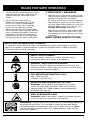
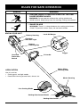
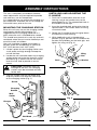
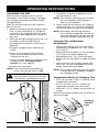
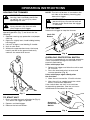
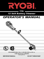
150r
12 Volt Battery Trimmer
OPERATOR’S MANUAL
FOR QUESTIONS, CALL 1-800-345-8746 in U.S. or
1-800-265-6778 in CANADA
www.ryobi.com
IMPORTANT MANUAL
DO NOT THROW AWAY
INTRODUCTION
THANK YOU
Thank you for buying this quality product. This
modern outdoor power tool will provide many
hours of useful service. You will find it to be a
great labor-saving device. This operator’s
manual provides you with easy-to-understand
operating instructions. Read the whole manual
and follow all the instructions to keep your new
outdoor power tool in top operating condition.
The other manual that came with your power
tool, the parts manual, contains all the
information that you need to order parts.
PRODUCT REFERENCES,
ILLUSTRATIONS AND
SPECIFICATIONS
All information, illustrations and specifications
in this manual are based on the latest product
information available at the time of printing. We
reserve the right to make changes at any time
without notice.
Copyright© 1998 Ryobi Outdoor Products, Inc.
All Rights Reserved.
Bump Head™ is a trademark of Ryobi Outdoor
Products.
SERVICE INFORMATION
Service on this unit both within and after the
warranty period should be performed only by
an authorized and approved service dealer.
Dial:
1-800-345-8746 in the United States or
1-800-265-6778 in Canada
to obtain the listing of the authorized service
dealer nearest you.
DO NOT RETURN THE UNIT TO THE
RETAILER.
NOTE: PROOF OF PURCHASE WILL BE
REQUIRED FOR WARRANTY
SERVICE.
Make sure this manual is carefully read and
understood before starting or operating this
equipment.
THIS PRODUCT IS COVERED BY ONE OR
MORE US PATENTS.
OTHER PATENTS PENDING.
2
TABLE OF CONTENTS
I.
Rules for Safe Operation . . . . . . . . . . . 3-6
A. Important Safety Information . . . . . . .3-4
B. Safety and International Symbols . . .5-6
C. Know Your Unit . . . . . . . . . . . . . . . . . .6
II.
Assembly Instructions . . . . . . . . . . . . . . . 7
A. Mounting the Charging Station . . . . . . 7
B. Installing and Adjusting D-Handle . . . 7
III. Operating Instructions . . . . . . . . . . . . 8-10
A. Charging the Unit . . . . . . . . . . . . . . . . .8
B. Holding the Trimmer . . . . . . . . . . . . . . .9
C. To Start Unit . . . . . . . . . . . . . . . . . . . . .9
D. To Stop Unit . . . . . . . . . . . . . . . . . . . . .9
E. Overload Protection Switch . . . . . . . . .9
F. Adjusting Trimming Line Length . . . . .10
G. Tips for Best Trimming Results . . . . . .10
H. Decorative Trimming . . . . . . . . . . . . . .10
IV. Maintenance and Repair Instructions .11-15
A. General Recommendations . . . . . . . . 11
B. Line Installation . . . . . . . . . . . . . . 11-12
C. Installing a Prewound Reel . . . . . . . . . 13
D. Replacing the Charger . . . . . . . . . . . .13
E. Battery Pack Replacement . . . . . . 14-15
V.
Cleaning and Storage . . . . . . . . . . . . . . 16
A. Replacement parts . . . . . . . . . . . . . . 16
VI. Troubleshooting Chart . . . . . . . . . . . . . . 16
VII. Specifications . . . . . . . . . . . . . . . . . . . . 17
VIII. Warranty . . . . . . . . . . . . . . . . . . . . . . . . .18
CONTENTS OF CARTON
This unit should consist of the following:
• Model 150r, Assembled with D-Handle
and Cutting Attachment Shield
• Charging Station with Charger
• Operator's Manual
• Product Registration Card
RULES FOR SAFE OPERATION
The purpose of safety symbols is to attract your
attention to possible dangers. The safety
symbols, and their explanations, deserve your
careful attention and understanding. The safety
warnings do not by themselves eliminate any
danger. The instructions or warnings they give
are not substitutes for proper accident
prevention measures.
DANGER: Failure to obey a safety
SYMBOL
safety warning can result in injury to
yourself and others. Always follow
the safety precautions to reduce the
risk of fire, electric shock, and
personal injury.
MEANING
SAFETY ALERT SYMBOL:
Indicates danger, warning, or
caution. Attention is required in
order to avoid serious personal
injury. May be used in conjunction
with other symbols or pictographs.
NOTE: Advises you of information or
instructions vital to the operation or
maintenance of the equipment.
warning will result in serious injury
to yourself or to others. Always
follow the safety precautions to
reduce the risk of fire, electric
shock, and personal injury.
WARNING: Failure to obey a
CAUTION: Failure to obey a safety
warning may result in property
damage or personal injury to
yourself or to others. Always follow
the safety precautions to reduce the
risk of fire, electric shock, and
personal injury.
• IMPORTANT SAFETY INFORMATION •
READ ALL INSTRUCTIONS
WARNING: When using electric
trimmers, basic safety precautions
should always be followed to reduce
the risk of fire, electric shock, and
personal injury. Carefully read and
understand the entire Operator's
Manual before using your trimmer.
Pay close attention to the Operating
Instructions and Safety Warnings.
BEFORE OPERATING
• Read the instructions carefully. Be familiar
with the controls and proper use of the unit.
• Do not operate this unit when tired, ill, or
under the influence of alcohol, drugs, or
medication.
• Inspect the unit before use. Replace
damaged parts. Check for battery leaks.
Make sure all fasteners are in place and
secure. Replace cutting attachment parts
that are cracked, chipped, or damaged in
any way. Make sure the cutting attachment is
properly installed and securely fastened. Be
sure the cutting attachment shield is properly
attached, and positioned as recommended.
Failure to do so can result in personal injury
to the operator and bystanders, as well as
damage to the unit.
• Avoid dangerous environments. Never
operate your unit in damp or wet conditions.
Moisture is a shock hazard.
• Do not use the unit in the rain.
• Do not handle the unit with wet hands.
• Children and teens under the age of 15 must
not use the unit, except for teens guided by
an adult.
• Use only 0.080 in (2.03 mm) diameter
genuine Ryobi replacement line. Never use
metal-reinforced line, wire, or rope, etc..
These can break off and become a
dangerous projectile.
• Be aware of the risk of injury to the head,
hands and feet.
• Clear the area to be cut before each use.
Remove all objects such as rocks, broken
glass, nails, wire, or string which can be
thrown or become entangled in the cutting
attachment. Clear the area of children,
bystanders, and pets. At a minimum, keep
all children, bystanders and pets outside a
50 ft. (15m) radius; there still may be a risk
to bystanders from thrown objects.
Bystanders should be encouraged to wear
eye protection. If you are approached, stop
the motor and cutting attachment
immediately.
3
RULES FOR SAFE OPERATION
SAFETY WARNINGS FOR
BATTERY TRIMMERS
• Battery tools do not have to be plugged into
an electrical outlet; therefore, they are always
in operating condition. Be aware of possible
hazards, such as cutting attachment, even
when tool is not operating.
• Use only the charging stand provided with
your unit. Do not substitute any other
charging stand. Use of another charging
stand could promote batteries to explode
causing possible serious injury.
• Do not place battery units or their batteries
near fire or heat. They may explode causing
serious personal injury and damage to unit.
• Do not charge unit in a damp or wet location.
• Your unit should be charged in a location
where the temperature is more than 50˚F
(10˚C) but less than 100˚F (38˚C).
• Do not disassemble the battery housing.
Battery should be recycled, consult your
local waste authority for information
regarding available recycling and/or disposal
options.
SAFETY WARNINGS FOR
CHARGING STANDS
• Before using charging stand, read all
instructions and cautionary markings in this
manual, on charging stand, and product
using charging stand.
• Do not expose charger to rain or snow.
• To reduce risk of injury, charge only
sealed lead-acid rechargeable batteries.
Other types of batteries may burst, causing
personal injury and damage.
• To reduce risk of damage to charger body
and cord, pull by the charger body, rather
than cord, when disconnecting the charger.
• Make sure charger cord is located so that it
will not be stepped on, tripped over, or
otherwise subjected to damage or stress.
• Do not operate charger with a damaged
cord or plug. If damaged, replaced charger
immediately.
• Do not operate charger if it has received a
sharp blow, been dropped, or otherwise
damaged in any way. If the charger case is
damaged, replace the charger.
• Do not disassemble charger. The charger is
not serviceable; disassembly may result in a
risk of electric shock or fire.
• To reduce risk of electric shock, unplug the
charger from outlet before attempting any
maintenance or cleaning.
• Do not use charger outdoors.
4
WHILE OPERATING
• To avoid accidental starting, never carry your
trimmer with your finger on the trigger.
• Wear safety glasses or goggles that are
marked as meeting ANSI Z87.1-1989
standards, and ear/hearing protection when
operating this unit. Wear a face or dust mask
if the operation is dusty. Long sleeve shirts
are recommended.
• Wear heavy, long pants, boots and gloves.
Do not wear loose clothing, jewelry, short
pants, sandals or go barefoot. Secure hair
above shoulder level.
• The cutting attachment shield must always
be in place while operating the unit. Do not
operate unit without trimming line extended,
and the proper line installed. Do not extend
the trimming line beyond the length of the
shield.
• Adjust the handle to your size to provide the
best grip.
• Be sure the cutting attachment is not in
contact with anything before starting the unit.
• Use the unit only in daylight or good artificial
light.
• Use the right tool. Only use this tool for the
purpose intended.
• Do not overreach. Always keep proper
footing and balance.
• Do not force the unit. It will do the job better
and with less likelihood of a risk of injury at
the rate for which it was designed.
• Always hold the unit with both hands when
operating. Keep a firm grip on both the
battery housing grip and D- handle.
• Keep hands, face, and feet at a distance
from all moving parts. Do not touch or try to
stop the cutting attachment when it is
rotating.
• Always stop the motor when cutting is
delayed or when walking from one cutting
location to another.
• If you strike or become entangled with a
foreign object, stop the unit immediately and
check for damage. Do not operate before
repairing damage. Do not operate the unit
with loose or damaged parts.
• Release the trigger, ensure the lock-off
button resets and allow the motor to stop
for maintenance, repair, or for changing the
cutting attachment or other attachments.
• Keep unit clean of vegetation and other
materials. They may become lodged
between the cutting attachment and shield.
RULES FOR SAFE OPERATION
• Use only genuine Ryobi replacement parts
when servicing this unit. These parts are
available from your authorized service
dealer.
• Do not use parts, accessories or
attachments not authorized by Ryobi
for this unit. Doing so could lead to
serious injury to the user, or damage
to the unit, and void your warranty.
• Battery tools do not have to be plugged
into an electrical outlet; therefore, they are
always in operating condition. Take extra
precautions and care when performing
maintenance, service or for changing the
cutting attachment or other attachments.
OTHER SAFETY WARNINGS
• Store the unit in a locked up and dry or high
and dry place to prevent unauthorized use or
damage, out of the reach of children.
• Be sure to secure the unit while transporting.
• Never douse or squirt the unit with water or
any other liquid. Keep handles dry, clean and
free from debris. Clean after each use, see
Cleaning and Storage instructions.
• Keep these instructions. Refer to them often
and use them to instruct other users. If you
loan someone this unit, also loan them these
instructions.
SAVE THESE INSTRUCTIONS
SAFETY AND INTERNATIONAL SYMBOLS
This operator's manual describes safety and international symbols and pictographs that may
appear on this product. Read the operator's manual for complete safety, assembly, operating
and maintenance and repair information.
SYMBOL
MEANING
• SAFETY ALERT SYMBOL
Indicates danger, warning, or caution. May be used in
conjunction with other symbols or pictographs.
• WARNING - READ OPERATOR'S MANUAL
Read the Operator’s Manual(s) and follow all warnings and
safety instructions. Failure to do so can result in serious injury
to the operator and/or bystanders.
• FOR SERVICE INFORMATION, CALL:
USA: 1-800-345-8746
CANADA: 1-800-265-6778
• WEAR EYE AND HEARING PROTECTION
WARNING: Thrown objects and loud noise can cause
severe eye injury and hearing loss. Wear eye protection
meeting ANSI Z87.1-1989 standards and ear protection
when operating this unit.
• KEEP BYSTANDERS AWAY
WARNING: Keep all bystanders, especially children and pets,
at least 50 feet (15 m) from the trimming area.
WARNING: The operation of any power tool can cause foreign objects to
be thrown into your eyes. This can lead to severe eye damage. Before
commencing power tool operation, always wear safety glasses or goggles
that are marked as meeting ANSI Z87.1-1989 standards, and a full face
shield when needed.
5
RULES FOR SAFE OPERATION
SYMBOL
MEANING
• THROWN OBJECTS AND ROTATING CUTTER CAN
CAUSE SEVERE INJURY
WARNING: Do not operate without the cutting attachment
shield in place. Keep away from the rotating cutting attachment.
• SHARP BLADE
WARNING: There is a sharp blade on the cutting attachment
shield. To prevent serious injury, do not touch blade.
KNOW YOUR UNIT
Lock-Off Button
Battery Housing
Charging
Indicator Light
Battery
Housing Grip
Trigger
Overload
Protection
Switch
D-handle
Motor Wires
Housing Tube
APPLICATION
Use this unit for;
• Cutting grass and light weeds.
• Decorative trimming around trees, fences, etc.
Motor Housing
Line Cutting Blade
Cutting Attachment Shield
Cutting Attachment
6
ASSEMBLY INSTRUCTIONS
This unit is completely assembled. However,
some adjustments may be required to provide
safe and easy use for the operator.
It is suggested that you mount the charging unit
per instructions and allow the unit to charge for
at least 36 hours prior to first use.
MOUNTING THE CHARGING STATION
Since this unit may stay on the charging station
continuously without overcharging, it is
suggested that the charging station be in a
place where the unit is intended to be stored.
This should be a place that is cool, dry and well
ventilated, where the unit can be locked-up and
out of the reach of children.
Your unit should be charged and stored in a
location where the temperature is more than
50˚F (10˚C) but less than 100˚F (38˚C).
1. Locate a place for the charging station near
a wall outlet and high enough to keep the
unit off the floor.
2. Locate the wall stud and mount the charging
station to the wall using the three (3) screws
provided (Fig 1). Make sure that the screws
enter the wall stud to provide a secure
mount.
INSTALLING AND ADJUSTING THE
D-HANDLE
1. Push the D-handle down onto the shaft
housing so that the handle slants to the
powerhead (Fig. 2). The squared bolt hole in
the handle is to the right.
2. Insert the shoulder bolt and washer into the
squared hole in the handle. Screw the wing
nut onto the bolt.
3. Rotate the D-handle to place the grip above
the top of the shaft housing.
4. While holding the unit in the operating
position (Fig. 3), position the D-handle to the
location that provides you the best grip, and
tighten the wing nut (Fig. 4).
Wing
Nut
Bolt
CAUTION: To prevent injury or
Washer
Fig. 2
damage to the unit, the charging
station must be mounted securely
to the wall.
3. Plug the charger into the wall outlet and
wrap any excess wire onto the cord wrap
on the charging station (Fig. 1).
Screw
Charging
Station
Wall
Outlet
Fig. 3
Charger
Cord
Wrap
Grip
Wall Stud
Fig. 1
Fig. 4
7
OPERATING INSTRUCTIONS
CHARGING THE UNIT
Make sure the charging station is securely
fastened to a wall and the charger is plugged
into a working wall outlet. See Mounting the
Charging Station.
Allow the unit to charge for at least 36 hours
prior to first use.
1. Slide the unit down into the charging station
until it is firmly seated (Fig. 5). The barrel
connector in the charging station will insert
into the unit. See Replacing the Charger if it
does not.
2. When the red indicator light on the unit is on,
the battery is being charged (Fig. 6).
If the light fails to come on, check for the
following:
a. Charger is plugged into a working wall
outlet.
b. Unit is firmly seated into the charging
station and the barrel connector is fully
inserted into the unit.
c. Barrel connector properly installed into the
charging station. See Replacing the
Charger if it is not, page 13.
d. Power at the wall outlet.
NOTE: If the wall outlet is operated by a
switch, be sure the switch is ON.
WARNING: To prevent serious
personal injury, have the wall outlet
checked by a qualified electrician.
3. The battery should be charged for at least
24 hours between uses.
NOTE: The trimmer’s operating time and the
life of the battery will be shorten if
step 3 is not followed.
4. Always place the unit back on the charging
station after each use. The unit is designed
so that that battery cannot be overcharged.
NOTE: The battery will heat up while the
unit is being charged. Be sure the air
vents on the battery housing are kept
cleared for proper ventilation (Fig. 5).
Charging Tips for Maximum
Performance
• Store and charge the unit in an area where
temperatures are between 50˚ F (10˚ C) and
100˚ F (38˚ C).
• Storing the unit or batteries in an area above
100˚ F (38˚ C) will reduce battery life.
• Storage below 50˚ F (10˚ C) will not reduce
battery life, but may require a longer charging
time.
• Store the unit on the charging station when
not in use. The unit is designed so that the
battery cannot be overcharged.
NOTE: The charging indicator light will remain
lit when the unit is properly installed in
the charging station.
Temperature Effects on Charging Time
• 50˚ F (10˚ C) to 100˚ F (38˚ C) – Battery will be
charged within 24 hours.
• 40˚ F (4 ˚C) to 50˚ F (10˚ C) – Battery will
require up to 48 hours for a full charge.
• Below 40˚ F (4 ˚C) – Battery will not reach full
charge.
Unit run time will be reduced when the battery is
not fully charged.
Air
Vents
Charging
Indicator
Light
Fig. 5
8
Fig. 6
OPERATING INSTRUCTIONS
HOLDING THE TRIMMER
WARNING: Always wear eye,
hearing, foot and body protection
to reduce the risk of injury when
operating this unit.
WARNING: To prevent serious
injury, do not carry the unit with
your finger on the trigger.
Before operating the unit, stand in in the
operating position (Fig. 7) and check for the
following:
1. Operator wearing eye protection and proper
clothing.
2. Right arm slightly bent, hand holding battery
housing grip.
3. Left arm straight, hand holding D-handle.
4. Unit at waist level.
5. Without the operator bent over, the bump
head is parallel to the ground and easily
contacts the material to be cut.
NOTE: The lock-off button is located on the
left side of the battery housing grip,
above the trigger.
WARNING: To prevent serious
personal injury, ensure the lock-off
button resets each time the trigger
is released.
TO STOP UNIT
Release the trigger to stop the trimmer.
Lock-Off
Button
Fig. 8
OVERLOAD PROTECTION SWITCH
This unit is equipped with an overload protection
switch to prevent damage to the motor in the
event of overheating.
If the switch pops out:
1. Release the trigger and allow the unit to cool
for a minute.
2. Press the overload switch to reset and
resume operation (Fig. 9).
If the switch pops again shortly after
the first time:
1. Allow the unit to cool for 15 to 30 minutes.
2. After the unit has cooled, push the switch
back in and resume operation.
If the switch does not stay in or continues
to pop during operation, take the unit to an
authorized service dealer for repair.
Fig. 7
TO START UNIT
1. Press and hold the lock-off button in (Fig. 8).
This allows the trigger to operate.
2. Depress and hold trigger.
3. Release the lock-off button.
Overload
Protection
Switch
Fig. 9
9
OPERATING INSTRUCTIONS
TO ADJUST TRIMMING LINE LENGTH
Your trimmer is equipped with a bump head,
which allows the operator to release more
trimming line without stopping the motor. As
the line becomes frayed or worn, additional
line can be released by lightly tapping the
trimming head on the ground (Fig. 10) while
operating the trimmer.
NOTE: Always keep the trimming line fully
extended. Line release becomes
more difficult as cutting line
becomes shorter.
WARNING: Do not remove or alter
the line cutting blade assembly.
Excessive line length will cause the
motor to overheat and may result in
serious personal injury.
Each time the head is bumped, approximately
1 inch (25.4 mm) of trimming line is released.
A blade in the string guard will cut the line if
excess line is released.
For best results, tap the head on bare ground or
hard soil. If line release is attempted in tall grass,
the motor may overheat. Always keep the
trimming line fully extended. Line release
becomes more difficult as the cutting line
becomes shorter.
Fig. 10
DECORATIVE TRIMMING
Decorative trimming is accomplished by
removing all vegetation around trees, posts,
fences, etc. Use a 30-degree angle when
trimming with this method (Fig. 11).
Fig. 11
TIPS FOR BEST TRIMMING RESULTS
1. The correct angle for the cutting attachment
is parallel to the ground.
NOTE: Do not rest the bump head on
the ground.
2. DO NOT FORCE THE UNIT. Allow the very
tip of the line to do the cutting (especially
along walls). Cutting with more than the
tip will reduce cutting efficiency and may
overload the motor.
3. Grass over 200 mm (8 in.) should be cut by
working from top to the bottom in small
increments to avoid premature line wear or
motor drag.
4. Whenever possible, cut right to left. When
cutting to the left, the unit's cutting efficiency
is improved slightly. Also, the clippings are
thrown away from the operator.
5. Slowly move the trimmer into and out of the
area being cut, maintaining the trimmer at
the desired cutting height. This can be either
a forward-backward or side-to-side motion.
Cutting shorter lengths produces best
results.
6. Trim only when grass and weeds are dry.
7. The life of your cutting line is dependent
upon following the previous trimming
techniques, what is being cut, and where
the cutting is being done. For example, the
line will wear faster when trimming against
a foundation wall as opposed to trimming
around a tree. Some line breakage will
occur from:
• Entanglement with foreign matter.
• Normal line fatigue.
• Attempting to cut thick, stalky weeds.
• Forcing the line into objects such as walls or
fenceposts.
10
MAINTENANCE AND REPAIR INSTRUCTIONS
WARNING: Battery tools do not
Winding the Inner Reel with New Line
have to be plugged into an electrical
outlet; therefore, they are always in
operating condition. To prevent
serious personal injury, take extra
precautions and care when
performing maintenance, service or
for changing the cutting attachment
or other attachments.
To rewind the existing reel you must:
1. Check for the correct line size.
2. Remove the existing reel and spring.
3. Wind the existing reel with the new line.
4. Reinstall the existing reel and spring.
GENERAL RECOMMENDATIONS
The warranty on this line trimmer does not cover
items that have been subjected to operator
abuse or negligence. To receive full value from
the warranty, the operator must maintain the line
trimmer as instructed in this operator’s manual.
The Correct Line to Use
It is very important to use the correct diameter
size line. This unit uses 2.03 mm (.080 in.)
diameter trimmer line. The motor may overheat
and fail if you use a larger diameter line.
WARNING: Always use genuine
Ryobi replacement line. Do not use
metal-reinforced line.
BEFORE EACH USE CHECK FOR
DAMAGED/WORN PARTS
Removing the Existing Reel and Spring
• Bump head — Replace bump head parts
that are bent, warped, cracked, or damaged
in any way.
1. Remove the bump head cover by pressing in
both bump head cover tabs visible on either
side of the bump head outer spool (Fig. 12).
AFTER EACH USE CLEAN UNIT
AND LABELS
NOTE: The spring will push the cover up
when the tabs release.
2. Remove the inner reel and spring (Fig. 12).
3. Use a clean cloth to clean the inner surface
of the outer spool (Fig. 12).
• Clean the unit using a damp cloth with a mild
detergent.
NOTE: Do not use any strong detergents on
the plastic housing or the handle. They
can be damaged by certain household
cleaners that contain aromatic oils
such as pine and lemon, and by
solvents such as kerosene.
• Wipe off the unit with a clean, dry, soft cloth.
• Keep air vents free from debris at all times.
NOTE: Always clean the inner reel, outer
spool, and shaft before reassembling
the bump head.
Bump Head
Cover
PRESS TABS
LINE INSTALLATION
Always use genuine replacement line. Using
larger line then the unit is designed for may
make the motor overheat or fail.
There are two methods to replace the trimming
line.
• Wind the inner reel with new line
Inner Reel
• Install a prewound inner reel
Spring
Outer Spool
Fig. 12
11
MAINTENANCE AND REPAIR INSTRUCTIONS
4. Check the indexing teeth on the inner
reel and outer spool for wear (Fig. 13).
If necessary, remove burrs or replace
the reel and spool.
Indexing Teeth
Fig. 15
Reinstalling the Reel and Spring
Fig. 13
Winding the Existing Reel
1. Take approximately 12 feet (3.6 m) of new
trimming line, insert one end of the line into
the hole in the inner reel (Fig. 14).
2. Wind the line, in even and tight layers,
onto the reel (Fig. 14). Wind the line in the
direction indicated on the inner reel.
NOTE: Failure to wind the line in the direction
indicated will cause the bump head to
operate incorrectly.
3. Insert the end of the line into one of the two
holding slots (Fig. 15).
1. Insert the end of the line through the eyelet in
the outer spool (Fig. 16)
2. Place inner reel and spring inside the
outer spool.
NOTE: The spring must be assembled on
the inner reel before reassembling
the bump head.
3. Hold the inner reel in place, grasp the line
end and pull firmly to release the line from
the holding slot in the inner reel (Fig. 17).
4. Install the bump head cover over the inner
reel. Align the tabs on the cover with the
slots in the outer spool and press the cover
evenly down until it snaps into place .
NOTE: Make sure the bump head cover tabs
snap into place or the inner reel will
come out during operation.
Inner Reel Hole
Fig. 16
Fig. 14
12
MAINTENANCE AND REPAIR INSTRUCTIONS
REPLACING THE CHARGER
Use the following if the charger, barrel connector
or cord becomes damage, or if the barrel
connector is not connecting to the unit properly.
CAUTION: Only use the type of
charger specified for this unit. Any
other type may cause damage to the
unit, batteries and possible injury.
Fig. 17
INSTALLING A PREWOUND REEL
Always use genuine replacement line. Using
larger line then the unit is designed for may
make the motor overheat or fail.
1. Remove the bump head cover by pressing in
both bump head cover tabs visible on either
side of the bump head outer spool
(Fig. 12, Pg. 11).
NOTE: The spring will push the cover up
when the tabs release.
2. Remove the old inner reel and spring from
the outer spool (Fig. 12, Pg. 11).
3. Remove the spring from the old inner reel
(Fig. 12, Pg. 11).
4. Use a clean cloth to clean the inner surface
of the outer spool (Fig. 12, Pg. 11).
5. Insert the end of the line, on the prewound
reel, through the eyelet in the outer spool
(Fig. 16)
6. Place inner reel and spring inside the
outer spool.
NOTE: The spring must be assembled on
the inner reel before reassembling
the bump head.
7. Hold the inner reel in place, grasp the line
end and pull firmly to release the line from
the holding slot in the inner reel (Fig. 17).
8. Install the bump head cover over the inner
reel. Align the tabs on the cover with the
slots in the outer spool and press the cover
evenly down until it snaps into place.
NOTE: Make sure the bump head cover tabs
snap into place or the inner reel will
come out during operation.
Your trimmer requires a Ryobi #180294 12V
charger and #180295 charging station.
The charging instructions in this manual refer
only to these parts.
1. Unplug the charger from the wall outlet and
remove the unit from the charging station.
2. Remove the screw from the clamp holding
the barrel connector in place using a
standard or T-20 Torx bit screwdriver
(Fig. 18).
3. Remove the barrel connector from the slot
and replace charger, if needed.
4. Install the barrel connector into the charging
station. Make sure the connector is secure
and inserted correctly into the slot (see inset
Fig. 18).
5. Reinstall the clamp and screw.
6. Plug the charger into the wall outlet. Refer to
Charging the Unit for charging instructions.
Barrel Connector
Clamp
Screw
Charger
Charging
Station
Fig. 18
13
MAINTENANCE AND REPAIR INSTRUCTIONS
BATTERY PACK REPLACEMENT
This requires some disassembly of the unit. If
you feel unsure or unqualified to perform this,
take the unit to an authorized service center.
NOTE: If the battery requires replacing, we
recommend that this be done by an
authorized service center.
If you choose to replace the battery, use the
following instructions.
To Remove the Battery Pack
Refer to fig. 19 on the following page.
1. Place the unit on a workbench with the
left side of the battery housing facing up.
Giving access to the 11 screws holding
the housings together.
2. Remove all 11 screws using a standard or
T-20 Torx bit screwdriver and remove the left
battery housing.
3. Remove the battery pack. Keep the battery
cushions, 5 pieces, for reinstalling the new
battery pack.
CAUTION: If the battery pack has
signs of leakage, do not touch.
To avoid injury, take the unit to an
authorized service center for repair.
4. Disconnect the terminals from the battery
pack.
Prepare the Battery Pack for
Recycling
WARNING: Upon removal, cover
the battery pack’s terminals with
heavy duty adhesive tape. Do not
attempt to destroy or disassemble
battery or remove any of its
components. Sealed lead-acid
batteries must be recycled or
disposed of properly. Never touch
both terminals with metal objects
and/or body parts as short circuit
may result. Keep away from
children. Failure to comply with
these warnings could result in fire
and/or serious personal injury.
To preserve natural resources,
please recycle or dispose of
properly. THIS PRODUCT
CONTAINS A SEALED LEAD-ACID
BATTERY AND MUST BE
DISPOSED OF PROPERLY. Local,
state, or federal laws may prohibit
disposal of sealed lead-acid
batteries in ordinary trash. Consult
your local waste authority for
information regarding available
recycling and/or disposal options.
To Install the Battery Pack
Refer to fig. 19 on the following page.
1. Locate the terminal posts on the battery
pack. Identify the positive (+) and negative (-)
terminals.
2. Connect the red wire to the positive (+)
terminal and the black wire to the negative (-)
terminal. Make sure they are fully inserted
onto the terminals.
3. Place two battery cushions on the outside
steps in the right battery housing and install
the battery pack.
4. Make sure that all wires a routed correctly
and the following parts are positioned
correctly in the right battery housing.
• Charger Connection
• Charging Indicator Light
• Trigger Switch
• Trigger
• Lock-Off Button
• Motor Wires Tube
5. Place one (1) battery cushion into the right
battery housing center step, at the bottom
of the battery pack.
6. Place two battery cushions on the outside
steps in the left battery housing and install
the left battery housing.
NOTE: Make sure that the Lock-Off button is
fitting into the hole on the left battery
housing and that no wires will be
pinched when fitting the housings.
WARNING: To prevent serious
personal injury, ensure the lock-off
button resets each time the trigger
is released.
7. Reinstall and tighten the 11 screws using a
standard or T-20 Torx bit screwdriver.
NOTE: Take care not to over-tighten the
screws and stripping the housing.
Doing so will require replacement of
the damaged housing.
14
MAINTENANCE AND REPAIR INSTRUCTIONS
Left Battery
Housing
Housing
Screws (11)
Battery
Cushions (5)
Red Wire
(Positive +)
Charging
Indicator
Light
Black Wires
(Negative -)
Overload
Protection
Switch
Battery
Pack
Lock-Off
Button
Trigger
Steps
Trigger Switch
Motor Wires
Right
Battery
Housing
Motor Wires
Housing Tube
Charger
Connection
Fig. 19
15
CLEANING AND STORAGE
CLEANING THE UNIT
STORING THE UNIT
WARNING: Battery tools do not
have to be plugged into an electrical
outlet; therefore, they are always in
operating condition. To prevent
serious personal injury, take extra
precautions and care when
performing maintenance, cleaning
or servicing the unit.
• Do not use any strong detergents on the
plastic housing or the handle. They can
be damaged by certain aromatic oils such
as pine and lemon, and by solvents such
as kerosene. Moisture can also cause a
shock hazard. Wipe off any moisture with
a soft dry cloth.
• Use a small brush or the air discharge of a
small vacuum cleaner brush to clean the air
vents on the battery housing and motor
housing.
• Keep the air vents free of obstructions.
Clean the unit thoroughly before storing it. Hang
the unit on the charging station. Store the unit in
a dry, well-ventilated area, locked-up or up high,
out of the reach of children.
REPLACEMENT PARTS
Cutting Attachment Shield . . . . . . . . . . . .
Replacement Line . . . . . . . . . . . . . . . . . .
Replacement Line Cartridge . . . . . . . . . . .
Inner Reel Spring . . . . . . . . . . . . . . . . . . .
Bump Head Cover . . . . . . . . . . . . . . . . . .
Charger . . . . . . . . . . . . . . . . . . . . . . . . . .
Charging Station. . . . . . . . . . . . . . . . . . . .
12 Volt Battery Pack . . . . . . . . . . . . . . . . .
180293
610375
182155
180374
180376
180294
180295
180624
TROUBLESHOOTING
PROBLEM
Motor operates slowly or
will not operate
Battery will not charge
Cutting head will not
advance line
CAUSE
ACTION
Battery is not charged
Charge battery. See Charging the
Unit, page 8.
Overload protection switch
has popped
Reset overload protection switch
No power to charger or battery Check charger and charging
station. See Charging the Unit,
page 8.
Battery has failed
Replace Battery. See Battery Pack
Replacement, page 14.
Cutting head bound with grass
Stop the unit and clean cutting
attachment
Cutting head out of line
Refill with new line
Inner reel bound up
Replace the inner reel
Cutting head dirty
Clean inner reel and outer spool
Line welded
Disassemble, remove the welded
section and rewind the line
Line twisted when refilled
Disassemble and rewind the line
Not enough line is exposed
Push the Bump Knob and pull out
line until 4 in. (102 mm.) of line is
outside of the cutting attachment
If further assistance is required, contact your local authorized service dealer.
16
SPECIFICATIONS
BATTERY, MOTOR & CUTTING ATTACHMENT
Motor . . . . . . . . . . . . . . . . . . . . . . . . . . . . . . . . . . . . . . . . . . . . . . . . . . . . . . . . . 12 Volt DC, 15 Amps
Battery . . . . . . . . . . . . . . . . . . . . . . . . . . . . . . . . . . . . . . . . . . . . . . . . . . . . . Sealed Lead-Acid, 12 Volt
Motor Wire Housing Tube . . . . . . . . . . . . . . . . . . . . . . . . . . . . . . . . . . . . . . . . . . . . . . . Aluminum Tube
Unit Weight (With cutting attachment, cutting attachment shield and D-handle) . . . . . 10.2 lbs. (3.8 kg.)
Cutting Mechanism . . . . . . . . . . . . . . . . . . . . . . . . . . . . . . . . . . . . . . . . . . . . . . . . . . . . . .Bump Head
Line Spool Diameter . . . . . . . . . . . . . . . . . . . . . . . . . . . . . . . . . . . . . . . . . . . . . . . . . . . 3 in (76.2 mm)
Trimming Line Diameter . . . . . . . . . . . . . . . . . . . . . . . . . . . . . . . . . . . . . . . . . . . . . 0.080 in (2.03 mm.)
Cutting Path Diameter . . . . . . . . . . . . . . . . . . . . . . . . . . . . . . . . . . . . . . . . . . . . . . . . . 10 in. (254 mm)
17
LIMITED TWO-YEAR WARRANTY
RYOBI OUTDOOR PRODUCTS warrants each new
RYOBI Product for two (2) years according to the
following terms.
This warranty extends to the original retail purchaser
only and commences on the date of original retail
purchase.
Any part of the RYOBI Product manufactured or
supplied by RYOBI and found in the reasonable
judgement of RYOBI to be defective in material or
workmanship will be repaired or replaced by an
authorized RYOBI service dealer without charge
for parts and labor.
The RYOBI Product including any defective part
must be returned to an authorized service dealer
within the warranty period. The expense of delivering
the RYOBI Product to the dealer for warranty work
and the expense of returning it back to the owner
after repair or replacement will be paid for by the
owner. RYOBI’s responsibility in respect to claims is
limited to making the required repairs or replacements
and no claim of breach of warranty shall be cause
for cancellation or rescission of the contract of sale
of any RYOBI Product. Proof of purchase will be
required by the dealer to substantiate any warranty
claim. All warranty work must be performed by an
authorized RYOBI service dealer.
This warranty is limited to ninety (90) days from
the date of original retail purchase for any RYOBI
Product that is used for rental or commercial
purposes, or any other income-producing purpose.
This warranty does not cover any RYOBI Product
that has been subject to misuse, neglect, negligence,
or accident, or that has been operated in any way
contrary to the operating instructions as specified in
the RYOBI Operator’s Manual. This warranty does not
apply to any damage to the RYOBI Product that is the
result of improper maintenance or to any RYOBI
Product that has been altered or modified so as to
adversely affect the product's operation, performance
or durability or that has been altered or modified so
as to change its intended use. The warranty does not
extend to repairs made necessary by normal wear or
by the use of parts or accessories which are either
incompatible with the RYOBI Product or adversely
affect its operation, performance or durability.
ALL IMPLIED WARRANTIES ARE LIMITED IN
DURATION TO THE TWO (2) YEAR WARRANTY
PERIOD OR NINETY (90) DAYS FOR PRODUCTS
USED FOR ANY COMMERCIAL PURPOSE.
ACCORDINGLY, ANY SUCH IMPLIED
WARRANTIES INCLUDING MERCHANTABILITY,
FITNESS FOR A PARTICULAR PURPOSE, OR
OTHERWISE, ARE DISCLAIMED IN THEIR
ENTIRETY AFTER THE EXPIRATION OF THE
APPROPRIATE TWO-YEAR OR NINETY DAY
WARRANTY PERIOD. RYOBI’S OBLIGATION
UNDER THIS WARRANTY, IS STRICTLY AND
EXCLUSIVELY LIMITED TO THE REPAIR OR
REPLACEMENT OF DEFECTIVE PARTS, AND
ROP DOES NOT ASSUME OR AUTHORIZE
ANYONE TO ASSUME FOR THEM ANY OTHER
OBLIGATION. SOME STATES DO NOT ALLOW
LIMITATIONS ON HOW LONG AN IMPLIED
WARRANTY LASTS, SO THE ABOVE LIMITATION
MAY NOT APPLY TO YOU.
RYOBI ASSUMES NO RESPONSIBILITY FOR
INCIDENTAL, CONSEQUENTIAL OR OTHER
DAMAGES INCLUDING, BUT NOT LIMITED
TO EXPENSE OF RETURNING THE RYOBI
PRODUCT TO AN AUTHORIZED SERVICE
DEALER AND EXPENSE OF DELIVERING IT BACK
TO THE OWNER, MECHANIC’S TRAVEL TIME,
TELEPHONE OR TELEGRAM CHARGES, RENTAL
OF A LIKE PRODUCT DURING THE TIME
WARRANTY SERVICE IS BEING PERFORMED,
TRAVEL, LOSS OR DAMAGE TO PERSONAL
PROPERTY, LOSS OF REVENUE, LOSS OF USE
OF THE PRODUCT, LOSS OF TIME, OR
INCONVENIENCE. SOME STATES DO NOT
ALLOW THE EXCLUSION OR LIMITATION OF
INCIDENTAL OR CONSEQUENTIAL DAMAGES,
SO THE ABOVE LIMITATION OR EXCLUSION
MAY NOT APPLY TO YOU.
This warranty gives you specific legal rights, and
you may also have other rights which vary from
state to state.
This warranty applies to all RYOBI Products
manufactured by RYOBI and sold in the United
States and Canada.
To locate your nearest service dealer dial
1-800-345-8746 in the United States or
1-800-265-6778 in Canada.
In addition, this warranty does not cover:
A. Wear items - Bump Knobs, Outer Spools,
Cutting Line, Inner Reels.
RYOBI reserves the right to change or improve the
design of any RYOBI Product without assuming any
obligation to modify any product previously
manufactured.
RYOBI OUTDOOR PRODUCTS
550 N. 54th Street
Chandler, AZ 85226 U.S.A.
RYOBI CANADA INC.
275 Industrial Rd
Cambridge, Ontario N1R 6K2 CANADA
SAVE THESE INSTRUCTIONS FOR FUTURE REFERENCE.
FOR QUESTIONS CALL 1-800-345-8746 IN U.S.
OR 1-800-265-6778 IN CANADA
OPERATOR’S MANUAL PART NO. 182154
PRINTED IN U.S.A.
REV. A (51522)
10/98