1
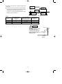
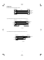
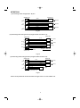
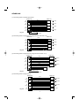
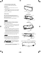
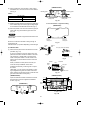
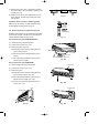
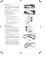
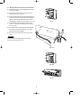
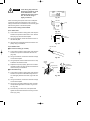
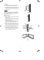
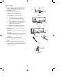
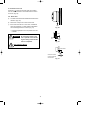
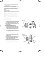
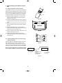
INSTALLATION INSTRUCTIONS
- Split system air conditioner COOL / DRY/ HEAT Model
This air conditioner uses the new refrigerant R410A.
Contents
Model Combinations
Page
IMPORTANT!
Please Read Before Starting .................................. 1
1.
GENERAL .......................................................... 2
1-1. Tools Required for Installation (not supplied)
1-2. Accessories Supplied with Unit
1-3. Optional Copper Tubing Kit
1-4. Type of Copper Tube and Insulation Material
1-5. Additional Materials Required for Installation
2.
INSTALLATION SITE SELECTION ................... 3
2-1. Indoor Unit
2-2. Embedding the Tubing and Wiring
3.
HOW TO INSTALL THE INDOOR UNIT ............ 9
3-1. Remove the Rear Panel from the Unit
3-2. Make a Hole
3-3. Install the Rear Panel on the Wall
3-4. Remove the Grille to Install the Indoor Unit
3-5. Shape the Indoor Side Tubing
3-6. Wiring Instructions
3-7. Wiring Instructions for Inter-unit Connections
3-8. Mounting
3-9. Drain Hose
4.
HOW TO SECURE THE WIRELESS REMOTE
CONTROL UNIT................................................ 18
4-1. Mounting on a Wall
5.
ADDRESS SETTING OF THE REMOTE
CONTROL UNIT................................................ 19
5-1. Setting the Remote Controller Address
5-2. Operating Multiple Indoor Units with a Single
Remote Controller
6.
TEST RUN......................................................... 20
7.
INSTALLATION CHECK SHEET ...................... 20
85264189902000
02/2004
Combine indoor and outdoor units only as listed
below.
Indoor Unit
Outdoor Unit
AWMI28AHL
AE2MI56AH
AWMI36AHL
AE3MI70AH
AWMI50AHL
AE4MI91AH
AWMI70AHL
Power Source:
50 Hz, single-phase, 220 – 240 V / 60 Hz,
single-phase 220 V
Combinations of indoor and outdoor units
Connect indoor and outdoor units only in the combinations listed in the catalog or installation manual.
CAUTION
Connecting any other model may result in
operation failure and system damage.
IMPORTANT!
Please Read Before Starting
When Installing…
This air conditioning system meets strict safety and operating standards. As the installer or service person, it is an
important part of your job to install or service the system
so it operates safely and efficiently.
…In a Ceiling or Wall
Make sure the ceiling/wall is strong enough to hold the
unit’s weight. It may be necessary to construct a strong
wood or metal frame to provide added support.
For safe installation and trouble-free operation, you
must:
● Carefully read this instruction booklet before beginning.
● Follow each installation or repair step exactly as shown.
● Observe all local, state, and national electrical codes.
● Pay close attention to all warning and caution notices
given in this manual.
This symbol refers to a hazard
or unsafe practice which can
WARNING
result in severe personal injury
or death.
This symbol refers to a hazard
or unsafe practice which can
CAUTION
result in personal injury or
product or property damage.
…In a Room
Properly insulate any tubing run inside a room to prevent
“sweating” that can cause dripping and water damage to
walls and floors.
When Connecting Refrigerant Tubing
• Do not add any refrigerant, air, or substance into the
refrigeration circuit other than the designated refrigerant (R410A). Adding anything other than the specified
refrigerant may cause the pressure to rise excessively
in the refrigeration circuit, rupturing the circuit and
causing injury or damage.
• Use all-new tubing and flare nuts to make the tubing
connections. Using any previous parts (from R22based systems) may result in damage to the equipment, and may lead to the refrigeration circuit rupturing, causing a serious accident.
If Necessary, Get Help
These instructions are all you need for most installation
sites and maintenance conditions. If you require help for
a special problem, contact our sales/service outlet or
your certified dealer for additional instructions.
• Apply refrigerant lubricant to the matching surfaces of
the flare and union tubes before connecting them,
then tighten the nut with a torque wrench for a leakfree connection.
In Case of Improper Installation
The manufacturer shall in no way be responsible for
improper installation or maintenance service, including
failure to follow the instructions in this document.
• Check carefully for leaks before starting the test run.
When Servicing
SPECIAL PRECAUTIONS
WARNING
• Turn the power OFF at the main power box (mains)
before opening the unit to check or repair electrical
parts and wiring.
When Wiring
• Keep your fingers and clothing away from any moving
parts.
ELECTRICAL SHOCK CAN CAUSE
SEVERE PERSONAL INJURY OR DEATH.
ONLY A QUALIFIED, EXPERIENCED
ELECTRICIAN SHOULD ATTEMPT TO
WIRE THIS SYSTEM.
• Clean up the site after you finish, remembering to
check that no metal scraps or bits of wiring have been
left inside the unit being serviced.
• Do not supply power to the unit until all wiring and tubing are completed or reconnected and checked.
Others
• Highly dangerous electrical voltages are used in this
system. Carefully refer to the wiring diagram and
these instructions when wiring. Improper connections
and inadequate grounding can cause accidental
injury or death.
CAUTION
• Ventilate any enclosed areas when installing or testing the
refrigeration system. Escaped refrigerant gas, on contact
with fire or heat, can produce dangerously toxic gas.
• Ground the unit following local electrical codes.
• Connect all wiring tightly. Loose wiring may cause overheating at connection points and a possible fire hazard.
• Confirm upon completing installation that no refrigerant
gas is leaking. If escaped gas comes in contact with a
stove, gas water heater, electric room heater or other
heat source, it can produce dangerously toxic gas.
When Transporting
Be careful when picking up and moving the indoor and outdoor units. Get a partner to help, and bend your knees when
lifting to reduce strain on your back. Sharp edges or thin aluminum fins on the air conditioner can cut your fingers.
1
1. General
6.
7.
8.
9.
10.
11.
12.
13.
14.
15.
This booklet briefly outlines where and how to install
the air conditioning system. Please read over the entire
set of instructions for the indoor and outdoor units and
make sure all accessory parts listed are with the system before beginning.
1-1. Tools Required for Installation (not supplied)
1. Standard screwdriver
2. Phillips head screwdriver
3. Knife or wire stripper
4. Tape measure
5. Carpenter’s level
Sabre saw or key hole saw
Hacksaw
Core bits
Hammer
Drill
Tube cutter
Tube flaring tool
Torque wrench
Adjustable wrench
Reamer (for deburring)
1-2. Accessories Supplied with Unit
Table 1
Q’ty
Parts
Remote
control unit
1
Remote
control holder
AAA alkaline
battery
2
Parts
Figure
Tapping
screw
Figure
Trusshead
screw
Q’ty
Parts
1
Tapping
screw
3.
Copper tubing for connecting the outdoor unit to the
indoor unit is available in kits which contain the narrow
and wide tubing, fittings and insulation. Consult your
nearest sales outlet or A/C workshop.
CAUTION
If you wish to purchase these materials separately from
a local source, you will need:
Deoxidized annealed copper tube for refrigerant
tubing as detailed in Table 2.
Cut each tube to the appropriate lengths +30 cm to
40 cm to dampen vibration between units.
Table 2
Narrow Tube
Model
Wide Tube
Outer Dia.
Thickness
Outer Dia.
Thickness
AWMI28AHL
6.35 mm
0.8 mm
9.52 mm
0.8 mm
AWMI36AHL
6.35 mm
0.8 mm
9.52 mm
0.8 mm
AWMI50AHL
6.35 mm
0.8 mm
9.52 mm
0.8 mm
AWMI70AHL
6.35 mm
0.8 mm
12.7 mm
0.8 mm
2.
Foamed polyethylene insulation for the specified
copper tubes as required to precise length of tubing. Wall thickness of the insulation should be not
less than 8 mm.
2
4 × 30 mm
8
Use insulated copper wire for field wiring. Wire size
varies with the total length of wiring. Refer to 3-6.
Wiring Instructions for details.
1-4. Type of Copper Tube and Insulation Material
1.
Trusshead
screw
Q’ty
2
4 × 16 mm
1-3. Optional Copper Tubing Kit
Figure
Check local electrical codes
and regulations before
obtaining wire. Also, check
any specified instructions or
limitations.
1-5. Additional Materials Required for Installation
1.
2.
Refrigeration (armored) tape
Insulated staples or clamps for connecting wire
(See local codes)
Putty
Refrigeration lubricant
Clamps or saddles to secure refrigerant tubing
3.
4.
5.
2. Installation Site Selection
2-1. Indoor Unit
WARNING
To prevent abnormal heat generation and the possibility of
fire, do not place obstacles,
enclosures, and grilles in front
of or surrounding the air conditioner in a way that may
block air flow.
AVOID:
●
direct sunlight.
●
nearby heat sources that may affect performance of
the unit.
●
areas where leakage of flammable gas may be
expected.
●
placing or allowing any obstructions near the A/C
inlet or outlet.
●
installing in rooms that contain instant-on (rapidstart) fluorescent lamps. (These may prevent the A/C
from receiving signals.)
●
places where large amounts of oil mist exist.
●
installing in locations where there are devices that
generate high-frequency emissions.
Indoor unit
Drain hose
DO:
●
select an appropriate position from which every corner of the room can be uniformly cooled. (High on a
wall is best.)
●
select a location that will hold the weight of the unit.
●
select a location where tubing and drain hose have
the shortest run to the outside. (Fig. 1)
●
allow room for operation and maintenance as well as
unrestricted air flow around the unit. (Fig. 2)
●
install the inter-unit cable more than 1 meter away
from any antenna or power lines or connecting wires
used for television, radio, telephone, security system, or intercom. Electrical noise from any of these
sources may affect operation.
Outside drainage
Fig. 1
15 cm
min.
15 cm min.
Front View
Fig. 2
3
15 cm
min.
●
●
install in a sturdy manner to avoid increased operating noise.
Tubing length (L1)
INDOOR
UNIT (1)
install the unit within the maximum elevation difference (H1, H2, H3, H4) above or below the outdoor
unit and within a total tubing length (L1+L2,
L1+L2+L3, L1+L2+L3+L4) from the outdoor unit as
detailed in Table 3 and Fig. 3a.
INDOOR
UNIT (2)
Elevation
difference (H1)
L2
OUTDOOR
UNIT
H2
L3
H4
INDOOR
UNIT (4)
INDOOR
UNIT (3)
L4
H3
Fig. 3a
Table 3
Model
(Outdoor unit)
Max. Allowable Tubing
Length per unit
(m)
Limit of Total Tubing
Length (L1+L2), (L1+L2+L3)
or (L1+L2+L3+L4) (m)
Limit of Elevation
Difference (H)
(m)
AE2MI56AH
25
35 (L1+L2)
10
AE3MI70AH
25
50 (L1+L2+L3)
10
AE4MI91AH
30
70 (L1+L2+L3+L4)
10
CAUTION
Indoor unit
For stable operation of the
air conditioner, do not
install wall-mounted type
indoor units less than 1.5 m
from floor level.
Minimum height
from floor level
1.5 m
Floor level
Fig. 3b
4
Wall
AE2MI56AH
(1) Connecting indoor unit types (28 – 36) at B
Outdoor unit
Indoor unit
φ6.35
(28 36 type)
A
φ9.52
φ6.35
(28 36 type)
B
φ9.52
Fig. 2a
(2) Connecting indoor unit type 50 at B (Length of tube: more than 17 m)
Outdoor unit
Indoor unit
φ6.35
(28 36 types)
A
φ9.52
φ9.52
φ6.35
(50 type)
B
φ12.7
φ9.52
Flare φ9.52 Union φ12.7 (More than 17 m)
Union φ12.7 Flare φ9.52
A joint for connecting tubes of
different sizes
Fig. 2b
(3) Connecting indoor unit type 50 at B (Length of tube: less than 17 m)
Outdoor unit
φ6.35
(28 36 types)
A
φ9.52
φ9.52
φ6.35
(50 type)
B
φ9.52
Indoor unit
φ9.52
(Less than 17 m)
Fig. 2c
5
AE3MI70AH
(1) Connecting indoor unit types (28 – 36) at C
Outdoor unit
Indoor unit
φ6.35
(28 36 type)
A
φ9.52
φ9.52
φ6.35
(28 36 type)
B
φ9.52
φ9.52
φ6.35
(28 36 type)
C
φ9.52
φ9.52
Fig. 2d
(2) Connecting indoor unit type 50 at C (Length of tube: more than 17 m)
Indoor unit
Outdoor unit
φ6.35
(28 36 types)
A
φ6.35
φ9.52
φ9.52
(28 36 types)
B
φ9.52
φ9.52
φ6.35
(50 type)
C
φ12.7
φ9.52
Flare φ9.52 Union φ12.7 (More than 17 m)
Union φ12.7 Flare φ9.52
A joint for connecting tubes of
different sizes
Fig. 2e
(3) Connecting indoor unit type 50 at C (Length of tube: less than 17 m)
Outdoor unit
Indoor unit
φ6.35
A
(28 36 types)
φ9.52
φ9.52
B
φ9.52
(28 36 types)
φ9.52
φ6.35
C
φ9.52
φ6.35
(50 type)
φ9.52
(Less than 17 m)
Fig. 2f
Note: It is not possible to connect the indoor unit type 70 to 2 or 3 room outdoor unit.
6
AE4MI91AH
(1) Connecting indoor unit types 28 to 36 at D
Outdoor unit
Indoor unit
φ6.35
A
(28 36 types)
φ9.52
φ9.52
φ6.35
φ6.35
φ9.52
(28 36 types)
B
φ9.52
(28 36 types)
C
φ9.52
φ9.52
φ6.35
(28 36 types)
D
φ12.7
φ9.52
Flare φ12.7 Union φ9.52
Fig. 2a
(φ12.7 → φ9.52) Supplied Reducer
(2) Connecting indoor unit type 50 at D (Length of tube: more than 17 m)
Outdoor unit
Indoor unit
φ6.35
(28 36 types)
A
φ9.52
φ9.52
φ6.35
(28 36 types)
B
φ9.52
φ9.52
φ6.35
(28 36 types)
C
φ9.52
φ9.52
φ6.35
(50 type)
D
φ12.7
φ12.7
(More than 17 m)
Fig. 2b
Union φ12.7
Flare φ9.52
(3) Connecting indoor unit type 50 at D (Length of tube: less than 17 m)
Outdoor unit
Indoor unit
φ6.35
(28 36 types)
A
φ9.52
φ9.52
φ6.35
(28 36 types)
B
φ9.52
φ9.52
φ6.35
(28 36 types)
C
φ9.52
φ9.52
φ6.35
(50 type)
D
φ12.7
φ9.52
Flare φ12.7
Fig. 2c
Union φ9.52
(φ12.7 → φ9.52) Supplied Reducer
(4) Connecting indoor unit type 70 at D
Outdoor unit
(28 36 types)
A
φ9.52
φ9.52
Fig. 2d
D
φ12.7
φ6.35
(28 36 types)
B
φ9.52
C
φ9.52
Indoor unit
φ6.35
φ6.35
φ9.52
(28 36 types)
φ9.52
φ6.35
(70 type)
φ12.7
7
2-2. Embedding the Tubing and Wiring
●
Before beginning embedding installation work, consult fully with agencies or offices related to the building’s foundation, construction, electricity, and water.
●
Wait to make connections to the embedded portion.
Each connection step is described later in this
manual.
●
Securely cover the end of the embedded tubing to
prevent intrusion of dirt or moisture.
●
If an embedded tube is to be left for a long time, fill
the tube with nitrogen and seal both ends securely.
If a tube is left open for an extended time, moisture
in the air inside the tubing may condense into water
droplets, and lead to water contamination of the
refrigerant circuit.
●
In order to prevent insulation breakdown and ground
faults, do not allow wiring ends to come in contact with
rainwater, or be subjected to condensation or dew.
●
Apply sufficient thermal insulation to the refrigerant
tubing and drain pipes.
8
3. How to Install the Indoor Unit
(AWMI28AHL)
3-1. Remove the Rear Panel from the Unit
(AWMI28AHL)
(1) Remove and discard the set screw on the rear
panel. (Fig. 5a)
(2) Press the 2 ▲ marks on the frame cover and disengage the stationary tabs from the frame. (Fig. 6a)
Set screw only for transportation
(3) Remove the rear panel.
Fig. 5a
(AWMI36/50AHL)
(AWMI36/50AHL)
First, remove the rear panel from the indoor unit.
Remove the screws attaching the panel and push up
the attachment tabs to permit a slight space, then completely remove the panel.
(The removed screws are no longer needed.)
Rear panel
Screw
Attachment tab
NOTE
Fig. 5b
Tubing can be extended in 5 directions as shown in
Fig. 6a. Select the direction you need providing the
shortest run to the outside unit.
●
(AWMI28AHL)
Rear panel
When left tubing is to be done, switch the drain hose
and drain cap. (For details, refer to “Switching drain
hose and drain cap” on page 13.)
3-2. Make a Hole
(1) Place the rear panel from the indoor unit on the wall
at the location selected. Make sure the panel is horizontal, using a carpenter’s level or tape measure to
measure down from the ceiling. Wait until after cutting
the hole before attaching the rear panel to the wall.
▲ marks
Fig. 6a
(2) Determine which side of the unit you should make
the hole for tubing and wiring. (Figs. 7a & b)
Right-rear
tubing
(recommended)
Left
tubing
NOTE
In the case of left-rear tubing, use the outside ▼ mark
for precise placement of the hose outlet. (Figs. 7a & b)
Left-rear
tubing
Right tubing
(3) Before making the hole, check carefully that no studs
or pipes are directly run behind the spot to be cut.
Downward tubing
Fig. 6b
CAUTION
Also avoid areas where electrical wiring or conduits are
located.
In case of left-rear, right-rear tubing (AWMI28AHL)
The above precautions are also applicable if tubing
goes through the wall in any other location.
Fig. 7a
9
(4) Using a sabre saw, key hole saw or hole-cutting
drill attachment, cut a hole in the wall. See Table 4
and Fig. 8.
(AWMI36/50AHL)
Bending point
Bending point
Table 4
Hole Dia. (mm)
AWMI28/36/50AHL
AWMI70AHL
65
80
Center of left-rear
tubing hole
Center of right-rear
tubing hole
Fig. 7b
(5) Measure the thickness of the wall from the inside edge
to the outside edge and cut PVC pipe at a slight angle
6 mm shorter than the thickness of the wall. (Fig. 9)
In case of left-rear or right-rear tubing
(AWMI70AHL)
(6) Place the plastic cover over the end of the pipe (for
indoor side only) and insert the pipe in the wall.
(Fig. 10)
NOTE
Hole should be made at a slight downward slant to the
outdoor side.
Center of
left-rear
tubing hole
3-3. Install the Rear Panel on the Wall
Be sure to confirm that the wall is strong enough to
suspend the unit.
See either Item a) or b) below depending on the wall type.
Center of
right-rear
tubing hole
Fig. 7c
Indoor
side
a) If Wooden Wall
Outdoor
side
PVC pipe (locally purchased)
(1) Attach the rear panel to the wall with the 6 screws
provided. (Fig. 11a)
If you are not able to line up the holes in the rear
panel with the beam locations marked on the wall,
use rawl plugs or toggle bolts to go through the
holes on the panel or drill 5 mm dia. holes in the
panel over the stud locations and then mount the
rear panel.
Fig. 8
Cut at slight angle
Fig. 9
INSIDE
When you attach the rear panel to the wall you
must use the top installation screw holes.
Install the panel levelly, confirming with a carpenter’s level.
(Alternately, you can check for levelness by hanging a weighted string from the center hole of the
panel, making sure the string lines up with the triangle mark at the bottom of the panel.)
OUTSIDE
Wall
Plastic
cover
PVC pipe
Slight
angle
Plastic cover
Fig. 10
(AWMI36/50AHL)
(AWMI36/50AHL)
805
Open the extension boards as marked and check
the dimensions. Use the supplied 8 installation
screws. (Fig.11b)
27.5
19.5
40
Hole for temporary attachment
285
Hole for tubing
(φ65 )
Fig. 11a
Fig. 11b
10
41
309
344
99
99
Extension
board
41
(AWMI28AHL)
450
27.5
(2) Double check with a ruler or carpenter’s level that
the panel is level. This is important to install the unit
properly. (Fig. 12)
(3) Make sure the panel is flush against the wall. Any
space between the wall and unit will cause noise
and vibration.
Fig. 12
b) If Block, Brick, Concrete or Similar Type Wall
Make 4.8 mm dia. holes in the wall. Insert rawl plugs
for appropriate mounting screws. (Fig. 13)
4.8 mm
dia. hole
Rawl plug
(Field supply)
3-4. Remove the Grille to Install the Indoor Unit
Basically, these models can be installed and wired without removing the grille. If access to any internal part is
needed, follow the steps as given below:
Fig. 13
How to remove the grille (AWMI28/36/50AHL)
(1) Set the flap in the horizontal position.
(2) Unscrew the 2 screws. (Fig. 14a)
(3) Remove the grille. (Fig. 14b)
(a) Hold both corners of the air intake grille, then
pull out and up to open.
(b) Pull the lower part of the grille toward you to
remove.
Screw cover
Flap
(Up and down air direction louvre)
(c) Use a standard screwdriver to push up the 2
tabs to remove the grille.
Fig. 14a
How to remove the grille (AWMI70AHL)
Air intake grille
(1) Set the 2 flaps in the horizontal position.
(2) Unscrew the 3 screws. (Fig. 14c)
(3) Remove the grille.
(a) Hold both corners of the air intake grille, then
pull out and up to open. (Fig. 14d)
(b) Use a standard screwdriver to push up the 3
tabs to remove the grille. (Fig. 14d)
(c) Pull the lower part of the grille toward you to
remove. (Fig. 14c)
Fig. 14b
Air intake grille
Grille
Air intake grille
Fig. 14c
Fig. 14d
11
How to replace the grille
(1) Close the flaps.
(2) Reinstall the grille into the lower part while aligning
its tabs on the upper part. (Fig. 15a) Insert the tabs
in the slots and push the lower part of the grille
back into position.
Fig. 15a
(3) Press at each of the 4 tabs to completely close the
grille. Make sure that the grille and frame are firmly
fitted together. (Fig. 15b)
3-5. Shape the Indoor Side Tubing
1) Arrangement of tubing by directions
Fig. 15b
a) Right or left tubing
Cut out the corner of the right/left frame with a
hacksaw or the like. (Figs. 16 and 17)
Frame
b) Right-rear or left-rear tubing
In this case, the corner of the frame need not be
cut.
Left tubing
outlet
2) To mount the indoor unit on the rear panel:
Hang the 2 mounting slots of the unit on the
upper tabs of the rear panel. (Fig. 18)
Fig. 16
3-6. Wiring Instructions
General precautions on wiring
1)
2)
Before wiring, confirm the rated voltage of the unit
as shown on its nameplate, then carry out the
wiring closely following the wiring diagram.
Right tubing
outlet
Provide a power outlet to be used exclusively for
each unit, with a power supply disconnect and circuit breaker for overcurrent protection provided in
the exclusive line.
3)
To prevent possible hazard due to insulation failure, the unit must be grounded.
4)
Each wiring connection must be done tightly and in
accordance with the wiring system diagram. Wrong
wiring may cause the unit to misoperate or become
damaged.
5)
Do not allow wiring to touch the refrigerant tubing,
compressor, or any moving parts of the fan.
6)
Frame
Fig. 17
(AWMI28/36/50AHL)
Fig. 18
(AWMI70AHL)
Unauthorized changes in the internal wiring can be
very dangerous. The manufacturer will accept no
responsibility for any damage or misoperation that
occurs as a result of such unauthorized changes.
Mounting slot
Fig. 19
12
Tab
3-7. Wiring Instructions for Inter-unit Connections
(1) Hold both corners of the air intake grille, then pull
out and up to open.
(2) Remove the screw on the right side cover plate
and open the cover. (Fig. 20)
(3) Insert the inter-unit wiring into the through-the-wall
PVC pipe. Lead the wiring into the room allowing
approx. 30 cm for right side and 120 cm for left
side tubings to extend from the wall face. (Fig. 21a)
Fig. 20
(4) Route the inter-unit wiring from the back of the
indoor unit and pull it toward the front for connection. (Fig. 21b)
(5) Connect the inter-unit wiring to the corresponding
terminals on the terminal plate (Fig. 21b) while
referring to the wiring diagram.
Plastic
cover
Rear
panel
(6) Be sure to secure the wiring with the provided
clamp.
Plastic
cover
NOTE
Wiring
When closing the air intake grille, press on both
corners and the center. (Fig. 21c)
120 cm
25 cm
Fig. 21a
Fig. 21b
Fig. 21c
13
WARNING
Loose wiring may cause the
terminal to overheat or result
in unit malfunction. A fire
hazard may also exist. Therefore, be sure all wiring is
tightly connected.
7 mm (ACTUAL
SIZE)
STRIP
SIZE
Fig. 22
Strip 25 mm
When connecting each power wire to the corresponding terminal, follow the instructions “How to connect
wiring to the terminal” and fasten the wire securely tight
with the fixing screw of the terminal plate.
Solid wire
Loop
How to connect wiring to the terminal
Insulation
a) For Indoor Unit
Fig. 23a
(1) Cut the wire end with a cutting pliers, then strip the
insulation to expose the wire about 7 mm. See the
label (Fig. 22) near the terminal plate.
Strip 10 mm
Stranded wire
(2) Using a screwdriver, loosen the terminal screw on
the terminal plate.
(3) Insert the wire and tighten the terminal screw completely using a screwdriver.
Ring
connector
Fig. 23b
b) For Outdoor Unit
Twist wire ends
■ For solid core wiring (or F-cable)
(1) Cut the wire end with a cutting pliers, then strip the
insulation to expose the solid wire about 25 mm.
(Fig. 23a)
(2) Using a screwdriver, remove the terminal screw(s)
on the terminal plate.
Fig. 23c
(3) Using the pliers, bend the solid wire to form a loop
suitable for the terminal screw.
Special
washer
(4) Shape the loop wire properly, place it on the terminal plate and fix it securely with the removed terminal screw using a screwdriver.
Screw
Ring connector
Wire
Terminal plate
■ For stranded wiring
(1) Cut the wire end with a cutting pliers, then strip the
insulation to expose the stranded wiring about 10
mm and tightly twist the wire ends. (Figs. 23b and
23c)
Wire
Fig. 23d
(2) Using a screwdriver, remove the terminal screw(s)
on the terminal plate.
(3) Using a ring connector fastener or pliers, securely
clamp each stripped wire end with a ring connector. (Fig. 23b)
(4) Place the ring connector wire, and replace and
tighten the removed terminal screw using a screwdriver. (Fig. 23d)
14
Screw and
special washer
Ring
connector
3-8. Mounting
(1) To install the indoor unit, mount the indoor unit onto
the tabs on the upper part of the rear plate.
(2) Hold down the air discharge outlet and press the
lower part of the indoor unit until it clicks to securely fasten to the 2 tabs on the lower part of the rear
plate. (Fig. 24a)
NOTE
Push
For tubing, choose either the right or left tubing direction and follow the steps below. Also, extend the support on the back of the indoor unit as a stand to make
your work easier. (Fig. 24b)
Fig. 24a
■ Right-side tubing
(1) Shape the refrigerant tubing so that it can easily go
into the wall hole.
Wrap the tubing with duct tape or the equivalent,
together with the drain hose and inter-unit cable (if
permitted by local codes).
Position the drain hose below the pipe. Be sure
there is enough extra slack to prevent any strong
pulling forces on the drain hose. (Fig. 25)
Stand
Fig. 24b
(2) Push the wiring, refrigerant tubing, and drain hose
through the hole in the wall. Adjust the indoor unit
so it is securely seated on the rear panel. (Fig. 26)
Rear panel
Cover
Refrigerant
tubing
(3) Carefully bend the tubing (if necessary) to run
along the wall in the direction of the outdoor unit
and then tape as far as the fittings. The drain hose
should come straight down the wall to a point
where water runoff won’t stain the wall.
Inter-unit
wiring
Drain hose
Fig. 25
Fig. 26
15
■ Left-side tubing
(1) Lead the tubing and drain hose through the wall,
allowing sufficient length for connection. Then
bend the tubing using a tube bender to make the
attachment. (Fig. 27a)
Rear panel
Hole in wall
(2) Switch the drain hose and drain cap.
Wide tube
Bent part
Narrow tube
Switching drain hose and drain cap
Fig. 27a
(a) Locate the drain hose and drain cap.
(Fig. 27b)
(b) Remove the drain hose on the right side by
pushing and turning the hose connector
counter-clockwise to release it. (Fig. 27b)
(c) Apply moderate force to pull off the drain cap
on the left side. (If you cannot pull it off by
hand, use a long-nose pliers.)
Drain cap
Drain hose
(d) Reattach the drain hose to the left side and
the drain cap to the right side. (Fig. 27c)
Fig. 27b
Drain hose
While pushing the drain connector, turn it clockwise until it clicks. Slip the connector onto the outlet firmly.
Drain hose
Drain cap
Use a Phillips screwdriver to push the drain cap in
firmly. (If it is difficult to push in, wet the cap with
water first.)
Clamp
To slip on
60°
Drain cap
(3) Install the indoor unit on the rear panel.
(4) Connect the tubing and wiring led inside from outdoors.
(5) After completing a leak test, bundle the tubing
together with armoring tape and store it inside the
tubing storage area at the back of the indoor unit
and hold it with clamps.
Fig. 27c
Refrigerant tubing
Inter-unit wiring
Drain hose
Fig. 28
16
To remove
To unmount indoor unit
Press the 2 ▲ marks on the lower part of the indoor
unit and unlatch the tabs. Then lift the indoor unit and
unmount. (Fig. 29)
3-9. Drain Hose
b)
Never form a trap in the course of the hose.
c)
If the drain hose will run in the room, insulate the
hose with insulation* so that chilled condensation
will not damage furniture or floors. (Fig. 31)
Push
Fig. 29
* Foamed polyethylene or its equivalent is recommended.
WARNING
;;
Do not supply power to the
unit or operate it until all tubing and wiring to the outside
unit are completed.
Indoor
unit
;;
Slant
;;;;;;;;
The drain hose should be slanted downward to the
outdoors. (Fig. 30)
;;;;
a)
Drain
hose
;;
Fig. 30
Risk of Electric Shock
;;
Fig. 31
17
;;;;
;;;;
;;
;;
;;
Insulation material
(locally purchased)
must be used.
Condensation
;;;;
;;
;;
4. How to Secure the Wireless Remote
Control Unit
The remote control unit can be operated from either a
non-fixed position or a wall-mounted position.
To ensure that the air conditioner operates correctly, do
not install the remote control unit in the following
places:
● In direct sunlight
● Behind a curtain or other place where it is covered
● More than 8 m away from the air conditioner
● In the path of the air conditioner’s airstream
● Where it may become extremely hot or cold
● Where it may be subject to electrical or magnetic
interference
4-1. Mounting on a Wall
a) Removable mounting
1) Confirm the indoor unit beeps when the
ON/OFF button is pressed at the wall location
where the remote control unit is to be attached,
then attach the holder to the wall. (Fig. 32)
Truss-head
tapping screw
4 × 16 mm (supplied)
2) When taking out the remote control unit, pull it
from the holder.
When using the remote control unit
•
•
Remote
control
unit holder
Point the transmission portion of the remote
control unit at the receiver area of the indoor
unit when operating the remote control unit,
and during operation of the air conditioner.
Fig. 32
Do not place objects that may block the transmitted signals between the receiver and the
remote control unit.
b) Non-removable mounting
1) Mount the holder to the wall with one of the
screws (using only the hole in the top of the
holder) (Fig. 33).
Truss-head
tapping screw
4 × 16 mm (supplied)
Holder
2) Remove the cover of the remote control unit
and take out the batteries. Next, place the
remote control unit in the holder.
3) Fasten both the remote control unit and holder
to the wall with the remaining screw (using the
hole in the bottom of the holder).
Holder
4) Install the batteries in the remote control unit
and close the cover.
Fig. 33
18
5. Address Setting of the Remote Control
Unit
5-1. Setting the Remote Controller Address
The address can be set in order to prevent interference
between remote controllers when two Sanyo A/C units
are installed near each other. The address is normally
set to “A.” To set a different address, it is necessary to
change the address on the second remote controller.
Pin
Case
(1) Break the address-setting tab “A” on the second
remote controller to select the remote controller
address “B.” (Fig. 34b)
Fig. 34a
(2) Insert dry-cell batteries into the second remote controller and press the reset button. Then reattach the
cover.
(3) Open the air intake grille on the second indoor unit.
Move the operation switch to the “DEMO” position.
(Fig. 35)
(4) Press the Start/Stop button on the remote controller. Check that the “beep” signal-received sound
is heard from the second indoor unit.
(5) Move the operation switch to the “ON” position, and
close the intake grille. (Fig. 35)
Fig. 34b
(6) Operate the remote controller. Check that the
“beep” signal-received sound is heard from the second indoor unit.
5-2. Operating Multiple Indoor Units with a Single
Remote Controller
Insert the indoor unit extended-connection cord (available separately) into the R.OUT connector on the
indoor unit circuit board. Insert the other end into the
indoor unit remote controller IN connector. Repeat this
procedure. A total of up to four units can be controlled.
Fig. 35
Be sure as part of the test run to check the installation using the Installation Check Sheet (next page).
Indoor unit
R.OUT connector
on circuit board
Indoor unit
Indoor unit
extended-connection
cord (8 m):
Available separately
STK-WS0508W
Fig. 36
19
Remote controller
IN connector
6. Test Run
(1) Turn the indoor unit selector switch to the “ON”
position. (Fig. 37)
(2) With the remote controller, start heating or cooling
operation.
(3) Turn the selector switch to “TEST RUN.” (The indicator lamp blinks during test run operation.)
Fig. 37
(4) After the test run is completed, turn the selector
switch to “ON.” Operation stops, and remote controller control becomes possible.
●
If the OPERATION lamp only blinks or the outdoor
unit does not start approximately 5 minutes after the
start of the test run, perform self-diagnosis by switching to OFF. Follow the self-diagnosis procedure listed
on the right inside of the grille.
The combination of the 3 indicator lamps indicates
the condition of the system. (Fig. 38)
Fig. 38
7. Installation Check Sheet
The strength of the installation location is sufficient
to support the A/C weight.
The indoor and outdoor units are installed level and
vertically.
The power and voltage are as specified.
Inter-unit cables are securely inserted into the
terminal block.
Inter-unit cables are securely fixed.
The power cord and inter-unit cables are not connected anywhere along their paths.
The ground wire is securely connected.
Thermal insulation has been applied to the tubing
connections.
Drain connections are secure and water drains
properly.
Putty has been used to close the hole in the wall.
Remote controller signals are being positively
received.
20
COP-INVERTER-ARGO.qxd 6-02-2004 16:07 Pagina 2
Via Varese, 90 - 21013 Gallarate - Va - Italy
Tel. +39 0331 755111 - Fax +39 0331 776240
www.argoclima.it