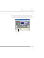
1
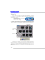
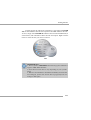
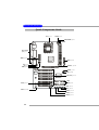
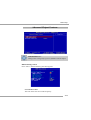
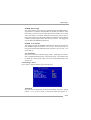
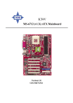
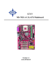
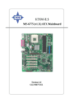
K7T266 Pro2-U/UL MS-6593 (v1.X) ATX Mainboard Version 1.2 G52-M6593X5 i Manual Rev: 1.2 Release Date: Nov. 2002 FCC-B Radio Frequency Interference Statement This equipment has been tested and found to comply with the limits for a class B digital device, pursuant to part 15 of the FCC rules. These limits are designed to provide reasonable protection against harmful interference when the equipment is operated in a commercial environment. This equipment generates, uses and can radiate radio frequency energy and, if not installed and used in accordance with the instruction manual, may cause harmful interference to radio communications. Operation of this equipment in a residential area is likely to cause harmful interference, in which case the user will be required to correct the interference at his own expense. Notice 1 The changes or modifications not expressly approved by the party responsible for compliance could void the user’s authority to operate the equipment. Notice 2 Shielded interface cables and A.C. power cord, if any, must be used in order to comply with the emission limits. VOIR LA NOTICE D’INSTALLATION AVANT DE RACCORDER AU RESEAU. Micro-Star International MS-6593 Tested to comply with FCC Standard For Home or Office Use ii Copyright Notice The material in this document is the intellectual property of MICRO-STAR INTERNATIONAL. We take every care in the preparation of this document, but no guarantee is given as to the correctness of its contents. Our products are under continual improvement and we reserve the right to make changes without notice. Trademarks All trademarks are the properties of their respective owners. AMD, Athlon™, Athlon™ XP, Thoroughbred™, and Duron™ are registered trademarks of AMD Corporation. PS/2 and OS®/2 are registered trademarks of International Business Machines Corporation. Windows ® 95/98/2000/NT/XP are registered trademarks of Microsoft Corporation. Netware® is a registered trademark of Novell, Inc. Award® is a registered trademark of Phoenix Technologies Ltd. AMI® is a registered trademark of American Megatrends Inc. Revision History Revision V1.2 Revision History First release Date Nov. 2002 Technical Support If a problem arises with your system and no solution can be obtained from the user’s manual, please contact your place of purchase or local distributor. Alternatively, please try the following help resources for further guidance. Visit the MSI website for FAQ, technical guide, BIOS updates, driver updates, and other information: http://www.msi.com.tw/ Contact our technical staff at: [email protected] iii Safety Instructions 1. 2. 3. 4. 5. Always read the safety instructions carefully. Keep this User’s Manual for future reference. Keep this equipment away from humidity. Lay this equipment on a reliable flat surface before setting it up. The openings on the enclosure are for air convection hence protects the equipment from overheating. DO NOT COVER THE OPENINGS. 6. Make sure the voltage of the power source and adjust properly 110/220V before connecting the equipment to the power inlet. 7. Place the power cord such a way that people can not step on it. Do not place anything over the power cord. 8. Always Unplug the Power Cord before inserting any add-on card or module. 9. All cautions and warnings on the equipment should be noted. 10. Never pour any liquid into the opening that could damage or cause electrical shock. 11. If any of the following situations arises, get the equipment checked by a service personnel: z The power cord or plug is damaged. z Liquid has penetrated into the equipment. z The equipment has been exposed to moisture. z The equipment has not work well or you can not get it work according to User’s Manual. z The equipment has dropped and damaged. z The equipment has obvious sign of breakage. 12. DO NOT LEAVE THIS EQUIPMENT IN AN ENVIRONMENT UNCONDITIONED, STORAGE TEMPERATURE ABOVE 600 C (1400F), IT MAY DAMAGE THE EQUIPMENT. CAUTION: Danger of explosion if battery is incorrectly replaced. Replace only with the same or equivalent type recommended by the manufacturer. iv CONTENTS Chapter 1. Getting Started ........................................................................ 1-1 Mainboard Specifications .................................................................... 1-2 Mainboard Layout ............................................................................... 1-4 MSI Special Features ........................................................................... 1-5 Fuzzy Logic™ 4 ............................................................................. 1-5 Live BIOS™/Live Driver™ ............................................................ 1-7 Live Monitor™ .............................................................................. 1-7 D-Bracket™ 2 (Optional) ............................................................... 1-8 PC Alert™ 4 ................................................................................. 1-10 Chapter 2. Hardware Setup ....................................................................... 2-1 Quick Components Guide .................................................................... 2-2 Central Processing Unit: CPU .............................................................. 2-3 CPU Installation Procedures ......................................................... 2-3 Memory ................................................................................................ 2-5 Installing DDR Modules ............................................................... 2-5 Power Supply ....................................................................................... 2-6 ATX 20-Pin Power Connector: JWR1 ............................................ 2-6 ATX 12V Power Connector: JPW1 ................................................ 2-6 Back Panel ............................................................................................ 2-7 Connectors ........................................................................................... 2-8 Floppy Disk Drive Connector: FDD1 ............................................. 2-8 Hard Disk Connectors: IDE1 & IDE2 ............................................. 2-8 Fan Power Connectors: CFAN1/SFAN1 ........................................ 2-9 Chassis Intrusion Switch Connector: J3 ........................................ 2-9 CD-In Connector: J10 .................................................................... 2-9 Front Panel Connectors: JFP1 & JFP2 ......................................... 2-10 Front Panel Audio Connector: JAUD1 ........................................ 2-11 Front USB Connectors: JUSB2/JUSB3 ........................................ 2-12 v D-Bracket™ 2 Connector: JLED .................................................. 2-13 Jumpers .............................................................................................. 2-14 Clear CMOS Jumper: JBAT1 ........................................................ 2-14 FSB Clock Jumper: SW3 .............................................................. 2-14 Slots ................................................................................................... 2-15 PCI Interrupt Request Routing .................................................... 2-15 Chapter 3. BIOS Setup .............................................................................. 3-1 Entering Setup ...................................................................................... 3-2 Selecting the First Boot Device ..................................................... 3-2 Control Keys ................................................................................. 3-3 Getting Help .................................................................................. 3-3 The Main Menu ................................................................................... 3-4 Standard CMOS Features .................................................................... 3-6 Advanced BIOS Features .................................................................... 3-7 Advanced Chipset Features ............................................................... 3-11 Power Management Features ............................................................. 3-15 PNP/PCI Configurations ..................................................................... 3-18 Integrated Peripherals ........................................................................ 3-19 PC Health Status ................................................................................ 3-21 Frequency/Voltage Control ................................................................ 3-22 Load High Performance/BIOS Setup Defaults .................................... 3-22 Set Supervisor/User Password ........................................................... 3-23 Appendix: Using 4- or 6-Channel Audio Function .................................... A-1 Using 4- or 6-Channel Audio Function ............................................... A-2 Installing the Audio Driver ........................................................... A-2 Using 4- or 6-Channel Audio Function ........................................ A-2 Testing the Connected Speakers ......................................................... A-6 Testing Each Speaker ................................................................... A-6 Playing KaraOK .................................................................................. A-8 Playing KaraOK ............................................................................ A-8 vi Getting Started Chapter 1. Getting Started Getting Started Thank you for purchasing the K7T266 Pro2-U/UL (MS6593 v1.X) ATX mainboard. The K7T266 Pro2-U/UL are based on VIA® Apollo KT266A & VT8235 chipsets for optimal system efficiency. Designed to fit the advanced AMD® Athlon™, Athlon™ XP or Duron™ processors, the K7T266 Pro2-U/UL deliver a high performance and professional desktop platform solution. 1-1 MS-6593 ATX Mainboard Mainboard Specifications CPU h Supports Socket A (Socket-462) for AMD® Athlon™/Athlon™ XP /Duron™ processors. h Supports up to 2600+ (1.8GHz) or higher speed. Chipset h VIA® KT266A chipset - FSB @200/266MHz. - Supports DDR200/266 memory. - AGP 4X and PCI advanced high performance memory controller. h VIA® VT8235 chipset - Integrated Direct Sound AC97 audio. - Dual channel Ultra DMA 33/66/100/133 master mode EIDE controller. - ACPI & PC2001 compliant enhanced power management. - Integrated USB 2.0 controller. - Integrated LAN MAC. Main Memory h Supports four memory banks using two 184-pin DDR DIMMs. h Supports up to 2GB PC2100/1600 DDR SDRAMs. h Supports 2.5v DDR SDRAM. Slots h One AGP (Accelerated Graphics Port) slot. - Supports AGP 2.0 1x/2x/4x. h Six 32-bit PCI bus slots (support 3.3v/5v PCI bus interface). On-BoardIDE h An IDE controller on the VT8235 chipset provides IDE HDD/CD-ROM with PIO, Bus Master and Ultra DMA133/100/66/33 operation modes. h Can connect up to four IDE devices. On-Board Peripherals h On-Board Peripherals include: - 1 floppy port supports 2 FDDs with 360K, 720K, 1.2M, 1.44M and 2.88Mbytes 1-2 Getting Started - 2 serial ports (COM A + COM B) - 1 parallel port supports SPP/EPP/ECP mode - 1 audio/game port - 6 USB 2.0 ports (Rear * 2/ Front * 4) Audio h RealTek ALC650 6-channel audio. LAN (Optional) h 10/100Mbps Ethernet onboard. BIOS h The mainboard BIOS provides “Plug & Play” BIOS which detects the peripheral devices and expansion cards of the board automatically. h The mainboard provides a Desktop Management Interface (DMI) function which records your mainboard specifications. Dimension h ATX Form Factor: 30.5 cm (L) x 20 cm (W). Mounting h 6 mounting holes. Others h Suspend to RAM/Disk (S3/S4). h PC2001 compliant. h Voltage independent adjustment in CPU, DDR, AGP. 1-3 MS-6593 ATX Mainboard Mainboard Layout Top: Mouse Bottom: Keyboard CFAN1 SOCKET 462 T: LAN Jack (Optional) B: USB Ports Top: Game Port Bottom: Line-Out Line-In Mic FDD 1 DDR 2 ATX Power Supply Bottom: COM A COM B DDR 1 Top: Parallel Port VIA KT266A JPW1 J10 AGP Slot J3 PCI Slot 1 BIOS SFAN1 PCI Slot 2 SW3 Winbond W83697HF PCI Slot 3 VT8235 RealTek ALC650 PCI Slot 4 IDE 1 PCI Slot 5 BATT + JLED PCI Slot 6 IDE 2 JUSB2 JUSB3 JBAT1 JAUD1 JFP1 JFP2 K7T266 Pro2-U/UL (MS-6593 v1.X) ATX Mainboard 1-4 Getting Started MSI Special Features Fuzzy Logic™ 4 The Fuzzy Logic™ 4 utility is a user friendly tool that allows users to view and adjust the current system status. To overclock the CPU FSB (Front Side Bus) frequency under the Windows operating system, click FSB and use the right and left arrow keys to select the desired FSB, and then click Apply to apply the new setup value. To enable the system running at the specified FSB every time when you click Turbo, click Save to save the desired FSB first. If you want to know the maximal CPU overclocking value, click Auto to start testing. The CPU FSB will automatically increase the testing value until the PC reboots. After rebooting, click Turbo to apply the test result. Click Default to restore the default values. Features: Ø MSI Logo Ø CPU Speed Ø Ø Ø Ø Ø Voltage MSI Info CPU Info CPU Fan Speed CPU Temp. links to the MSI Web site allows users to adjust the CPU speed through CPU Multiplier and FSB allows user to adjust the voltage of CPU/Memory/AGP provides information about the mainboard, BIOS and OS provides detailed information about the CPU shows the current running speed of CPU Fan shows the current CPU temperature MSI Reminds You... To adjust the options under CPU Speed and Voltage, use the right and left arrow keys to select the desired value and then click Apply to run the setup value. 1-5 MS-6593 ATX Mainboard Live BIOS™/Live Driver™ The Live BIOS™/Live Driver™ is a tool used to detect and update your BIOS/drivers online so that you don’t need to search for the correct BIOS/driver version throughout the Web site. To use the function, you need to install the “MSI Live Update 2” application. After installation, the “MSI Live Update 2” icon (as shown on the right) will appear on the screen. Double click the “MSI Live Update 2” icon, and the following screen will appear: Five buttons are placed on the leftmost pane of the screen. Click the desired button to start the update process. z Live BIOS – Updates the BIOS online. z Live Driver – Updates the drivers online. z Live VGA BIOS – Updates the VGA BIOS online. z Live VGA Driver – Updates the VGA driver online. z Live Utility – Updates the utilities online. If the product you purchased does not support any of the functions listed above, a “sorry” message is displayed. For more information on the update instructions, insert the companion CD and refer to the “Live Update Guide” under the “Manual” Tab. 1-6 Getting Started Live Monitor™ The Live Monitor™ is a tool used to schedule the search for the latest BIOS/drivers version on the MSI Web site. To use the function, you need to install the “MSI Live Update 2” application. After installation, the “MSI Live Monitor” icon (as shown on the right) will appear on the screen. Double click this icon to run the application. Double click the “MSI Live Monitor” icon at the lower-right corner of the taskbar, and the following dialog box will appear. You can specify how often the system will automatically search for the BIOS/drivers version, or change the LAN settings right from the dialog box. You can right-click the MSI Live Monitor icon to perform the functions listed below: z Auto Search – Searches for the BIOS/drivers version you need immediately. z View Last Result – Allows you to view the last search result if there is any. z Preference – Configures the Search function, including the Search schedule. z Exit – Exits the Live Monitor™ application. z FAQ – Provides a link to a database which contents various possible questions about MSI's products for users to inquire. 1-7 MS-6593 ATX Mainboard D-Bracket™ 2 (Optional) D-Bracket™ 2 is an external USB bracket integrating four Diagnostic LEDs, which use graphic signal display to help users understand their system. The LEDs provide up to 16 combinations of signals to debug the system. The 4 LEDs can debug all problems that fail the system, such as VGA, RAM or other failures. This special feature is very useful for the overclocking users. These users can use the feature to detect if there are any problems or failures. D-Bracket™ 2 supports both USB 1.1 & 2.0 spec. D-Bracket™ 2 1 3 2 4 Green Red TM D-Bracket 2 Description System Power ON 1 3 2 4 - The D-LED will hang here if the processor is damaged or not installed properly. Early Chipset Initialization Memory Detection Test - Testing onboard memory size. The D-LED will hang if the memory module is damaged or not installed properly. Decompressing BIOS image to RAM for fast booting. Initializing Keyboard Controller. Testing VGA BIOS - This will start writing VGA sign-on message to the screen. 1-8 Getting Started TM D-Bracket 2 Description Processor Initialization 1 3 2 4 - This will show information regarding the processor (like brand name, system bus, etc…) Testing RTC (Real Time Clock) Initializing Video Interface - This will start detecting CPU clock, checking type of video onboard. Then, detect and initialize the video adapter. BIOS Sign On - This will start showing information about logo, processor brand name, etc…. Testing Base and Extended Memory - Testing base memory from 240K to 640K and extended memory above 1MB using various patterns. Assign Resources to all ISA. Initializing Hard Drive Controller - This will initialize IDE drive and controller. Initializing Floppy Drive Controller - This will initializing Floppy Drive and controller. Boot Attempt - This will set low stack and boot via INT 19h. Operating System Booting 1-9 MS-6593 ATX Mainboard PC Alert™ 4 The PC AlertTM 4 is a utility you can find in the CD-ROM disk. The utility is just like your PC doctor that can detect the following PC hardware status during real time operation: Ø monitor CPU & system temperatures Ø monitor fan speeds Ø monitor system voltages If one of the items above is abnormal, the program main screen will be immediately shown on the screen, with the abnormal item highlighted in red. This will continue to be shown until the condition returns to the normal status. Adjusting Keys Temperature Modes COOLER XP Users can use the Adjusting Keys to change the minimum and maximum threshold of each item for the system to send out a warning message. Click Temperature to select the temperature modes of either Fahrenheit (℉) or Celsius (℃). The PC Alert™ 4 icon on the Status Area will show the current CPU temperature. 1-10 Getting Started To better protect the CPU from overheating, a new feature, COOLER XP, has been added to decrease the temperature of AMD Athlon™ XP CPU. To do so, simply click COOLER XP and the screen will show the Cute skin (as shown below) with information about the CPU and chipset. Right-click the mouse to select the skin you want to switch to. Cute MSI Reminds You... 1. The new feature COOLER XP will work only if your mainboard supports AMD Athlon XP CPU. 2. Items shown on PC Alert 4 vary depending on your system’s status. 3. Whenever the minimum or maximum threshold of each item has been changed, please close the PC Alert 4 program for the new settings to take effect. 1-11 Hardware Setup Chapter 2. Hardware Setup Hardware Setup This chapter tells you how to install the CPU, memory modules, and expansion cards, as well as how to setup the jumpers on the mainboard. Also, it provides the instructions on connecting the peripheral devices, such the mouse, keyboard, etc. While doing the installation, be careful in holding the components and follow the installation procedures. 2-1 MS-6593 ATX Mainboard Quick Components Guide CPU, p.2-3 CFAN1, p.2-9 DDR DIMMs, p.2-5 Back Panel I/O, p.2-7 JWR1, p.2-6 FDD1, p.2-8 J10, p.2-9 J3, p.2-9 JPW1, p.2-6 AGP Slot, p.2-15 SFAN1, p.2-9 SW3, p.2-14 PCI Slots, p.2-15 JLED, p.2-13 IDE1 IDE2, p.2-8 JFP2, p.2-10 JBAT1, p.2-14 JFP1, p.2-10 JUSB3, p.2-12 JUSB2, p.2-12 JAUD1, p.2-11 2-2 Hardware Setup Central Processing Unit: CPU The mainboard supports AMD® Athlon™, Athlon™ XP and Duron™ processors in the 462 pin package. The mainboard uses a CPU socket called Socket A for easy CPU installation. When you are installing the CPU, make sure the CPU has a heat sink and a cooling fan attached on the top to prevent overheating. If you do not find the heat sink and cooling fan, contact your dealer to purchase and install them before turning on the computer. CPU Installation Procedures Open Lever 1. Pull the lever sideways away from the socket. Then, raise the lever up to a 90-degree angle. 2. Look for the cut edge. The cut edge should point towards the lever pivot. The CPU will only fit in the correct orientation. 3. Hold the CPU down firmly, Sliding Plate Cut edge Close Lever and then close the lever to complete the installation. MSI Reminds You... Overheating will seriously damage the CPU and system, always make sure the cooling fan can work properly to protect the CPU from overheating. 2-3 MS-6593 ATX Mainboard WARNING! Thermal Issue for CPU AMD Athlon™/Duron™/Athlon™ XP processor requires a LARGER heatsink and fan. You also need to add thermal grease between the CPU and heatsink to improve heat dissipation. Then, make sure that the CPU and heatsink are securely fastened and in good contact with each other. These are needed to prevent damaging the processor and ensuring reliable operation. If you want to get more information on the proper cooling, you can visit AMD’s website for reference. MSI Reminds You... Replacing CPU While replacing the CPU, always turn off the ATX power supply or unplug the power supply’s power cord from grounded outlet first to ensure the safety of CPU. Overclocking This motherboard is designed to support overclocking. However, please make sure your components are able to tolerate such abnormal setting, while doing overclocking. Any attempt to operate beyond product specifications is not recommended. We do not guarantee the damages or risks caused by inadequate operation or beyond product specifications. 2-4 Hardware Setup Memory The mainboard provides 2 slots for 184-pin DDR SDRAM DIMM (Double In-Line Memory Module) modules and supports the memory size up to 2GB. You can install PC2100/DDR266 or PC1600/DDR200 modules on the DDR DIMM slots (DDR 1~2). DDR DIMM Slots (DDR 1~2) Installing DDR Modules 1. The DDR DIMM has only one notch on the center of module. The module will only fit in the right orientation. 2. Insert the DIMM memory module vertically into the DIMM slot. Then push it in until the golden finger on the memory module is deeply inserted in the socket. 3. The plastic clip at each side of the DIMM slot will automatically close. Volt Notch 2-5 MS-6593 ATX Mainboard Power Supply The mainboard supports ATX power supply for the power system. Before inserting the power supply connector, always make sure that all components are installed properly to ensure that no damage will be caused. ATX 20-Pin Power Connector: JWR1 This connector allows you to connect to an ATX power supply. To connect to the ATX power supply, make sure the plug of the power supply is inserted in the proper orientation and the pins are aligned. Then push down the power supply firmly into the connector. ATX 12V Power Connector: JPW1 This 12V power connector is used to provide power to the CPU. 11 1 20 10 JWR1 1 3 2 4 JPW1 JWR1 Pin Definition JPW1 Pin Definition 2-6 PIN SIGNAL 1 2 3 4 GND GND 12V 12V PIN SIGNAL PIN SIGNAL 1 2 3 4 5 6 7 8 9 3.3V 3.3V GND 5V GND 5V GND PW_OK 5V_SB 10 12V 11 12 13 14 15 16 17 18 19 20 3.3V -12V GND PS_ON GND GND GND -5V 5V 5V Hardware Setup Back Panel LAN (Optional) Mouse Keyboard USB COM A Mouse Connector Pin6 NC COM B L-out L-in MIC Midi/Joystick Pin5 Mouse Clock Pin4 VCC Pin3 GND Pin2 NC Pin1 Mouse DATA Audio Ports Keyboard Connector Pin6 NC Pin5 KBD Clock Pin4 VCC Pin3 GND Pin2 NC Pin1 KBD DATA USB Ports 1 Midi/Joystick Parallel Line Out Line In MIC RJ-45 LAN Jack 2 3 4 8 PIN 1 2 3 4 SIGNAL VCC -Data +Data GND PIN 1 2 3 4 SIGNAL TDP TDN RDP NC 1 PIN 5 6 7 8 SIGNAL NC RDN NC NC 2-7 MS-6593 ATX Mainboard Connectors The mainboard provides connectors to connect to FDD, IDE HDD, case, modem, LAN, USB Ports, IR module and CPU/System/Power Supply FAN. Floppy Disk Drive Connector: FDD1 The mainboard provides a standard floppy disk drive connector that supports 360K, 720K, 1.2M, 1.44M and 2.88M floppy disk types. Hard Disk Connectors: IDE1 & IDE2 The mainboard has a 32-bit Enhanced PCI IDE and Ultra DMA 33/66/ 100/133 controller that provides PIO mode 0~4, Bus Master, and Ultra DMA 33/66/100/133 function. You can connect up to four hard disk drives, CDROM, 120MB Floppy (reserved for future BIOS) and other devices. FDD1 IDE 1 IDE 2 IDE1 (Primary IDE Connector) The first hard drive should always be connected to IDE1. IDE1 can connect a Master and a Slave drive. You must configure second hard drive to Slave mode by setting the jumper accordingly. IDE2 (Secondary IDE Connector) IDE2 can also connect a Master and a Slave drive. 2-8 Hardware Setup Fan Power Connectors: CFAN1/SFAN1 The CFAN1 (processor fan) and SFAN1 (system fan) support system cooling fan with +12V. Chassis Intrusion Switch Connector: J3 This connector is connected to a 2-pin chassis switch. If the chassis is open, the switch will be short. The system will record this status and show a warning message on the screen. To clear the warning, you must enter the BIOS utility and clear the record. CD-In Connector: J10 The connector is for CD-ROM audio connector. SENSOR +12V GND J10 CFAN1 R GND L 2 1 GND CINTRU SENSOR +12V GND SFAN1 J3 MSI Reminds You... Always consult the vendors for proper CPU cooling fan. 2-9 MS-6593 ATX Mainboard Front Panel Connectors: JFP1 & JFP2 The mainboard provides two front panel connectors for electrical connection to the front panel switches and LEDs. JFP1 is compliant with Intel® Front Panel I/O Connectivity Design Guide. Power Power LED Switch JFP1 2 1 10 9 HDD Reset LED Switch Speaker JFP2 2 1 8 7 Power LED JFP1 Pin Definition PIN SIGNAL DESCRIPTION 1 2 3 4 5 6 7 8 9 HD_LED_P FP PWR/SLP HD_LED_N FP PWR/SLP RST_SW_N PWR_SW_P RST_SW_P PWR_SW_N RSVD_DNU Hard disk LED pull-up MSG LED pull-up Hard disk active LED MSG LED pull-up Reset Switch low reference pull-down to GND Power Switch high reference pull-up Reset Switch high reference pull-up Power Switch low reference pull-down to GND Reserved. Do not use. JFP2 Pin Definition 2-10 PIN SIGNAL PIN SIGNAL 1 GND 2 SPK- 3 5 7 SLED PLED NC 4 6 8 BUZ+ BUZSPK+ Hardware Setup Front Panel Audio Connector: JAUD1 The JAUD1 front panel audio connector allows you to connect to the front panel audio and is compliant with Intel® Front Panel I/O Connectivity Design Guide. 2 10 1 9 JAUD1 Pin Definition PIN SIGNAL DESCRIPTION 1 2 3 4 5 6 7 8 9 10 AUD_MIC AUD_GND AUD_MIC_BIAS AUD_VCC AUD_FPOUT_R AUD_RET_R HP_ON KEY AUD_FPOUT_L AUD_RET_L Front panel microphone input signal Ground used by analog audio circuits Microphone power Filtered +5V used by analog audio circuits Right channel audio signal to front panel Right channel audio signal return from front panel Reserved for future use to control headphone amplifier No pin Left channel audio signal to front panel Left channel audio signal return from front panel MSI Reminds You... If you don’t want to connect to the front audio header, pins 5 & 6, 9 & 10 have to be jumpered in order to have signal output directed to the rear audio ports. Otherwise, the Line-Out connector on the back panel will not function. 6 10 5 9 2-11 MS-6593 ATX Mainboard Front USB Connectors: JUSB2/JUSB3 The mainboard provides two USB 2.0 pin headers JUSB2 & JUSB3 (optional USB 2.0 bracket available) that are compliant with Intel® I/O Connectivity Design Guide. USB 2.0 technology increases data transfer rate up to a maximum throughput of 480Mbps, which is 40 times faster than USB 1.1, and is ideal for connecting high-speed USB interface peripherals such as USB HDD, digital cameras, MP3 players, printers, modems and the like. 10 9 2 1 10 9 2 1 JUSB2 JUSB3 (USB 2.0/Intel spec) (USB 2.0/Intel spec) JUSB2/3 Pin Definition Connected to JUSB2 or JUSB3 2-12 PIN SIGNAL PIN SIGNAL 1 USBPWR 2 USBPWR 3 USBP2- 4 USBP3- 5 USBP2+ 6 USBP3+ 7 GND 8 GND 9 NC 10 USBOC USB 2.0 Bracket (Optional) Hardware Setup D-Bracket™ 2 Connector: JLED The mainboard comes with a JLED connector for you to connect to DBracket™ 2. D-Bracket™ 2 is a USB Bracket that supports both USB1.1 & 2. 0 spec. It integrates four LEDs and allows users to identify system problem through 16 various combinations of LED signals. For definitions of 16 signal combinations, please refer to D-Bracket™ 2 (Optional) in Chapter 1. Pin Definition Pin Signal 1 2 3 4 5 6 7 8 9 10 DBG1 (high for green color) DBR1 (high for red color) DBG2 (high for green color) DBR2 (high for red color) DBG3 (high for green color) DBR3 (high for red color) DBG4 (high for green color) DBR4 (high for red color) Key NC 9 10 1 2 JLED Connected to JLED Connected to JUSB2 or JUSB3 D-Bracket™ 2 (Optional) LEDs 2-13 MS-6593 ATX Mainboard Jumpers The motherboard provides the following jumpers for you to set the computer’s function. This section will explain how to change your motherboard’s function through the use of jumpers. Clear CMOS Jumper: JBAT1 There is a CMOS RAM on board that has a power supply from external battery to keep the data of system configuration. With the CMOS RAM, the system can automatically boot OS every time it is turned on. If you want to clear the system configuration, use the JBAT1 (Clear CMOS Jumper ) to clear data. FSB Clock Jumper: SW3 This jumper provides 100MHz and 133MHz Front Side Bus frequency selection. 1 SW3 1 JBAT1 1 3 Keep Data 1 3 Clear Data 1 3 FSB = 133MHz 1 3 FSB = 100MHz MSI Reminds You... You can clear CMOS by shorting 2-3 pin while the system is off. Then return to 1-2 pin position. Avoid clearing the CMOS while the system is on; it will damage the mainboard. 2-14 Hardware Setup Slots The motherboard provides one AGP slot and six 32-bit PCI bus slots. AGP Slot PCI Slots PCI Interrupt Request Routing The IRQ, acronym of interrupt request line and pronounced I-R-Q, are hardware lines over which devices can send interrupt signals to the microprocessor. The PCI IRQ pins are typically connected to the PCI bus INT A# ~ INT D# pins as follows: Order 1 Order 2 Order 3 Order 4 PCI Slot 1 INT A# INT B# INT C# INT D# PCI Slot 2 INT B# INT C# INT D# INT A# PCI Slot 3 INT C# INT D# INT A# INT B# PCI Slot 4 INT D# INT A# INT B# INT C# PCI Slot 5 INT B# INT C# INT D# INT A# PCI Slot 6 INT C# INT D# INT A# INT B# 2-15 BIOS Setup Chapter 3. BIOS Setup BIOS Setup This chapter provides information on the BIOS Setup program and allows you to configure the system for optimum use. You may need to run the Setup program when: An error message appears on the screen during the system booting up, and requests you to run SETUP. You want to change the default settings for customized features. 3-1 MS-6593 ATX Mainboard Entering Setup Power on the computer and the system will start POST (Power On Self Test) process. When the message below appears on the screen, press <DEL> key to enter Setup. DEL:Setup F11:Boot Menu F12:Network boot TAB:Logo If the message disappears before you respond and you still wish to enter Setup, restart the system by turning it OFF and On or pressing the RESET button. You may also restart the system by simultaneously pressing <Ctrl>, <Alt>, and <Delete> keys. Selecting the First Boot Device You are allowed to select the 1st boot device without entering the BIOS setup utility by pressing <F11>. When the same message as listed above appears on the screen, press <F11> to trigger the boot menu. The POST messages might pass by too quickly for you to respond in time. If so, restart the system and press <F11> after around 2 or 3 seconds to activate the boot menu similar to the following. Select First Boot Device Floppy IDE-0 CDROM : 1st Floppy : IBM-DTLA-307038 : ATAPI CD-ROM DRIVE 40X M [Up/Dn] Select [RETURN] Boot [ESC] cancel The boot menu will list all the bootable devices. Select the one you want to boot from by using arrow keys and then pressing <Enter>. The system will boot from the selected device. The selection will not make changes to the settings in the BIOS setup utility, so next time when you power on the system, it will still use the original first boot device to boot up. 3-2 BIOS Setup Control Keys <↑> Move to the previous item <↓> Move to the next item <←> Move to the item in the left hand <→> Move to the item in the right hand <Enter> Select the item <Esc> Jumps to the Exit menu or returns to the main menu from a submenu <+/PU> Increase the numeric value or make changes <-/PD> Decrease the numeric value or make changes <F5> Restore the previous CMOS value from CMOS, only for Option Page Setup Menu <F6> Load High Performance Defaults <F7> Load BIOS Setup Defaults <F10> Save all the CMOS changes and exit Getting Help After entering the Setup utility, the first screen you see is the Main Menu. Main Menu The main menu displays the setup categories the BIOS supplies. You can use the arrow keys ( ↑↓ ) to select the item. The on-line description for the selected setup category is displayed at the bottom of the screen. Default Settings The BIOS setup program contains two kinds of default settings: the BIOS Setup and High Performance Defaults. BIOS Setup Defaults provide stable performance settings for all devices and the system, while High Performance Defaults provide the best system performance but may affect the system stability. 3-3 MS-6593 ATX Mainboard The Main Menu Once you enter AMIBIOS NEW SETUP UTILITY, the Main Menu will appear on the screen. The Main Menu displays twelve configurable functions and two exit choices. Use arrow keys to move among the items and press <Enter> to enter the sub-menu. Standard CMOS Features Use this menu for basic system configurations, such as time, date etc. Advanced BIOS Features Use this menu to setup the items of AMI® special enhanced features. Advanced Chipset Features Use this menu to change the values in the chipset registers and optimize your system’s performance. Power Management Features Use this menu to specify your settings for power management. PNP/PCI Configurations This entry appears if your system supports PnP/PCI. 3-4 BIOS Setup Integrated Peripherals Use this menu to specify your settings for integrated peripherals. PC Health Status This entry shows your PC health status. Frequency/Voltage Control Use this menu to specify your settings for frequency/voltage control. Set Supervisor Password Use this menu to set Supervisor Password. Set User Password Use this menu to set User Password. Load High Performance Defaults Use this menu to load the BIOS values for the best system performance, but the system stability may be affected. Load BIOS Setup Defaults Use this menu to load factory default settings into the BIOS for stable system performance operations. Save & Exit Setup Save changes to CMOS and exit setup. Exit Without Saving Abandon all changes and exit setup. 3-5 MS-6593 ATX Mainboard Standard CMOS Features System Time This allows you to set the system time that you want (usually the current time). The time format is <hour> <minute> <second>. System Date This allows you to set the system to the date that you want (usually the current date). The format is <day><month> <date> <year>. Primary/Secondary IDE Master/Slave Press PgUp/<+> or PgDn/<-> to select the hard disk drive type. The specification of hard disk drive will show up on the right hand according to your selection. Floppy Drive A:/B: This item allows you to set the type of floppy drives installed. Boot Sector Virus Protection The item is to set the Virus Warning feature for IDE Hard Disk boot sector protection. When Enabled, BIOS will issue a virus warning message and beep if a write to the boot sector or the partition table of the HDD is attempted. Setting options: Disabled and Enabled. MSI Reminds You... This feature only protects the boot sector, not the whole hard disk. 3-6 BIOS Setup Advanced BIOS Features Quick Boot Setting the item to Enabled allows the system to boot within 5 seconds since it will skip some check items. Available options: Enabled, Disabled. Full Screen Logo Show This item enables you to show the company logo on the bootup screen. Settings are: Enabled Shows a still image (logo) on the full screen at boot. Disabled Shows the POST messages at boot. Boot Sequency Press <Enter> to enter the sub-menu screen. 1st/2nd/3rd Boot Device The items allow you to set the sequence of boot devices where AMIBIOS attempts to load the operating system. 3-7 MS-6593 ATX Mainboard MSI Reminds You... Available settings for “1st/2nd/3rd Boot Device” vary depending on the bootable devices you have installed. For example, if you did not install a floppy drive, the setting “Floppy” does not show up. Try Other Boot Devices Setting the option to Yes allows the system to try to boot from other devices if the system fails to boot from the 1st/2nd/3rd boot device. S.M.A.R.T. for Hard Disks This allows you to activate the S.M.A.R.T. (Self-Monitoring Analysis & Reporting Technology) capability for the hard disks. S.M.A.R.T is a utility that monitors your disk status to predict hard disk failure. This gives you an opportunity to move data from a hard disk that is going to fail to a safe place before the hard disk becomes offline. Settings: Enabled, Disabled. BootUp Num-Lock This item is to set the Num Lock status when the system is powered on. Setting to On will turn on the Num Lock key when the system is powered on. Setting to Off will allow end users to use the arrow keys on the numeric keypad. Floppy Drive Swap Setting to Enabled will swap floppy drives A: and B:. Floppy Drive Seek This setting causes the BIOS to search for floppy disk drives at boot time. When enabled, the BIOS will activate the floppy disk drives during the boot process. The drive activity light will come on and the head will move back and forth once. First A: will be done and then B: if it exists. Primary Display This configures the primary subsystem in the computer. Available options: Mono (monochrome), CGA40x25, CGA80x25, VGA/EGA, Absent. Password Check This specifies the type of AMIBIOS password protection that is implemented. Setting options are described below. 3-8 BIOS Setup Option Setup Always Description The password prompt appears only when end users try to run Setup. A password prompt appears every time when the computer is powered on or when end users try to run Setup. Boot To OS/2 This allows you to run the OS/2® operating system with DRAM larger than 64MB. When you choose No, you cannot run the OS/2® operating system with DRAM larger than 64MB. But it is possible if you choose Yes. Internal Cache Cache memory is additional memory that is much faster than conventional DRAM (system memory). When the CPU requests data, the system transfers the requested data from the main DRAM into cache memory, for even faster access by the CPU. The setting controls the internal cache (also known as L1 or level 1 cache). Setting to WriteBack will speed up the system performance. System BIOS Cacheable Selecting Enabled allows caching of the system BIOS ROM at F0000hFFFFFh, resulting in better system performance. However, if any program writes to this memory area, a system error may result. Setting options: Enabled, Disabled. C000, 32k Shadow This item specifies how the contents of the adapter ROM named in the item are handled. Settings are described below: Option Description Disabled Enabled The specified ROM is not copied to RAM. The contents of specified ROM are copied to RAM for faster system performance. The contents of specified ROM are not only copied to RAM, the contents of the ROM area can be written to and read from cache memory. Cached 3-9 MS-6593 ATX Mainboard APIC Function This field is used to enable or disable the APIC (Advanced Programmable Interrupt Controller). Due to compliance to PC2001 design guide, the system is able to run in APIC mode. Enabling APIC mode will expand available IRQs resources for the system. Settings: Enabled, Disabled. MPS Table Version This field allows you to select which MPS (Multi-Processor Specification) version to be used for the operating system. You need to select the MPS version supported by your operating system. To find out which version to use, consult the vendor of your operating system. Settings: 1.4, 1.1. 3-10 BIOS Setup Advanced Chipset Features MSI Reminds You... Change these settings only if you are familiar with the chipset. DRAM Timing Control Press <Enter> and the following sub-menu appears. Current Host Clock This item shows the current CPU frequency. 3-11 MS-6593 ATX Mainboard Configure SDRAM Timing by Selects whether DRAM timing is controlled by the SPD (Serial Presence Detect) EEPROM on the DRAM module. Setting to SPD enables SDRAM Frequency, SDRAM CAS# Latency, Row Precharge Time, RAS Pulse Width, RAS to CAS Delay and SDRAM Bank Interleave automatically to be determined by BIOS based on the configurations on the SPD. Selecting User allows users to configure these fields manually. SDRAM Frequency Use this item to configure the clock frequency of the installed SDRAM. SDRAM CAS# Latency This controls the timing delay (in clock cycles) before SDRAM starts a read command after receiving it. 2 (clocks) increases the system performance the most while 3 (clocks) provides the most stable performance. Row Precharge Time This item controls the number of cycles for Row Address Strobe (RAS) to be allowed to precharge. If insufficient time is allowed for the RAS to accumulate its charge before DRAM refresh, refresh may be incomplete and DRAM may fail to retain data. This item applies only when synchronous DRAM is installed in the system. RAS Pulse Width This setting allows you to select the number of clock cycles allotted for the RAS pulse width, according to DRAM specifications. The less the clock cycles, the faster the DRAM performance. RAS to CAS Delay When DRAM is refreshed, both rows and columns are addressed separately. This setup item allows you to determine the timing of the transition from RAS (row address strobe) to CAS (column address strobe). The less the clock cycles, the faster the DRAM performance. SDRAM Bank Interleave This field selects 2-bank or 4-bank interleave for the installed SDRAM. Disable the function if 16MB SDRAM is installed. 3-12 BIOS Setup SDRAM Burst Length This setting allows you to set the size of Burst-Length for DRAM. Bursting feature is a technique that DRAM itself predicts the address of the next memory location to be accessed after the first address is accessed. To use the feature, you need to define the burst length, which is the actual length of burst plus the starting address and allows internal address counter to properly generate the next memory location. The bigger the size, the faster the DRAM performance. SDRAM 1T Command This setting controls the SDRAM command rate. Selecting Enabled allows SDRAM signal controller to run at 1T (T=clock cycles) rate. Selecting Disabled makes SDRAM signal controller run at 2T rate. 1T is faster than 2T. Fast Command This item controls the internal timing of CPU. Selecting Ultra allows CPU to handle data/instructions at the fastest speed. Fast enables CPU to handle at a faster speed, while Normal let CPU handle them at the slowest rate. AGP Timing Control Press <Enter> and the following sub-menu appears. AGP Mode The item sets an appropriate mode for the installed AGP card. Setting options: 1x, 2x, 4x, Auto. Select 4x only if your AGP card supports it. 3-13 MS-6593 ATX Mainboard AGP Comp. Driving This field is used to adjust the AGP driving force. Selecting Manual allows you to select an AGP driving force in Manual AGP Comp. Driving. It is strongly recommended to select Auto to avoid causing any system error. Manual AGP Comp. Driving This item specifies an AGP driving force. AGP Fast Write This field enables or disables the AGP Fast Write feature. The Fast Write technology allows the CPU to write directly to the graphics card without passing anything through the system memory and improves the AGP 4X speed. Select Enabled only when the installed AGP card supports the function. AGP Aperture Size This setting controls just how much system RAM can be allocated to AGP for video purposes. The aperture is a portion of the PCI memory address range dedicated to graphics memory address space. Host cycles that hit the aperture range are forwarded to the AGP without any translation. AGP Master 1 W/S Write The field allows users to insert one wait state into the AGP write cycle. AGP Master 1 W/S Read The field allows users to insert one wait state into the AGP read cycle. AGP Read Synchronization The field allows you to enable or disable the AGP Read Synchronization feature. PCI Delay Transaction The chipset has an embedded 32-bit posted write buffer to support delayed transactions cycles so that transactions to and from the ISA bus are buffered and PCI bus can perform other transactions while the ISA transaction is underway. Select Enabled to support compliance with PCI specification version 2.1. Setting options: Enabled, Disabled. 3-14 BIOS Setup Power Management Features MSI Reminds You... S3-related functions described in this section are available only when your BIOS supports S3 sleep mode. IPCA Function This item is to activate the ACPI (Advanced Configuration and Power Management Interface) function. If your operating system is ACPI-aware, such as Windows 98SE/2000/ME, select Yes. ACPI Standby State This item specifies the power saving modes for ACPI function. If your operating system supports ACPI, such as Windows 98SE, Windows ME and Windows 2000, you can choose to enter the Standby mode in S1(POS) or S3 (STR) fashion through the setting of this field. Call VGA at S3 Resuming Selecting Enabled allows BIOS to call VGA BIOS to initialize the VGA card when system wakes up (resumes) from S3 sleep state. The system resume time is shortened when you disable the function, but system will need an AGP driver to initialize the VGA card. Therefore, if the AGP driver of the card does not support the initialization feature, the display may work abnormally or not function after resuming from S3. 3-15 MS-6593 ATX Mainboard USB Wakeup From S3 This item allows the activity of the USB device to wake up the system from S3 (Suspend to RAM) sleep state. Power Management/APM Setting to Enabled will activate an Advanced Power Management (APM) device to enhance Max Saving mode and stop CPU internal clock. Power/Sleep LED This item configures how the system uses power LED on the case to indicate the sleep/suspend state. Available options are: Single LED The power LED turns off to indicate the sleep/suspend state. Dual LED The power LED changes its color to indicate the sleep/ suspend state. Suspend Time Out (Minute) After the selected period of system inactivity, all devices except the CPU shut off. Display Activity These items specify if the BIOS will monitor the activity of the specified hardware peripheral or component. If set to Monitor, any activity detected on the specified hardware peripheral or component will wake up the system or prevent the system from entering the power saving modes. CPU Critical Temperature If the CPU temperature reaches the upper limit preset in this setting, the warning mechanism will be activated. This helps you to prevent the CPU overheating problem. Power Button Function This feature sets the function of the power button. Settings are: On/Off The power button functions as normal power off button. Suspend When you press the power button, the computer enters the suspend/sleep mode, but if the button is pressed for more than four seconds, the computer is turned off. After AC Power Loss This setting specifies whether your system will reboot after a power failure or 3-16 BIOS Setup interrupt occurs. Setting to Last State will restore the system to the previous status before power failure or interrupt occurred. Set WakeUp Events Press <Enter> and the following sub-menu appears. Wake Up On PME, Resume On KBC (with “Wake-Up Key” and “Wake-Up Password”), Resume On PS/2 Mouse These fields specify whether the system will be awakened from power saving modes when activity or input signal of the specified hardware peripheral or component is detected. MSI Reminds You... 1. For “Wake-Up Key” function, the option “Specific Key” refers to the password you specify in the “Wake-Up Password” field. Once you set up a password, it will disable “Resume on PS/2 Mouse”. 2. For “Resume On PS/2 Mouse” function, you need to left-click the mouse to power on the system if the function is enabled. Resume By Alarm This is used to enable or disable the feature of booting up the system on a scheduled time/date from the soft off (S5) state. Alarm Date/Hour/Minute/Second If Resume By Alarm is set to Enabled, the system will automatically resume (boot up) on a specific date/hour/minute/second specified here. 3-17 MS-6593 ATX Mainboard PNP/PCI Configurations Plug and Play Aware O/S When set to Yes, BIOS will only initialize the PnP cards used for booting. The rest of the cards will be initialized by the PnP operating system like Windows® 98, 2000 or ME. When set to No, BIOS will initialize all the PnP cards. Clear NVRAM The ESCD (Extended System Configuration Data) NVRAM (Non-volatile Random Access Memory) is where the BIOS stores resource information for both PNP and non-PNP devices in a bit string format. When the item is set to Yes, the system will reset ESCD NVRAM right after the system is booted up and then set the setting of the item back to No automatically. PCI Latency Timer This item controls how long each PCI device can hold the bus before another takes over. When set to higher values, every PCI device can conduct transactions for a longer time and thus improve the effective PCI bandwidth. PCI IDE BusMaster Set this option to Enabled to specify that the IDE controller on the PCI local bus has bus mastering capability. Primary Graphics Adaptor This setting specifies which VGA card is your primary graphics adapter. PCI Slot1 IRQ, PCI Slot2/5 IRQ, PCI Slot3/6 IRQ, PCI Slot4 IRQ These items specify the IRQ line for each PCI slot. 3-18 BIOS Setup Integrated Peripherals FDC Function This is used to enable or disable the onboard Floppy controller. Serial Port 1/2 These items specify the base I/O port addresses of the onboard Serial Port 1 (COM A)/Serial Port 2 (COM B). OnBoard Parallel Port This field specifies the base I/O port address of the onboard parallel port. Parallel Port Mode This item selects the operation mode for the onboard parallel port. EPP Version The item selects the EPP version used by the parallel port if the port is set to EPP mode. Parallel Port IRQ When OnBoard Parallel Port is set to Auto, the item shows Auto indicating that BIOS determines the IRQ for the parallel port automatically. 3-19 MS-6593 ATX Mainboard Parallel Port DMA This feature needs to be configured only when Parallel Port Mode is set to the ECP mode. OnBoard Midi Port The field specifies the base I/O port address for the onboard Midi Port. Midi IRQ Select The item is used to select the IRQ line for onboard Midi port. OnBoard Game Port This item is used to specify the address for the onboard game port. OnBoard IDE This setting controls the onboard IDE controller. AC’97 Audio The item is used to enable or disable the onboard AC’97 (Audio Codec’97) controller. USB Controller This setting is used to enable/disable the onboard USB ports. USB Legacy Support Set to All Device if you need to use any USB device in the operating system that does not support or have any USB driver installed, such as DOS and SCO Unix. Set to No Mice only if you want to use any USB device other than the USB mouse. Port 64/60 Emulation This field controls the USB Port 64/60 Emulation function. When the function is enabled, the USB keyboard is allowed to type some special combination keys. 3-20 BIOS Setup PC Health Status Chassis Intrusion The field enables or disables the feature of recording the chassis intrusion status and issuing a warning message if the chassis is once opened. To clear the warning message, set the field to Reset. The setting of the field will automatically return to Enabled later. CPU Fan Detection When enabled, the system will automatically monitor the CPU fan during boot-up. If it detects that the CPU fan is not rotating, the system will show an error message on the screen and halt the boot-up process. CPU/System Temperature, CPU/System Fan Speed, Vcore, +5.0V, +12. 0V, -12.0V, -5.0V, Battery, +5V SB These items display the current status of all of the monitored hardware devices/components such as CPU voltages, temperatures and all fans’ speeds. 3-21 MS-6593 ATX Mainboard Frequency/Voltage Control Spread Spectrum When the motherboard’s clock generator pulses, the extreme values (spikes) of the pulses creates EMI (Electromagnetic Interference). The Spread Spectrum function reduces the EMI generated by modulating the pulses. Remember to disable Spread Spectrum if you are overclocking. CPU FSB Clock This item allows you to select the CPU Front Side Bus frequency (in MHz) and overclock the processor by adjusting the FSB clock to a higher frequency. CPU Ratio/Vcore (V) The settings are used to adjust the CPU clock multiplier (ratio) and CPU core voltage (Vcore) for overclocking purposes. Changing CPU Ratio/Vcore could result in the instability of the system; therefore, it is NOT recommended to change the default setting for long-term usage. DDR Voltage (V) Adjusting the DDR voltage can increase the DDR speed. Any changes made to this setting may cause a stability issue, so changing the DDR voltage for long-term purpose is NOT recommended. AGP Voltage (V) Adjusting the AGP voltage increases the performance of your AGP display card when overclocking, but the stability may be affected. 3-22 BIOS Setup Set Supervisor/User Password Type the password, up to six characters in length, and press <Enter>. The password typed now will replace any previously set password from CMOS memory. You may also press <Esc> to abort the setting and not enter a password. To clear a set password, just press <Enter> when you are prompted to enter the password. Once the password is disabled, the system will boot and you can enter Setup without entering any password. When a password has been set, you will be prompted to enter it every time you try to enter Setup. This prevents unauthorized access to your system. Please especially note that Supervisor can enter and change the settings of the setup menu while User can only enter but do not have the right to change the settings of the setup menu. Load High Performance/BIOS Setup Defaults The High Performance Defaults are the values set by the mainboard manufacturer for the best system performance but probably will cause a stability issue. The BIOS Setup Defaults are the default values also set by the mainboard manufacturer for stable performance of the mainboard. 3-23 Using 4- or 6-Channel Audio Function Appendix: Using 4- or 6-Channel Audio Function The motherboard is equipped with Realtek ALC650 chip, which provides support for 6-channel audio output, including 2 Front, 2 Rear, 1 Center and 1 Subwoofer channel. ALC650 allows the board to attach 4 or 6 speakers for better surround sound effect. The section will tell you how to install and use 4-/6-channel audio function on the board. TOPICS Using 4- or 6-Channel Audio Function Testing the Connected Speakers Playing KaraOK A-2 A-6 A-8 A-1 MS-6593 ATX Mainboard Using 4- or 6-Channel Audio Function Installing the Audio Driver 1. Insert the companion CD into the CD-ROM drive. The CD will run automatically and the setup screen will appear. 2. Click Avance ALC650 Sound Drivers and follow the on-screen instructions to complete the installation. 3. After completion of the installation, please restart your computer. Using 4- or 6-Channel Audio Function In addition to a default 2-Channel analog audio output function, the audio connectors on the Back Panel also provide 4- or 6-Channel analog audio output function if a proper setting is made in the software utility. Read the following steps to have the Multi-Channel Audio Function properly set in the software utility, and have your speakers correctly connected to the Back Panel: Configuration in the Software Utility 1. Click the audio icon corner of the screen. from the window tray at the lower-right 2. Select a desired surround sound effect from the “Environment” drop-down menu. 3. Click the Speaker Configuration tab. 4. Select Synchronize the phonejack switch with the settings. 5. Select a desired multi-channel operation from No. of Speakers. a. Headphone b. 2-Channel Mode for Stereo-Speaker Output c. 4-Channel Mode for 4-Speaker Output d. 6-Channels Mode for 5.1-Speaker Output 6. Click OK to close this window. A-2 Using 4- or 6-Channel Audio Function 2 3 5 4 6 A-3 MS-6593 ATX Mainboard Connecting the Speakers When you have set the Multi-Channel Audio Function mode properly in the software utility, connect your speakers to the correct phonejacks in accordance with the setting in software utility. 2-Channel Mode for Stereo-Speaker Output Refer to the following diagram and caption for the function of each phonejack on the back panel when 2-Channel Mode is selected. 1 2 3 Line Out (Front channels) Line In MIC 1 2 3 4-Channel Mode for 4-Speaker Output The audio jacks on the back panel always provide 2-Channel analog audio output function, however these audio jacks can be transformed to 4- or 6- channels analog audio jacks by selecting the corresponding multi-channel operation from No. of Speakers. Refer to the following diagram and caption for the founction of each jack on the back panel when 4-Channel Mode is selected. 1 Line Out (Front channels) 2 * Line Out (Rear channels) 3 MIC 3 1 * Line In function is converted to Line Out function when 4-Channel Mode for 4-Speaker Output is selected. A-4 2 Using 4- or 6-Channel Audio Function 6-Channel Mode for 6-Speaker Output Refer to the following diagram and caption for the founction of each jack on the back panel when 6-Channel Mode is selected. 1 Line Out (Front channels) 2 * Line Out (Rear channels) 3 * Line Out (Center and Subwoofer channel) 2 3 1 * Both Line In and MIC function are converted to Line Out function when 4Channel Mode for 6-Speaker Output is selected. A-5 MS-6593 ATX Mainboard Testing the Connected Speakers To ensure that 4- or 6-channel audio operation works properly, you may need to test each connected speaker to make sure every speaker work properly. If any speaker fails to sound, then check whether the cable is inserted firmly to the connector or replace the bad speakers with good ones. Testing Each Speaker: 1. Click the audio icon from the window tray at the lower-right corner of the screen. 2. Click the Speaker Test tab. 3. The following window appears. Select the speaker which you want to test by clicking it. Subwoofer Front Left Front Right Rear Left Rear Right Center MSI Reminds You... 6 speakers appear on the “Speaker Test” window only when you select “6 channels mode” in the “No. of Speakers” column. If you select “4 channels mode”, only 4 speakers appear on the window. Or, If you select “Headphone”, only a headphone appears on the window. A-6 Using 4- or 6-Channel Audio Function 4. While you are testing the speakers in 6-Channel mode, if the sound coming from the center speaker and subwoofer is swapped, you should select Swap Center/Subwoofer Output to readjust these two channels. Select this function A-7 MS-6593 ATX Mainboard Playing KaraOK The KaraOK function will automatically remove human voice (lyrics) and leave melody for you to sing the song. This function applies only to 2channel audio operation, so make sure “2-Channel Mode” is selected in the “No. of Speakers” column before playing KaraOK. Playing KaraOK 1. Click the audio icon from the window tray at the lower-right corner of the screen. 2. Select Voice Cancellation in the “KaraOK” column under the Sound Effect tab. 3. Click OK to close this window. 2 3 A-8