1
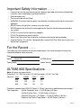
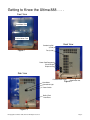
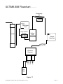
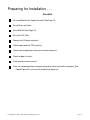
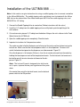
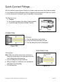
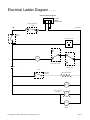
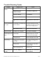
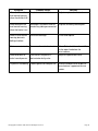
ULTIMA 888
™
Installation
Manual
For models produced after September 1, 1998
© Copyright Pure Water 1995, Rev 4/07 All Rights Reserved.
TABLE OF CONTENTS
Important Safety Information ........................................................................................3
For the Record ............................................................................................................3
ULTIMA 888 Specifications .........................................................................................3
Operating Parameters ................................................................................................4
Suitable Location for Installation ..................................................................................4
Getting to Know:
The Ultima 888 .................................................................................................5
The Cooler (Dispenser) ....................................................................................6
The MiniSoft .....................................................................................................8
How the ULTIMA 888 Works ........................................................................................9
Ultima 888 Flowchart.................................................................................................10
Preparing for Installation ............................................................................................ 11
Installation of the Ultima 888 ......................................................................................14
Ready for Operation ..................................................................................................15
Quick-Connect Fittings ..............................................................................................16
Ladder Diagram .......................................................................................................17
Trouble-Shooting Guide ............................................................................................18
© Copyright Pure Water 1995, Rev 4/07 All Rights Reserved.
Page 2
Important Safety Information . . . .
•
•
•
•
•
•
•
•
•
•
If you are not sure that your electrical outlet is properly grounded or that the circuit protection
is correct, have it checked by a qualified electrician.
Operate indoors only.
The area must be well ventilated.
WARNING: Disconnect from the power source before assembling, adjusting or servicing this
appliance.
NEVER immerse the distiller in water or any other liquid.
NEVER operate the distiller with a damaged cord or allow the cord to become exposed to
hot surfaces.
DO NOT use an extension cord or any adapters.
DO NOT let children play with the distiller.
Wait at least 30 minutes after the distiller is off before draining the boiling chamber.
Important Notice: This distiller is designed to be used only with Pure Water accessories and
replacement components.
For the Record . . . .
The model and serial number are found on the back panel. You should record all the necessary
information below for future reference.
Date:
Model:
Ultima 888
Cooler Model:
ULTIMA Serial #:
Cooler Serial #:
ULTIMA 888 Specifications . . . .
Note: All figures are approximate.
Dimensions: 14" (35.5 cm) wide x 16" (40.6 cm) deep x 18" (45.7 cm) high
Electrical: watts
voltage
cycles
amps
920
100
50
9.0
920
120
60
7.7
920
240
50
3.8
Production: Approximately 0.33 US Gallons (1.25 liters) per hour at specified operation voltages.
Tank Capacities:
Distiller Feedwater Tank— 2.5 US Gallons (9.5 liters)
Distiller Distillate Tank — 2.5 US Gallons (9.5 liters)
Dispenser Reservoir — 2.5 Room, 1.7 Cold US Gallons (19 liters)
Dispenser Hot Tank (3 Temp Model — 0.5 US Gallons (3.8 liters)
© Copyright Pure Water 1995, Rev 4/07 All Rights Reserved.
Page 3
Operating Parameters . . . .
The ULTIMA 888 unit has been designed to function within specific environmental parameters.
Operation outside of these parameters will nullify any design or manufacturing warranties.
•
Feedwater Requirements (for automatic operation):
a. Treated municipal drinking water. If suspended solids are present, a sediment filter
must be used before the mini-softener.
b. Minimum pressure is 20 PSI.
c. Maximum pressure is 100 PSI.
•
Ambient air/surface temperatures operating range is 50°-90° F (10°-32° C).
•
The ULTIMA 888 is not designed for the outdoor environment nor exposure to direct sunlight.
Suitable Location for Installation . . . .
The location where the ULTIMA 888 is placed in an office or home is very important. Several
factors must be considered:
1. Plumbing. When possible, the unit should be placed near plumbing lines, we recommend all
units should be plumbed in, if possible, to provide the most convenience for the customer.
2. Warm Air/Noise. The ULTIMA 888 system produces two by-products when operating — warm
air, and some low-level noise. When possible, the system should be located away from desks
or work stations. However, the unit may be equipped with an optional timer to control the
operation schedule of the system. With the timer, the unit may be set to operate during nonoffice hours or at night.
Note: This will be true only for small offices. Where a large number of people are served by
one unit, the unit may need to be operated on demand and without the timer being engaged.
3. Environmental-Vandalism. In applications where vandalism may be a problem, do not place
the unit in an uncontrolled or hostile environment. However, the following precautions may be
taken to prevent any misfortune.
•
Utilize a lock-in cap. Two holes may be drilled into the top cap through which plastic
pins are inserted to prevent unwanted cap removal.
•
Place lock-in protectors on fittings to prevent unwanted disconnection of tubing.
•
Use torx-type bolts on dispenser attachment brackets.
© Copyright Pure Water 1995, Rev 4/07 All Rights Reserved.
Page 4
Getting to Know the Ultima 888 . . . .
Front View
Feed Water Tank
Distilled Water Tank
Back View
Condensing Coil
(inside)
Figure 1
Fan (inside)
Power Cord Receptacle
Circuit Breaker
Dispenser Plug
Side View
Distilled Water Outlet
Hour Meter
Feed Water Inlet
Figure 2
Operational Light
Power Switch
Boiling Tank
Drain Valve
Figure 3
© Copyright Pure Water 1995, Rev 4/07 All Rights Reserved.
Page 5
Getting to Know the Cooler . . . .
Overflow Tray
Figure 4
CAUTION: If you have tilted or laid the cooler
down, let it stand 24 hours in the upright position before turning any power on. Otherwise
damage can be caused to the cooling system.
The coolers that are used with the Ultima 888
are a uniques design. Since there is no 5 gallon
bottle with this system, we have chosen to use a
cooler that has a reservoir with a 5 gallon capacity inside the cooler itself. Both the 2 temperature and the 3 temperature models have a 5
gallon reservoir. The 3 temperature model also
has an internal reservoir for hot water storage as
well.
The hot water tank is located at a lower point on
the cooler than the hot tank faucet. This means
that once the hot tank is filled with water, then it
will always have water in the tank. There are 2
very important points to remember about the hot
tank:
1. Turn the hot tank switch off until the 5 gallon
reservoir is filled, and all of the air in the tank
has been released by opening the hot tank
until water flows.
Hot, Cook and
Cold Model
(3 Temp)
Ho
t Te
mp
era
Ro
tur
om
Tem e
per
Co
atu
ld T
re
em
per
atu
re
Ro
om
Tem
per
atu
re
Co
ld T
em
per
atu
re
Cook and Cold
Model (2 Temp)
Overflow Tray
Removable Panel
Figure 5
2. If you are storing coolers that have had
water in them, or could potentially freeze,
drain all of the water out of the cooler. This
must include draining water from the hot
tank with the hot tank drain located on the
back of the cooler.
Hot Tank Switch
Figure 6
Child-Proof Hot Facuet
(Sqeeze together and pull down for flow)
Figure 7
Hot Tank
Drain (on back)
© Copyright Pure Water 1995, Rev 4/07 All Rights Reserved.
Figure 8
Page 6
Getting to Know the Cooler . . . .
Reservoir Top
Distilled Water Inlet (1/4")
Air Filter
The internal components of
the cooler are designed to be
removed very easily. This
allows for sterilization and/or
replacement very userfriendly. The main compont
that you will have to deal with
is the reservior.
2 Temp Assembly
Figure 9
Double-Floats
Water from the Ultima 888 will pass
through the post filter and enter the
reservoir through a 1/4" fitting on the
top of the reservior. This fitting is
connected to a double-float assembly. A double float is used to ensure
long term reliability in the cooler.
Figure 11
3 Temp Assembly
Figure 10
If you open the reservoir you will notice a blue baffle at about the
mid-tank level. Water for the room temperature and hot tanks will
be drawn from above the baffle, and the water below the baffle
will be chilled for the cold temperature faucet.
Below the baffle
Plug Hot
Tank Tube
Figure 12
Temperature Baffle
Hot Temperature Inlet
Figure 13
Room Temperature Inlet
Figure 14
© Copyright Pure Water 1995, Rev 4/07 All Rights Reserved.
Page 7
Getting to Know the Minisoft . . . .
The mini-softener is a small water conditioner which utilizes the same cationic exchange resin as
do larger residential and commercial water softeners.
Most water supplies contain calcium and magnesium ions that are caused by water contacting
limestone in the ground. Calcium and magnesium are often referred to as the hardness minerals.
When hard water is heated, these minerals combine with anions and precipitate from the solution
forming scale. This scale increases the maintenance and decreases the life of your product and
thus, the mini-softener is used to eliminate this scale.
Your mini-softener consists of special resin beads which attract certain ions from the water. When
new, the resin in the mini-softener has sodium ions on it. As hard water flows through the exchange
resin, the calcium and magnesium ions are captured by the resin, while sodium ions are released.
Thus, calcium and magnesium ions are exchanged for sodium ions. (Two sodium ions per one
Calcium or Magnesium ion.)
When there is no more room on the resin beads to attract calcium and magnesium, the resin will
become exhausted and will need to be recharged. This is achieved by passing a highly-concentrated salt solution through the resin. Whole-house water softeners have automated controls which
regularly rinse the resin with a concentrated brine.
Because of the relatively small volume of water that passes through the ULTIMA unit, the minisoftener can last for many months before it needs to be recharged. It has been designed to be
replaced in the field and returned to the dealer for servicing. This makes it simple and inexpensive. It can be recharged and returned to service.
Ion exchange resins should not be allowed to dry out. Hence, new mini-softeners come with small
plugs in the inlet and outlet. If a mini-softener is to be exchanged, it is a good idea to loop a length
of tubing from the inlet to the outlet. This keeps the resin wet and reduces spillage of water.
To calculate the number of gallons that can pass through the Mini-Softener use the following calculation:
2800 Grains Capacity (of the minisoft)
DIVIDED BY
Number of Grains per gallon in the water
EQUALS
Total number of gallons that the minisoft can soften before regeneration
© Copyright Pure Water 1995, Rev 4/07 All Rights Reserved.
Page 8
How the ULTIMA 888 Works . . . .
Raw water moves through a mini-softener
4
(1), which removes hardness scale and
2
minimizes maintenance of the boiling
5
chamber, and is then stored in the Feed
Water Tank (2).
3
6
Water is drawn from the Feed Water Tank
into the Level Control Housing attached to
7
the Boiling Tank. The level control housing
maintains the proper level of water in the
8
boiling tank. During the process of distillation, the water is boiled in the boiling tank
(3). Steam rises and passes through a
9
stainless steel condensing coil (4). A fan
(5) cools the steam in the condensing coil
and turns it to high-purity water, free of
virtually all contaminants. The distilled
drinking water is stored in the Distilled
Water Tank (6).
1
The water then passes through a post filter
(7); either a carbon filter to enhance the
taste and remove any Volatile Organic or
Inorganic Compounds.
Upon demand, the distilled water flows
from the Distilled Water Tank into the
Figure 15
dispenser (8), which has an additional 19
liter (5 gallon) storage system. Hot, cold,
Figure 16
and room temperature water can be
dispensed at your convenience through
three separate faucets (9).
© Copyright Pure Water 1995, Rev 4/07 All Rights Reserved.
Page 9
ULTIMA 888 Flowchart . . . .
Condensing
Coil
Fan
Raw Water
Tank
Minisoft
Level Control
Housing
Boiling
Tank
Distilled
WaterTank
ter
VOC Fil
Dispenser
Reservoir
H
R
C
Hot
Tank
Figure 17
© Copyright Pure Water 1995, Rev 4/07 All Rights Reserved.
Page 10
Preparing for Installation . . .
Checklist
Rinse and Sterilize the Cooler Reservoir (See Page 12).
Set-up Ultima on Cooler.
Rinse MiniSoft (See Page 13).
Rinse the VOC Filter
Operate Unit (24 hours minimum).
Check output water for TDS and taste.
Check water temperatures from each faucet on dispenser.
Check for debris in tanks.
Clean exterior or tanks and unit.
Drain unit completely before transporting (top tank, lower tank, boiler, and cooler) See
Page 6 Figure #7 if you have a 3 temperature dispenser.
© Copyright Pure Water 1995, Rev 4/07 All Rights Reserved.
Page 11
Preparing for Installation . . .
Sterilizing the Dispenser
Note: The reservoir of the Aqua Bar dispenser must be
cleaned and disinfected prior to delivery.
2 Temperature
1. Remove the Reservoir from the cooler by pulling up. (Figure
18)
2. Plug Hot tank tube (if you are using 3 temperature model)
3. Remove top blue Cover.
4. Mix a solution of one teaspoon of bleach to two gallons of
water. Add to the tank. Note: Rubber gloves should be worn
during the procedure.
5. Wash the inside of the reservoir and the baffle with the
solution. Note: Do not allow the sanitizing solution to remain
in the tank more than five minutes.
6. Drain the solution through the cold water faucet.
Figure 18
3 Temperature
7. Rinse the reservoir with two gallons of purified water and
drain the water through the cold water faucet.
8. Remove the plug from the hot tank tube.
9. Completely fill the reservoir with purified water. Drain the
water from the reservoir through all faucets.
10. Ensure all tanks are thoroughly drained.
Plug Hot
Tank Tube
11. (3 Temp Models) Put sterilizing solution into the hot tank,
then drain out at the hot tank drain.
12. Clean the baffle with a solution of bleach and water. Rinse
thoroughly with purified water and reinstall in the dispenser.
© Copyright Pure Water 1995, Rev 4/07 All Rights Reserved.
Figure 19
Page 12
Preparing for Installation . . .
Preparing the MiniSoft
The mini-softener may contain fines or particles of resin which are small enough to pass through
the mini-softener and be carried to the boiling tank in the feed water. These are a result of shipping.
We recommend you rinse the fines from the softener
prior to installing the ULTIMA unit at the customers
location. To rinse the fines:
Inlet from
Raw Water
Source
1. Remove the mini-softener from the packaging
carton and inspect the unit and fittings for possible
shipping damage. Remove the small plugs from
the inlet and outlet fittings. To remove the plugs
from the fittings, follow the instructions on page 6.
2. Cut and connect a piece of 1/4” tubing from the
Feed Water to the top of the mini-softener.
Rinse fines
down a
Drain
3. Cut and connect a piece of 1/4” tubing from the
base of the mini-softener to the drain.
4. Allow approximately 8 liters (2 gallons) to flow out
of the tubing to a drain until it is clean and free of
resin fines.
Figure 20
5. Remove the piece of tubing from the top of the
mini-softener. Connect tubing from the inlet to the outlet on the minisoft (This will prevent the
minisoft from drying out which can cause damage to the resin). The softener is now ready to
be transported to the installation site.
Preparing the VOC Post Filter
Included with each ULTIMA unit is a V.O.C. post filter. The post filter serves to improve the taste of
the water, and remove any stray volatile contaminants from distillation.
1. Remove the post filter from the package.
2. Connect the speedfit elbow with a piece of 1/4” tubing to a distilled water source.
3. Run Distilled water through the filter until there is a clear stream of water.
© Copyright Pure Water 1995, Rev 4/07 All Rights Reserved.
Page 13
Installation of the ULTIMA 888 . . .
Note: In this section, we give instructions for using a saddle tapping valve to connect a waterline
to the Ultima 888 distiller. The saddle-tapping valve and tubing is not included with the Ultima
888, but can be ordered from Pure Water under part #9514 for the saddle-tapping valve, and
9526-25R for 1/4" tubing.
1. Connect the Saddle Tapping Valve to a waterline (Follow instructions with the valve.)
2. Install the 1/4” tubing from the saddle tapping valve or utility hook-up to the top fitting of the
mini-softener.
3. Cut and connect a piece of 1/4” tubing from the bottom fitting on the mini-softener to the Feed
Water Inlet on the ULTIMA unit.
4. Open the saddle tapping valve completely. Check for leaks.
5. Important instructions for 3 temperature coolers:
The cooler must be full of distilled water and all air out of the tanks and lines before turning the
hot tank on. Make sure that the hot tank power switch is in the off position. To access this
switch the bottom front panel on the dispenser must be removed. Figure 22.
Once the dispenser is full of water (24 hours), then the air can be released from the cooler by
holding the faucet open on each of the temperature faucets. For the hot tank, the faucet must
be held for up to 2 minutes for water to flow out of the dispenser. Figure 21.
Note: The hot tank Faucet is designed to be child-resistent, to open, squeeze the two parts together and then push
down.
Once water flows out of the hot tank faucet, turn the hot tank
power switch to the ON position.
Hot Tank
ON/OFF Switch
Figure 21
© Copyright Pure Water 1995, Rev 4/07 All Rights Reserved.
Figure 22
Page 14
Ready for Operation . . .
When the unit is ready for operation, you can either use the optional timer control or the unit in the
on demand mode.
Before operating, ensure the following:
• Water supply is on.
• Saddle tapping valve or utility hook-up is open.
• No leaking at the waterline or fittings.
• Dispenser is plugged into the ULTIMA unit.
• Unit is plugged into a power source.
• Registration card is completed and returned to Pure & Secure LLC.
• There are no air blockages in the tubing.
Note: Use wire ties to tidy up the cords and tubing at the back of the unit.
Note: The Hot Water Tank Drain Valve is located at the lower right on the rear of the unit. If you
need to drain the hot water tank entirely, simply open the valve by turning it counterclockwise.
After the water has drained, be sure to close the valve.
© Copyright Pure Water 1995, Rev 4/07 All Rights Reserved.
Page 15
Quick-Connect Fittings. . . .
We have selected a special type of fitting that is a rapid, simple and secure way to connect tubing.
It is very important that the tube being used has a squarely cut end, and that the tube cross section
is circular and not oval. Cutting with a very sharp blade is recommended.
The fitting consists of:
a. The body.
b. An o-ring to seal against the tubing. (single or double)
c. A collet that grips the tubing and holds it in place.
O-ring(s)
Collet
Body
Figure 23A
CONNECTING
To Connect:
a. Push the tubing firmly into the fitting.
b. Pull to confirm that it has been secured.
c. Push the tubing firmly into the fitting again.
Figure 23B
DISCONNECTING
To Disconnect:
Note: Make sure that the water to the connection is
turned off and that there is no water pressure in the
line or fitting before disconnecting.
a. Push the tubing firmly into the connector.
b. With your fingers or suitable tool, push and hold the
collet against the fitting body.
c. Pull the tubing free.
© Copyright Pure Water 1995, Rev 4/07 All Rights Reserved.
push in on grey
collet and pull on
tubing
Figure 23C
Page 16
Electrical Ladder Diagram . . . .
Ultima Ladder Diagram
120 VOLT
P OWE R
C ONNE C T ION
C IR C UIT B R E AK E R
15 AMP
HOT
NE UT R AL
ON/OF F
S WIT C H
C OOLE R OUT LE T
NO
NO
NC
COM
C .R . 1
NC
COM
DIS T ILLE D WAT E R
HIG H LE VE L F LOAT
R AW WAT E R LOW
LE VE L F LOAT
C .R . 1
RESET
OVE R HE AT
S WIT C H
HE AT ING E LE ME NT
F AN
MOT OR
ON/OF F S WIT C H
ON LIG HT
G
HM
HOUR
ME T E R
© Copyright Pure Water 1995, Rev 4/07 All Rights Reserved.
Page 17
Trouble Shooting Guide
Symptom
Unit does not
operate.
Probable Cause
Unit not plugged in.
Solution
Plug unit into power source.
Power failure, circuit
breaker, fuse blown
Reset breaker. Replace fuse.
No water in top tank
Fill the top tank.
Lower tank is full tank.
Drain some water from lower tank.
Timer control has turned the unit
off.
Turn knob one click counterclock
wise.
Air blockage in the feedline from
the mini-softener.
Disconnect tubing from the level
control housing, lower to restart the
flow. Reinsert tubing into unit.
Heating element failure.
Replace the heating element
Top tank overflows.
Feed pressure is too great.
Install a pressure regulator.
Saddle tapping valve
leaks.
Loose clamp.
Tighten clamp screws. DO NOT
crush the source water tubing.
Tubing deformed.
Replace damaged area of tube.
Tubing not pushed completely
into fitting.
Push tubing into fitting past the
o-ring seal.
Defective tube.
Cut damaged area from tube or
replace the tube.
Worn or damaged o-ring.
Replace o-ring.
Post filter is depleted.
Replace post filter. Drain distilled
water completely.
Unit runs, but exhaust
air is cold.
Leak at fitting.
Water has bad taste
or smell.
© Copyright Pure Water 1995, Rev 4/07 All Rights Reserved.
Page 18
Symptom
Water overflows the
level control housing
when the distiller if off.
Probable Cause
Float valve stuck or failed.
Solution
Adjust or replace the float valve.
Water overflows the
level control housing
when the heater is on.
Blockage in the boiler outlet or
condensing tubing or connector.
Replace or modify blocked part.
Water in level control
housing, but not in
boiling chamber.
Restrictor blockage.
Clean and replace.
Dirt in raw water tank.
Excess sediment in feed water.
Water overflows or
leaks from dispenser.
Float valve in dispenser is
obstructed or faulty valve.
Clean Tank. Install a sediment filter
in the water line before the
mini-softener.
Adjust or replace float valve.
Dispenser not cooling. Coolant gone from compressor.
© Copyright Pure Water 1995, Rev 4/07 All Rights Reserved.
Remove and deliver to dispenser
manufacturer's approved service
center.
Page 19
© Copyright Pure Water 1995, Rev 4/07 All Rights Reserved.