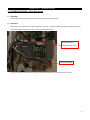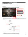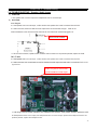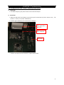
1
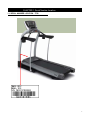
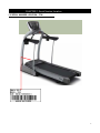
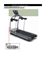
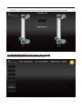
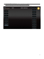
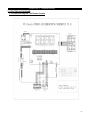
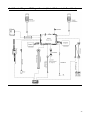
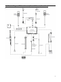
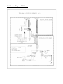
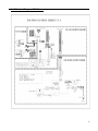
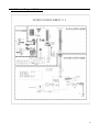
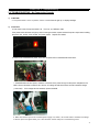
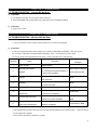
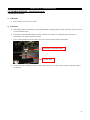
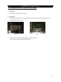
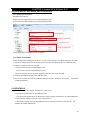
Vision Fitness TF20-TF40-T40
Frame with Classic / Elegant / Touch
Console Service Manual
1
TABLE OF CONTENTS
CHAPTER 1: SERIAL NUMBER LOCATION
1.1
Serial Number Location - TF20 Frame……………………………………………..……………….…..3
1.2
Serial Number Location - TF40 Frame…………………………………………………………….……4
1.3
Serial Number Location - T40 Frame……………………………………………………………………5
1.4
Serial Number Location – Classic / Elegant / Touch Console…..……………………………...…….6
CHAPTER 2: ENGINEERING MODE
2.1
Engineering Mode - Classic Console………………………… ………………………………..….……..7
2.2
Engineering Mode Overview - Classic Console………………………………………………………….8
2.3
Engineering Mode - Elegant Console………………………… ……………………………..…………..9
2.4
Engineering Mode Overview - Elegant Console………………………………………….……………..10
2.5
Engineering Mode - Touch Console………………………………………………………………..…….16
2.4
Engineering Mode Overview - Touch Console………………………………………………….....……17
CHAPTER 3: TROUBLESHOOTING
3.1
Electrical Diagrams…………………………………..……………………………………….…….….….25
3.2
Troubleshooting - No Power to the Console………………………………………………..……….....31
3.3
Troubleshooting - System Will Not Start……..………………………………………….……..……….33
3.4
Troubleshooting - Machine Will Not Start…….…………………………….………..….……….....…..33
3.5
Troubleshooting - Touch Panel Issues..………………………………………………….…….....…….34
3.6
Troubleshooting - Heart Rate Issues…………………………………………………….……………...35
3.7
Troubleshooting - iPod Issues……………………………………………………………………………36
3.8
Troubleshooting – Speaker / Audio Issues…….………………………………………………………..37
3.9
Troubleshooting – Radio Frequency (RF) Board Issues………………….…………………………...38
3.10 Troubleshooting – Virtual Active (VA) Issues…………………………………………………………...39
CHAPTER 4: UPDATE OS&SOFTWARE&IO
4.1 Update OS & Software……………………………………………………………………………..……..40
4.2 Update IO…………………………………………………………………………………………………...40
2
CHAPTER 1: Serial Number Location
1
1.1 SERIAL NUMBER LOCATION - TF20
3
CHAPTER 1: Serial Number Location
1
1.2 SERIAL NUMBER LOCATION - TF40
4
CHAPTER 1: Serial Number Location
1
1.3 SERIAL NUMBER LOCATION - T40
5
1
CHAPTER 1: Serial Number Location
1.4 SERIAL NUMBER LOCATION - Touch / Elegant / Classic Console
Touch
Elegant
Classic
6
CHAPTER 2: Engineering Mode
2.1 ENGINEERING MODE - Classic Console
1) To enter Engineering Mode, press & hold the INCLINE UP “▲” and SPEED DOWN “▼” keys at the same time for 3-5
seconds until Engineering Menu appears on the display.
2) Use the INCLINE and SPEED UP and DOWN keys to select a parameter.
3) Press ENTER to enter a parameter setting.
4) Use the INCLINE and SPEED UP and DOWN keys to change the parameter.
5) Press the START key to save the change to the parameter.
6) Press and hold the STOP key to exit Engineering Mode and return to normal operation.
7
CHAPTER 2: Engineering Mode
2.2 ENGINEERING MODE OVERVIEW - Classic Console
MODE
ENG 0
FUNCTION
Display Test
DESCRIPTION
Start Key – LCD/LED on
Stop Key – LCD/LED off
Any Other Key - Will show on the display window.
Hold the STOP key for 3 seconds to return to the Engineering Menu.
ENG 1
Hardware Test
Motor, Incline Motor, & Heart Rate Test.
ENG 2
Auto Calibration
If you have a digital MCB, Auto Calibration is not necessary. Press the
START key, the words “NO FUNCTION” will scroll on the screen.
ENG 3
Switch Function
- Use the INCLINE or SPEED UP and DOWN keys to switch Energy Save
Mode (ESM) off or on (shown in the SPEED window).
- Use the START key to select unit (Miles or Kilometers) (shown in the
INCLINE window).
Press the ENTER key to enter the Language setting:
- Use the INCLINE or SPEED UP and DOWN keys to select the languages
(English, German, Dutch, French will scroll on the middle window).
ENG 4
Information
Accumulated Time, Distance, and Aged
Press and hold the START key for 5 seconds to clear all data.
Remarks: Unit of Time is Hour.
Unit of Distance is KM or Mile.
Unit of Aged is Minute. (factory only setting)
ENG 5
Set Machine
Set the Machine Type – Options include TF20, T40, and TF40.
Set the Distance Type – Options are Mile or Kilometer.
Press ENTER to scroll to the other settings.
SECOND LEVEL
ENG 8
Software Version
To Get to ENG 8 - Enter into ENG 3, then press and hold the SPEED
DOWN and INCLINE UP key at the same time for 3-5 seconds.
Press ENTER at P0 - Software version.
Press ENTER at P1 - Select speed up rate (normal or quick).
Press ENTER at P3 - Hold the START key to clear all data.
※ Press the “START” key to save any changes.
8
CHAPTER 2: Engineering Mode
2.3 ENGINEERING MODE - Elegant Console
1) To enter Engineering Mode, press & hold the INCLINE UP “▲” and SPEED DOWN “▼” keys at the same time for 3-5
seconds until Engineering Menu appears on the display.
2) The Engineering Mode parameter list will be displayed on the screen.
3) Press the ATM style key on either side of the screen to enter the appropriate screen settings.
4) Set all the information using the ATM style keys.
5) Press and hold the “STOP” key to exit Engineering Mode.
9
CHAPTER 2: Engineering Mode
2.4 ENGINEERING MODE OVERVIEW - Elegant Console
2.4.1 ENGINEERING MODE (Elegant Console) – About
The Engineering Mode displays the basic parameters of the console, such as Model Type, Software Version, MCB Version,
etc…
Use the ATM style keys located on both sides of the screen to enter into the parameter.
NOTE:Navigation of the other Engineering Mode screens is the same, instructions are not repeated.
Arrows point directly to the
corresponding ATM style key
Engineer Mode
Function & Default
Descriptions
Modified
- About
Accumulated
Accumulated Distance
Data
Total distance displayed in native
Cannot be modified
units (miles or kilometers), not
editable
Main Board
Accumulated Time
Total time, not editable
Cannot be modified
UI Software Version
Application version, not editable
Cannot be modified
IO Version
Sub UCB software version, not editable
Cannot be modified
OS Version
Operation System Version, not editable
Cannot be modified
MCB Type
The frame MCB type, for example:
Cannot be modified
Information
MCB
Information
2.75HP digital MCB
MCB Software Version
MCB Software Version
Cannot be modified
10
2.4.2 ENGINEERING MODE (Elegant Console) - Settings Tab
The Settings Tab includes options for setting Machine Type, Model Type, Energy Saver, First Boot, and Program Speed.
Use UP and DOWN to choose
Press the key next to "Continue" to enter the next page of settings. Set these settings the same way as Machine Type.
NOTE: After changing a setting on any page, select "Finished" to complete the setup, the other items will keep the
default settings, press "Restore" to restore to the factory settings.
2.4.3 ENGINEERING MODE (Elegant Console) - Test Tab
The Test Tab includes various tests of the functions of the unit.
11
Display test – This tab tests the color settings of the console.
The console will cycle between red, green, and blue when
the Continue key is selected.
Hardware Test – This tab allows a service technician to test the RPM sensor and / or the incline motor.
Changing a
setting should cause the belt and / or the incline motor to operate.
12
Key Test – Press any key to test the function.
Audio Test – When this test is chosen, the console chime should sound.
2.4.4 ENGINEERING MODE (Elegant Console) – Default Tab
The Default Tab includes options for setting Max Workout Time, Default Workout Time, Warm-up Time, Cool Down Time,
and Pause Time.
Press the key next to "Continue" to enter the next page of defaults. Set these defaults using the arrow keys.
NOTE:
After changing a setting on any page, select "Finished" to complete the setup, the other items will keep the default settings,
select "Restore" to restore to the factory settings.
13
2.4.5 ENGINEERING MODE (Elegant Console) - Error Log Tab
The console will automatically show an error code history for the unit.
2.4.6 ENGINEERING MODE (Elegant Console) – Region Tab
The Region Tab includes settings for Month, Day, Year, Time (hour / minute), Language, Country, and Units (miles /
kilometers).
14
Press the key next to "Continue" to enter the next page of region settings. Set these region settings using the arrow keys.
NOTE: After changing a region setting on any page, select "Finished" to complete the setup, the other items will keep the
default region settings, select "Restore" to restore to the factory settings.
2.4.7 ENGINEERING MODE (Elegant Console) - Service Log Tab
The Service Log Tab allows the club / service provider to keep track of the service history.
15
CHAPTER 2: Engineering Mode
2.5 ENGINEERING MODE - Touch Console
1) To enter Engineering Mode, touch the four corners of the touch screen from 1-4 as shown below.
1
2
4
3
2) An Engineering Mode parameter list will be displayed on the screen.
3) Select the parameter by touching the parameter list.
4) Set all information using the Touch panel.
5) Press the Home key to save the change to the parameter and exit the Engineering Mode.
16
CHAPTER 2: Engineering Mode
2.6 ENGINEERING MODE OVERVIEW - Touch Console
2.6.1 ENGINEERING MODE (Touch Console) - About
The About Tab shows the basic parameters of the console, such as Model Type, Software Version, MCB Version etc…
NOTE: Press the Home key at any time to return to normal operation.
About
Setting
Default
Region
Test
Error log
Service Log
Engineer Mode
Function & Default
Descriptions
Modified
- About
Accumulated
Accumulated Distance
Data
Total distance displayed in native
Cannot be modified
units (miles or kilometers), not
editable
Main Board
Accumulated Time
Total time, not editable
Cannot be modified
UI Software Version
Application version, not editable
Cannot be modified
IO version
Sub UCB software version, not editable
Cannot be modified
OS Version
Operation system version, not editable
Cannot be modified
MCB Type
The frame MCB type, for example:
Cannot be modified
Information
MCB
Information
2.75HP digital MCB
MCB Software Version
MCB Software Version
Cannot be modified
17
2.6.2 ENGINEERING MODE (Touch Console) - Settings Tab
The Settings Tab used to set the Machine Type, Model and if the Energy Saver is turned on.
Setting: Pressing the
will automatically bring up the corresponding select block, according to the
frame type to select the appropriate machine, TREADMILL, ELLIPTICAL or BIKE.
automatically bring up
the corresponding
select block
Use the same procedure as Machine Type to set the Model Type, Energy Saver, First Boot and Program Speed.
2.6.3 ENGINEERING MODE (Touch Console) – Default Tab
The Default Tab displays the default information of the console, such as Workout Time, Weight, Age etc…
Selecting the data that needs to be set will bring up a slider to adjust the corresponding information.
Refer to the figure
below:
18
Touching here will bring up a slider
Touch this
arrow to
adjust the
information
Restore to the factory settings
Engineer
Function & Default
Descriptions
Modified
Mode - Default
Time
Maximum Workout Time
This option enables you to set the
Maximum: 99 Minutes
Default: 99 minutes
maximum workout duration limits
Minimum: 5 Minutes
Default Workout Time
This option enables you to set user
Maximum: 99 Minutes
Default: 20 minutes
default workout time
Minimum: 5 Minutes
Pause Time
This option enables you to set workout
Maximum: 99 Minutes
Default: 5 minutes
pause time, the console will reset when this
Minimum: 5 Minutes
time expires
Age
Weight
Gender
Volume
Warm Up Time
This option enables you to set user’s
Maximum: 99 Minutes
Default: 2 minutes
warm up time
Minimum: 5 Minutes
Cool Down Time
This option enables you to set users Cool
Maximum: 99 Minutes
Default: 5 minutes
Down Time after a workout
Minimum: 5 Minutes
Default Age
This option enables you to set the user’s
Maximum: 99
Default: 30
default age if not selected during setup
Minimum: 13
Default Weight
This option enables you to set user’s
Maximum: 375LBS
Default:150LBS
default weight if not selected during setup
Minimum: 55LBS
Default Gender
This option enables you to set user’s
Male/Female
Default: Male
gender if not selected during setup
Default Volume
This option enables you to set speaker or
Maximum: 20
Default: 20
earphone volume
Minimum: 0
19
Heart Rate
Default Target Heart Rate
This option enables you to set target
Maximum:100%
Default: 85%
heart rate for some heart rate programs
Minimum: 0
Brightness
This option enables you to set the LCD
Maximum:100%
Default: 75%
panel brightness level
Minimum: 0
Virtual Active
VA Message
This option enables you to set the VA,
On/off
Message
Default: on
user can choose the VA message
Brightness
displayed on the screen or not
Virtual Active
VA Music
This option enables you to set the VA,
Music
Default: on
user can choose the VA music played or
On/off
not
Use the same operation as Max Workout Time to adjust the other Default information.
Press "Restore" to restore to the factory settings.
2.6.4 ENGINEERING MODE (Touch Console) – Region Tab
The Region Tab is used to set Date, Time, Language, Country, and Units. Touch the item that needs to be set, the screen
will display a number keypad. Use the keypad to set the information, and press "Home" to save the information. Refer to
the figure below:
HOME ICON
Number setting keypad
20
2.6.5 ENGINEERING MODE (Touch Console) - Test Tab
The Test Tab is used to test the corresponding hardware.
Display Test
Key Test
Audio Test
Hardware Test
Display Test – Tests the reliability of the LCD and Touch panel.
Display Test - Touch panel Test
Use your finger to draw a line following the instructions on the screen.
If the test fails, selecting "continue" will bring the
user directly into the calibration screen. Refer to the figure below:
21
Key Test – Tests the functionality of the keys. Select any key on the keypad to display the definition, the function, and
the code of the key. If there is no feedback, check the keypad connection with the UCB. Select Continue to exit the
test.
Audio Test – When the Audio Test key is pressed, the console should chime.
22
Hardware Test – This tab allows a service technician to test the RPM Sensor, Incline Motor and Heart Rate
components.
Changing a setting should cause the belt, incline motor, or heart rate display to operate.
2.6.6 ENGINEERING MODE (Touch Console) - Error Log Tab
The console will automatically show an error code history for the unit.
23
2.6.7 ENGINEERING MODE (Touch Console) - Service Log Tab
The Service Log Tab allows the club / service provider to keep track of the service history.
24
CHAPTER 3: Troubleshooting
3.1 ELECTRICAL DIAGRAMS
3.1.1 Electrical Diagram –TM Classic Console
25
3.1.2 Electrical Diagram - TM Elegant Console (10inch LCD Console; No Touch Panel)
26
3.1.3 Electrical Diagram - TM Touch Console (15inch LCD Console; Touch Panel)
27
3.1.4 Electrical Diagram - TF20 Frame
28
3.1.5 Electrical Diagram - TF40 Frame
29
3.1.6 Electrical Diagram - T40 Frame
30
CHAPTER 3: Troubleshooting
3.2 TROUBLESHOOTING – No Power to the Console
1) SYMPTOM:
a. The power switch is in the on position, but the console does not light up, no display backlight.
2) SOLUTION:
a. First check to see if the power switch is lit. If it is not, try a different outlet.
If the power switch still does not light up with a known good outlet, inspect and test the power components including
the power cord, socket, circuit breaker, and power switch. Replace as needed.
b. Check to see if the MCB has power. There is a red power LED on the MCB that should be lit.
c. If the MCB does not have power, check the connection of the power wiring from the power receptacle to the
MCB. Use a multi-meter to measure AC1 & AC2, AC voltage should be the same as local’s standard voltage
(110V-240V). If AC voltage value is standard, replace the MCB.
d. Make sure that the input to the console's power supply is a 12VDC, use a multi-meter to measure the voltage
of the four pins in the figure below, pins 1 & 2 should be 12VDC and pins 7 & 8 should be ground.
31
LVDS 接口
GND
12VDC
e. If there is not 12VDC power supplied, check if the console cable is in good condition. If yes, check the output power
of the MCB (12VDC). If no output, replace the MCB
OK
UCB connection floating high
cable connection not be inserted
fully
f. If the 12VDC power supply is ok, re-confirm the connection of the LVDS* interface to the display.
Powered on, the
UCB power supply is 12VDC, confirm whether the voltage is negative as the figure shows.
g. If the power output of the LVDS interface is ok, check the LVDS wire for breakage or loose connections, if not ok,
replace the display.
h. If there is no 12VDC output from the LVDS interface, replace the console.
*
LVDS :Low-Voltage Differential Signaling, LVDS interface is LCD Panel universal interface standard
32
CHAPTER 3: Troubleshooting
3.3 TROUBLESHOOTING – System Will Not Start
1) SYMPTOM:
a. LCD displays back light, but the system does not start up.
b. The LCD backlight is lit, but the Vision Logo never clears, the LCD displays nothing.
2) SOLUTION:
a. Replace the console.
CHAPTER 3: Troubleshooting
3.4 TROUBLESHOOTING – Machine Will Not Start
1) SYMPTOM:
a. The unit has power, and a program can be started, but no control of the program.
2) SOLUTION:
a. Enter the Engineering Mode, select Settings, and confirm the MACHINE and MODEL TYPE are correct.
b. If not correct, select the correct MACHINE and MODEL TYPE,and confirm the function again.
c. If correct, please check the MCB LED blink code.
LED Blinks
1
2
Status
Works normally
Optical Encoder without
feedback
Refer to the MCB error code list below.
Description
The optical encoder is without feedback
for 3 seconds during start procedure or
1 second during workout.
The motor current is over rated for more
Overload
4
Rampage
5
The safety key fell off
The safety key fell off.
The incline motor is stuck or has
There is no signal to the MCB when the
lost efficiency
incline motor is energized.
7
8
Communication abnormal
Damaged
Works normally
3
6
Possible Components
than 4 seconds.
The motor power components damaged
or speed up too fast.
Poor contact or damage
to the optical encoder
Motor
Motor
Safety Key
Incline Motor
No or abnormal communication
Console Cable, UCB, or
between the console and MCB.
MCB
Bad connection between the
The incline motor cannot go back to
incline motor and the MCB
absolute “0” degrees.
Incline Motor or MCB
d. If the MCB and the console cable are well-connected, please update the IO software version.
Check the unit for
function again after updated.
e. If the issue is still present, replace the console.
33
CHAPTER 3: Troubleshooting
3.5 TROUBLESHOOTING – Touch Panel Issues
Touch panel issues
1) SYMPTOM:
a. Touch screen is not accurate or invalid.
2) SOLUTION:
a. If the touch screen is not accurate, or has a slight deviation, simply press the "Enter" and "Stop" keys to enter the
screen calibration mode.
b. If the touch screen calibration does not work, check the touch screen for visible damage, indentation, or
deformation. If so, replace the entire console.
c.
If not, confirm whether the touch screen, FPC wire is well-connected with the main board.
TP connect on the main board
TP FPC wire
d. If well-connected, recalibrate the touch screen (same steps as (a)), if the screen cannot be calibrated, replace
the console.
34
CHAPTER 3: Troubleshooting
3.6 TROUBLESHOOTING – Heart Rate Issues
1) SYMPTOM:
a. The console does not display the heart rate when holding the heart rate grips.
2) SOLUTION:
a. First check if the heart rate grip is well-connected, not broken / damaged. Replace the HR grip / wiring as needed.
b. Confirm whether the heart rate board is well-connected with the UCB.
Heart Rate Board
connected to the UCB
Heart Rate Board
c. If well-connected, replace the heart rate board. If heart rate still does not work, replace the console.
35
CHAPTER 3: Troubleshooting
3.7 TROUBLESHOOTING – iPod Issues
1) SYMPTOM:
a. Cannot connect the iPod prompt shown on the screen (Touch console only).
2) SOLUTION:
a. Confirm whether the iPod cable is well-connected, not broken or damaged.
iPod FPC connected to
the UCB
FFC wire connected from
the iPod board to the UCB
iPod board
iPod wire
b. Replace the iPod cable and try again. Refer to the figure below regarding the iPod cable and the iPod
board.
iPod Wire
iPod PCB Board
FFC connect wire
c. Check the FFC connect wire for damage. If any is found replace the FFC wire.
d. If the iPod still cannot connect, replace the iPod PCB board.
e. If the iPod still cannot connect after the iPod board was replaced, replace the UCB.
36
CHAPTER 3: Troubleshooting
3.8 TROUBLESHOOTING – Speaker / Audio Issues
1)
SYMPTOM:
a. The speaker has no sound output; the headphones have no sound output.
2)
SOLUTION:
3.8.1 Elegant
a. If the speaker has no sound output, confirm whether the speaker wire is well-connected with the UCB.
b. If well-connected, make sure that the audio output short-circuit terminals are tight.
Refer to the
electrical diagram to see where the audio output short-circuit terminals should be plugged in at.
Short-circuit terminal
c. If all are well-connected, update the OS, Software and IO Versions. If the problem persists, replace the UCB.
3.8.2. Touch
a. If the speaker has no sound output, confirm whether the speaker wire is well-connected with the UCB.
b. If well-connected, use a multi-meter to confirm whether the audio output terminal switch is connected. Refer to the
figure below:
If these two pins are connected the
speaker should have sound output.
c. If all wiring is well-connected, update the OS, Software and IO Versions. If the problem persists, replace the UCB.
d. If the speakers have sound output, but headphones have no sound output, replace the headphone board. If the
problem persists, replace the headphone wire.
37
CHAPTER 3: Troubleshooting
3.9 TROUBLESHOOTING –Radio Frequency Board Issues
1) SYMPTOM:
a. The Radio Frequency (RF) board cannot connect with the Passport.
2) SOLUTION:
a. Make sure that the RF and Passport connection key are functional (see Key Test in Section 2.3.5).
TM
(STOP & Incline+), EP (STOP & Resistance).
b. Confirm again whether the FFC connect wire is damaged.
FFC connected to
the UCB
FPC Connector
RF board
c. If above connections are all confirmed ok, replace the RF board.
38
CHAPTER 3: Troubleshooting
3.10 TROUBLESHOOTING – Virtual Active (VA) Issues
1) SYMPTOM:
a. Cannot play the Virtual Active (VA) files.
2) SOLUTION:
a. Confirm if the SD card is firmly seated on the UCB, if not, please re-insert the SD card and use
adhesive tape to fix it in place.
No Good
OK
b. If the SD card is inserted correctly, update the Software Versions.
c. If the VA still cannot be played, replace the UCB.
39
CHAPTER 4: Update OS & Software & IO
4.1 UPDATING OS, SOFTWARE, AND IO VERSIONS
4.1.1 Update File Description
OS Update File: NK.rom;
Elegant Console Update Software File: DeluxeGUIDeploy.CAB;
Touch Console Update Software File: PremierGUIDeploy.CAB
OS update file
Software update file
Configuration file
Sub MCU update file
* Note: update the software after the OS is updated.
4.1.2 Update OS & Software
* Note: OS files need to distinguish between 7, 10, and 15 inch displays. The OS file names are the same.
1. Choose the correct OS nk.rom file according to the LCD size, and place the file on a USB flash drive.
2. Update the software version on the USB..
- Elegant console choose “eluxeGUIDeploy.CAB”.
- Touch console choose “PremierGUIDeploy.CAB”.
* Note: The two files can not be placed together at the same time under the USB
3. Place the “updadte.config” file on the USB flash drive.
4. Start up the console, and insert the USB flash drive into the slot in the front of the console. The files will
update automatically.
4.2 UPDATING IO
1. IO Update Files: BL_130.TXT, PATCH.TXT, and IO1.TXT.
2. Place the three files above on the USB flash drive.
* The name of the update file for the Elegant and Touch consoles are the same, no need to distinguish.
3. Also place the “Update.config” file on the USB flash drive.
4. Start up the console, and insert the USB flash drive into the slot in the front of the console.
The
software will update automatically.
40