1
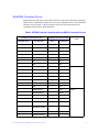
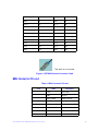
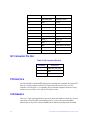
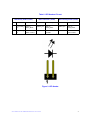
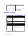
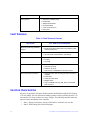
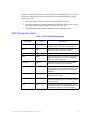
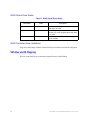
Intel® Integrated RAID Controller
RS2SG244 Hardware User’s Guide
Intel Order Number: E98815-002
DISCLAIMER
INFORMATION IN THIS DOCUMENT IS PROVIDED IN CONNECTION WITH INTEL(R)
PRODUCTS. NO LICENSE, EXPRESS OR IMPLIED, BY ESTOPPEL OR OTHERWISE, TO ANY
INTELLECTUAL PROPERTY RIGHTS IS GRANTED BY THIS DOCUMENT. EXCEPT AS
PROVIDED IN INTEL'S TERMS AND CONDITIONS OF SALE FOR SUCH PRODUCTS, INTEL
ASSUMES NO LIABILITY WHATSOEVER, AND INTEL DISCLAIMS ANY EXPRESS OR IMPLIED
WARRANTY, RELATING TO SALE AND/OR USE OF INTEL PRODUCTS INCLUDING LIABILITY
OR WARRANTIES RELATING TO FITNESS FOR A PARTICULAR PURPOSE,
MERCHANTABILITY, OR INFRINGEMENT OF ANY PATENT, COPYRIGHT OR OTHER
INTELLECTUAL PROPERTY RIGHT. Intel products are not intended for use in medical, life saving,
life sustaining applications. Intel may make changes to specifications and product descriptions at
any time, without notice.
Intel is a trademark or registered trademark of Intel Corporation or its subsidiaries in the United
States and other countries.
*Other names and brands may be claimed as the property of others.
Copyright © 2010 by Intel Corporation. Portions Copyright 2010 by LSI Corporation. All rights
reserved.
ii
Intel® RAID Controller RS2SG244 Hardware User’s Guide
Preface
This is the primary hardware guide for the Intel® RAID Controller RS2SG244, which can
be used to manage SAS and SATA disk drives. It contains installation instructions and
specifications.
For details on configuring the storage adapters, and for an overview of the software
drivers, see the Intel® RAID Software User’s Guide on the Resource CD.
Audience
This document assumes that you have some familiarity with RAID controllers/modules
and related support devices. The people who benefit from this book are:
• Engineers who are planning to use an Intel® RAID Controller RS2SG244 as a part
of their RAID system.
• Anyone installing an Intel® RAID Controller RS2SG244 in their RAID system.
Organization
This document includes the following chapters and appendices:
• Chapter 1 provides a general overview of the Intel® RAID Controller RS2SG244.
• Chapter 2 describes the procedures for installing and configuring the RAID
controller.
• Chapter 3 provides the characteristics and technical specifications for the Intel®
RAID Controller RS2SG244.
• Appendix A explains drive roaming and drive migration.
• Appendix B provides safety instructions to be observed during installation and
assembly.
• Appendix C provides regulatory and certification information.
Related Publication
The Intel® RAID Software User’s Guide is included on the Resource CD that shipped with
the RAID controller.
Intel® RAID Controller RS2SG244 Hardware User’s Guide
iii
iv
Intel® RAID Controller RS2SG244 Hardware User’s Guide
Table of Contents
Preface ........................................................................................................................ iii
Audience ............................................................................................................................... iii
Organization ......................................................................................................................... iii
Related Publication ............................................................................................................... iii
Chapter 1: Overview ................................................................................................... 1
Benefits of SAS and SATA .................................................................................................... 1
Intel® RAID Controller RS2SG244 ........................................................................................ 2
Protocol Support ............................................................................................................ 3
Operating System Support ............................................................................................ 3
Usability ......................................................................................................................... 3
Redundancy and Error Handling ................................................................................... 4
SAS/SATA Features ...................................................................................................... 6
Online Capacity Expansion and RAID Level Migration Rules ....................................... 6
Beep Codes ................................................................................................................... 6
Chapter 2: Intel® RAID Controller RS2SG244 Hardware Installation .................... 7
Requirements ........................................................................................................................ 7
Installing the RAID Controller ................................................................................................7
Configuring the RAID Controller ..........................................................................................10
Replacing a Controller .........................................................................................................10
Resolving a Config Mismatch ..............................................................................................10
Chapter 3: Intel® RAID Controller RS2SG244 Characteristics ............................ 11
Major Components ..............................................................................................................14
LSI* SAS2108 ROC .....................................................................................................14
LSI SAS2 x36 Expander ..............................................................................................14
Flash ROM ..................................................................................................................14
Boot Strap ROM (SEEPROM) .....................................................................................14
NVSRAM .....................................................................................................................14
SDRAM (Cache) ..........................................................................................................15
Diagnostic Components ..............................................................................................15
SAS/SATA Connectors ................................................................................................16
BBU Connector Pin-out ...............................................................................................19
I2C Connector Pin-Out ................................................................................................20
PCI Interface ................................................................................................................20
LED Headers ...............................................................................................................20
Serial UART Header ....................................................................................................22
Technical Specifications ......................................................................................................22
Array Performance Features ...............................................................................................23
Intel® RAID Controller RS2SG244 Hardware User’s Guide
v
Fault Tolerance ........................................................................................................... 24
Electrical Characteristics ............................................................................................. 24
Thermal and Atmospheric Characteristics .................................................................. 25
Safety Characteristics ................................................................................................. 25
Operating Certifications ............................................................................................... 25
Supported Device Technology ............................................................................................ 26
Support for Hard Disk Drive Devices .......................................................................... 26
SAS Expander Support ............................................................................................... 26
Support for Non-Hard Disk Drive Devices ................................................................... 26
Enclosure Management Support ................................................................................. 26
RAID Functionality and Features ........................................................................................ 26
Hierarchy ..................................................................................................................... 26
SAS Bus and ID Mapping ........................................................................................... 28
Appendix A: Drive Roaming and Drive Migration Install ......................................29
Drive Roaming ..................................................................................................................... 29
Drive Migration .................................................................................................................... 30
Appendix B: Installation/Assembly Safety Instructions .......................................31
English ................................................................................................................................. 33
Deutsch ............................................................................................................................... 34
Français ............................................................................................................................... 35
Español ............................................................................................................................... 37
Italiano ................................................................................................................................. 38
Appendix C: Regulatory and Certification Information .........................................41
Product Safety and EMC Compliance ................................................................................. 41
vi
Intel® RAID Controller RS2SG244 Hardware User’s Guide
List of Figures
Figure 1. Installing the Intel® RAID Controller RS2SG244........................................................ 8
Figure 2. Connecting Cable between the RAID Controller and Drives/Backplane.................... 9
Figure 3. Card Layout.............................................................................................................. 11
Figure 4. Hardware Block Diagram ......................................................................................... 13
Figure 5. Intel® RAID Smart Battery AXXRSBBU7 ................................................................. 15
Figure 6. Intel® RAID Controller RS2SG244 SAS/SATA Connectors..................................... 16
Figure 7. SFF8087 to Four-port Internal Cable with one SGPIO Connector........................... 18
Figure 8. SFF8088 External Connector Cable ........................................................................ 19
Figure 9. LED Header ............................................................................................................. 21
Figure 10. UART Connector.................................................................................................... 22
Intel® RAID Controller RS2SG244 Hardware User’s Guide
vii
viii
Intel® RAID Controller RS2SG244 Hardware User’s Guide
List of Tables
Table 1. Jumper Description ................................................................................................... 11
Table 2. SFF8087 Internal Connector with one SGPIO Connector Pin-out ............................17
Table 3. SFF8088 External Connector Pin-out .......................................................................18
Table 4. BBU Connector Pin-out .............................................................................................19
Table 5. I2C Connector Pin-Out ..............................................................................................20
Table 6. LED Headers Pin-out ................................................................................................ 21
Table 7. UART Connector Pin-out ...........................................................................................22
Table 8. Technical Specifications ............................................................................................22
Table 9. Array Performance Features .....................................................................................23
Table 10. Fault Tolerance Features ........................................................................................24
Table 11. Power Supply for the Controller ..............................................................................25
Table 12. RAID Physical Drive Status .....................................................................................27
Table 13. RAID Virtual Drive Status ........................................................................................28
Intel® RAID Controller RS2SG244 Hardware User’s Guide
ix
x
Intel® RAID Controller RS2SG244 Hardware User’s Guide
1
Overview
The Intel® RAID Controller RS2SG244 is a high port-count, high-performance intelligent
PCI Express* 2.0 compliant SAS/SATA RAID controller that offers reliability, high
performance, and fault-tolerant disk subsystem management. This is a RAID solution that
meets the internal storage needs of workgroup, department, or enterprise systems to use
with cost-effective SATA or high performance SAS media.
As a second generation PCI Express* storage controller, the Intel® RAID Controller
RS2SG244 addresses the growing demand for increased data throughput and scalability
requirements across entry level, midrange, and enterprise server platforms.
The controller controls 24 internal SAS/SATA ports through six SFF-8087 Mini SAS x4
internal connectors and 4 external SAS/SATA ports through one SFF-8088 Mini SAS x4
external connector. For more information about the use of expanders, see the ANSI SAS
Standard, version 2.0 specification.
SATA and SAS are serial, point-to-point, device interfaces that use simplified cabling,
smaller connectors, lower pin counts, and lower power requirements than parallel SCSI.
The optional Intel® RAID Smart Battery AXXRSBBU7 provides cached data protection
for the RAID controller, even during system failures.
Benefits of SAS and SATA
SAS is a serial, enterprise-level device interface that leverages the proven SCSI protocol
set. SAS is a convergence of the advantages of SATA, SCSI, and FC, and is the future
mainstay of the enterprise and high-end workstation storage markets. SAS offers a higher
bandwidth per pin than parallel SCSI and improves signal and data integrity.
The SAS interface uses the proven SCSI command set to ensure reliable data transfers,
while providing the connectivity and flexibility of point-to-point serial data transfers. The
serial transmission of SCSI commands eliminates clock skew challenges. The SAS
interface provides improved performance, simplified cabling, smaller connectors, lower
pin count, and lower power requirements than parallel SCSI.
SAS controllers leverage a common electrical and physical connection interface that is
compatible with Serial ATA technology. The SAS and SATA protocols use a thin, 7-wire
connector instead of the 68-wire SCSI cable or 40-wire ATA cable. The SAS/SATA
connector and cable are easier to manipulate, connect to smaller devices, and do not
inhibit airflow. The point-to-point SATA architecture eliminates difficulties created by the
legacy ATA master-slave architecture, while maintaining compatibility with existing ATA
firmware.
Intel® RAID Controller RS2SG244 Hardware User’s Guide
1
Intel® RAID Controller RS2SG244
The Intel® RAID Controller RS2SG244 is an intelligent PCI Express* 2.0 compliant
interface RAID adapter with an integrated LSI* SAS2108 RAID-On-Chip chipset,
providing both a SAS controller and RAID engine. With 512MB RAM built onto the
board, eight independent phys supporting 6-Gbps and 3 Gbps SAS data transfers, the
onboard LSI* SAS2 x36 expander chip, six SFF-8087 Mini SAS x4 internal connectors
and one SFF-8088 Mini SAS x4 external connector, this controller supports up to 240
enterprise-class SAS or SATA devices and 64 logical drives. The PCI Express* connector
fits into an x8 or x16 PCI Express* slot capable of performance up to 5 Gbps per lane.
The RAID controller is designed to fit the following Intel® Server Boards and Systems:
• Intel® Server Board S5520UR
•
•
•
•
•
•
•
•
•
•
•
•
•
•
•
•
•
•
•
Intel® Server Board S5500WB
Intel® Server Board S5520HC/S5520HCT/S5500HCV
Intel® Server system SC5650HCBRP
Intel® Workstation Board S5520SC
Intel® Workstation System SC5650SCWS
Intel® Server Board S5500BC
Intel® Server System SR1630BC
Intel® Server System SC5650BCDP
Intel® Server Board S3420GP
Intel® Server Board S5000PSL
Intel® Server Board S5000VSA
Intel® Server System SR1690WB
Intel® Server System SR1695WB
Intel® Server system SR2612UR
Intel® Server system SR1630GP / SR1630HGP
Intel® Server System SR1600UR
Intel® Server System SR2600UR
Intel® Server System SR2625UR
Intel® Server System SR1625UR
Note: Additional Intel® Server Boards and Systems may be supported. For the most up-to-date
list, see the Compatibility section under the link for this Intel® RAID Controller at
http://www.intel.com.
2
Intel® RAID Controller RS2SG244 Hardware User’s Guide
Protocol Support
Each port on the SAS controllers supports SAS devices, SATA II devices, or both using
SSP, SMP, STP, and SATA II as follows:
• Serial SCSI Protocol (SSP) to enable communication with other SAS devices.
• SATA II Protocol to enable communication with other SATA II devices.
• Serial Management Protocol (SMP) to share topology management information
with expanders.
• Serial Tunneling Protocol (STP) support for SATA II through expander interfaces..
Operating System Support
• Windows Server 2008* R2, Windows 7*, Windows Server 2003*, Windows Vista*,
and Windows XP*
• Red Hat* Enterprise Linux 4.0 and 5.0
• SuSE* Linux Enterprise Server 9, 10, and 11
• VMWare* ESX 4.0
• Solaris* 10
The operating systems supported may not be supported by your server board. See the
Tested operating system list for your server board at
http://www.intel.com.
To make sure the RAID controller supports your operating system, see also the Tested
Hardware and Operating System List for the Intel® RAID Controller RS2SG244.
Usability
• Small, thin cabling with serial point-to-point 6.0 Gbps data transfer rates.
•
•
•
•
•
Support for non-disk devices and mixed capacity drives.
Support for intelligent XOR RAID levels 0, 1, 5, 6, 10, 50, and 60.
Dedicated or global hot spare with auto rebuild if an array drive fails.
User defined stripe size per drive: 8, 16, 32, 64, 128, 256, 512, or 1024 KB.
Advanced array configuration and management utilities provide:
— Online Capacity Expansion (OCE) adds space to existing drive or new drive.
See Appendix A: Drive Roaming and Drive Migration Install for limitations on
OCE and RAID migration.
— Online RAID level migration (upgrade of RAID mode may require OCE)
— Drive migration
— Drive roaming
Intel® RAID Controller RS2SG244 Hardware User’s Guide
3
— No reboot necessary after expansion
• Upgradeable Flash ROM interface.
• Allows for staggered spin-up, hot-plug, and lower power consumption.
• User specified rebuild rate (percent of system resources to use from 0-100%).
Caution: Exceeding 50% rate may cause operating system errors due to waiting for
controller access.
• Background operating mode can be set for Rebuilds, Consistency Checks,
Initialization (auto restarting Consistency Check on redundant volumes), Migration,
OCE, and Patrol Read.
Redundancy and Error Handling
• SES2 enclosure management support
• SGPIO enclosure management support
• Fault indicators per drive.
• Drive coercion (auto-resizing to match existing disks).
• Auto-detection of failed drives with transparent rebuild. There must be disk activity
(I/O to the drive) for a missing drive to be marked as failed.
• Auto-resume of initialization or rebuild on reboot (the Auto Rebuild feature must be
enabled before virtual disk creation).
• Smart initialization automatically checks consistency of virtual disks if there are five
or more disks in a RAID 5 array, which optimizes performance by enabling readmodify-write mode. RAID 5 arrays of only three or four drives use Peer Read mode.
•
•
•
•
Smart Technology predicts failures of drives and electronic components.
Patrol Read checks drives and maps bad sectors.
Commands are retried at least four times.
Firmware provides best effort to recognize an error and recover if possible.
• Failures are logged from controller and drive firmware, and SMART monitor.
• Failures are logged in NVRAM, viewable from OS Event Log, Intel® RAID Web
Console 2, CIM, and LEDs.
• Multiple cache options allow configuration-specific performance optimization:
— Write-back: Faster because it does not wait for the disk but data will be lost if
power is lost.
— Write-through: Usually slower but ensures data is on the disk.
— Read Ahead: Predicts next read will be sequential and buffers this data into the
cache.
— Non Read Ahead: Always reads from the drive after determining exact location
of each read.
4
Intel® RAID Controller RS2SG244 Hardware User’s Guide
— Adaptive Read Ahead: Reads ahead and caches data only if doing sequential
reads.
— I/O setting. Determines whether read operations check the cache before reading
from disks.
✧ Cache I/O: Checks cache first, only reads disk if data is not in the cache.
✧ Direct I/O: Reads data directly from disk. (not cache)
• Redundancy through:
— Configuration stored in non-volatile RAM and on the drives (COD).
— Hot-swap support.
— Optional battery backup for cache memory.
Intel® RAID Controller RS2SG244 Hardware User’s Guide
5
SAS/SATA Features
• Eight independent PHYs internally, each supporting 6.0 Gbps SAS and SATA data
transfers.
• Provides twenty-four internal and four external ports through LSI* SAS2 x36
Expander chip.
• Scalable interface that supports up to 240 physical devices and 64 logical devices
via expanders.
• Supports Serial SCSI Protocol (SSP) to enable communication with other SAS
devices.
• Supports Serial Management Protocol (SMP) to communicate topology
management information.
• Allows addressing of multiple SATA targets through an expander if using SATA 2.0compliant hard disk drives.
• Allows multiple initiators to address a single target (in a fail-over configuration)
through an expander.
Online Capacity Expansion and RAID Level Migration Rules
•
•
•
•
Migration must occur to the same or larger capacity configuration.
Migration cannot occur if there is more than one virtual disk in a logical array.
Migration and OCE cannot be done on Spanned Arrays (RAID 10, 50, and 60).
Migrations supported are RAID 1 to RAID 0, RAID 5 to RAID 0, RAID 6 to RAID
0.
• With OCE, migrations supported are RAID 0 to RAID 1, RAID 0 to RAID 5, RAID
0 to RAID 6, RAID 1 to RAID 5, RAID 1 to RAID 6, RAID 5 to RAID 6.
Beep Codes
• Short beep (1 second on, 1 second off): Array has degraded but no data has been
lost.
• Long beep (3 seconds on, 1 second off): Array has failed and data has been lost.
• Short beep (1 second on, 3 seconds off): Using hot spare in rebuild; alarm will
continue during rebuild with a different sound at completion.
To disable the alarm, choose Disable Alarm. To enable the alarm, choose Enable Alarm.
To disable the alarm only until the next event or until next power cycle, choose
SilenceAlarm.
6
Intel® RAID Controller RS2SG244 Hardware User’s Guide
2
Intel® RAID Controller RS2SG244
Hardware Installation
Requirements
• Intel® RAID Controller RS2SG244 , with the provided standoffs
• A host system with an available x8 or x16 PCI-Express* slot
• Resource CD, which contains drivers and documentation
• SAS or SATA hard drives up to 6Gb/s speed
• Provided SAS/SATA cables (for cable requirements, see step 4 in “Installing the
RAID Controller”)
Note: Intel Corporation strongly recommends using an uninterruptible power supply (UPS).
Installing the RAID Controller
To install the RAID Controller, follow these steps:
1. Turn off the power to the system, all drives, enclosures, and system components.
Remove the power cord(s).
2. Remove the server cover. For instructions, see your server system documentation.
3. Install the RAID controller into an available server system x8 or x16 PCI-Express*
slot (see Figure 1). To locate an appropriate slot and for instructions on installing an
add-in card, see your server system documentation.
Intel® RAID Controller RS2SG244 Hardware User’s Guide
7
*
ss
re
xp
IE
PC
ot
Sl
AF003498
Figure 1. Installing the Intel® RAID Controller RS2SG244
4. Connect the provided internal and/or external cables into the adapter using the 4port combined end. Make sure the controller and cables are properly attached.
— If using an external cable, plug the cable into the connector in the end bracket.
— If using an internal cable, plug the cable into connector at the inside edge of the
adapter.
Note: To prevent throughput problems:
✧ Use the cables provided or use the shortest possible cable.
✧ Do not use cables longer than one meter.
✧ Decrease the maximum length by one foot if you are using a backplane.
✧ Do not use cross-over cables.
✧ Only connect to a SATA drive, SAS or SATA backplane, or an expander
device.
✧ Route the cables carefully.
✧ Check that the controller and cables are all properly attached.
8
Intel® RAID Controller RS2SG244 Hardware User’s Guide
AF003499
Figure 2. Connecting Cable between the RAID Controller and
Drives/Backplane
5. Install the server system cover and connect the power cords. See your server system
documentation for instructions.
Intel® RAID Controller RS2SG244 Hardware User’s Guide
9
Configuring the RAID Controller
To configure the RAID Controller, follow these steps:
1. Turn on the system power and check to make sure that the SAS/SATA devices
power up before or at the same time as the system.
2. During the boot, the following BIOS message appears to state the keys that you
need to press to enter the Intel® RAID BIOS Console 2, such as:
Press <CTRL><G> to run BIOS Console 2.
This message times out after several seconds. If you miss it, you need to restart the
system.
After you press the keys to enter the Intel® RAID BIOS Console 2 software, the
firmware takes several seconds to initialize and then display the Intel® RAID
Controller RS2SG244 number and firmware version. The numbering of the RAID
controller follows the PCI slot scanning order used by the server board.
3. See the Quick Start User’s Guide and the Software User's Guide for instructions to
configure the RAID controller and to install the operating system drivers.
Replacing a Controller
To replace the RAID controller, see your server system documentation for instructions to
remove and then install an add-in adapter.
Resolving a Config Mismatch
If the newly installed RAID controller was previously configured, a message displays
during POST, stating that there is a configuration mismatch because the configuration data
in the NVRAM differs from that in the hard drives. Use these steps to resolve the
mismatch:
1. Press <Ctrl> + <G> when prompted during boot up to access the BIOS
Configuration Utility
2. Select Configure > View/Add Configuration to see the NVRAM and drive
configurations.
3. If the drives contain the correct configuration, use configuration from the disks.
4. Press <Esc> and select YES to update the NVRAM.
5. Exit and reboot.
10
Intel® RAID Controller RS2SG244 Hardware User’s Guide
3
Intel® RAID Controller RS2SG244
Characteristics
J4A5
J4A4
J5B3
J4A1 J4A3
J2B1
Ports
0-3
J1A2
J2B2
Ports
4-7
J3B1
Ports
8-11
J4B2
Ports
12-15
J4A2 J5A2
J5A1
Ports
16-19
J1B1
J1L1
on back
J5B2
Ports
20-23
J1B3
J1B2
Ports 24-27
J1C1
J2D1
AF003500
Figure 3. Card Layout
Table 1. Jumper Description
s
Jumper
Type
Description
J1A2
Universal Asynchronous
Receiver/ Transmitter
(UART) for the
Expander
4-pin connector. Reserved for factory use.
J1B1
LED Locate and Fault
Indication header
Ports 0-3
Ports 4-7
2x8-pin connector. Connects to an LED that indicates whether a drive is in a fault condition. There
is one LED per port. When lit, each LED indicates
the corresponding drive has failed or is in the
unconfigured-bad state.
The LEDs function in a direct-attach configuration
(there are no SAS expanders). Direct attach is
defined as a maximum of one drive connected
directly to each port.
Intel® RAID Controller RS2SG244 Hardware User’s Guide
11
Jumper
12
Type
Description
J1B2
x4 SAS Ports 24-27
external connector
SFF-8088 x4 external mini SAS connector Connects the controller by cable to a SAS/ SATA
backplane or an expander.
J1B3
Premium Features
Hardware Key header
2-pin header. Enables support for selected premium features, which include Snapshot, Super
Sized Cache, FastPath, and Full Disk Encryption.
J1C1
IPMI-style I2C
connector
3-pin connector. Supports SES (SCSI enclosure
services) over I2C through an internal I2C backplane cable
J1L1
Remote Battery Backup 20-pin connector.Connects the intelligent Battery
connector (on the back- Backup Unit remotely to the RAID controller.
side of the controller)
J2B1
x4 SAS Ports 0-3 internal connector
SFF-8087 x4 internal mini SAS connector Connects the controller by cable to SAS/SATA drives.
J2B2
x4 SAS Ports 4-7 internal connector
SFF-8087 x4 internal mini SAS connector Connects the controller by cable to SAS/SATA drives.
J2D1
Standard edge card
connector
The RAID controller interfaces with the host system
though a standard edge card. This interface provides power to the board and an I2C interface
connected to the I2C bus for IPMI.
J3B1
x4 SAS Ports 8-11 inter- SFF-8087 x4 internal mini SAS connector Connal connector
nects the controller by cable to SAS/SATA drives.
J4A1
Module CPLD
1x8-pin connector. Reserved for factory use.
J4A2
Activity LED header
2-pin connector. Connects to an LED that indicates
activity on the drives connected to the controller.
J4A3
Global drive fault LED
header
2-pin connector. Connects to an LED that indicates
whether a drive is in a fault condition.
J4A4
LED Locate and Fault
Indication header
Ports 8-11
Ports 12-15
2x8-pin connector. Connects to an LED that indicates whether a drive is in a fault condition. There
is one LED per port. When lit, each LED indicates
the corresponding drive has failed or is in the
unconfigured-bad state.
The LEDs function in a direct-attach configuration
(there are no SAS expanders). Direct attach is
defined as a maximum of one drive connected
directly to each port.
J4A5
LED Locate and Fault
Indication header
Ports 16-19
Ports 20-23
2x8-pin connector. Connects to an LED that indicates whether a drive is in a fault condition. There
is one LED per port. When lit, each LED indicates
the corresponding drive has failed or is in the
unconfigured-bad state.
The LEDs function in a direct-attach configuration
(there are no SAS expanders). Direct attach is
defined as a maximum of one drive connected
directly to each port.
J4B2
x4 SAS Ports 12-15
internal connector
SFF-8087 x4 internal mini SAS connector Connects the controller by cable to SAS/SATA drives.
Intel® RAID Controller RS2SG244 Hardware User’s Guide
Jumper
Type
Description
J5A1
x4 SAS Ports 16-19
internal connector
SFF-8087 x4 internal mini SAS connector Connects the controller by cable to SAS/SATA drives.
J5A2
Write pending LED
header
2-pin connector. Connects to an LED that indicates
when the data in the cache has yet to be written to
the storage devices. Used when the write-back feature is enabled.
J5B2
x4 SAS Ports 20-23
internal connector
SFF-8087 x4 internal mini SAS connector Connects the controller by cable to SAS/SATA drives.
J5B3
Universal Asynchronous
Receiver/Transmitter
(UART) debugging
4-pin connector Reserved for factory use.
Figure 4. Hardware Block Diagram
Intel® RAID Controller RS2SG244 Hardware User’s Guide
13
Major Components
LSI* SAS2108 ROC
The LSI* SAS2108 RAID-On-Chip (ROC) is an integrated SAS and I/O controller with
an embedded Power PC* 440 core running at 800 MHz. For more information, see
http://www.lsi.com/. The LSI* SAS2108 ROC provides the following functions:
•
•
•
•
x8 PCI Express* bus operating at 6.0 Gbps serial transfer rate
•
•
•
•
•
•
Initiator and Target mode (SSP)
Spread Spectrum Clocking (SSC)
SAS/SMP/STP/SATA support
Supports SAS and SATA devices
Wide port support
T10 End-to-End Data Protection (EEDP)
Local 72-bit DDR2 SDRAM interface with ECC checking
Fusion MPT message unit
PCI Express* interface supports x8, x4, and x1 lane configurations
LSI SAS2 x36 Expander
The LSISAS2 x36 expander is a 36-port, 6.0Gb/s Serial Attached SCSI (SAS) expander
that enables the connection of up to 36 directly attached SAS or Serial ATA (SATA)
devices, and provides table routing to support connections for up to 1024 SAS addresses.
Each expander phy is individually configurable and performs SAS and SATA transfers
based on the speed of the host or target at either 6.0Gb/s, 3.0Gb/s, or 1.5Gb/s.
Flash ROM
An 8-MB CFI-compliant flash ROM is used to accommodate RAID firmware and RAID
BIOS Console 2 OpROM.
Boot Strap ROM (SEEPROM)
The serial bootstrap ROM is used to configure the LSI* SAS2108 ROC before the server
board configures the PCI Express* registers. The bootstrap ROM sets the Phase Lock
Loop (PLL) dividers, bootstrap configuration, and so on.
NVSRAM
A 32-KB NVSRAM is used to store disk and drive setup information.
14
Intel® RAID Controller RS2SG244 Hardware User’s Guide
SDRAM (Cache)
The Intel® RAID Controller RS2SG244 includes 512 MB of integrated DDR2 800 MHz
ECC SDRAM memory. This DIMM is connected directly to the memory controller
interface bus of the ROC and serves as storage for the executable code transferred from
the flash. It also serves as cache during RAID transactions. Cache mode selection takes
immediate effect while the server is online and is available on a per virtual drive basis.
The ROC memory controller provides single-bit ECC error correction with multi-bit
detection support.
The Intel® RAID Controller RS2SG244 supports Intel® RAID Smart Battery
AXXRSBBU7 only.
The optional Intel® RAID Smart Battery AXXRSBBU7 provides a battery backup option
for data cached in the memory. It is connected remotely to the RAID controller through a
supplied cable and remote extender board (REB). See Figure 6.
Figure 5. Intel® RAID Smart Battery AXXRSBBU7
Note: Intel Corporation strongly recommends using an uninterruptible power supply (UPS).
Diagnostic Components
Audible Alarm
The audible alarm beeps when a drive fails and also during a rebuild. The drive failure
alarm beeps are:
• Degraded array: Short tone, one second on, one second off.
• Failed array: Long tone, three seconds on, one second off.
• Hot spare commissioned: Short tone, one second on, three seconds off.
Intel® RAID Controller RS2SG244 Hardware User’s Guide
15
The drive failure tones repeat until the problem is corrected, or until the alarm is silenced
or disabled. The alarm can be silenced or disabled on the controller’s properties page in
the BIOS Console or by using the failed drive options pane in the Intel® RAID Web
Console 2.
Silencing the alarm is temporary. If the cause of failure still exists or if an additional
failure is detected, then the alarm sounds again when the system is rebooted. Disabling the
alarm is persistent across errors and reboots. When the alarm is disabled, a failure does not
cause it to sound until it is re-enabled.
The rebuild alarm tone functions differently. It remains ON during the rebuild. After the
rebuild completes, an alarm with a different tone sounds to signal that the rebuild is
complete. This is a one-time, non-repeating tone.
LED Placement and Function
The Intel® RAID Controller RS2SG244 contains the following LEDs:
• One surface-mounted heartbeat LED (Green Color) to indicate SAS2108 activity.
• Another surface-mounted system error LED (Amber Color) to indicate a board
error.
SAS/SATA Connectors
The Intel® Integrated RAID controller RS2SG244 provides six internal SFF8087 SAS /
SATA signal connector and one external SFF8088 SAS / SATA signal connector. Both
SFF8087 and SFF8088 connectors provide support for four SAS / SATA ports. The
sideband signals are configured to adhere to the SFF-8485 Specifications for SGPIO
support.
Internal connector
External connector
Figure 6. Intel® RAID Controller RS2SG244 SAS/SATA Connectors
16
Intel® RAID Controller RS2SG244 Hardware User’s Guide
SAS/SATA Connector Pin-out
Signal names are with respect to the host; the device connected to the host reverses the
signal names. Transmit pins connect to receive pins on the other device. The SAS/SATA
connector is keyed at pin 1. These pin-outs for the serial ATA connector are not
compatible with the legacy PATA connector.
Table 2. SFF8087 Internal Connector with one SGPIO Connector Pin-out
Controller Connector Pin-out
Backplane Connector Pin-out
Port
SFF-8087 Pin #
Pin Definition
Pin #
Pin Definition
A1
GND
7
GND
A2
RX0+
6
TX+
A3
RX0-
5
TX-
B1
GND
4
GND
B2
TX0+
2
RX+
B3
TX0-
3
RX-
B4
GND
1
GND
A4
GND
7
GND
A5
RX1+
6
TX+
A6
RX1-
5
TX-
A7
GND
4
GND
B5
TX1+
2
RX+
B6
TX1-
3
RX-
B7
GND
1
GND
B8
SB0/SCLK/SCL
1
SCLK
B9
SB1/SLOAD/SDA
2
SLOAD
B10
SB2/GND
4
GND
A9
SB3/GND
A10
SB4/SDATA_OUT/RS 3
T
A11
SB5/SDATA_IN/ADD
R
A8
SB7/BP_TYPE
B11
SB6/CTLR_TYPE
Intel® RAID Controller RS2SG244 Hardware User’s Guide
Port 0
Port 1
SGPIO
SDATAOUT0
17
Controller Connector Pin-out
Backplane Connector Pin-out
Port
SFF-8087 Pin #
Pin Definition
Pin #
Pin Definition
A12
GND
7
GND
A13
RX2+
6
TX+
A14
RX2-
5
TX-
B12
GND
4
GND
B13
TX2+
2
RX+
B14
TX2-
3
RX-
B15
GND
1
GND
A15
GND
7
GND
A16
RX3+
6
TX+
A17
RX3-
5
TX-
A18
GND
4
GND
B16
TX3+
2
RX+
B17
TX3-
3
RX-
B18
GND
1
GND
Port 2
Port 3
Figure 7. SFF8087 to Four-port Internal Cable with one SGPIO Connector
Table 3. SFF8088 External Connector Pin-out
Signal
18
Pin
Signal
Pin
GND
A1
GND
B1
RX 0+
A2
TX 0+
B2
RX 0-
A3
TX 0-
B3
Intel® RAID Controller RS2SG244 Hardware User’s Guide
Signal
Pin
Signal
Pin
GND
A4
GND
B4
RX 1+
A5
TX 1+
B5
RX 1-
A6
TX 1-
B6
GND
A7
GND
B7
RX 2+
A8
RX 2+
B8
RX 2-
A9
RX 2-
B9
GND
A10
GND
B10
RX 3+
A11
RX 3+
B11
RX 3-
A12
RX 3-
B12
GND
A13
GND
B13
This cable is not included.
Figure 8. SFF8088 External Connector Cable
BBU Connector Pin-out
Table 4. BBU Connector Pin-out
Pin #
Name
Description
1
P12V
12V Power
2
GND
Ground
3
BATT_PRSNT
Battery Present
4
GND
Ground
5
P1V8
1.8V Power
6
GND
Ground
7
P3V3
3.3V Power
8
GND
Ground
Intel® RAID Controller RS2SG244 Hardware User’s Guide
19
Pin #
Name
Description
9
VBB_DDR_MEM
DDR/DDRII Power
10
GND
Ground
11
P3V3_STBY
3.3V auxiliary power
12
GND
Ground
13
SCL
I2C Clock
14
GND
Ground
15
SDA
I2C Data
16
PFAIL_L
Power Fail
17
GND
Ground
18
BBE
Battery Backup Enabled
19
BBSTROBE
Battery Backup Strobe
20
BBSTATUS
Battery Backup Status
I2C Connector Pin-Out
Table 5. I2C Connector Pin-Out
Pin Number
Description
1
SMB_SAS_SES_SDA
2
GND
3
SMB_SAS_SES_SCL
PCI Interface
The Intel® RAID Controller RS2SG244 must be installed into a standard x8 or larger PCI
Express* slot that complies with the PCI Express Specification, Revision 2.0. The
controller is PCI Express* 1.0 compatible and is backward-compatible with x8 or larger
slots that are wired with x1, x2, and x4 PCI Express* lanes.
LED Headers
There are 3 2-pin right angled headers present on the board and these headers are used for
connection to external LED which indicate activity on any of the connected HDDs,
indicate fault on any of the connected HDDs and to indicate a pending write command.
20
Intel® RAID Controller RS2SG244 Hardware User’s Guide
Table 6. LED Headers Pin-out
HDD Activity Header (JT4A1)
Pin #
Name
Description
HDD Fault Header (JT4A2)
Name
Description
Write Pending Header (JT5A1)
Name
Description
1
D_ACTIVE_P 330? to
U
P3V3_DUAL
GFAULT_PU
330? to
P3V3_DUAL
DIRTY_PU
330? to
P3V3_DUAL
2
D_ACTIVE_
N
GFAULT
Connected to Drain
of Q4B1
DIRTY
Connected to
Drain of Q2L1
Connected to
Drain of Q3L1
Figure 9. LED Header
Intel® RAID Controller RS2SG244 Hardware User’s Guide
21
Serial UART Header
Table 7. UART Connector Pin-out
Pin #
Name
Description
1
UART0_TX
UART TX SIGNAL (3.3V Signaling)
2
GND
Ground
3
UART0_RX
UART RX SIGNAL (3.3V Signaling)
4
P3V3_DUAL
+3.3Vdc Power
1
Figure 10. UART Connector
Technical Specifications
Table 8. Technical Specifications
Intel® RAID Controller RS2SG244
Specification
RAID-on-Chip (ROC )
LSISAS2108 Integrated ROC, 800 MHz
Operating voltage
+3.3 V, +12 V
Card size
Full Height, extended half-length (6.6" x 4.2")
Array interface to host
PCI Express* Revision 2.0, x8 lane width 5.0
Gbps
SAS/SATA bus speed
Up to 6 Gbps per port, point-to-point
SAS/SATA ports
6x4 internal port, 1x4 external ports
Physical and virtual drive support
240 physical drives, 64 virtual drives, and
128 RAID arrays per controller
Cache
512 MB DDR2 800 MHz SDRAM, optional
battery backup
Firmware
8 MB in reflashable flash ROM
Compatible devices
•
•
•
22
2.5-inch and 3.5-inch SAS or SATA II
drives
Non disk devices including expanders
Can support drives of mixed capacity
Intel® RAID Controller RS2SG244 Hardware User’s Guide
Intel® RAID Controller RS2SG244
Specification
•
Cabling
•
Redundant configuration
Small, thin cables that do not restrict
airflow
Shared connectors for multiple drives
32 KB NVRAM and config-on-disk (COD)
•
•
Enclosure management
Enclosure support
SGPIO
In-band and out-of-band SES
Assumes one SEP per enclosure
Array Performance Features
Table 9. Array Performance Features
Intel® RAID Controller RS2SG244
Specification
Host data transfer rate
Upto 5.0 Gigabit/sec per PCI Express* lane
Drive data transfer rate
Upto 6.0 Gigabit/sec per PHY
Maximum scatter/gather
80 elements
Maximum size of I/O requests
6.4 Mbytes in 64 Kbyte stripes
Maximum queue tags per
drive
As many as the drive can accept
Stripe sizes
8, 16, 32, 64, 128, 256, 512, or 1024 KB
Maximum concurrent
commands
255
Support for multiple initiators
Yes
Performance
Native command queuing
Flexibility
•
•
•
•
Drive migration
RAID level migration
Drive Roaming
Online Capacity Expansion - without reboot
Background services
•
•
•
•
•
Rebuild
Consistency Check
Migration
OCE
Patrol Read
Intel® RAID Controller RS2SG244 Hardware User’s Guide
23
Intel® RAID Controller RS2SG244
Specification
•
•
•
•
•
•
Cache options
Write-back or Write-through
Read Ahead
Adaptive Read Ahead
Non Read Ahead
Cache I/O or Direct I/O
Disk Cache
Fault Tolerance
Table 10. Fault Tolerance Features
Intel® RAID Controller RS2SG244
Specification
Self Monitoring Analysis and
Reporting Technology (SMART)
support
•
•
Detects up to 70% of predictable disk drive failures
Monitors the internal performance of all motors, heads,
and drive electronics.
Optional Battery Backup
•
•
Intel® RAID Smart Battery AXXRSBBU7 cache backup
Up to 48 hours of data retention, ‘Gas Gauge’
Drive Replacement
•
•
•
Auto detection of failure
Hot-plug
Hot-swap
Drive Rebuild Using Hot Spares
•
•
•
•
Automatic at fail
Dedicated per Array
Global for any array
Auto-resume of initialization or rebuild on reboot
Error Checking and Indication
•
Parity generation and checking, automatic consistency
checking
Patrol reads
Activity and fault LEDs
Multiple retries
Logs in NVRAM, event log, CIM, Smart, Intel® RAID
Web Console 2
•
•
•
•
Electrical Characteristics
All power is supplied to the Intel® RAID controller RS2SG244 through the PCI Express
3.3V rails and the 12V rail. Onboard switching regulator circuitry operating from the 3.3V
rails and the 12V rail provide the necessary voltages. The following states determine the
typical current consumption of the controller:
• State 1: During a consistency checks of all RAID 5 virtual drives at one time
• State 2: While sitting idle at the DOS prompt
24
Intel® RAID Controller RS2SG244 Hardware User’s Guide
• State 3: During a RAID 5 stress test
• State 4: During a drive stress test while the BBU is under fast charging
The supply voltages are 12V ± 8 percent (from PCI edge connector only) and 3.3V ± 9
percent (from PCI edge connector only). Below table lists the power supply for the
controller for each of the three states at the different voltages.
Table 11. Power Supply for the Controller
PCI Edge Connector
State 1
State 2
State 3
State 4
3.3V supply
1.339A
1.174A
1.225A
1.356A
+12V supply
1.466A
1.426A
1.487A
1.733A
3.3V auxiliary supply
0.048A
0.026A
0.214A
0.168A
Total Power
21.509W
21.072W
22.593W
26.305W
Thermal and Atmospheric Characteristics
The thermal and atmospheric characteristics are:
• Relative humidity range: 5% to 90% non-condensing
• Airflow provided by server system or server chassis must be at least 200 linear feet
per minute (SFPM) to avoid operating above the maximum ambient temperature.
• Temperature range: +10 °C to +60 °C without battery backup unit.
• Temperature range: +10 °C to +44.5 °C with battery backup unit.
The storage and transit environment conditions are:
• Temperature range: −30 °C to +80 °C without battery backup unit.
• Temperature range: 0 °C to +45 °C with battery backup unit.
• MTBF (electrical components) number: 494116 hours at 40°C
Safety Characteristics
The Intel® RAID Controller RS2SG244 meets or exceeds the requirements of UL
flammability rating 94 V0. Each bare board is also marked with the supplier name or
trademark, type, and UL flammability rating. For the boards installed in a PCI Express bus
slot, all voltages are lower than the SELV 42.4V limit.
Operating Certifications
The RAID controller in this document is qualified to get Microsoft Windows* Winqual
certification (WHQL) at product launch.
Intel® RAID Controller RS2SG244 Hardware User’s Guide
25
Supported Device Technology
The various device technologies supported by the Intel® RAID Controller RS2SG244 is
described in the subsections that follow.
Support for Hard Disk Drive Devices
The Intel® RAID Controller RS2SG244 integrates twenty-four internal and four external
high-performance SAS/SATA II ports that support SAS and enterprise-class SATA hard
drives. Each port supports both SAS and SATA devices using the SAS Serial SCSI
Protocol(SSP), Serial Management Protocol (SMP), and Serial Tunneling Protocol (STP).
The SSP protocol enables communication with other SAS devices. STP allows the SAS
RAID controller to communicate with SATA devices using the SATA commands.
SAS Expander Support
The Intel® RAID Controller RS2SG244 supports LSI* expanders, Vitesse SAS
expanders, and PMC expanders that are used as a component in Intel and 3rd party
enclosures. Other expanders may be supported post launch, based on market conditions
and customer requirements.
Support for Non-Hard Disk Drive Devices
Selected non-hard drive devices are supported for use with this controller. For information
on support for non-hard drive devices, see this RAID controller’s Tested Hardware and
Operating System List.
Enclosure Management Support
The Intel® RAID Controller RS2SG244 SES2 enclosure management in-band to
expander-based backplanes and out-of-band to direct-connect backplanes. These RAID
Controllers also support the internal SAS sideband signal SFF-8485 (SGPIO) enclosure
management interface.
RAID Functionality and Features
Hierarchy
The fundamental purpose of a RAID system is to present a usable data storage medium
(virtual drive) with some level of redundancy to a host operating system. The Intel®
RAID firmware is based on the concept of associating physical drives in arrays and then
26
Intel® RAID Controller RS2SG244 Hardware User’s Guide
creating a virtual drive from that array that includes a functional RAID level. To create a
virtual drive and present it to the host operating system, the RAID firmware typically
follows these steps:
1. One or more physical drives are selected and associated as an array.
2. One or more arrays are associated and given a RAID level. This process creates a
virtual drive and provides an option to initialize the virtual drive.
3. The RAID firmware presents the virtual drive to the operating system.
RAID Physical Drive Status
Table 12. RAID Physical Drive Status
Drive State
Code
Description
Unconfigured Good
Unconfigured Good The drive is functioning normally, but is not part of a
configured virtual drive and is not a hot spare.
Online
ONLN
The drive is online, is part of a configured
virtual drive, and is functioning normally.
Hot Spare
HOTSP
A physical drive that is configured as a hot spare.
Failed
FAILED
A physical drive that was originally configured as
Online or Hot Spare, but on which the firmware
detects an unrecoverable error.
Rebuilding
REBUILD
A physical drive to which data is being written to
restore full redundancy for a virtual drive.
Unconfigured Bad
Unconfigured Bad
A physical drive on which the firmware detects an
unrecoverable error; the physical drive was Unconfigured Good or the physical drive could not be
initialized.
Missing
Missing
A physical drive that was online, but which has been
removed from its location.
Offline
Offline
A physical drive that is part of a virtual drive but
which has invalid data as far as the RAID configuration is concerned.
None
None
A physical drive with an unsupported flag set. An
Unconfigured Good or Offline physical drive that has
completed the 'prepare for removal' operation.
Intel® RAID Controller RS2SG244 Hardware User’s Guide
27
RAID Virtual Drive Status
Table 13. RAID Virtual Drive Status
Drive State
Code
Description
Optimal
Optimal
The drive operating system is good. All configured drives are online.
Degraded
Degraded
The drive operating condition is not optimal
because one of the configured drives has failed
or is offline.
Offline
Offline
The drive is not available to the operating system
and is unusable.
RAID Controller Drive Limitations
Only drives that comply with the SAS and SATA specification extensions are supported.
SAS Bus and ID Mapping
Devices on the SAS bus are persistently mapped based on a SAS address.
28
Intel® RAID Controller RS2SG244 Hardware User’s Guide
Appendix A:
Drive Roaming and Drive
Migration Install
Drive Roaming
Drive roaming occurs when the hard drives are changed to different ports on the same
controller. When the drives are placed on different ports, the controller detects the RAID
configuration from the configuration data on the drives.
Note: If you move a drive that is currently being rebuilt, the rebuild operation will restart, not
resume.
To use drive roaming, follow these steps:
1. Turn off the power to the system, all drives, enclosures, and system components.
Remove the power cord(s).
2. Remove the server cover. For instructions, see your server system documentation.
3. Move the drives to different positions on the backplane to change the targets. See
your server documentation for instructions to install and remove drives.
4. Determine the target requirements.
5. Make sure the drives are inserted properly.
6. Install the server cover. For instructions, see your server system documentation.
7. Plug in and power on the system.
The controller detects the RAID configuration from the configuration data on the drives
(COD).
Intel® RAID Controller RS2SG244 Hardware User’s Guide
29
Drive Migration
Drive migration moves a configured set of hard drives from one controller to another. The
drives must remain on the same port and be reinstalled in the same order as in the original
configuration. The controller to which you migrate the drives cannot have an existing
configuration.
Note: Only complete configurations can be migrated; individual virtual disks cannot be
migrated. Drive roaming and drive migration cannot be supported at the same time.
To migrate drives, follow these steps:
1. Clear the configuration on the system to which you migrate the drives.
This prevents a configuration data mismatch between the hard drives and the
NVRAM.
2. Turn off the power to the system, all drives, enclosures, and system components.
Remove the power cord(s).
3. Remove the server cover. For instructions, see your server system documentation.
4. Disconnect the cables from the drives to be migrated.
5. Remove the hard drives from the first system and install them into the second
system. For instructions to install and remove drives, see your server
documentation.
6. Connect the data cables to the hard drives in the second system in the same order as
they were connected in the first system. Make sure all the cables meet
specifications.
7. Determine the drive target requirements.
8. Make sure all cables are properly attached and the RAID controller is properly
installed.
9. Install the server cover. For instructions, see your server system documentation.
10. Plug in and power on the system.
When you start the system, the controller detects the RAID configuration from the
configuration data on the drives.
30
Intel® RAID Controller RS2SG244 Hardware User’s Guide
Appendix B:
Installation/Assembly
Safety Instructions
As you use your computer system, observe these safety guidelines:
• Do not operate your computer system with any cover(s) (such as computer covers,
bezels, filler brackets, and front-panel inserts) removed.
• To help avoid damaging your computer, be sure the voltage selection switch on the
power supply is set to match the alternating current (AC) power available at your
location.
• To help avoid possible damage to the server board, wait five seconds after turning
off the system before removing a component from the server board or disconnecting
a peripheral device from the computer.
• To help prevent electric shock, plug the computer and peripheral power cables into
properly grounded power sources. These cables are equipped with 3-prong plugs to
ensure proper grounding. Do not use adapter plugs or remove the grounding prong
from a cable. If you must use an extension cable, use a 3-wire cable with properly
grounded plugs.
• To help protect your computer system from sudden, transient increases and
decreases in electrical power, use a surge suppressor, line conditioner, or
uninterruptible power supply.
• Be sure nothing rests on your computer system's cables and that the cables are not
located where they can be stepped on or tripped over.
• Do not spill food or liquids on your computer. If the computer gets wet, consult the
documentation that came with it.
• Do not push any objects into the openings of your computer. Doing so can cause fire
or electric shock by shorting out interior components.
• Keep your computer away from radiators and heat sources. Also, do not block
cooling vents. Avoid placing loose papers underneath your computer; do not place
your computer in a closed-in wall unit or on a rug.
When working inside your computer:
• Do not attempt to service the computer system yourself, except as explained in this
guide and elsewhere in Intel documentation. Always follow installation and service
instructions closely.
• Turn off your computer and any peripherals.
• Disconnect your computer and peripherals from their power sources. Also
disconnect any telephone or telecommunications lines from the computer.
Doing so reduces the potential for personal injury or shock.
Intel® RAID Controller RS2SG244 Hardware User’s Guide
31
Additional safety guidelines:
• When you disconnect a cable, pull on its connector or on its strain-relief loop, not on
the cable itself. Some cables have a connector with locking tabs; if you are
disconnecting this type of cable, press in on the locking tabs before disconnect the
cable. As you pull connectors apart, keep them evenly aligned to avoid bending any
connector pins. Also, before you connect a cable, make sure both connectors are
correctly oriented and aligned.
• Handle components and cards with care. Do not touch the components or contacts
on a card. Hold a card by its edges or by its metal mounting bracket. Hold a
component such as a microprocessor chip by its edges, not by its pins.
Protecting against electrostatic discharge
• Static electricity can harm delicate components inside your computer. To prevent
static damage, discharge static electricity from your body before you touch any of
your computer's electronic components, such as the microprocessor. You can do so
by touching an unpainted metal surface, such as the metal around the card-slot
openings at the back of the computer.
• As you continue to work inside the computer, periodically touch an unpainted metal
surface to remove any static charge your body may have accumulated. In addition to
the preceding precautions, you can also take the following steps to prevent damage
from electrostatic discharge (ESD).
• When unpacking a static-sensitive component from its shipping carton, do not
remove the component from the antistatic packing material until you are ready to
install the component in your computer. Just before unwrapping the antistatic
packaging, be sure to discharge static electricity from your body.
• When transporting a sensitive component, first place it in an antistatic container or
packaging.
• Handle all sensitive components in a static-safe area. If possible, use antistatic floor
pads and workbench pads.
32
Intel® RAID Controller RS2SG244 Hardware User’s Guide
English
Read all caution and safety statements in this document before performing any of the
instructions. See also Intel® Server Boards and Server Chassis Safety Information on the
Resource CD and/or at
http://support.intel.com/support/motherboards/server/sb/cs-010770.htm.
The power button on the system does not turn off system AC power.
To remove AC power from the system, you must unplug each AC
power cord from the wall outlet or power supply.
The power cord(s) is considered the disconnect device to the main
(AC) power. The socket outlet that the system plugs into shall be
installed near the equipment and shall be easily accessible.
SAFETY STEPS: Whenever you remove the chassis covers to
access the inside of the system, follow these steps:
1. Turn off all peripheral devices connected to the system.
2. Turn off the system by pressing the power button.
3. Unplug all AC power cords from the system or from wall
outlets.
4. Label and disconnect all cables connected to I/O connectors
or ports on the back of the system.
5. Provide some electrostatic discharge (ESD) protection by
wearing an antistatic wrist strap attached to chassis ground of
the system-any unpainted metal surface-when handling
components.
6. Do not operate the system with the chassis covers removed.
After you have completed the six SAFETY steps above, you can
remove the system covers. To do this:
1. Unlock and remove the padlock from the back of the system if
a padlock has been installed.
2. Remove and save all screws from the covers.
3. Remove the cover(s).
For proper cooling and airflow, always reinstall the chassis covers
before turning on the system. Operating the system without the
covers in place can damage system parts. To install the covers:
1. Check first to make sure you have not left loose tools or parts
inside the system.
2. Check that cables, add-in cards, and other components are
properly installed.
3. Attach the covers to the chassis with the screws removed
earlier, and tighten them firmly.
4. Insert and lock the padlock to the system to prevent
unauthorized access inside the system.
5. Connect all external cables and the AC power cord(s) to the
system.
Intel® RAID Controller RS2SG244 Hardware User’s Guide
33
A microprocessor and heat sink may be hot if the system has been
running. Also, there may be sharp pins and edges on some board
and chassis parts. Contact should be made with care. Consider
wearing protective gloves.
Deutsch
Lesen Sie zunächst sämtliche Warn- und Sicherheitshinweise in diesem Dokument, bevor
Sie eine der Anweisungen ausführen. Beachten Sie hierzu auch die Sicherheitshinweise zu
Intel-Serverplatinen und -Servergehäusen auf der Ressourcen-CD oder unter
http://support.intel.com/support/motherboards/server/sb/cs-010770.htm.
Der Wechselstrom des Systems wird durch den Ein-/Aus-Schalter
für Gleichstrom nicht ausgeschaltet. Ziehen Sie jedes
Wechselstrom-Netzkabel aus der Steckdose bzw. dem Netzgerät,
um den Stromanschluß des Systems zu unterbrechen.
Die Stromkabel sind das "Unterbrechungsgerät" zur
Hauptstromquelle. Die Steckdose, in die das System gesteckt wird,
sollte sich in der Nähe des Gerätes befinden und leicht zugänglich
sein.
SICHERHEITSMASSNAHMEN: Immer wenn Sie die
Gehäuseabdeckung abnehmen um an das Systeminnere zu
gelangen, sollten Sie folgende Schritte beachten:
1. Schalten Sie alle an Ihr System angeschlossenen
Peripheriegeräte aus.
2. Schalten Sie das System mit dem Hauptschalter aus.
3. Ziehen Sie den Stromanschlußstecker Ihres Systems aus der
Steckdose.
4. Auf der Rückseite des Systems beschriften und ziehen Sie
alle Anschlußkabel von den I/O Anschlüssen oder Ports ab.
5. Tragen Sie ein geerdetes Antistatik Gelenkband, um
elektrostatische Ladungen (ESD) über blanke Metallstellen
bei der Handhabung der Komponenten zu vermeiden.
6. Schalten Sie das System niemals ohne ordnungsgemäß
montiertes Gehäuse ein.
34
Intel® RAID Controller RS2SG244 Hardware User’s Guide
SICHERHEITSMASSNAHMEN: Immer wenn Sie die
Gehäuseabdeckung abnehmen um an das Systeminnere zu
gelangen, sollten Sie folgende Schritte beachten:
1. Schalten Sie alle an Ihr System angeschlossenen
Peripheriegeräte aus.
2. Schalten Sie das System mit dem Hauptschalter aus.
3. Ziehen Sie den Stromanschlußstecker Ihres Systems aus der
Steckdose.
4. Auf der Rückseite des Systems beschriften und ziehen Sie
alle Anschlußkabel von den I/O Anschlüssen oder Ports ab.
5. Tragen Sie ein geerdetes Antistatik Gelenkband, um
elektrostatische Ladungen (ESD) über blanke Metallstellen
bei der Handhabung der Komponenten zu vermeiden.
6. Schalten Sie das System niemals ohne ordnungsgemäß
montiertes Gehäuse ein.
Zur ordnungsgemäßen Kühlung und Lüftung muß die
Gehäuseabdeckung immer wieder vor dem Einschalten installiert
werden. Ein Betrieb des Systems ohne angebrachte Abdeckung
kann Ihrem System oder Teile darin beschädigen. Um die
Abdeckung wieder anzubringen:
1. Vergewissern Sie sich, daß Sie keine Werkzeuge oder Teile
im Innern des Systems zurückgelassen haben.
2. Überprüfen Sie alle Kabel, Zusatzkarten und andere
Komponenten auf ordnungsgemäßen Sitz und Installation.
3. Bringen Sie die Abdeckungen wieder am Gehäuse an, indem
Sie die zuvor gelösten Schrauben wieder anbringen. Ziehen
Sie diese gut an.
4. Bringen Sie die Verschlußeinrichtung (Padlock) wieder an und
schließen Sie diese, um ein unerlaubtes Öffnen des Systems
zu verhindern.
5. Schließen Sie alle externen Kabel und den AC
Stromanschlußstecker Ihres Systems wieder an.
Der Mikroprozessor und der Kühler sind möglicherweise erhitzt,
wenn das System in Betrieb ist. Außerdem können einige Platinen
und Gehäuseteile scharfe Spitzen und Kanten aufweisen. Arbeiten
an Platinen und Gehäuse sollten vorsichtig ausgeführt werden. Sie
sollten Schutzhandschuhe tragen.
Français
Lisez attention toutes les consignes de sécurité et les mises en garde indiquées dans ce
document avant de suivre toute instruction. Consultez Intel® Server Boards and Server
Chassis Safety Information sur le CD Resource CD ou bien rendez-vous sur le site
http://support.intel.com/support/motherboards/server/sb/cs-010770.htm
Intel® RAID Controller RS2SG244 Hardware User’s Guide
35
Notez que le commutateur CC de mise sous tension /hors tension
du panneau avant n'éteint pas l'alimentation CA du système. Pour
mettre le système hors tension, vous devez débrancher chaque
câble d'alimentation de sa prise.
C'est le câble d'alimentation qui est considéré comme le moyen de
se déconnecter du CA. La prise à laquelle le système est branché
doit se situer à proximité de l'équipement et être facilement
accessible.
CONSIGNES DE SÉCURITÉ -Lorsque vous ouvrez le boîtier pour
accéder à l'intérieur du système, suivez les consignes suivantes:
1. Mettez hors tension tous les périphériques connectés au
système.
2. Mettez le système hors tension en mettant l'interrupteur
général en position OFF (bouton-poussoir).
3. Débranchez tous les cordons d'alimentation c.a. du système
et des prises murales.
4. Identifiez et débranchez tous les câbles reliés aux
connecteurs d'E-S ou aux accès derrière le système.
5. Pour prévenir les décharges électrostatiques lorsque vous
touchez aux composants, portez une bande antistatique pour
poignet et reliez-la à la masse du système (toute surface
métallique non peinte du boîtier).
6. Ne faites pas fonctionner le système tandis que le boîtier est
ouvert.
Une fois TOUTES les étapes précédentes accomplies, vous pouvez
retirer les panneaux du système. Procédez comme suit:
1. Si un cadenas a été installé sur à l'arrière du système,
déverrouillez-le et retirez-le.
2. Retirez toutes les vis des panneaux et mettez-les dans un
endroit sûr.
3. Retirez les panneaux.
Afin de permettre le refroidissement et l'aération du système,
réinstallez toujours les panneaux du boîtier avant de mettre le
système sous tension. Le fonctionnement du système en l'absence
des panneaux risque d'endommager ses pièces. Pour installer les
panneaux, procédez comme suit:
1. Assurez-vous de ne pas avoir oublié d'outils ou de pièces
démontées dans le système.
2. Assurez-vous que les câbles, les cartes d'extension et les
autres composants sont bien installés.
3. Revissez solidement les panneaux du boîtier avec les vis
retirées plus tôt.
4. Remettez le cadenas en place et verrouillez-le afin de
prévenir tout accès non autorisé à l'intérieur du système.
5. Rebranchez tous les cordons d'alimentation c. a. et câbles
externes au système.
36
Intel® RAID Controller RS2SG244 Hardware User’s Guide
Le microprocesseur et le dissipateur de chaleur peuvent être chauds
si le système a été sous tension. Faites également attention aux
broches aiguës des cartes et aux bords tranchants du capot. Nous
vous recommandons l'usage de gants de protection.
Español
Lea todas las declaraciones de seguridad y precaucion de este documento antes de realizar
cualquiera de las instrucciones. Vea Intel® Server Boards and Server Chassis Safety
Information en el CD Resource y/o en
http://support.intel.com/support/motherboards/server/sb/cs-010770.htm
Nótese que el interruptor activado/desactivado en el panel frontal no
desconecta la corriente alterna del sistema. Para desconectarla,
deberá desenchufar todos los cables de corriente alterna de la
pared o desconectar la fuente de alimentación.
Estos cables actúan como dispositivo de desconexión. La toma de
corriente deberá estar situada cerca del equipo y ser de fácil
acceso.
INSTRUCCIONES DE SEGURIDAD: Cuando extraiga la tapa del
chasis para acceder al interior del sistema, siga las siguientes
instrucciones:
1. Apague todos los dispositivos periféricos conectados al
sistema.
2. Apague el sistema presionando el interruptor
encendido/apagado.
3. Desconecte todos los cables de alimentación CA del sistema
o de las tomas de corriente alterna.
4. Identifique y desconecte todos los cables enchufados a los
conectores E/S o a los puertos situados en la parte posterior
del sistema.
5. Cuando manipule los componentes, es importante protegerse
contra la descarga electrostática (ESD). Puede hacerlo si
utiliza una muñequera antiestática sujetada a la toma de tierra
del chasis - o a cualquier tipo de superficie de metal sin pintar.
6. No ponga en marcha el sistema si se han extraído las tapas
del chasis.
Después de completar las seis instrucciones de SEGURIDAD
mencionadas, ya puede extraer las tapas del sistema. Para ello:
1. Desbloquee y extraiga el bloqueo de seguridad de la parte
posterior del sistema, si se ha instalado uno.
2. Extraiga y guarde todos los tornillos de las tapas.Extraiga las
tapas.
Intel® RAID Controller RS2SG244 Hardware User’s Guide
37
Para obtener un enfriamiento y un flujo de aire adecuados, reinstale
siempre las tapas del chasis antes de poner en marcha el sistema.
Si pone en funcionamiento el sistema sin las tapas bien colocadas
puede dañar los componentes del sistema. Para instalar las tapas:
1. Asegúrese primero de no haber dejado herramientas o
componentes sueltos dentro del sistema.
2. Compruebe que los cables, las placas adicionales y otros
componentes se hayan instalado correctamente.
3. Incorpore las tapas al chasis mediante los tornillos extraídos
anteriormente, tensándolos firmemente.
4. Inserte el bloqueo de seguridad en el sistema y bloquéelo
para impedir que pueda accederse al mismo sin autorización.
5. Conecte todos los cables externos y los cables de
alimentación CA al sistema.
Si el sistema ha estado en funcionamiento, el microprocesador y el
disipador de calor pueden estar aún calientes. También conviene
tener en cuenta que en el chasis o en el tablero puede haber piezas
cortantes o punzantes. Por ello, se recomienda precaución y el uso
de guantes protectores.
Italiano
L'interruttore attivato/disattivato nel pannello anteriore non
interrompe l'alimentazione in c.a. del sistema. Per interromperla, è
necessario scollegare tutti i cavi di alimentazione in c.a. dalle prese
a muro o dall'alimentazione di corrente.
Il cavo è considerato il dispositivo d'interruzione dell'alimentazione
principale (in c.a.). La presa alla quale si collega il sistema deve
essere installata vicino all'unità e deve essere facilmente
accessibile.
38
Intel® RAID Controller RS2SG244 Hardware User’s Guide
PASSI DI SICUREZZA: Qualora si rimuovano le coperture del telaio
per accedere all'interno del sistema, seguire i seguenti passi:
1. Spegnere tutti i dispositivi periferici collegati al sistema.
2. Spegnere il sistema, usando il pulsante spento/acceso
dell'interruttore del sistema.
3. Togliere tutte le spine dei cavi del sistema dalle prese
elettriche.
4. Identificare e sconnettere tutti i cavi attaccati ai collegamenti
I/O od alle prese installate sul retro del sistema.
5. Qualora si tocchino i componenti, proteggersi dallo scarico
elettrostatico (SES), portando un cinghia anti-statica da polso
che è attaccata alla presa a terra del telaio del sistema qualsiasi superficie non dipinta - .
6. Non far operare il sistema quando il telaio è senza le
coperture.
Dopo aver seguito i sei passi di SICUREZZA sopracitati, togliere le
coperture del telaio del sistema come seque:
1. Aprire e rimuovere il lucchetto dal retro del sistema qualora ve
ne fosse uno installato.
2. Togliere e mettere in un posto sicuro tutte le viti delle
coperture.
3. Togliere le coperture.
Per il giusto flusso dell'aria e raffreddamento del sistema, rimettere
sempre le coperture del telaio prima di riaccendere il sistema.
Operare il sistema senza le coperture al loro proprio posto potrebbe
danneggiare i componenti del sistema. Per rimettere le coperture del
telaio:
1. Controllare prima che non si siano lasciati degli attrezzi o dei
componenti dentro il sistema.
2. Controllare che i cavi, dei supporti aggiuntivi ed altri
componenti siano stati installati appropriatamente.
3. Attaccare le coperture al telaio con le viti tolte in precedenza e
avvitarle strettamente.
4. Inserire e chiudere a chiave il lucchetto sul retro del sistema
per impedire l'accesso non autorizzato al sistema.
5. Ricollegare tutti i cavi esterni e le prolunghe AC del sistema.
Se il sistema è stato a lungo in funzione, il microprocessore e il
dissipatore di calore potrebbero essere surriscaldati. Fare
attenzione alla presenza di piedini appuntiti e parti taglienti sulle
schede e sul telaio. È consigliabile l'uso di guanti di protezione.
Intel® RAID Controller RS2SG244 Hardware User’s Guide
39
40
Intel® RAID Controller RS2SG244 Hardware User’s Guide
Appendix C:
Regulatory and Certification
Information
Product Safety and EMC Compliance
This Intel® RAID Controller has been evaluated for regulatory compliance as an
Intel end system, and is included as part of the end system certification. For
information on end system certification, refer to the product regulatory certification
for the end system level product.
Intel® RAID Controller RS2SG244 Hardware User’s Guide
41
42
Intel® RAID Controller RS2SG244 Hardware User’s Guide