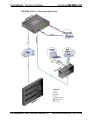
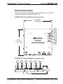
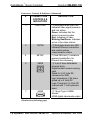
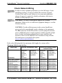
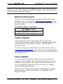
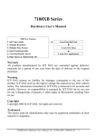
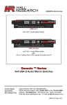
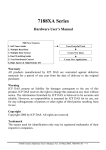
1
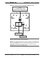
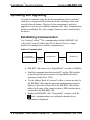
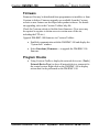
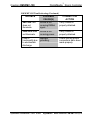
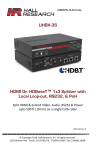
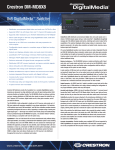
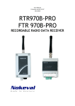
Crestron DM-RMC-100
DigitalMedia™ Room Controller
Operations & Installation Guide
This document was prepared and written by the Technical Documentation department at:
Crestron Electronics, Inc.
15 Volvo Drive
Rockleigh, NJ 07647
1-888-CRESTRON
All brand names, product names and trademarks are the property of their respective owners.
©2008 Crestron Electronics, Inc.
Crestron DM-RMC-100
DigitalMedia™ Room Controller
Contents
DigitalMedia™ Room Controller: DM-RMC-100
1
Introduction ............................................................................................................................... 1
Features and Functions ................................................................................................ 1
Applications................................................................................................................. 1
Specifications .............................................................................................................. 3
Physical Description.................................................................................................... 4
Industry Compliance ................................................................................................. 10
Setup ........................................................................................................................................ 11
Network Wiring......................................................................................................... 11
Installation ................................................................................................................. 11
Hardware Hookup ..................................................................................................... 13
Uploading and Upgrading........................................................................................................ 16
Establishing Communication..................................................................................... 16
Firmware ................................................................................................................... 17
Program Checks ........................................................................................................ 17
Problem Solving ...................................................................................................................... 18
Troubleshooting......................................................................................................... 18
Check Network Wiring.............................................................................................. 20
Reference Documents................................................................................................ 21
Further Inquiries ........................................................................................................ 21
Future Updates .......................................................................................................... 21
Return and Warranty Policies .................................................................................................. 22
Merchandise Returns / Repair Service ...................................................................... 22
CRESTRON Limited Warranty................................................................................. 22
Operations & Installation Guide – DOC. 6743A
Contents • i
DigitalMedia™ Room Controller
Crestron DM-RMC-100
™
DigitalMedia Room Controller:
DM-RMC-100
Introduction
The DigitalMedia™ (DM) Room Controller (RMC) is a digital media
receiver and display controller designed to convert DigitalMedia to
regular HDMI. It features a low-profile design perfect for installing
behind flat panel screens and above ceiling mounted projectors.
Features and Functions
•
•
•
•
•
•
•
•
•
DigitalMedia receiver and display controller
HDMI display output
Choice of standard DM or DM Fiber inputs
USB HID keyboard/mouse port
10/100 Ethernet LAN port
RS-232, IR, digital in and relay control ports
Meets requirements for plenum-rated ceilings
Low-profile design
Mounts to a 1900, 2-gang, 4-inch square or Euro electrical box
Applications
The following diagram shows a DM-RMC-100 in a small classroom
application.
Operations & Installation – DOC. 6743A
DigitalMedia™ Room Controller: DM-RMC-100 • 1
DigitalMedia™ Room Controller
Crestron DM-RMC-100
DM-RMC-100 in a Classroom Application
2 • DigitalMedia™ Room Controller: DM-RMC-100
Operations & Installation – DOC. 6743A
DigitalMedia™ Room Controller
Crestron DM-RMC-100
For more information on this and other DM-RMC-100 applications, refer
to the latest revision of the Crestron DigitalMedia™ Design Guide (Doc.
4789), which is available from the Crestron website
(www.crestron.com/manuals).
Specifications
Specifications for the DM-RMC-100 are listed in the following table.
DM-RMC-100 Specifications
SPECIFICATION
DETAILS
Power
DMNet Power Usage
Environmental
Temperature
Humidity
Heat Dissipation
Dimensions
Height
Width
Depth
Weight
Operations & Installation – DOC. 6743A
6 watts
(0.25 Amps @ 24 Volts DC)
41º to 104º F (5º to 40º C)
10% to 90% RH
(non-condensing)
21 BTU/Hr
4.53 in (11.51 cm)
5.15 in (13.08 cm)
1.41 in (3.58 cm)
0.86 lbs (0.39 kg)
DigitalMedia™ Room Controller: DM-RMC-100 • 3
DigitalMedia™ Room Controller
Crestron DM-RMC-100
Physical Description
This section provides information on the connections, controls and
indicators available on your DM-RMC-100.
DM-RMC-100 Overall Dimensions (Front View)
5.15 in.
(13.08 cm)
1
2
3
4
4.53 in
(11.51 cm)
5
DM-RMC-100 Overall Dimensions (Bottom View)
6
7
8
9
10
11
1.41 in
(3.58 cm)
4 • DigitalMedia™ Room Controller: DM-RMC-100
Operations & Installation – DOC. 6743A
DigitalMedia™ Room Controller
Crestron DM-RMC-100
DM-RMC-100 Overall Dimensions (Rear View)
12
13
14
Connectors, Controls & Indicators
#
CONNECTORS1,
CONTROLS &
INDICATORS
DESCRIPTION
1
PWR LED
2
DM LINK LED
(1) Green LED indicates
operating power supplied via
DMNet control network.
(1) Amber LED indicates a
connection to an upstream DM
device.
(Continued on following page)
Operations & Installation – DOC. 6743A
DigitalMedia™ Room Controller: DM-RMC-100 • 5
DigitalMedia™ Room Controller
Crestron DM-RMC-100
Connectors, Controls & Indicators (Continued)
#
CONNECTORS1,
CONTROLS &
INDICATORS
DESCRIPTION
3
VIDEO LED
4
CNTRL
5
SETUP
6
SENS
7
HDMI
(1) Red/green dual color LED
indicates video signal presence
and lock status:
Green: Indicates that the
device is receiving video
Red: Indicates no video
Blinking Red/Green: Indicates
errors in the video stream.
(1) Red/green dual-color LED
indicates Ethernet connection
and control system
communication status.
(1) Red LED and (1) miniature
recessed pushbutton, for
Ethernet auto-discovery.
(1) 2-pin 3.5mm detachable
terminal block;
Digital/contact closure sensing
input
Rated for 0-24 Volts DC,
referenced to GND
Input Impedance: 2.2k ohms
pulled up to 5 Volts DC
Logic Threshold: 2.5 Volts DC
nominal with 1 Volt hysteresis
band.
(1) 19-pin Type A HDMI
female;
HDMI digital video/audio output
(Continued on following page)
6 • DigitalMedia™ Room Controller: DM-RMC-100
Operations & Installation – DOC. 6743A
DigitalMedia™ Room Controller
Crestron DM-RMC-100
Connectors, Controls & Indicators (Continued)
#
CONNECTORS1,
CONTROLS &
INDICATORS
DESCRIPTION
8
USB
9
RELAY 1, 2
10
COM
11
IR 1, 2
12
DM INPUT2, 3
(1) USB Type A female
USB 1.1 port for mouse,
keyboard, game controller, or
other USB HID device.
(1) 4-pin 3.5mm detachable
terminal block comprising (2)
normally open, isolated relays;
Rated 2 Amp, 50 Volts AC/DC
MOV arc suppression across
contacts.
(1) 5-pin 3.5mm detachable
terminal block, bidirectional
RS-232 port;
Up to 115.2k baud, hardware
and software handshaking
support.
(1) 4-pin 3.5mm detachable
terminal block comprising (2)
IR/Serial ports;
IR output up to 1.1 MHz
1-way serial TT/RS-232 (0-5
Volts) up to 19200 baud.
(1) DM input composed of (2)
8-pin RJ-45 female, shielded;
Connects to DM output of a
DM switcher, transmitter, or
other DM device via DM-CBL
or CresCAT-D cable.4
(Continued on following page)
Operations & Installation – DOC. 6743A
DigitalMedia™ Room Controller: DM-RMC-100 • 7
DigitalMedia™ Room Controller
Crestron DM-RMC-100
Connectors, Controls & Indicators (Continued)
#
CONNECTORS1,
CONTROLS &
INDICATORS
DESCRIPTION
13
LAN3
(1) 8-wire RJ-45 female;
10BaseT/100BaseTX Ethernet
switch port.
14
DMNet5, 6
(1) 4-pin 3.5mm detachable
terminal block, DMNet port;
Connects to DMNet port of a
DM switcher, transmitter, or
other DM device via DM-CBL
or CresCAT-D cable.4
1. Interface connectors for SENS, RELAY, COM and IR ports are provided with
the unit.
2. The DM INPUT port consists of two separate RJ-45 connectors that are labeled
D and M. The D port carries video signal. The M port carries data. Refer to the
tables below, and on the following page, for the wires pin assignments.
D Port
PIN #
SIGNAL
1
2
4
5
7
8
3
6
DATA D0+
DATA D0DATA D1+
DATA D1DATA D2+
DATA D2CLKCLK +
DESCRIPTION
HDMI Blue
HDMI Blue
HDMI Green
HDMI Green
HDMI Red
HDMI Red
HDMI Clock
HDMI Clock
8 • DigitalMedia™ Room Controller: DM-RMC-100
Operations & Installation – DOC. 6743A
DigitalMedia™ Room Controller
Crestron DM-RMC-100
M Port
PIN #
SIGNAL
DESCRIPTION
1
2
3
6
4
5
7
8
+5V
I2C_DATA
E_TXE_TX+
E_RXE_RX+
I2C_CLK
+5V_RTN
+5V Power
HDCP & EDID Data
10/100BaseT Transmit
10/100BaseT Transmit
10/100BaseT Receive
10/100BaseT Receive
HDCP & EDID Clock
+5 Power Return
3. To determine which is pin 1 on the cable, hold the cable so that the end of the
eight pin modular jack is facing away from you, with the clip down and copper
side up. Pin 1 is on the far left.
4. For DigitalMedia wiring, use DM-CBL DigitalMedia Cable, CresCAT-D, or
quality CAT5e/CAT6 cable. Do NOT use low-skew cable. Refer to the latest
version of the Crestron DigitalMedia Design Guide (Doc. 4789) for complete
wiring guidelines.
5. DMNet wiring is not compatible with Cresnet® wiring. DMNet wiring cannot be
daisy chained.
6. Refer to the table below for the pinout of the 24 A B G port.
24 A B G Port
PIN #
SIGNAL
Color
24
A
B
G
24V DC
DMNet +
DMNet Ground
Red
Orange
Grey
Black
Operations & Installation – DOC. 6743A
DigitalMedia™ Room Controller: DM-RMC-100 • 9
DigitalMedia™ Room Controller
Crestron DM-RMC-100
Industry Compliance
This unit has been manufactured to comply with UL’s Standards for
Safety in Canada and the United States. Formal approval is pending.
As of the date of manufacture, the DM-RMC-100 has been tested and
found to comply with specifications for CE marking and standards per
EMC and Radiocommunications Compliance Labelling.
NOTE: This device complies with part 15 of the FCC rules. Operation is
subject to the following two conditions: (1) this device may not cause
harmful interference and (2) this device must accept any interference
received, including interference that may cause undesired operation.
This equipment has been tested and found to comply with the limits for a
Class B digital device, pursuant to part 15 of the FCC Rules. These limits
are designed to provide reasonable protection against harmful
interference in a residential installation. This equipment generates, uses
and can radiate radio frequency energy and if not installed and used in
accordance with the instructions, may cause harmful interference to radio
communications. However, there is no guarantee that interference will
not occur in a particular installation. If this equipment does cause harmful
interference to radio or television reception, which can be determined by
turning the equipment off and on, the user is encouraged to try to correct
the interference by one or more of the following measures:
Reorient or relocate the receiving antenna.
Increase the separation between the equipment and receiver.
Connect the equipment into an outlet on a circuit different from
that to which the receiver is connected.
Consult the dealer or an experienced radio/TV technician for help.
10 • DigitalMedia™ Room Controller: DM-RMC-100
Operations & Installation – DOC. 6743A
Crestron DM-RMC-100
DigitalMedia™ Room Controller
Setup
Network Wiring
When wiring the DMNet network, consider the following:
NOTE: DMNet wiring and Cresnet® wiring are not compatible.
• Use Crestron Certified Wire.
• Use Crestron power supplies for Crestron equipment.
• Provide sufficient power to the system.
• For DigitalMedia wiring, use DM-CBL DigitalMedia Cable,
CresCAT-D, or quality CAT5e/CAT6 cable. Do NOT use lowskew cable. Refer to the latest revision of the Crestron
DigitalMedia Design Guide (Doc. 4789) for complete wiring
guidelines.
CAUTION: Insufficient power can lead to unpredictable results
or damage to the equipment. Please use the Crestron Power
Calculator to help calculate how much power is needed for the
system (www.crestron.com/calculators).
For more details, refer to “Check Network Wiring” on page 20.
Installation
To prevent overheating, do not operate this product in an area that
exceeds the environmental temperature range listed in the table of
specifications.
The following is required for installation:
• DigitalMedia™ cable or CresCAT-D cable (not supplied)
terminated with RJ-45 connector for media signals and miniphoenix connector for DMNet signals. Refer to “Network Wiring”
on page 11.
• Phillips screwdriver (not supplied)
• Four #06-32 x 1/4" pan head Phillips screws (supplied)
Operations & Installation – DOC. 6743A
DigitalMedia™ Room Controller: DM-RMC-100 • 11
DigitalMedia™ Room Controller
Crestron DM-RMC-100
• Metal mounting plate (supplied)
• 4-Pin connector plugs (supplied)
It is assumed that DigitalMedia cable (DM-CBL) has been fed through an
installed two-gang electrical box, 85mm European or 1900 electrical box
(not supplied) and wiring has been verified. Use the following procedure
to install the DM-RMC-100.
1. Confirm that DMNet system power is OFF.
2. Attach supplied connector plugs according to the pinout on pages 8
and 9.
3. Attach metal mounting plate to electrical box using two Phillips
screws (not supplied).
4. Make DM-INPUT connections using DM-CBL.
• Connect the RJ-45 terminated blue shielded DigitalMedia cable
to the DM-INPUT D port.
• Connect the yellow RJ-45 terminated CAT5e/CAT6 cable to
the DM-INPUT M port.
• Connect the DMNet cable with the supplied connector plug to
the DM-RMC-100’s 24 A B G port.
5. Make the LAN connection to the DM-RMC-100’s LAN port using
an Ethernet cable with an RJ-45 connector.
6. Attach DM-RMC-100 to mounting plate using four #06-32 x 1/4"
Phillips screws (supplied) as shown in illustration on the following
page.
12 • DigitalMedia™ Room Controller: DM-RMC-100
Operations & Installation – DOC. 6743A
DigitalMedia™ Room Controller
Crestron DM-RMC-100
Mounting DM-RMC-100 into Electrical Box
METAL MOUNTING PLATE
(2019091)
DM-RMC-100
DRYWALL
MOUNTING SCREWS (4)
(2007215)
Hardware Hookup
Make the necessary connections as called out in the illustration that
follows this paragraph. Refer to “Network Wiring” on page 11 before
attaching the 4-position terminal block connector. Apply power after all
connections have been made.
Operations & Installation – DOC. 6743A
DigitalMedia™ Room Controller: DM-RMC-100 • 13
DigitalMedia™ Room Controller
Crestron DM-RMC-100
Hardware Connections for the DM-RMC-100 (Front View)
HDMI:
DISPLAY
HDMI
SENS:
CURRENT OR
MOTION SENSOR
IR:
IR INPUT FOR
DEVICE CONTROL
RELAY:
SCREEN AND LIFT
CONTROL
USB:
MOUSE, KEYBOARD OR
GAME CONTROLLER
14 • DigitalMedia™ Room Controller: DM-RMC-100
COM:
RS-232 SERIAL FOR
DEVICE CONTROL
Operations & Installation – DOC. 6743A
DigitalMedia™ Room Controller
Crestron DM-RMC-100
Hardware Connections for the DM-RMC-100 (Back View)
LAN:
ETHERNET EQUIPPED
DISPLAY OR OTHER DEVICE
DM INPUT
DMNet
NOTE: Ensure the unit is properly grounded.
NOTE: For optimum performance, Crestron strongly recommends using
DM-CBL DigitalMedia™ cable, available from Crestron. CresCAT-D or
high-quality CAT5e/CAT6 wiring may also be used with varying
performance. Do NOT use low-skew cable.
Operations & Installation – DOC. 6743A
DigitalMedia™ Room Controller: DM-RMC-100 • 15
DigitalMedia™ Room Controller
Crestron DM-RMC-100
Uploading and Upgrading
Crestron recommends using the latest programming software and that
each device contains the latest firmware to take advantage of the most
recently released features. However, before attempting to upload or
upgrade it is necessary to establish communication. Once communication
has been established, files (for example, firmware) can be transferred to
the device.
Establishing Communication
Use Crestron ToolboxTM for communicating with the DM-RMC-100;
refer to the Crestron Toolbox help file for details. There is a single
method of communication: indirect communication.
Indirect Communication
PC RUNNING
CRESTRON TOOLBOX
DM SWITCHER
SERIAL,
ETHERNET
OR USB
DM-RMC-100
DMNet
• DM-RMC-100 connects to a DigitalMedia™ switcher via DMNet.
• Establish communication between the PC and the DM switcher
as described in the latest version of a DigitalMedia Switcher
Operations Guide (Doc. 6755).
• Use the Address Book in Crestron Toolbox to create an entry for
the DM-RMC-100 using the expected communication protocol
(Indirect). Select the Cresnet ID of the DM-RMC-100 and the
address book entry of the control system or DM Switcher that is
connected to the DM-RMC-100.
• Display the DM-RMC-100’s “System Info” window (click the
icon); communications are confirmed when the device
information is displayed.
16 • DigitalMedia™ Room Controller: DM-RMC-100
Operations & Installation – DOC. 6743A
Crestron DM-RMC-100
DigitalMedia™ Room Controller
Firmware
Firmware files may be distributed from programmers to installers or from
Crestron to dealers. Firmware upgrades are available from the Crestron
website as new features are developed after product releases. For details
on upgrading, refer to the Crestron Toolbox help file.
Check the Crestron website to find the latest firmware. (New users may
be required to register to obtain access to certain areas of the site,
including the FTP site.)
Upgrade DM-RMC-100 firmware via Crestron Toolbox.
• Establish communication with the DM-RMC-100 and display the
“System Info” window.
• Select Functions | Firmware… to upgrade the DM-RMC-100
firmware.
Program Checks
• Using Crestron Toolbox, display the network device tree (Tools |
Network Device Tree) to show all network devices connected to
the control system. Right-click on the DM-RMC-100 to display
actions that can be performed on the DM-RMC-100.
Operations & Installation – DOC. 6743A
DigitalMedia™ Room Controller: DM-RMC-100 • 17
DigitalMedia™ Room Controller
Crestron DM-RMC-100
Problem Solving
Troubleshooting
The following table provides corrective action for possible trouble
situations. If further assistance is required, please contact a Crestron
customer service representative.
DM-RMC-100 Troubleshooting
TROUBLE
POSSIBLE
CAUSE(S)
CORRECTIVE
ACTION
Device does not
function.
Device is not
communicating
with the network.
Use Crestron Toolbox
to poll the network.
Verify network
connection to the
device.
Use the Crestron
Power Calculator to
help calculate how
much power is
needed for the
system.
Ensure proper video
signal is routed to
repeater.
Verify source is
operating.
Device is not
receiving
sufficient power.
Video LED
does not
illuminate.
Video LED
blinks red and
green.
Device is not
receiving video
signal.
Problem with video
source.
(Continued on following page)
18 • DigitalMedia™ Room Controller: DM-RMC-100
Operations & Installation – DOC. 6743A
DigitalMedia™ Room Controller
Crestron DM-RMC-100
DM-RMC-100 Troubleshooting (Continued)
TROUBLE
POSSIBLE
CAUSE(S)
CORRECTIVE
ACTION
DM LINK LED
does not
illuminate.
Device is not
receiving DMNet
signal.
Verify DMNet is
properly attached.
PWR LED does
not illuminate.
Device is not
receiving power.
Verify DMNet is
properly attached.
Loss of
functionality due
to electrostatic
discharge.
Improper
grounding.
Check that all ground
connections have been
made properly.
Operations & Installation – DOC. 6743A
DigitalMedia™ Room Controller: DM-RMC-100 • 19
DigitalMedia™ Room Controller
Crestron DM-RMC-100
Check Network Wiring
Use the Right
Wire
Calculate
Power
In order to ensure optimum performance over the full range of your
installation topology, Crestron Certified Wire and only Crestron
Certified Wire may be used. Failure to do so may incur additional
charges if support is required to identify performance deficiencies
because of using improper wire.
CAUTION: Use only Crestron power supplies for Crestron
equipment. Failure to do so could cause equipment damage or void the
Crestron warranty.
CAUTION: Provide sufficient power to the system. Insufficient
power can lead to unpredictable results or damage to the equipment.
The EIG connector on the DM switcher is used to jumper in external
power. Additional power is rarely required; switchers provide enough
power for their maximum configuration of room controllers and
repeaters. Please use the DMNet Power Calculator to help calculate
how much power is needed for the system
(www.crestron.com/calculators).
Refer to the following table for maximum cable lengths for various cables.
Maximum Cable Length by Type
Cable Type:
DM-CBL DigitalMedia Cable
CresCAT-D Crestron Home®
CAT5 AV Cable
Maximum
length
between,
before, or
after
repeaters
Maximum
total length
using up to 3
repeaters
Maximum
length
between,
before, or
after
repeaters
Maximum
total length
using up to 3
repeaters
720p, 1080i, 1080p/24
200 ft (60 m)
450 ft (137 m)
150 ft (45 m)
400 ft (120 m)
1024x768 @75Hz
200 ft (60 m)
450 ft (137 m)
150 ft (45 m)
400 ft (120 m)
1080p/60
150 ft (45 m)
450 ft (137 m)
100 ft (30 m)
400 ft (120 m)
1280x1024 @75Hz
150 ft (45 m)
450 ft (137 m)
100 ft (30 m)
400 ft (120 m)
1920x1200 @60Hz
150 ft (45 m)
450 ft (137 m)
100 ft (30 m)
400 ft (120 m)
1600x1200 @60Hz
125 ft (38 m)
450 ft (137 m)
75 ft (23 m)
400 ft (120 m)
1080p/60 Deep Color
100 ft (30 m)
400 ft (120 m)
Not Supported
Resolution:
20 • DigitalMedia™ Room Controller: DM-RMC-100
Operations & Installation – DOC. 6743A
DigitalMedia™ Room Controller
Crestron DM-RMC-100
NOTE: All Crestron certified DMNet wiring must consist of two twisted pairs. One
twisted pair is the +24V conductor and the GND conductor and the other twisted pair
is the A conductor and the B conductor.
Reference Documents
The latest version of all documents mentioned within the guide can be
obtained from the Crestron website (www.crestron.com/manuals). This
link will provide a list of product manuals arranged in alphabetical order
by model number.
List of Related Reference Documents
DOCUMENT TITLE
Crestron DigitalMedia Design Guide
DigitalMedia Switcher Operations Guide
Further Inquiries
If you cannot locate specific information or have questions after
reviewing this guide, please take advantage of Crestron's award winning
customer service team by calling Crestron at 1-888-CRESTRON
[1-888-273-7876].
You can also log onto the online help section of the Crestron website
(www.crestron.com/onlinehelp) to ask questions about Crestron products.
First-time users will need to establish a user account to fully benefit from
all available features.
Future Updates
As Crestron improves functions, adds new features and extends the
capabilities of the DM-RMC-100, additional information may be made
available as manual updates. These updates are solely electronic and
serve as intermediary supplements prior to the release of a complete
technical documentation revision.
Check the Crestron website periodically for manual update availability
and its relevance. Updates are identified as an “Addendum” in the
Download column.
Operations & Installation – DOC. 6743A
DigitalMedia™ Room Controller: DM-RMC-100 • 21
DigitalMedia™ Room Controller
Crestron DM-RMC-100
Return and Warranty Policies
Merchandise Returns / Repair Service
1.
No merchandise may be returned for credit, exchange or service without prior authorization
from CRESTRON. To obtain warranty service for CRESTRON products, contact an
authorized CRESTRON dealer. Only authorized CRESTRON dealers may contact the factory
and request an RMA (Return Merchandise Authorization) number. Enclose a note specifying
the nature of the problem, name and phone number of contact person, RMA number and
return address.
2.
Products may be returned for credit, exchange or service with a CRESTRON Return
Merchandise Authorization (RMA) number. Authorized returns must be shipped freight
prepaid to CRESTRON, 6 Volvo Drive, Rockleigh, N.J. or its authorized subsidiaries, with
RMA number clearly marked on the outside of all cartons. Shipments arriving freight collect
or without an RMA number shall be subject to refusal. CRESTRON reserves the right in its
sole and absolute discretion to charge a 15% restocking fee plus shipping costs on any
products returned with an RMA.
3.
Return freight charges following repair of items under warranty shall be paid by CRESTRON,
shipping by standard ground carrier. In the event repairs are found to be non-warranty, return
freight costs shall be paid by the purchaser.
CRESTRON Limited Warranty
CRESTRON ELECTRONICS, Inc. warrants its products to be free from manufacturing defects in materials
and workmanship under normal use for a period of three (3) years from the date of purchase from
CRESTRON, with the following exceptions: disk drives and any other moving or rotating mechanical
parts, pan/tilt heads and power supplies are covered for a period of one (1) year; touchscreen display and
overlay components are covered for 90 days; batteries and incandescent lamps are not covered.
This warranty extends to products purchased directly from CRESTRON or an authorized CRESTRON
dealer. Purchasers should inquire of the dealer regarding the nature and extent of the dealer's warranty, if
any.
CRESTRON shall not be liable to honor the terms of this warranty if the product has been used in any
application other than that for which it was intended or if it has been subjected to misuse, accidental
damage, modification or improper installation procedures. Furthermore, this warranty does not cover any
product that has had the serial number altered, defaced or removed.
This warranty shall be the sole and exclusive remedy to the original purchaser. In no event shall
CRESTRON be liable for incidental or consequential damages of any kind (property or economic damages
inclusive) arising from the sale or use of this equipment. CRESTRON is not liable for any claim made by a
third party or made by the purchaser for a third party.
CRESTRON shall, at its option, repair or replace any product found defective, without charge for parts or
labor. Repaired or replaced equipment and parts supplied under this warranty shall be covered only by the
unexpired portion of the warranty.
Except as expressly set forth in this warranty, CRESTRON makes no other warranties, expressed or
implied, nor authorizes any other party to offer any warranty, including any implied warranties of
merchantability or fitness for a particular purpose. Any implied warranties that may be imposed by law are
limited to the terms of this limited warranty. This warranty statement supersedes all previous warranties.
Trademark Information
All brand names, product names and trademarks are the sole property of their respective owners. Windows is a registered trademark
of Microsoft Corporation. Windows95/98/Me/XP/Vista and WindowsNT/2000 are trademarks of Microsoft Corporation.
22 • DigitalMedia™ Room Controller: DM-RMC-100
Operations & Installation – DOC. 6743A
Crestron DM-RMC-100
DigitalMedia™ Room Controller
This page is intentionally left blank.
Operations & Installation – DOC. 6743A
DigitalMedia™ Room Controller: DM-RMC-100 • 23
Crestron Electronics, Inc.
15 Volvo Drive Rockleigh, NJ 07647
Tel: 888.CRESTRON
Fax: 201.767.7576
www.crestron.com
Operations & Installation Guide – DOC. 6743A
(2022552)
12.08
Specifications subject to
change without notice.