1
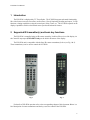
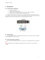
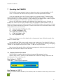
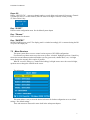
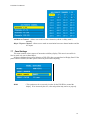
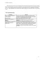
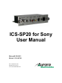
ICS-SP20 for Sony
User Manual
Manual# 050301
Model: ICS-SP20
205 Commercial Court
Morganville, NJ 07751
www.auroramultimedia.com
ICS-SP20 User Manual
TABLE OF CONTENT
1
INTRODUCTION .................................................................................................................................2
2
SUPPORTED IR TRANSMITTER(S) AND BASIC KEY FUNCTIONS .......................................2
3
QUICK START GUIDE .......................................................................................................................3
4
SONY DISPLAY SETTINGS...............................................................................................................3
5
LED FUNCTIONS ................................................................................................................................4
6
CONNECTIONS ...................................................................................................................................5
6.1
6.2
6.3
7
A/V & CONTROL CONNECTORS ........................................................................................................5
RF CONNECTOR ................................................................................................................................5
RJ11 SERVICE PORT CONNECTOR .....................................................................................................5
OPERATING THE ICS-SP20 ..............................................................................................................6
7.1
7.2
7.3
7.4
7.5
7.6
7.7
7.8
7.9
7.10
8
REMOTE CONTROL FUNCTIONS ........................................................................................................6
MENU STRUCTURE ...........................................................................................................................7
GENERAL SETTINGS .........................................................................................................................8
VIDEO SETTINGS ..............................................................................................................................8
AUDIO SETTINGS ..............................................................................................................................9
TUNER SETTINGS ..............................................................................................................................9
PANEL SETTINGS ............................................................................................................................10
CC SETTINGS .................................................................................................................................11
V-CHIP SETTINGS ...........................................................................................................................11
TROUBLESHOOTING ........................................................................................................................12
SPECIFICATIONS .............................................................................................................................13
8.1
8.2
8.3
8.4
9
10
APPLICABLE SIGNALS .....................................................................................................................13
CONNECTION TERMINALS ...............................................................................................................13
DIMENSIONS ...................................................................................................................................13
WEIGHT ..........................................................................................................................................13
LIMITED WARRANTY ....................................................................................................................14
FCC PART 15 STATEMENT ........................................................................................................14
ICS-SP20 User Manual
1 Introduction
The ICS-SP20 is a high quality TV Tuner/Scaler. The ICS-SP20 supports advanced functionality,
like video format /scan rate conversions, audio effects, Closed Captioning decoding and output, V-Chip
functions, cloning capabilities (using the control port), Sleep Timer, etc. The ICS-SP20 expands on the
displays capabilities with its own internal menu systems and advanced features.
2 Supported IR transmitter(s) and basic key functions
The ICS-SP20 is controlled using an IR remote controller. It utilizes IR receiver of the display via
the Control S output port (FWD-50PX1 only) or the built in IR sensor of the display.
The ICS-SP20 unit is compatible with the Sony IR remote transmitter(s) below (see Fig.1 & 2).
These transmitter(s) can be used to control the ICS-SP20.
Fig. 1
Fig. 2
For details of ICS-SP20 operation refer to the corresponding chapter of this document. Below is a
brief description of remote transmitters and the keys used for control of the ICS-SP20.
2
ICS-SP20 User Manual
Fig. 1 IR Remote
ON
STBY
ENTER
VOLUME +
VOLUME ARROWS
CHROMA
ID OFF
CONTRAST +
CONTRAST 0..9, digits
Function
Switch Power on
Switch Power off
Select option in menu
Also finishes input in dialog panels
Raises volume level
Lowers volume level
When menu active – move the cursor
up/down/left/right
Exit the current menu or dialog
Displays the Menu
Channel Up
Channel Down
When no dialog input active – directly enter
tuner channel number to switch to.
When dialog input active – enter digits.
3 Quick Start Guide
1. Make sure the Sony Display is off red LED and disconnected from power.
2. Remove the blank plate covering the card slot expansion slot or if an existing card is present it
must be removed from slot 1 (some models have 2 slots). If you have Sony model FWD-50PX1
you will need to loop the Control-S output into the Control-S of the ICS-SP20 using a 1/8” TRS
to 1/8” TRS cable. All other Sony displays do not need to do this.
3. Connect the appropriate video source to input connectors of ICS-SP20 (see “Connections”
chapter for details).
4. The RJ11 should be left unconnected as it is for Sony service purposes only. Warning: Damage
may occur if plug into a phone line or other RJ-11 connectors unintended for the port. This will
void the warranty.
5. Connect the power source to the display (refer to Operating Instructions of the Display).
6. The subsequent behavior of ICS-SP20 depends on its mode of operation (see the “Operating
Modes” chapter). A quick way to test correctness of setup is to use the “Power” key of Sony
remote to switch the “Power” state of ICS-SP20 on – (1) when pressing key on remote the upper
LED should blink fast (signaling the IR signal reception); (2) the ICS-SP20 and the panel should
switch on, which should be observable on the panel.
4 Sony Display Settings
The ICS-SP20 is designed and tested to work with your Sony display to provide TV Tuner source for
flexible use. To experience the best possible image quality, suggested adjustments are recommended for
your Sony display.
ICS-SP20 Monitor Selection
The ICS-SP20 has a setting for which Sony display you are using with your TV tuner device. Enter the
menu for the ICS-SP20 and under General Settings, select the correct model of your Sony display.
Normally it should auto detect the model but has a manual selection as well.
Screen adjustment (Horizontal / Vertical)
It may be necessary to adjust your display screen for best picture alignment on the first use of the ICSSP20 with your Sony display. Using the supplied Sony remote, use the HSIZE, VSIZE, HSHIFT and
3
ICS-SP20 User Manual
VSHIFT buttons inside the ICS-SP20 menus and make adjustments using the directional arrows until you
fill the screen and align the image to your preferred setting.
TVs and Displays often "overscan" the image slightly to ensure that difference in channel signals are not
reflected on the screen. You may choose to "overscan" the image and confirm that the image is filled on
the screen for different channels used.
5 LED functions
The two LEDs located on the ICS-SP20 indicate the current state of ICS-SP20 and may be useful for
troubleshooting.
During the startup (after powering on) the LEDs blink as the unit goes through self-test procedures
and firmware booting. If, after connecting the power, LEDs do not show any activity, then probably there
are problems with the power supply.
If the LEDs blink in alternative pattern -- upper/lower/upper/lower/etc – then the bootblock is active
and no valid main firmware is detected. This can happen if, for instance, the preceding firmware update
procedure was aborted for some reason. The bootblock waits for the new firmware upload, see the
“Firmware update” section of this document.
During the normal functioning of ICS-SP20 (when a valid firmware is loaded and self-test and
startup procedures are finished, which takes about 2 seconds), the LED functions are:
Upper LED:
•
•
Lower LED:
•
Flashes for 50ms once in 6 seconds when ICS-SP20 is attached to power supply, but
is in “Power Off” (“sleep”) state. Flashes for 50ms once in 3 seconds when ICSSP20 is in “Power On” state. This activity can be overridden by other activities of
the same LED.
Blinks fast when IR signal are detected. This can be used to see whether ICS-SP20
receives any IR control packets or not. This does not mean that ICS-SP20 recognizes
any IR command.
Switches ON when a control packet is sent to Sony Display Panel.
The upper LED has also another purpose – if the ICS-SP20 encounters an internal irrecoverable
error, it stops all activities and starts blinking the upper LED in series (series of blinks, then a longer
delay, then the series of blinks is repeated, so on).
4
ICS-SP20 User Manual
6 Connections
6.1
A/V & Control connectors
•
•
•
•
Composite video input
S-Video input (4-pin mini DIN)
Audio inputs (Left and Right RCA Phono are shared for Video and S-Video)
IR Input for direct connection of IR from IR control devices.
Example of interconnections for a display device, ICS-SP20, DVD/VCR (or other source of video),
and TV antenna or cable is shown below. Note that standard RCA cables for audio and video connections,
standard S-Video cable, or RF antenna cables are not supplied with the ICS-SP20.
6.2
RF connector
The coaxial connector (ANT) of ICS-SP20 is RF signal input – either aerial or cable TV, UHF/VHF,
if the ICS-SP20 shall be used as TV tuner.
6.3
RJ11 Service Port connector
RJ11 connector of ICS-SP20 is used as a service port for Sony. Nothing should be connected to this
port.
Warning: Damage may occur if plug into a different port such as a phone line. This will void the
warranty.
5
ICS-SP20 User Manual
7 Operating the ICS-SP20
The ICS-SP20 has many advanced features to enhance the typical viewing and usability of a TV
Tuner. To select the ICS-SP20 use the Sony remote to select the Option card slot YPbPr.
A user can switch the unit on or off, control volume level, switch the current TV channel, either
directly entering channel number, or browsing through valid channels using Channel +/- keys (usually
Arrow Up/Down key on a remote controller). “Valid” channels are the channels where a valid TV signal
was discovered during recent “channel scan” operation (in stand-alone mode).
Since the ICS-SP20 allows to attach several additional video signal sources to its AV inputs, to
facilitate user selection of these inputs ICS-SP20 maps some additional “channel numbers” to its AV
inputs. So when a user selects one of these “channels”, the ICS-SP20 switches to the respective AV input.
These reserved channel numbers are based on the values selected in the service menu and could be setup
in many different ways as shown below.
26 - Composite video IN (Default is 126)
97 - S-Video IN (Default is 127)
108 - RGB+HV IN (Default is 128)
2 - YPbPr IN (Default is 129)
10 - DVI IN (Default is 130)
When a user changes to one of the channels above the appropriate input will display instead of the
normal TV channel signal.
Note that RGB and YPbPr inputs actually share the same connection (15-pin female VGA-like), so
channels 128 and 129 change only interpretation of this input. For instructions on selecting or changing a
“channel” for an assigned input, please see section 7.6 “Map A/V Input to Channel”
More advanced functionality differs in different operating modes, which is described in more detail
below and in the subsequent chapters of this document.
7.1
Remote Control Functions
The ICS-SP20 is controlled using one of directly supported IR transmitters by Sony.
When no menu is active, usual keys of IR transmitter can be utilized to change volume level and
switch channels. These control keys are:
Key: Volume+/- (”VOL”)
“VOLUME “ – volume up/down adjustment
Key: Contrast +/- (“CH”)
Change TV channel. Number and label (if was defined) of the new channel is shown at top of screen for 5
seconds.
6
ICS-SP20 User Manual
Keys: 0-9
Dialog: “SWITCH TO” – enter new channel number, several digits can be entered if necessary. Channel
is switched to after a 3 seconds timeout (since the most recent digit is entered) or after pressing
TV/Video/FM or R key.
Key: “ID OFF”
Enter the main configuration menu. See the Menu System chapter
Key: “Chroma”
Enter selections for the menu.
Key: “ON/STBY”
Switch ICS-SP20 power on/off. The display panel is switched accordingly if it is connected using the RS232 port or IR output port.
7.2
Menu Structure
The menu system allows a user to control various aspects of ICS-SP20 configuration.
For all menus, up/down arrows move the cursor (yellow “selection” highlight) up/down. Central key
selects the current submenu/option and finishes text entry (passwords, channel labels, etc.). Left/right
arrow changes the currently active option, if possible.
When in “text edit” dialog (e.g., channel label editing), left/right arrows move the cursor left/right,
up/down arrows change the character at the cursor.
The main menu:
This menu allows a user to select the desired sub-menu for further configuration or to set default
settings. “Set default settings”.
These sub-menus are discussed in more detail in the subsequent chapters.
7
ICS-SP20 User Manual
7.3
General Settings
This menu allows control of various “general” aspects of ICS-SP20 behavior. Note that the *-marked
options are accessible only in Service mode, and not in Stand-alone mode.
A/V Input
Current time
Sleep timer
7.4
– Allows user to select the audio/video input source (among the built-in Tuner and
available AV-inputs)
– Allows to set the current time
– Allows user to set the sleep timer
Video Settings
Brightness
Contrast
Color
Startup Logo
Timer Logo
Video Position
-- Controls the brightness of the picture.
-- Controls the contrast of the picture.
-- Controls color saturation (0 corresponds to grayscale picture)
-- Enabled or disables “logo” picture display after ICS-SP20 powering on.
-- Time, in seconds, for which the “logo” picture is shown after ICS-SP20
powering on.
-- Opens the “Video position” submenu, allowing control of picture position on
screen.
8
ICS-SP20 User Manual
7.5
Audio Settings
Volume
Spatial Effect
7.6
-- Selects the current (default) volume level
-- Specifies the strength of 3D-spatial effect
Tuner Settings
Default Chan
-- Specifies the default channel, which will be selected upon ICS-SP20 power-up.
If this default channel is set to “0” -- the default channel will be the last channel
selected before the ICS-SP20 was powered off.
Rename Current Channel
-- Change the text label assigned to the current channel. This label is shown (if
enabled) on screen, along with the channel number, when the ICS-SP20 is
switched to this channel. Display of labels and channel numbers can be globally
disabled on enabled, see the subsequent menu options.
Show Label
-- Setting to enable will show up to an 8 character label specific to the channel
when changing channels.
Show Number -- Setting to enable will show up the channel number when changing channels.
Mode
-- Select tuner mode (channels allocation) to use, among broadcast and several
cable options.
Tune Channels -- Scans the channels, looking for valid signal presence, and “remembers” which
channels are valid and which are not. This “validity mask” is used then for
channel browsing using channel +/- buttons (so that a user browses through the
defined channels only). Note that before this operation ICS-SP20 must be
connected to RF-antenna or cable TV.
9
ICS-SP20 User Manual
Add/Remove Channels – Allows user to add or remove channels (edit the “validity mask”)
manually.
Map A/V Input to Channel – Allows user to make an association between a channel number and the
AV inputs.
7.7
Panel Settings
This menu controls various aspects of interaction with Sony display. This menu is accessible in
Service mode only (not in Stand-alone).
All these parameters do not affect behavior of ICS-SP20, they are transferred to Display Panel. If the
panel control is disabled, all other options effectively do not affect anything.
Model
-- This option must be set correctly in order for the ICS-SP20 to control the
display. If set incorrectly the size, color and position may not be set properly.
10
ICS-SP20 User Manual
Orbit Enable
Orbit Range
Orbit Cycle
7.8
-- Allows the enabling of Orbit mode on a per channel basis.
-- Selects how much orbit movement will occur.
-- Determines how often it will orbit.
CC Settings
This menu control Closed Caption decoder – CC signal type, and CC text color.
CC State
Foreground
Background
7.9
-- CC decoder state: Off – Closed Caption output is switched off.
-- Color for CC text foreground.
-- Color for CC text background.
V-Chip Settings
This menu configures V-Chip parental control system.
V-Chip Limit
Unrated chan.
-- Sets the threshold for program content indicator. Content rated as set in this
option (and below) can be viewed using the TV. Content rated above the setting
is rejected (red screen with message is shown).
-- Allows to enable/disable viewing of “unrated” channels. Off=Do not allow
viewing.
*- A user cannot change or reset password. Instead, to change the V-Chip limit user must enter the
V-Chip password.
11
ICS-SP20 User Manual
If the password is reset, the user is prompted to enter new password on his/her first access to V-Chip
limit. For all subsequent accesses the user will have to use the password that was specified during the first
access. In the event the password is forgotten the V-Chip settings can reset by holding the enter button
for 5 sec. When prompted for the password enter right, left, right, left, enter and it will be reset to default
values.
7.10 Troubleshooting
Symptom
Key on remote is pressed but
nothing happens
Image is Green
No control of the display via
Menus
No Image
Cannot switch to a particular TV
channel using channel +/browse keys.
Checks
See if the upper LED of ICS-SP20 is fast-blinking while
pressing key and aiming remote at IR sensor on the display.
If it is not -– check the batteries in the remote.
Make certain Option slot is select to YPbPr
Under panel settings check to see if correct model is
selected.
Check to see if Option Slot is selected as source
The channel is selectable by browsing keys only if it is
marked as “valid”. To be marked as “valid” the channel must
have a good TV signal during the “channel scan” operation.
Repeat the channel scan (making sure aerial/cable
connection is good). Also the channel validity can be edited
manually.
12
ICS-SP20 User Manual
8 Specifications
8.1
Applicable signals
Color system: NTSC (RF and AV inputs)
Scanning format: 525i (480i), 525p (480p)
Receiving RF signals – US Standard Air, US Standard Cable, Cable HRC, Cable IRC
Supported audio standards: auto-detection, BTSC-STEREO, BTSC-MONO+SAP
8.2
Connection terminals
Video IN (RCA)
S-Video IN (Mini DIN 4pin)
Audio Left Right – RCA Phono
ANT (aerial) IN – RF UHF/VHF
Sony Service Port – RJ11
IR IN – 3.5mm TRS (Tip – Signal, Ring – NC, Sleeve – Ground)
8.3
Dimensions
Height: 1.25”
Depth: 3.25”
Length: 5.25”
8.4
Weight
Approx. 0.8 lbs for ICS-SP20 unit and 1 lbs with all accessories and boxed
13
ICS-SP20 User Manual
9 Limited Warranty
Aurora Multimedia Corp. Warrants that this product is free of defects in both materials and workmanship for a
period of 24 months for parts and labor from date of purchase. During the warranty period, and upon proof of
purchase, the product will be repaired or replaced (with same or similar model) at our option without charge for
parts or labor for the specified warranty period (24 months parts and labor).
This warranty shall not apply if any of the following:
A) The product has been damaged by negligence, accident, lightning, water, act-of-God or mishandling; or,
B) The product has not been operated in accordance with procedures specified in operating instructions: or,
C) The product has been repaired and or altered by other than manufacturer; or,
D) The product’s original serial number has been modified or removed: or,
E) External equipment other than supplied by manufacturer, in determination of manufacturer, shall have
affected the performance, safety or reliability of the product.
In the event that the product needs repair or replacement during the specified warranty period, product should be
shipped back to Manufacturer at Purchaser’s expense. If requested, an estimate of any applicable charges will be
given before the repairs are made.
No other warranty, express or implied other than Manufacturer’s shall apply.
Manufacturer does not assume any responsibility for consequential damages, expenses or loss of revenue or
property, inconvenience or interruption in operation experienced by the customer due to a malfunction in the
purchased equipment. No warranty service performed on any product shall extend the applicable warranty period.
This warranty does not cover damage to the equipment during shipping and Manufacturer assumes no responsibility
for such damage.
This product warranty extends to the original purchaser only and will be null and void upon any assignment or
transfer.
10 FCC Part 15 Statement
RADIO AND TELEVISION INTERFERENCE
This equipment has been tested and found to comply with the limits for a Class B digital device, pursuant to Part 15
of the FCC rules. These limits are designed to provide reasonable protection against harmful interference in a
residential installation. This equipment generates, uses and can radiate radio frequency energy and, if not installed
and used in accordance with the instructions, may cause harmful interference to radio communications. However,
there is no guarantee that interference will not occur in a particular installation. If this equipment does cause
harmful interference to radio or television reception, which can be determined by turning the equipment off and on,
the user is encouraged to try to correct the interference by one or more of the following measures:
- Reorient or relocate the receiving antenna.
- Increase the separation between the equipment and the receiver.
- Connect the equipment into an outlet on a circuit different from that to which the receiver is connected.
- Consult the dealer or an experienced radio/TV technician for help.
You may also find helpful the following booklet, prepared by the FCC: "How to Identify and Resolve Radio-TV
Interference Problems." This booklet is available from the U.S. Government Printing Office, Washington D.C.
20402.
Changes and Modifications not expressly approved by the manufacturer or registrant of this equipment can void
your authority to operate this equipment under Federal Communications Commissions rules.
In order to maintain compliance with FCC regulations shielded cables must be used with this equipment. Operation
with non-approved equipment or unshielded cables is likely to result in interference to radio & television reception.
14