1
OVERVIEW MANUAL
VECTOR SYSTEM B
AND
VECTOR SYSTEM B+S3
INSTALIATION, USE, AND MAINI'ENANCE
PRELIMINARY MANUM.
Revision A
January 17, 1980
Copyright 1980 Vector Graphic Inc.
Since it is a preliminary release, there will be enhancements to this manual in
the near future. In particular, the area of system maintenance, not covered
herein, will be added.
Copyright 1980 by Vector Graphic Inc.
All rights reserved.
Disclaimer
Vector Graphic makes no representations or warranties with respect to the
contents of this manual itself, whether or not the product it describes is
covered by a warranty or repair agreement. Further, Vector Graphic reserves
the right to revise this publication and to make changes from time to time in
the content hereof without obligation of Vector Graphic to notify any person of
such revision or changes, except when an agreement to the contrary exists.
Revisions
The date and revision of each page herein appears at the bottom of each page.
'!he revision letter such as A or B changes if the MANUAL has been improved but
the PRODUCT itself has not been significantly m::xlified. '!he date and revision
on the Ti tie Page corres,FOnds to that of the page IOOSt recently revised. When
the product itself is modified significantly, the product will get a new
revision number, as shown on the manual's title page, and the manual will
revert to revision A, as if it were treating a brand new product. EACH MANUAL
SHOULD ONLY BE lEED WITH THE PRODOCT IDENTIFIED ON THE TITLE PAGE.
Rev. A
1/17/88
System B Installation, Use, and Maintenance Manual
The System B or its variations sold hereunder is sold ftas is·, with all faults
and without any warranty, either expressed or implied, including any implied
warranty of fitness for intended use or merchantability. However, the above
notwithstanding, VECTOR GRAPHIC, IN:., will, for a period of ninety (9~) days
following delivery to customer, repair or replace any System B or its
variations that is found to contain defects in materials or workmanship,
provided:
1. SUch defect in material or workmanship existed at the time the
System B or its variations left the VECTOR GRAPHIC, INC., factory;
2. VECTOR GRAPHIC, IN:., is given notice of the precise defect claimed
within ten (10) days after its discovery;
3. The System B or its variations is promptly returned to VECTOR
GRAPHIC, INC., at customer's expense, for examination by VECTOR GRAPHIC, INC.,
to confirm the alleged defect, and for subsequent repair or replacement if
found to be in order.
Repair, replacement or correction of any defects in material or workmanship
which are discovered after expiration of the period set forth above will be
performed by VECTOR GRAPHIC, INC., at B!;&er's expense, provided the System B or
its variations is returned, also at Buyer's expense, to VECTOR GRAPHIC, INC.,
for such repair, replacement or correction. In performing any repair,
replacement or correction after expiration of the period set forth above, Buyer
will be charged in addition to the cost of parts the then-current VECTOR
GRAPHIC, INC., repair rate. At the present time the applicable rate is $35.00
for the first hour, and $l8.~0 per hour for every hour of work required
thereafter. Prior to commencing any repair, replacement or correction of
defects in material or workmanship discovered after expiration of the period
for no-cost-to-Buyer repairs, VECTOR GRAPHIC, INC., will submit to Buyer a
written estimate of the expected charges, and VECTOR GRAPHIC, INC., will not
commence repair until such time as the written estimate of charges has been
returned by Buyer to VECTOR GRAPHIC, INC., signed by duly authorized
representative authorizing VECTOR GRAmIC, INC., to canmence with the repair
work involved. VECTOR GRAPHIC, INC., shall have no obligation to repair,
replace or correct any System B or its variations until the written estimate
has been returned with approval to proceed, and VECTOR GRAPHIC, INC., may at
its option also require prepayment of the estimated repair charges prior to
ccmnenciD,;J wo rk.
Repair Agreement void if the enclosed card is not returned to VECTOR GRAmIC,
INC. wi thin ten (10) days of end consttner purchase.
Rev. A 1/1718"
System B Installation, Use, and Maintenance Manual
Audience
This manual is intended for dealers,
distributors, salespersons, consultants,
and service personel. It requires a
minimll1l of technical knowledge.
Scope
It describes what the Vector Graphic
system Band its variations do, what major
canponents these systems consist of, how
to install, how to use (generally), and
how to maintain {generally} the systems.
Organization
For many dealers and users, no other
hardware manuals will be necessary, though
technicians will make use of the
more technical publications. Users will
reference specific software manuals,
depending on the particular application.
Rev. A 1/17/80
System B Installation, Use, and Maintenance Manual
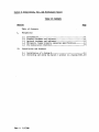
Section
Table of Contents
I.
Perspective
1.1
1.2
1.3
1.4
1.5
II.
Introduction ••••••••••••••••••••••••••••••••••••••••••••••• 1-1
Standard hardware and .software ••••••••••••••••••••••••••••• 1-1
Optional hardware and software••••••••••••••••••••••••••••• 1-2
Micropolis floppy diskette subsystem specifications •••••••• 1-3
Pre-installation checklist ••••••••••••••••••••••••••••••••• 1-4
Installation and Checkout
2.1
2.2
Installation of a System B••••••••••••••••••••••••••••••••• 2-l
Installing and using the Sprint 3 printer in a System B+53.2-8
ReV'. A 1/17/8a
~stem B
Installation, Use, and Maintenance Manual
I.
PmSP£Cl'IVE
1.1 Introduction
A System B is a general purpose microprocessor based computer. It is
delivered by Vector Graphic canpletely assembled and fully tested, including
both hardware and operating system software, and including t'WO quad density
mini-floppy disk drives.
1.2 Standard hardware and software
1) video console with a keyboard featuring the feel of an excellent electronic
typewri ter and a l0-key number pad;
2) Two quad-density Micropolis 5 1/4-inch diskette drives, providing a total of
630,000 characters of on-line storage (1232 256-character sectors per
diskette) ;
3) 56K of available random-access mE!n'Ory;
4) capability of interfacing to one printer at a time, either one of Vector's
system printers, or one of the many standard printers on the market;
5) Communications capability to interfacing to a standard asynchronous modem or
acoustic coupler; standard software with the system enables 30
characters/second (i.e. 300-baLrl) emulation of a "dumb" serial terminal;
6) Industry-compatible CP/M 2 operating system, allowing use of most CP/M
canpatible software on the system; and the MIX)S operating system, wh ich can
be used instead;
7) Microsoft BASIC-a0, release 5, one of the fastest and most IX>werful general
purpose languages available (used in conjuction with CP/M); and MicroIX>lis
BASIC, used in conjunction wi th MOOS;
a) Peachtree ready-to-use general business accounting software, including
programs for Accounts Receivable, Accounts Payable, General Ledger, Payroll,
and Inventory Managenent.
9) Additional powerful software developnent tools including SCOPE - an advanced
screen-oriented program editor; RAID - a full-screen simulator-debUjger for
assembly language programs; the ZSM assembler using the a080-superset
mnemonics; and the Extended Systems Monitor on PROM, allowing direct
manipulation of memory and input/output.
Rev.. A 1/17/89
1-1
System B Installation, Use, and Maintenance Manual
l0} Computer electronics consisting of:
a) Chassis with heavy duty power supply and l8-slot fully shielded and
terminated S-100 motherboard;
b) High-speed (4
MHz)
Z-80 CPU board;
c) Bitstreamer II input/output board, featuring 3 serial I/O channels, 2
parallel I/O channels;
d) 641< Dynamic RAM board;
e) 12K PROM/RAM board, which includes 12K of PROM sockets and lK of
scratch-pad RAM;
f) Flashwriter II Video board featuring a replacable character set;
g) Floppy disk drive controller board;
1.3 Optional hardware and software
1) The system can support two additional diskette drives, by adding the
MicroStor module;
2) The system can support up to four additional consoles (5 total), each
operating simultaneously and carrying on almost any task (for example, word
processing concurrently with accounting, on different consoles);
3) Vector Graphic offers two system printers, the Sprint 3 letter-quality
daisywheel printer, and the MP dot matrix printer which prints 150
characters per second. Vilen integrated at the factory with a system B, the
system. is called respectively a System. B+s3 or a system. B+MP.
4) Memorite word processing software from Vector Graphic.
5) Sophisticated graphics capabilities,. including Vector's High-resolution
Graphics Display Board, Vector's Video Digitizer Board if desired, a
graphics monitor, a TV camera (not available from Vector Graphic) to go with
the Digitizer, and associated software.
1-2
Rev. A
1/17/811
System B Installation, Use, and Maintenance Manual
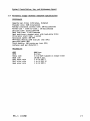
1.4 Micropolis floppy diskette subsystem specifications
PERFORMANCE
eapaci ty per drive: 315K bytes, fo rrnated
Transfer rate: 253K bits/second
Average rotational latency time: 100 milliseconds
Access t~e - track-to-track : 30 milliseconds
Settling time: 10 milliseconds
Head load t~e: 75 milliseconds
Head positioner: stepper motor with lead-screw drive
Drive motor start time: 1 second
Rotational speed: 300 RPM
Recording density 5248 bi ts per inch (BPI)
Recording mode: MPM
Track density: 100 tracks per inch (TPI)
Surfaces used per diskette: 1
RELIABILITY
M'lBF
MTTR
Media life
Head life
Soft error rate
Hard error rate
Seek error rate
Rev. A 1/17/80
8000 hrs.
0.5 hrs.
3 X 10 EXP 6 passes on single track
10 EXP 4 hrs.
1 in 10 EXP 9
1 in HI EXP 12
1 in 10 EXP 6
1-3
System B Installation, Use, and Maintenance Manual
1.5
Pre-installation check-list
The System B or System BfS3 can be ordered for either llS or 22S volt power
sources. Make sure that the system to be installed has the proper p::>wer supply
for the power supply in your region.
It is recanmended but not required that the power line to v.hich the canputer
is comected be a "dedicated" power line; that is, the line canes directly from
the building's p::>wer source, no other devices except another System B making
use of it, and that it is well grounded. '!he intent in this recanmendation is
to eliminate electronic "noise" on the power line which can affect the
reliability of the system, and to avoid the loss of data if a circuit breaker
is tripped because another device short circuits or too many devices are
connected. It is particularly critical that heavy machinery not be comected
to the same p::>wer line.
I):)
not install IOOre than two System B's per 2SA circui t.
Extension cords are not recanmended.
Special air-conditioning and raised floors are not required for a System B.
It will function in any nonnal office environment.
Do not install a System B in an abnormally dusty or dirty environments, due
to the effect on the disk drives and diskettes.
Make sure that there is adequate area for all equipnent, and that there is
adequate desk space next to the console. '!he printer MUST Nor be placed on top
of the computer mainframe. The console should be low enough for comfortable
typing. '!here must be some space on the left side and in back of the computer
mainframe, for ventilation.
Make sure that the console is not directly opposite a bright open window,
which will create glare on the surface of the screen.
If the carpet in the canputer's area is a shag or thick carpet, especially
if there is a lot of foot traffic near the computer or if the operator's chair
has rolling casters, there may be a build up of static in the operator and
passing people that can discharge into the system and cause the system to
malfunction or crash. If you anticipate or experience this problem, spray the
carpet in the machine's vicinity once a IOOnth, or IOOre often as needed, with
anti-static spray, available in many electronic supply and carpet distributors.
If the system is still affected by static, we recommend purchase of a 3M
anti-static mat to be placed on the floor in the canputer's area.
1-4
Rev. A 1/17/88
system B Installation, Use, and Maintenance Manual
2.1
Installation of a system B
1. Inspect all cartons for external signs of damage. If any damage is
observed, have the delivery agent note the damage on the shipping document.
Some shippers may wish to be present when the container is opened if
external damage is apparent.
2. Open all cartons, remove the packing material, and then withdraw the
equipment and manuals. If present, remove plastic bags from the equipment.
3. Place the computer chassis in a horizontal position and the "Mindless
Terminal" console as near as possible. Be very careful not to bump or jar
the canputer, because this can throw the disk drives out of aligrunent.
4. Remove the cover of the computer mainframe by unscrewing the four Phillips
head screws, two on each side. Note that one of the four screws may be
shorter than the others, and take note of \tohich hole it came from. carry
out a quick internal inspection, checking for obvious shipping damage and
loose boards due to shipping vibration. Press each board down firmly,
making sure it is fully inserted in its slot. If you find any obviously
broken boards or parts, do not use the equipment in order to avoid further
damage, or unexplained malfunction at the user's site at a later date.
Report the damage to the carrier, and contact qualified service personel, or
Vector Graphic.
Return the cover to the computer.- Make sure that the slotted edge is on
the same side as the slotted side of the bottom chassis. Do not replace the
screws yet.
5. Using the black power cable which comes with the system, connect the
computer to power. Connect the female end of the cable to the special
3-prong connector at the rear of the computer chassis.
6. Connect the console (the nMindless Tenninal ") to the computer chassis using
the 25-line flat ribbon cable found in the console's carton. The male end
of the cable plugs into the socket at the rear of the computer chassis
labeled nMindless Terminal." The female end plugs into the back of the
console. These plugs can only go in one way, so that there is no
possibility of error.
Rev. A
1/17/89
2-1
System B Installation, Use, and Maintenance Manual
7. Turn the power key in the front of the computer chassis. The RESET light
sho uld go on and the fan at the back of the corrputer should begin turning.
If the RESET light comes on but the fan does not, DO NOT operate the
computer, but contact service personel. Also contact service if the RESET
light does not go on but the fan does. If neither one goes on, check the
power connection and the fuse at the rear of the cOlJ.l>uter chassis. However,
if both go on, then after wanning up a short time, the console screen should
light up showing a banner identifying the ~ector Graphic Monitor.- The
-Monitor-, short for Extended Systems Monitor, is the piece of software
built into the system and which waits for canmands from the operator as soon
as the system is turned on.
8. If the RESET light goes on, but ,the screen does not light up, check the
connection to the console. If the "Vector Graphic Monitor- banner does not
show up, and something else shows up instead, turn the system off then on.
Try it several times if necessary, before contacting qualified service
personel.
9. Vtben the Monitor banner shows up, depress N on the keyboard, following the
MaN> prompt on the screen. N causes a memory test to occur. The acceptable
response is nE990 FF C3-, which should appear on the next line down within a
few seconds. Following this, another MON> prompt should appear on the next
line.
10. Following the MaN> prompt, depress Y.
This puts the system into an "echo·
mode, in which each key causes its-character to appear or causes the cursor
to move, but has no other function. Depress every key on the keyboard
except the ESC key, making sure that each one functions and that no keys
stick. When you have completed this test, then depress the ESC key, which
will take the system out of echo mode and put another MJN> prompt on the
screen.
11. Unwrap the CP/M system disk which canes with the system and insert it in the
right-hand drive (drive A in the CP/M nomenclature). Insert it with the
labeled side to the left and with the edge closest to the oval exposed
region going in first. Push it in until it clicks in place. Motmt the disk
by pressing the door slowly to the right, pausing briefly at the mid-po int,
when the spring-pressure increases. Full instructions for use of the disk
drives and handling floppy diskettes are fotmd in the CP/M 2 System Diskette
Introdl..X:tory Manual enclosed with the system.
2-2
Rev. A
1/17/88
System B Installation, Use, and Maintenance Manual
12. Boot up the CP/M operating system by depressing B on the keyboard, following
the MON> prompt. '!he red light on the right-hand drive should light up, an
audible click should be heard from the disk drive, and then a message
announcing the CP/M operating system should appear on the screen.
If this does not occur within 5 seconds of pressing B, depress RESET on
the computer chassis, then dismount the disk. (To dTsmount a disk, press
the door latch further to the right until it springs open.) Remove it from
the drive and make sure that (a) it is the serialized CP/M 2 disk that came
with the s¥?tem, (not from a different system), and (b) that it is oriented
correctly as described above. '!hen remount it carefully. Depress the RESET
key on the computer chassis and try the ~ command again.
If still no CP/M message appears, repeat the process of RESETING,
dismounting, checking the disk, remounting and rebooting once again. Then,
if there is no CP/M message, try the same process but use a CP/M 2 disk from
a different system, or if you have none, then try using the MOOS diskette
that came with the new system. If none of these diskettes will boot up, the
chances are that there is something wrong with the disk subsystem that
requires the help of service personel. If MOOS boots up but CP/M 2 does
not, then obtain a replacement CP/M 2 diskette having the same release
number (not necessarily the same serial number).
13. When CP/M boots up, you should see an 'A> prompt on the screen following the
sign on message. Type DIR (return) following the prompt.
(return) means
press the RETURN key. You do NOT have to use capital letters when typing a
CP/M command. You should immediately see a directory of the files on the
diskette, consisting of at least 5 lines of names. Make sure there is a
file naned BACKUP. '!his will be used next.
14. You are now going to copy the cP/M serialized diskette. '!his has the double
function that it tests the disk drives for compatibility and it gives you a
working copy of CP/M - the copy Which will become the Personalized CP/M 2
System Diskette. Insert and mount a completely unused diskette (or one
whose contents are not needed) in the left-hand drive (drive B in the CP/M
nomenclature). Make sure it is a Dysan, Scotch, or Maxell brand 16-sector
diskette. These are the only types of diskettes you should use with the
Vector Graphic system at this time, due to the high density of storage
employed; other brands have been fot.md unreliable in this system. At this
time, Scotch seems to be the roost reliable of the brands.
'!hen type BACKUP (return) following the A> prompt. In response to the
question "Source drive", press A. In response to the question "Destination
drive", press B. In response to the carunand "Press RETURN to begin", press
the RETURN key. The backup process will take approximately 3 minutes at
this point.
Rev. A 1/17/81
2-3
System B Installation, Use, and Maintenance Manual
15. At the end of the process, or earlier if an error occurs, you will see a
message on the screen following the last line. This message tells you
whether or not the copying process succeeded. Always look for it. If
successful, you will see "Copy complete".
If unsuccessful, you will see either "Bad source diskette" or "Bad
destination diskette". If unsuccessful, you should unload completely, and
remount the diskettes, then go to step 15 and try the process again wi th the
same diskettes. If it does not succeed a second time and you get DBad
destination diskette", try again using a different diskette in drive B,
because it is probably a defective diskette. If possible, try a different
brand of diskettes, fran one of the three brands mentioned above. Each time
you try it, unload and remount both diskettes. After you get a soccessful
backup, repeat the process again with the same diskettes. If you cannot
consistently get a successful backup, then contact service personnel to
adjust the drives.
16. In response to the statement" (R) to return to system
(B) execute backup
again", type an R to return to the CP/M executive (called "CCP"), or type B
if you want to repeat the backup process.
17. Cl1ce you have backed up your serialized CP/M diskette, the System B (without
its printer) is probably functioning satisfactorily. At this time, you may
follow the procedure in Section 3.6 of the CP/M 2 Introductory Manual, v.nich
configures the Personalized CP/M 2 System Diskette so that it makes full use
of the 56K of memory in the system (rather than using only 48K). You can
skip this procedure if CP/M will not be used by this particular user.
18. After configuring the Personalized diskette for use in a 56K system, remove
the serialized diskette, return it to its envelope and store it in a safe
place. Unless the Personalized diskette and all its copies are damaged, you
should never use the serialized diskette again. Unload the Personalized
CP/M 2 System Diskette, and label it as such, including the release number
and the serial number of the serialized diskette.
19. At this time, if you are using a printer, you should connect the printer to
the canputer. If your system is a System B+S3 from Vector Graphic, go NOW
to Section 2.2 and continue there.
If it is a serial printer emulating the Diablo protocol (such as Diablo
1610 or 1620, NEe Spinwriter, DataProduct serial daisywheel printer, or Qume
Sprint 5) or emulating the standard serial (sometime called Teletype)
protocol (su::h as a Decwriter or TI 810), and it runs at 1200 baLD or less,
simply connect it using a 25-line flat ribbon cable to the female socket
labeled RS-232C on the rear of the computer chassis. Some printers may
require a cable with male connectors at both ends. '!he allowable length of
cable has not yet been detennined, but it is selleral hundred feet at least.
2-4
Rev. A
1/17/88
System B Installation, Use, and Maintenance Manual
If it is a Sprint 3 printer from Vector Graphic, but not part of a System
B+S3 from the factory, connect the printer as described in the instructions
that come wi th the pr inter.
If it is one of the above kinds of printers, remove the cover of the
computer and check that the baud rate setting of Serial Channel C of the
Bitstreamer II board matches the speed of the printer. Find the Serial
Channel C swi tch near the upper left hand corner of the board, press the
desired rocker down and away from the OPEN designation, and press all other
rockers in the opposite direction. A Sprint 3 always operates at 1200 baud.
'!he system does NOT have to be turned off during this procedure.
If it is a Centronic's parallel printer, contact Vector Graphic for
instructions on interfacing.
If it is a TI 810 printer and you want to operate it at 1200 baud,
determine if it will be used to print word-processing text, long program
listings, or any kind of output \Itlich is dunped directly and continuously
from memory, with no breaks for disk access or calculation. If so, an
additional hardware modification to the system is required. This
modification is not necessary if the printer is used for normal
data-processing output. '!he modification is as follows: Remove the
Bitstreamer II board from the computer. Find pin 11 of the RS-232C
connector on the backplane of the computer chassis. Solder one end of a
wire to this pin (on the inside of the computer) and the other end to pin 1
of chip U26 on the Bitstreamer II board. Then solder one end of a short
jumper wire to pin 3 of U26 and the other end to pad 1 of jumper area N.
Jumper area N is near the bottom right side of the board. Finally, look at
the back side of the board and find the trace which leads downward from pad
1 of jumper area N. This trace narrows down just below the pad. Using a
sharp knife, cut this trace through the narrow part, scraping the trace on
each side of the cut so that the connection is thoroughly cut. '!hen, return
the board to the system. Having made this modification, you can carurunicate
to the printer at 9600 baud, which will speed up throUJhput by about 25%.
Set both Serial Channel C and the printer to 9600 baud.
If you are using a kind of printer not mentioned above, refer to both the
printer's manual and the Bitstreamer II manual for the infoonation you will
need to connect it, but Vector Graphic does not take responsibility for
supp:>rting this interface or its consequences.
You may now return the cover of the computer, again making sure the
slotted edge is on the same side as the slotted side of the chassis. Unless
you plan further hardware modifications (such as required by the Meroorite
\1iOrd processing software), you may screw the cover down.
Refer to the printer's manual for how to load ribbon, paper, printwheel,
how to connect it to p:>wer, and how to turn it on. (Instructions for
connecting and turning on the Sprint 3 in a System B+53 are found in Section
2.2 below.)
Rev.
A
1/17/88
2-5
~ B
2~.
Installation,
Use, and
Maintenance Manual
After connecting and turning on the printer, you have to configure the
Personalized CP/M 2 System Diskette to w:>rk with this system. First, mount
the Personalized CP/M 2 System Diskette i~ drive A (right-hand drive). If
you just turned the system on after connectirg the printer, boot up CP/M
from this diskette by depressirg B. If, however, the system has been on all
along, then just depress control-C after the A) prompt. This is the
so-called ·warm boot·, which tells the system a new CP/M diskette is in
drive A.
'!hen, following the A> prompt, type CONFIG (return). Answer the first
question by choosing the appropriate printer option. (IMPORTANT: If you are
using the Sprint 3, select the System Printer option.)
After selecting a printer option, go through the rest of the
COnfiguration without selecting any of the special options. The fastest way
to do this is to depress the RETURN key after the next two questions, and
then to depress Y when you are asked whether to save the configuration on
disk. Note: if you wish to understand IOOre of what can be done with CONFIG,
read section 3.7 of the CP/M. 2 Introductory Manual.
If you get an error message regarding the disk system, remount the
diskette in drive A, and while you are at it, make sure there is no
wri te-protect tab on the diskette. ('!his tab is a piece of metallized tape
over the cutout on the right edge of the diskette, described in Section 2.6
of the CP/2 Introdu::tory Manual.) Then try the CONFIG procedure again.
21. The best way to test the printer is to print several pages of material on
it. To do this, first turn the printer on and load continuous fan-fold
paper having II-inch page length. If the printer is wide enough, use
standard l4-inch wide fan-fold paper. If you are using a printer having an
add-on form-feed tractor (su::h as the Vector Sprint 3), and if you are not
familiar with it, do not try to use the form-feed tractor mechanism (which
usually comes in a separate carton) at this time. Simply roll the paper up,
as you would with an ordinary typewriter. Make sure that the paper is
loaded so that the print-heoo, when at the left edge of the printer, lines
up just to the right of the sprocket holes on the left edge of the paper.
Make sure the ribbon and printwheel (if any) are in place, and that the
cover is on. If the printer has a character spacirg switch on its front,
set it for 12 characters per inch.. (Sprint 3 has no such swi tch.) Then,
following the A> prompt type PIP I.ST:=DUMP.PRN (return). The canputer will
read this sample file fran the diskette and then print it out.
It will use up 5 sheets of paper. Make sure that the printer spaces down
to the top of each new sheet. (Note that it should do this, even thotgh you
did not specify the Autanatic Paging option in the CONFIG routine. This is
because the form-feed commands are within the DUMP.ERN text.) Make sure
that each line is even along the left margin and that the characters in the
line are level and evenly spaced. No lines should print past the right
margin, even if the printer is set for l~-characters per inch. Make sure
that the characters are printed completely and evenly. (If they are not, it
is probably because the printwheel or the ribbon is not loaded properly).
2-6
Rev. A
1/17,188
System B Installation, Use, and Maintenance Manual
22. If the printer cane wi til an add-on form-feed tractor, you may put it on the
printer now.
With the Sprint 3, or ().mle Sprint 5 printers, you must remove the top
cover of the printer and snap the tractor mechanism over the platen axel, so
that its gear meshes with the platen gear. 'Ib open the metal fingers which
snap over the platen axel, press on the metallic levers on each side of the
form feed tractor. In order to use a form-feed tractor, the platen pressure
lever on the right side of the Sprint 3 or Sprint 5 printer must be in the
forward position so that the paper slides through freely.
23. Once the System 8 and its printer is tested and working, you have
canp1eted the basic installation and check out of a System 8 or a System
8+S3. You may proceed to (1) make the necessary modifications for the
Memorite 'WOrd processiDj software (also called the w:>rd Management System),
(2) install additional terminals, (3) install graphics hardware and
software, (4) connect and test a nndem or acoustic coupler, or (5) make use
of the other software which canes with the system.
To do (1), refer to the instructions that come wi th the Memori te
software. To do (2), refer to the instructions which come with the
Time-Share Multi-User System 8 conversion package. 'Ib do (3), refer to the
appropriate technical manuals for graphics-related boards and softW3re. To
do (4) (connect a IOOdem or acoustic coupler), contact Vector Graphic. For
(5), refer to the manuals for that softW3re.
After all interior modifications are complete, you may screw down the
caoputer cover.
Rev. A 1/17/80
2-7
Syst:e:n B Installation, Use, and Maintenance Manual
2.2
Installing and using the Sprint 3 printer in a System Bf63
This section is only applicable if the internal interface comfX)nents of the
Sprint 3 Subsystem have already been installed within the computer chassis - in
other w:::>rds, it is a "System 8+53".
UNPACKIKJ
1. If not already done, remove the printer from its carton and any plastic bag.
The followiDJ items should be found in the carton: Sprint 3 printer, special
power cable (a thick round cable with a l2-pin mlex connector at one end),
4 round metal plugs, a print'Wheel, and a ribbon.
2. Inspect the printer for scratches, dents, loose or damaged parts, or other
signs of damage. N:>te any evidence of such damage on the invoice, and file
a claim with the carrier immediately, if the condition of the units
warrants.
3. UsiDJ a 7/16-inch (or 11 rnrn) socket wrench, remove the four screws securing
the printer to its shippiDJ pallet.
4. Insert the 4 round metal plugs in the holes vacated by the pallet screws on
the bottom of the printer.
5. Remove any paper wrapped around the platten.
6. Remove the top front cover by liftiDJ up under the edge at the front of the
printer.
7. IMPORTANT: Using cutting pliers, cut and remove the two plastic ties
securing the paper bail duriDJ shippiDJ.
8. IMPORTANT: CUt and remove the plastic tie securing the carriage assembly to
the printer chassis.
9. Now, load the print'Wheel and then the ribbon in the printer. Instructions
will be found in Chapter 3 of the Sprint 3 Maintenance/Training manual, if
you are not familiar with the procedure. Make sure the printwheel is
completely flat against the metal plate on the carriage. Make sure the
carriage mechanism is returned to the horizontal fX)si tion and the "c" button
is clicked-down. Make sure the ribbon cartridge is fully clicked-in and the
ribbon is threaded through both guides.
Ie.
Manually slide the print-head carriage from the left side of the printer all
the way to the right, and back again. Make sure it slides sm::>othly over the
complete raDJe. Make sure that there are no obstructions or foreign objects
inside the printer. Slide the carriage fully to the left. N:>w, return the
top cover of the printer. Make sure that the 1 ine down the center of the
print-hammer lines up, or is further to the left of, the e mark on the
printer cover.
2-8
Rev. A 1/17/8"
System B Installation, Use, and Maintenance Manual
CONNECTIN3
If the canputer is on, unmount any diskettes in the drives (you
do not have to ranove than fran the drives), and turn the computer off.
11. IMroRTANT:
12. Find the 5~-line flat ribl::x>n cable coming out fran inside the back of the
canputer chassis. Plug the far end of this cable into the socket on the
ri9ht side of the rear of the printer (\<ben you are facing the rear of the
prInter). Make sure that the colored edge of the cable is on the left side
of the cable when you are facing the rear of the printer. (~nnally, this
is the only way the connector will go in because of a restraining insert in
the connector.)
If the connector has screws for fastening to the
correspondi03 screw holes in the pr inter, tighten than down smggly ..
13. Find the printer power cable which came in the printer carton. Pll.:g the
l2-pin molex connector into the middle molex socket on the back panel of the
computer. It can only go in one way. Press it firmly as far in as it can
go.
14. Insert the other end of this cable into the connector on the left side of
the rear of the printer (\<ben you are facing the rear of the printer). It
will not go in very far until you start tightening down the screws in the
cable connector. However, it cannot be screwed down at all if you try to
attach it upside down, so that there is no way to make a mistake. Tighten
the two screws on the end.s of the connector alternately, until the connector
is in as far as it will go.
15. lbw, turn the canputer power on again. N::>te that the lights on the front
panel of the printer go on. '!he Sprint 3 printer in a System 8+53 does not
have a separate on/off swi tch. It is on \<benever the computer is on. If
the printer does not go on, check that the power cable is properly
installed. If it does go on, but one or more of the front panel lights does
not light up, refer to the troubleshooting tips below.
16. Otherwise, return to step 19 in Section 2.1, and follow the instructions
there for testing the printer subsystem. If the printer does not work
dur irx:J testing, you may refer to the troubleshooti03 po ints below.
Rev. A 1/17/80
2-9
Systen B Installation, Use, and Maintenance Manual
TROUBLESHoorIOO
If the Sprint 3 printer does not work:
(1) Make sure that you are camnandin:J it correctly.
(2) Check the R.l'lER light on the printer. If it is off, make sure the power
connection to the computer is completed. If necessary, cheek the System B
manual for a description of the cablill3.
(3) Check the READY light on the printer. If it is off but power is on,
this means either: the cover of the printer is not on tight, there is some
kind of jam in the mechanism preventing the printwheel from rotating
properly, there is something preventill3 the carriage from moving back and
forth freely, or there is sOllething IOOre seriously wrong with the printer.
Cleek the first three possibilities. If after correcting the problem the
printer does not start up by itself, you may have to reinitialize it by
rebooting the operating system, or in the case of IVk:!mori te software, issuill3
an RS command. If you cannot get the READY light to go back on, then refer
to the accompanying Sprint 3 Printer Maintenance/Training manual or
qualified service personnel.
(4) If the other lights are on, Cleck the RIDBON light on the printer.
it is off, this means that the ribbon is out. Load a fresh ribbon.
If
(5) If the POWER, READY, and RIBBON lights are on and it still does not
pr int, make sure the connection to the canputer is complete. Refer to the
SystEm B manual if necessary for a description of the cabling.
(6) If the above checks do not get the printer going, then refer to the
accompanying Sprint 3 Printer Maintenance/Training manual or qualified
service personnel.
2-UJ
Rev. A
1/17.181
System B Installation.. Use.. aD1 Maintenance ManUal
MA.INTENANCE OF THE SPRINT 3 PRINTER
'the Sprint 3 is a highly reliable device that will ~rk well for long
periods without attention. In a normal office environment, the Sprint 3
requires periodic lubrication and simple preventive maintenance every six
months for optimal performance and to prevent more serious breakdowns. In
very heavy use, this period should be shortened accordingly. Full
instructions for this maintenance procedure are given in the Sprint 3
Printer Maintenance/Training manual, included in the system's hardware
documenation. General maintenance procedures for the Sprint 3, for use by
service personnel, are found in the same manual.
ReV'. A
1/17,11!1
2-11