1
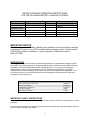
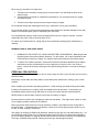
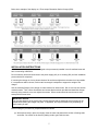
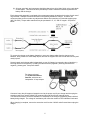
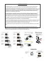
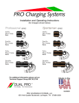
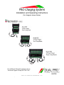
Installation and Operating Instructions
(for chargers shown below)
For additional information please call our
Technical Support Group 800.742.2740
062708
PRO CHARGING SYSTEMS, LLC
1551 Heil Quaker Boulevard, LaVergne, TN 37086-3539
INSTALLATION AND OPERATING INSTRUCTIONS
FOR THE FOLLOWING BATTERY CHARGING SYSTEMS:
Model #
Description
Total
Output
Recreation Series
PS1
PS2
PS3
One 6 Amp Bank
Two 6 Amp Banks
Three 6 Amp Banks
6 Amps
12 Amps
18 Amps
Independently charge 12V
batteries in the following
systems:
12V
12V, 24V
12V, 24V or 36V
IMPORTANT NOTICE
Please save and read all safety, operating and installation instructions before installing
or applying AC power to your PCS on-board battery charging system. Please contact
PCS with any product, installation, or service questions at technical support
(800.742.2740).
INTRODUCTION
Pro Charging Systems (PCS) has been manufacturing waterproof, on-board battery charging systems
since 1989. Our charging systems are designed and built tough to withstand intense vibration, extreme
temperature variations and submersion without damaging the unit. Our systems use temperature
compensation in order to fully charge a battery in hot or cold environments and are controlled by
microprocessors in order to assure precise control over each totally independent charging bank. All of
our chargers have true reverse polarity protection and incorporated a float maintenance mode upon
completion of each charge cycle.
TABLE OF CONTENTS
Important Safety Instructions.............................................................. Pages 2-3
Product Summary................................................................................Pages 4-5
Installation Instructions........................................................................Pages 5-6
Trouble Shooting.................................................................................Page 7
Warranty Information...........................................................................Page 8
IMPORTANT SAFETY INSTRUCTIONS
Use of attachments not recommended or sold by PCS may result in a risk of fire, electrical shock, or injury
to persons.
To reduce risk of damage to the electrical plug and power cord, always pull by the plug rather than by the
power cord when disconnecting charger.
2
When using an extension cord, make sure:
1. That pins on the extension cord plug are the same number, size and shape as those of the
charger’s plug;
2. That extension cord meets UL (Underwriters Laboratories, Inc.) acceptance and is in proper
operating condition;
3. That wire size is large enough for the ac ampere rating of charger.
Do not operate charger with a damaged cord or plug—replace the cord or plug immediately.
Do not operate charger if it has received a sharp blow, been dropped or otherwise damaged in any way;
contact our technical support group for assistance (800.742.2740).
Do not disassemble charger; contact technical support when service or repair is required. Incorrect
reassembly may result in risk of electrical shock or fire.
To reduce risk of electrical shock, unplug charger from outlet before attempting any maintenance or
cleaning.
WARNING: RISK OF EXPLOSIVE GASES
1. WORKING IN THE VICINITY OF A LEAD-ACID BATTERY IS DANGEROUS. Batteries generate
explosive gases during normal battery operation. For this reason, it is of utmost importance that
each time before using your charger, you read this manual and follow the instructions exactly.
2. To reduce risk of battery explosion, follow these instructions and those published by the battery
manufacturer and by the manufacturer of any equipment you intend to use in the vicinity of
battery. Review all cautionary markings on any product being utilized in or around the charging
device.
PERSONAL PRECAUTIONS
Someone should be within range of your voice or close enough to come to your aid when you work near a
lead-acid battery.
Have plenty of fresh water and soap nearby in case battery acid contacts skin, clothing, eyes, or other
surfaces.
Wear complete eye protection and clothing protection. Avoid touching eyes while working near battery.
If battery acid contacts skin or clothing, wash immediately with soap and water. If acid enters eye,
immediately flood eye with running cold water for at least 10 minutes and seek medical attention.
NEVER smoke or allow a spark or flame in the vicinity of a battery or engine.
Be extra cautious to reduce risk of dropping a metal tool onto battery. This might cause a spark or shortcircuit a battery, possibly resulting in an explosion.
Remove personal metal items such as rings, bracelets, necklaces, and watches when working with a
lead-acid battery. A lead-acid battery can produce a short-circuit current high enough to weld a ring, or
the like, to metal, causing a severe burn.
Use charger for charging a LEAD-ACID (lead acid, sealed lead acid, gel cell, and AGM) battery only. It is
not intended to supply power to a low voltage electrical system other than in a starter-motor application.
Do not use battery charger for charging dry-cell batteries that are commonly used with home appliances.
These dry cell batteries may explode, causing personal injury and damage to property.
3
NEVER charge a frozen battery.
PREPARING TO CHARGE
If it is necessary to remove the battery or batteries to charge, always remove grounded terminal from
battery first. Make sure all accessories are off, so as not to cause battery arcing.
Be sure the area around any battery is well ventilated while batteries are being charged. On occasion,
“gas fumes” may be present during charging and can be forcefully blown away by using a piece of
cardboard or other nonmetallic material as a fan. Proper ventilation is always recommended in the
charging area.
Clean all of the battery terminals. Be careful to keep corrosion from coming into contact with eyes.
Add distilled water in each cell (wet cell batteries) until battery acid reaches level specified by battery
manufacturer. This helps purge excessive gas from cells. Do not overfill. For a battery without cell caps,
carefully follow manufacturer’s recharging instructions.
Study all battery manufacturers’ specific precautions such as removing or not removing cell caps while
charging and recommended rates of charge.
Extension cords should be industrial grade/heavy duty UL approved and grounded. Check extension
cord before use for damage, bent prongs and cuts. Replace if damaged.
Always make your extension cord connection on the charger side first. After connecting the extension
cord to the charger, proceed to plug the extension cord into a 120VAC GFCI protected (Ground Fault
Circuit Interrupt) A/C outlet. The unit will operate with a VAC input range of 90VAC-264VAC.
Always remove the extension cord from the A/C outlet first when charging is completed followed by
unplugging the charger.
PRODUCT SUMMARY
General Operation:
Use the following guidelines in this manual to install your fully automatic PCS battery charging system.
Assure that the area around your charger and batteries is properly ventilated. Connect your extension
cord with no A/C power present to the battery charger and proceed to plug your extension cord in at a
nearby A/C outlet.
Once you plug in your PCS battery charging system, your batteries will be simultaneously and
independently charged to 100%. Unlike systems that utilize one large charger to attempt to charge
multiple batteries, your system utilizes a totally independent battery charger for each battery. Each
charging bank will remain in a “float” stage once the battery is charged and then monitor and/or maintain
the battery indefinitely.
We recommend that you leave your system plugged in. This will reduce sulfation on the lead plates of
the batteries and allow your PCS charging system to keep your batteries fully maintained and ready to
perform at their best.
Independent Charging Bank Indications
When your battery charging system is activated, each bank provides charging information utilizing 1 red
Light Emitting Diode (LED) indicator and one green Light Emitting Diode (LED) indicator. The Red
(CHARGING) LED indicates d/c current is flowing to the battery and the Green (READY) LED indicates
that the charger has finished it's bulk and absorption stage and has entered the float maintenance mode.
There is also a Green (POWER) LED that illuminates to indicate that power is supplied to the charger
when it is plugged in properly to a functioning A/C outlet.
4
Below is an example of the display on a Three output Recreation Series Charger (RS3):
INSTALLATION INSTRUCTIONS
All PCS battery charging systems are designed to be permanently installed in a well-ventilated area and
have no mounting restrictions.
Do not make any electrical connections to the power supply (AC) or to a battery (DC) until the installation
process has been completed.
If mounting the charger in a boat, please choose a flat surface as high above the water level as possible.
If a compartment wall is chosen, make certain its strength is adequate to support the weight of the
charger.
Use the mounting flanges of the charger to mark locations for starter holes. Drill a 1/16 inch hole at each
marked location. Then, utilize all stainless steel screws that have been provided and install the charger
securely, being cautious not to over tighten the screws. Silicon sealer should be used to secure and
waterproof the screw holes.
IMPORTANT NOTICE
The mounting brackets of the system may contain keyholes that are designed so that screws can be
started before putting the charger into place. If applicable, the keyhole locations vary depending on
which model you own.
Before making any connections, prepare batteries as follows:
(a) With caps securely in place, thoroughly clean the case and posts with a solution of baking soda
and water. Be careful not to allow any baking soda to get inside the case.
5
(b) All posts, terminals, and connectors should be cleaned to a shiny bright finish, using a wire brush
or sand paper. This should be done periodically to assure maximum conductivity between the
battery and the charger.
Each charge cable assembly is equipped with a temperature sensor located at the junction of each set of
ring terminals. Attempts to shorten the cables could partially disable the charger. Therefore, we
recommend that you do not make any adjustments without first consulting our technical support group
(800.742.2740). Proper cable extensions may be purchased in 5’, 10’, and 15’ lengths. See picture
below.
To connect the charger to the battery (batteries), route your charge cables from the charger to the
batteries, being cautious to avoid sharp objects, and use the supplied wire ties to hold them securely and
neatly in place.
Securely attach each charge cable independently to one 12V battery by connecting the red (positive/+)
lead ring terminal to the positive (+) battery post and the black (negative/-) lead ring terminal to the
negative (-) battery post. See picture below:
(-)
(+)
(-)
(+)
The charger pictured
is a Professional Series
Dual Pro, which has two
independent 15 amp outputs.
Connect a heavy duty UL approved extension cord to the power cord of your charger and then plug the
extension cord into a nearby 120VAC GFI protected (Ground Fault Circuit Interrupt) outlet.
You should now observe a red LED indication on each bank of the charger representing each individual
battery being charged. The voltage of each battery will reflect the number of LED indicators illuminated.
When charging is complete, remove the extension cord from the 120VAC outlet first and then unplug the
charger.
6
TROUBLE SHOOTING
PROBLEM: No LED indicators illuminate on the charger.
Solution Sequence: Check the AC power supply from its source through all connecting points up to the
charger by using a meter or test light to confirm that current is being delivered to the charger.
PROBLEM: The Green (POWER) LED is illuminated, but the Red (CHARGING) LED and the Green
(READY) LED are off.
Solution Sequence: This indicates that the charger does not recognize that it is connected properly to a
battery that has at least 5Volts. With the AC power supply cord unplugged, check the ring terminals for
correct polarity (Red to positive or +) and (Black to negative or - ). Also check for corrosion free secure
connections to the batteries. Check in-line fuses in charge cable for any signs of opening or corroded
connections. Call the technical support group for further assistance (800.742.2420).
PROBLEM: The RED (CHARGING) LED remains illuminated for more than 16 hours and the Green
(READY) LED does not come on.
Solution Sequence: This indicates that the battery is not reaching a sufficient voltage to indicate that the
battery is fully charged. Disconnect AC power to the charging system. On multi bank chargers, remove
the charge cable assembly of the affected bank from the battery and attach it to another battery in the
boat. Take the original charge cable assembly from this battery and attach it to the battery from which
you removed the first cable. Plug the charger in and observe the LED indications. If the rapid LED
sequence (red to green repeatedly) occurs on a different bank of the charger, this confirms the existence
of a battery problem.
On single bank systems, simply try the charger on another battery. If the charger now operates normally
(steady red LEDs or changes to green and holds), this indicates a possible problem with the original
battery.
If the same bank continues to malfunction, please call our technical support group (800.742.2740).
PROBLEM: The green (READY) LED was illuminated before disconnecting the power from the
charger, but upon reconnection, the red (CHARGING) LED appears and remains on.
Solution Sequence: This is normal operating procedure for the system and simply indicates that a reanalysis of the battery status has been initiated and after a series of steps, the green LED will illuminate.
7
LIMITED WARRANTY
Pro Charging Systems, LLC (PCS) makes this Limited Warranty only to the original retail purchaser.
PCS warrants this battery charger for two years from the date of retail purchase against defective
materials and/or workmanship. If such defects should occur, this unit will either be repaired or replaced at
the discretion of the manufacturer. It is the responsibility of the original purchaser to return the charger
along with proof of purchase, transportation, and/or any mailing or handling charges prepaid to the
manufacturer or its authorized representative.
This limited warranty is void if the product is misused, improperly maintained, handled carelessly or
incorrectly operated. Additionally, this warranty is void if the charger is disassembled, the charger’s
charge cables are cut, the power cord is cut off, the charger is altered without authorization from PCS, the
serial number is removed, or repair is attempted by anyone other than an authorized representative.
PCS makes no other warranty other than this limited warranty and expressly excludes any implied
warranty, including warranty for any incidental or consequential damages.
This is the only expressed limited two year warranty authorized by PCS and does not authorize anyone to
assume or make any other obligation towards the product other than this three year Limited Warranty.
Some states do not allow limitation of incidental or consequential damages.
This warranty gives you specific legal rights and you may also have other rights which vary from state to
state.
Please call Pro Charging Systems, LLC (800.742.2740) for full warranty information and/or service.
Below are some of our other options in chargers and battery accessories. Call our technical support
group for more detailed information or visit our web site www.dualpro.com.
8