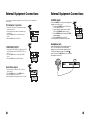
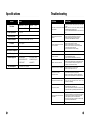
1
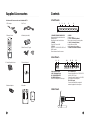
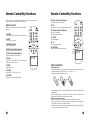
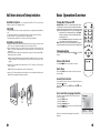
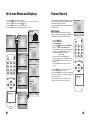
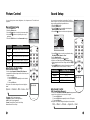
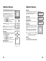
Operating Guide | W a r r a n t y
zenith L10V22 LCD-TV
Model Number | L10V22 | LCD-TV
Zenith will repair or replace your product, at Zenith’s option, if it proves to be defective in material or
workmanship under normal use, during the warranty period listed below from the date of original
consumer purchase. This warranty is available only to the original, end user purchaser of the product and
effective only when used in the United States, excluding U.S. Territories. Zenith is not responsible for
deinstallation or reinstallation of unit.
WARRANTY PERIOD:
Labor: One Year from date of purchase.
Parts: One Year from the date of purchase.
HOW SERVICE IS HANDLED:
Swap service: Please retain your bill of sale for
proof of warranty and box to return unit if needed.
Please call 1-800-984-9349 for complete shipping
and handling instructions.
Repair or replacement may be new or
remanufactured product. Please see below for
further information.
THIS WARRANTY IS IN LIEU OF ANY OTHER WARRANTY, EXPRESSED OR IMPLIED, INCLUDING
WITHOUT LIMITATION, ANY WARRANTY OF MERCHANTABILITY OR FITNESS FOR A
PARTICULAR PURPOSE. TO THE EXTENT ANY IMPLIED WARRANTY IS REQUIRED BY LAW, IT
IS LIMITED IN DURATION TO THE EXPRESSED WARRANTY PERIOD ABOVE. ZENITH WILL NOT
BE LIABLE FOR ANY INCIDENTAL, CONSEQUENTIAL, INDIRECT, SPECIAL OR PUNITIVE DAMAGES OF ANY NATURE, EVEN IF ADVISED OF THE POSSIBILITY OF SUCH DAMAGES,
INCLUDING WITHOUT LIMITATION LOST PROFITS, LOST OR CORRUPTED PROGRAMMING OR
DATA, OR ANY OTHER DAMAGE WHETHER BASED IN CONTRACT, TORT OR OTHERWISE.
Some states do not allow the exclusion or limitation of incidental or consequential damages or limitations
on how long an implied warranty lasts, so the above exclusion or limitation may not apply to you. This
warranty gives you specific legal rights and you may also have other rights that vary from state to state.
THIS LIMITED WARRANTY DOES NOT APPLY:
• To damages or operating problems that result from shipping, installation, adjustment of user
controls, calibration, maintenance or failure to maintain, or separate system components.
• To damages or operating problems that result from normal wear and tear, misuse, abuse,
operation outside environmental specifications or contrary to the requirements and precautions
in the Operating Guide, accident, lightening strikes or other natural causes, modification or
alteration, incorrect electrical current or voltage, signal reception or input, computer software, or
institutional or commercial use.
Therefore, you pay for the cost of repair or replacement under these circumstances.
CUSTOMER ASSISTANCE NUMBERS:
To prove warranty coverage:
Retain your dated sales receipt to prove date of purchase. Legible copy of your sales
receipt must be submitted at the time warranty service is provided.
To obtain where-to-buy, product assistance or customer assistance:
Call 1-877-9 Zenith (1-877-993-6484) (Mon. - Fri. 7:00 AM to 8:00 PM and Sat. 8:00 AM
to 5:00 PM CST)
Please select the appropriate option from the menu.
© Copyright 2002 Zenith Electronics Corporation
WARR-DV2/02
206-3801
Issue*
©Copylight 2002, Zenith Electronics Corporation
IMPORTANT SAFETY INSTRUCTIONS
Warnings
WARNING
RISK OF ELECTRIC SHOCK
DO NOT OPEN
WARNING :
TO REDUCE THE RISK OF ELECTRIC SHOCK DO NOT REMOVE COVER (OR
BACK). NO USER SERVICEABLE PARTS INSIDE. REFER SERVICING TO
QUALIFIED SERVICE PERSONNEL.
The lightning flash with arrowhead symbol, within an equilateral triangle,
is intended to alert the user to the presence of uninsulated “dangerous
voltage” within the product’s enclosure that may be of sufficient
magnitude to constitute a risk of electric shock to persons.
The exclamation point within an equilateral triangle is intended to alert
the user to the presence of important operating and maintenance
(servicing) instructions in the literature accompanying the appliance.
WARNING:
TO PREVENT FIRE OR SHOCK HAZARD DO NOT EXPOSE THE SET TO RAIN OR MOISTURE.
NOTE TO CABLE/TV INSTALLER:
This reminder is provided to call the cable TV system installer’s attention to Article 820-40 of
the National Electric Code (U.S.A.). The code provides guidelines for proper grounding and, in
particular, specifies that the cable ground shall be connected to the grounding system of the
building, as close to the point of the cable entry as practical.
REGULATORY INFORMATION:
This equipment has been tested and found to comply with the limits for a Class B digital
device, pursuant to part 15 of the FCC Rules. These limits are designed to provide reasonable
protection against harmful interference when the equipment is operated in a residential
Installation. This equipment generates, uses and can radiate radio frequency energy and, if
Not installed and used in accordance with the instruction manual, may cause harmful
interference to radio communications. However, there is no guarantee that interference will not
occur in a particular installation. If this equipment does cause harmful interference to radio or
television reception, which can be determined by turning the equipment off and on, the user is
encouraged to try to correct the interference by one or more of the following measures:
• Reorient or relocate the receiving antenna.
• Increase the separation between the equipment and receiver.
• Connect the equipment into an outlet on a circuit different from that to which the receiver is
connected.
• Consult the dealer or an experienced radio/TV technician for help.
CAUTION:
Do not attempt to modify this product in any way without written authorization from Zenith
Electronics Corporation. Unauthorized modification could void the user’s authority to operate this
product.
Important safeguards for you and your new product
Your product has been manufactured and tested with your safety in mind. However, improper use
can result in potential electrical shock or fire hazards. To avoid defeating the safeguards that have
been built into your new product, please read and observe the following safety points when
installing and using your new product, and save them for future reference.
Observing the simple precautions discussed in this operating guide can help you get many years
of enjoyment and safe operation that are built into your new product.
This product complies with all applicable U.S. Federal regulations and voluntary safety standards.
1. Read Instructions
9. Attachments
All the safety and operating instructions should
be read before the product is operated.
Do not use attachments not recommended by
the product manufacturer as they may cause
hazards.
2. Follow Instructions
All operating and use instructions should e
followed.
3. Retain Instructions
The safety and operating instructions should be
retained for future reference.
4. Heed Warnings
All warnings on the product and in the
operating instructions should be adhered to.
5. Cleaning
Unplug this product from the wall outlet before
cleaning. Do not use liquid cleaners or aerosol
cleaners. Use a damp cloth for cleaning.
6. Water and Moisture
Do not use this product near water for
example, near a bathtub, washbowl, kitchen
sink, or laundry tub, in a wet basement, or near
a swimming pool.
7. Accessories, Carts, and Stands
Do not place this product on a slippery or tilted
surface, or on an unstable cart, stand, tripod,
bracket, or table. The product may slide or fall,
causing serious injury to a child or adult, and
serious damage to the product. Use only with a
cart, stand, tripod, bracket, or table
recommended by the manufacturer, or sold
with the product. Any mounting of the product
should follow the manufacturer’s instructions,
and should use a mounting accessory
recommended by the manufacturer.
8. Transporting Product
A product and cart combination should be
moved with care. Quick stops, excessive force,
and uneven surfaces may cause the product
and cart combination to overturn.
COMPLIANCE:
The responsible party for this product’s compliance is:
Zenith Electronics Corporation, 2000 Millbrook Dr., Lincolnshire, IL 60069, USA • Phone: 1-847941-8000.
2
10. Ventilation
Slots and openings in the cabinet are provided
for ventilation and to ensure reliable operation
of the product and to protect it from
overheating, and these openings must not be
locked or covered. The openings should never
be blocked by placing the product on a bed,
sofa, rug, or other similar surface. This product
should not be placed in a built-in installation
such as a bookcase or rack unless proper
ventilation is provided or the manufacturer ’s
instructions have been adhered to.
11. Power Sources
This product should be operated only from the
type of power source indicated on the marking
label. If you are not sure of the type of power
supply to your home, consult your product
dealer or local power company. For products
intended to operate from battery power, or
other sources, refer to the operating
instructions.
12. Power Cord Polarization
This product is equipped with a three-wire
grounding-type plug, a plug having a third
(grounding) pin This plug will only fit into a
grounding-type power outlet. . This is a safety
feature. If you are unable to insert the plug into
the outlet, contact your electrician to replace
your obsolete outlet. Do not defeat the safety
purpose of the grounding-type plug.
13. Power Cord Protection
Power-supply cords should be routed so that
they are not likely to be walked on or pinched
by items placed upon or against them, paying
particular attention to cords at plugs,
convenience receptacles, and the point where
they exit from the product.
PORTABLE CART WARNING
3
IMPORTANT SAFETY INSTRUCTIONS
14. Outdoor Antenna Grounding
19. Servicing
If an outside antenna or cable system is
connected to the product, be sure the antenna
or cable system is grounded so as to provide
some protection against voltage surges and
built-up static charges. Article 810 of the
National Electrical Code (U.S.A.), ANSI/NFPA
70 provides information with regard to proper
grounding of the mast and supporting
structure, grounding of the lead-in wire to an
antenna discharge unit, size of grounding
conductors, location of antenna-discharge unit,
connection to grounding electrodes, and
requirements for the grounding electrode.
Example of Grounding According to National
Electrical Code Instructions
Do not attempt to service this product yourself
as opening or removing covers may expose
you to dangerous voltage or other hazards.
Refer all servicing to qualified service
personnel.
ANTENNA
LEAD IN
WIRE
GROUND CLAMP
ANTENNA
DISCHARGE UNIT
(NEC SECTION 810-20)
GROUNDING CONDUCTORS
(NEC SECTION 810-21)
GROUND CLAMPS
ELECTRIC SERVICE
EQUIPMENT
NEC - National Electrical Code
POWER SERVICE GROUNDING
ELECTRODE SYSTEM
( N E C A RT 2 5 0 , PA RT H )
15. Lightning
For added protection for this product (receiver)
during a lightning storm, or when it is left
unattended and unused for long periods of
time, unplug it from the wall outlet and
disconnect the antenna or cable system. This
will prevent damage to the product due to
lightning and power-line surges.
16. Power Lines
An outside antenna system should not e
located in the vicinity of overhead power lines
or other electric light or power circuits, or
where it can fall into such power lines or
circuits. When installing an outside antenna
system, extreme care should be taken to keep
from touching such power lines or circuits, as
contact with them might be fatal.
17. Overloading
Do not overload wall outlets and extension
cords as this can result in a risk of fire or
electric shock.
18. Object and Liquid Entry
Never push objects of any kind into this
product through openings as they may touch
dangerous voltage points or short-out parts
that could result in a fire or electric shock.
Never spill liquid of any kind on the product.
4
20. Damage Requiring Service
Unplug this product from the wall outlet and
refer servicing to qualified service personnel
under the following conditions:
a. If the power-supply cord or plug is
damaged.
b. If liquid has been spilled, or objects
have fallen into the product.
c. If the product has been exposed to rain
or water.
d. If the product does not operate normally
by following the operating instructions.
Adjust only those controls that are
covered by the operating instructions as
an improper adjustment of other
controls may result in damage and will
often require extensive work by a
qualified technician to restore the
product to its normal operation.
e. If the product has been dropped or the
cabinet has been damaged.
f. If the product exhibits a distinct change
in performance.
21. Replacement Parts
When replacement parts are required, be sure
the service technician has used replacement
parts specified by the manufacturer or have the
same characteristics as the original part.
Unauthorized substitutions may result in fire,
electric shock, or other hazards.
22. Safety Check
Upon completion of any service or repairs to
this product, ask the service technician to
perform safety checks to determine that the
product is in proper operating condition.
23.Wall or Ceiling Mounting
The product should be mounted to a wall or
ceiling only as recommended by the
manufacturer. The product may slide or fall,
causing serious injury to a child or adult, and
serious damage to the product.
24. Heat
The product should be situated away from heat
sources such as radiators, heat registers,
stoves, or other products (including amplifiers)
that produce heat.
Table of Contents
-Before operating the set, please read this manual carefully.
Warnings
Inportant Safety Instructions
Table of Contents
Supplied Accessories
Controls
Front panel
Rear panel
Side panel
Remote control key functions
Wall / Under cabinet and Table-top Installation
Basic Operation Overview
Turning the TV On and off
Channel Tuning
Sound Level Adjustment
Quick View
Mute Sound
On screen Menu Language
On Screen Menu and Displays
Channel Search
Auto Program
Manual Program
Captions
Picture Setup
Manual Picture Setup
Auto Picture Setup
Sound Setup
Additional Features
TV, COMPONENT, VIDEO and S-VIDEO Modes
Auto Sleep
Blue Background
Auto Flip
Vertical Flip
Horizontal Flip
Sleep Timer Setup
ST / SAP Setup
External Equipment Connections
Antenna Input
COMPONENT INPUT
A/V -IN Input
S-VIDEO Input
Headphone Input
Specifications
Troubleshooting
YOUR ZENITH WARRANTY
2
3~4
5
6
7
7
7
7
8~9
10
11
11
11
11
11
11
11
12
13
13
14
15
16
16
16
17
18
18
18
18
19
19
19
19
19
20~21
20
20
20
21
21
22
23
24
5
Supplied Accessories
Controls
• Make sure all the accessories are included with TV.
<Front Panel>
1. DC Adapter
2
2. AC Cord
3
4
POWER TV/AV MENU
5
6
- CH +
- VOL +
1
3. Remote Control
4. Batteries (size AAA)
POWER
SSM
PSM
ST/SAP Q.VIEW
MENU
TV/AV
PRV
CVOL
OK
5. Metal Screws (2 Types)
VOLB
PRW
CC
MEMORY SLEEP
7
1. POWER/STANDBY INDICATOR
Illuminates brightly when the set is in
standby mode.
Dims when the set is switched on.
2. POWER
Turns the TV on and off.
3. TV/AV
Selects TV, COMPONENT, VIDEO or SVIDEO modes.
Clears the menu from the screen.
4. MENU
Displays a menu.
5. + CH - (Channel Up/Down)
Selects next channel or a menu option.
6. +VOL -(Volume Up/Down)
Adjusts the sound level.
Adjusts menu option settings
7. REMOTE CONTROL SENSOR
<Rear Panel>
8
6. Plastic Drywall Anchors
9
10
ANT. DC-12V
12
COMPONENT INPUT H/P S-VIDEO
8. Ant. (Antenna Input)
9. DC 12V Adapter input
10. COMPONENT INPUT
11. HEADPHONE Input
Connect a headphone to this input.
8. Antenna Adapter
11
13
7. Owner’s Manual
AV-IN
12. S-VIDEO Input
Connect the output of an S -VIDEO VCR
to the S-VIDEO input.
Connect the audio outputs of an S-VIDEO
VCR to the AV-IN audio inputs.
13. A/V IN Inputs
Connect the Audio/Video outputs of
external equipment to these inputs.
9. Brackets
<Side Panel>
Main Power switch
6
7
Remote Control Key Functions
Remote Control Key Functions
All TV functions can be controlled with the remote control. Some functions can also
be adjusted with the controls on the TV front panel.
10. CHVW (Channel Up/Down)
Remote Control
11. OK
Before you use the remote control, please install the
batteries.
Selects next channel or menu option.
Accepts your selection or displays the current mode.
POWER
1
2
3
Sets the sleep timer.
4
5
PSM
SSM
3. NUMBER buttons
Select channel numbers.
4. PSM (Picture Status Memory)
Recalls your preferred picture settings.
7
8
ST/SAP Q.VIEW
CHV
CVOL
OK
ST/SAP Q.VIEW
CC
TV/AV
MENU
14. CC
CHV
Selects caption/text option.
10
CVOL
15. MEMORY
OK
11
VOLB
CHW
12
14
15
Stores or removes the current channel.
VOLB
CHW
5. SSM (Sound Status Memory)
Recalls your preferred sound settings.
TV/AV
MENU
6
9
PSM
SSM
13. SLEEP
2. MUTE
Turns the sound on and off.
12. VOLCB (Volume Up/Down)
Adjusts the sound level.
Adjusts menu option settings.
1. POWER
Turns the TV on from standby or off to standby mode.
POWER
CC
MEMORY SLEEP
13
MEMORY SLEEP
6. TV/AV
Selects TV, COMPONENT, VIDEO or S-VIDEO modes.
Clears menus from the screen.
7. MENU
Displays Main menu.
8. ST/SAP
Selects the MTS - Stereo, Mono, SAP
Battery Installation
u Inserting batteries
1. Remove the battery cover by pulling it upward in the direction shown by the arrow.
2. Install batteries with correct polarity. (“+” to “+” and “-“ to “-“).
3. Replace the battery compartment cover.
9. Q.VIEW
Returns to the previously viewed channel.
O
O
* Install two high quality 1.5V “AAA” alkaline batteries. Don’t mix the old batteries with
new batteries.
* Remove batteries when you won’t use the remote control for long time. Liquid
leakage from old batteries may cause operation failure.
u Notes for using remote control
✓ Make sure there are no objects between the remote control and its sensor.
✓ Don’t place the remote control near a heater or in damp place. Strong impact to
the remote control may cause operation failure.
✓ Signal from the remote control may be disturbed by sunlight or other bright light. In
this case, darken the room or move the TV.
8
9
Wall/Under-cabinet, and Tabletop Installations
Basic Operation Overview
Installation Options -You can install the L10V22 LCD-TV on a wall, under
a cabinet, or place it on a tabletop surface.
Turning the TV On and Off
CAUTION:
- To reduce the risk of fire, do not place any heating or cooking product beneath this
unit.
- To eliminate any risk of injury from the TV falling, it should be mounted securely.
- Do not install the TV on a weak wall surface, like plaster etc.
- The display panel should be in its closed position during installation.
Installation Instructions -
a. Position the wall/under-cabinet mount (bracket B) in the location you want to install
the TV. Use it as a template and mark the four corner hole locations.
b. If the installation is on drywall, install the four (4) plastic anchors provided as
follows: 1. Using #2 Phillips, press tip of anchor into drywall. 2. Turn clockwise until
seated flush.
c. Install the wall/under-cabinet mount (bracket B) using the four (4) pan head Phillips
sheet metal screws as provided.
Note: For wall installation the spring mechanism should be facing up. For undercabinet installation the spring mechanism should be facing the back of the
cabinet.
d. Install the TV mounting bracket (bracket A) to the TV using the four (4) machine
screws provided.
Note: The four (4) mounting hooks should be facing down.
e. Insert the TV with mounting bracket attached into the wall/under-cabinet mount
(bracket B) by engaging the spring mechanism.
Standby Setup: The AC-DC converter and the AC power
cord must be set up and connected to have the monitor in
standby mode ready to be turned on. Press the main power
button on the side panel of the TV to go into standby mode.
1. If the monitor is in standby mode, press the Power
button on the remote control or the monitor itself to
turn the monitor on.
2. Press the Power button again on the remote control
or the monitor itself to turn the monitor off.
Note: If the monitor is on and the power button is pressed
to turn the monitor off, the monitor goes into standby mode.
POWER
PSM
SSM
ST/SAP Q.VIEW
MENU
Channel Selection
xy or NUMBER
You can select Channel numbers using CHx
buttons.
Volume Adjustment
TV/AV
CHV
CVOL
OK
VOLB
CHW
CC
MEMORY SLEEP
Ïq button to adjust the sound level.
Use the VOLÏ
Quick View
Press the Q.VIEW button to return to the last channel you
were watching.
!
A
!
!
Sound Mute Function
B
Press the MUTE button. The sound is switched off and the
mute display appears.
To cancel mute mode, press MUTE again, VOL Ïq , or the
SSM button.
On-screen Menu Language Selection
The menus can be displayed on the screen in English,
Language
French, or Spanish.
English
1. Press the MENU button
Françals
2. Select the Setup menu.
Español
3. Select the Language option.
xy button to select your desired language.
4. Use the CHx
5. Press the TV/AV button.
▲▼:Move###### ◀▶:Adjust
MENU:Return####TV/AV:Exit
All the on screen displays will appear in the selected
language.
10
11
On Screen Menus and Displays
Channel Search
1. Press the MENU button to display main menu.
2. Use the CH xy button to select menu options for Picture, Sound, Special, Setup.
Ïq button.
3. Adjust each menu option with the VOLÏ
4. Press the MENU button to return to preceding menu.
5. Press the TV/AV button to exit menus and return to TV viewing.
* This function can be operated only when the TV is set up
to receive incoming signals from broadcasting stations
and the antenna cable is connected.
* Auto program memorizes all the channels from terrestrial
TV signals or CATV.
Picture
q
q
q
q
Picture
Sound
Special
Setup
▲▼:Move###### ◀▶:Adjust
MENU:Return#####TV/AV:Exit
Contrast
Brightness
Color
Sharpness
Tint
90
75
70
50
0
▲▼:Move###### ◀▶:Adjust
MENU:Return#####TV/AV:Exit
All channels that can be received are stored by this
function. It is recommended that you use Auto Program to
find available channels during installation of this TV.
Flat
Music
Movie
Speech
User
0.1 0.5 1.5# 5.0##10Khz
▲▼:Move###### ◀▶:Adjust
MENU:Return#####TV/AV:Exit
Auto program
Tuner mode
Start
TV
Sound
Equalizer
Balance
AVL
MTS
POWER
▶
0
Off
MONO
▲▼:Move###### ◀▶:Adjust
MENU:Return#####TV/AV:Exit
Manual program
▲▼:Move###### ◀▶:Adjust
MENU:Return#####TV/AV:Exit
Fine
Storage
▶▶▶
On
Special
SSM
PSM
ST/SAP Q.VIEW
MENU
TV/AV
CHV
CVOL
OK
CHW
CC
MEMORY SLEEP
Input
Auto sleep
Blue Back
Auto flip
Vertical flip
Horizontal flip
TV
Off
Off
Off
Off
Off
VOLB
▲▼:Move###### ◀▶:Adjust
MENU:Return#####TV/AV:Exit
Setup
Auto program
Manual program
Language
Captions
▶
▶
▶
Off
Tuner mode
Start
TV
Auto Program
Equalizer
Main menu
Auto program
▲▼:Move###### ◀▶:Adjust
OK:Store##########TV/AV:Exit
Language
1. Press the MENU button.
2. Select the Setup menu.
3. Select Auto program.
xy button to select Tuner Mode.
4. Press the CHx
5. Select a TV system with the VOLÏq button.
All Channels that can be received are stored by this
method. It is recommended that you use auto
Program during installation of this set.
TV ↔ CATV
6. Select the menu using the CHxy button.
7. Start Auto Program by press the VOLÏq button.
8. Press the MENU button when channel search is
complete.
9. Press the TV/AV button to return to normal TV
viewing.
▲▼:Move###### ◀▶:Select
MENU:Return#####TV/AV:Exit
POWER
SSM
ST/SAP Q.VIEW
MENU
TV/AV
CHV
CVOL
xy buttons to check the memorized
* Press the CHx
channels after auto program is finished.
* If you press the MENU button during auto programming,
the function will stop and only channels programmed up
to that time will remain.
* Auto programming function can memorize only the
channels, which are being received at that time
PSM
OK
VOLB
CHW
CC
MEMORY SLEEP
English
Françals
Español
▲▼:Move###### ◀▶:Adjust
MENU:Return#####TV/AV:Exit
▲▼:Move###### ◀▶:Adjust
MENU:Return#####TV/AV:Exit
12
13
Channel Search
Closed Caption Function
Manual Programming Menu
Manual program
Fine-Tuning Channel Reception
Fine-tuning lets you adjust the signal reception for the
best picture.
Storage (Channel Add-Delete)
Storage lets you retain the channel or delete it from the
channel list in memory.
1. Press the MENU button.
2. Select the Setup menu.
3. Select Manual Program menu.
4. Select Fine option and adjust the received signal
with VOLÏqbutton.
Fine
Storage
▶▶▶
On
Closed captioning is a process, which converts the audio portion of a television
program into written words which then appear on the television screen in a form
similar to subtitles. Closed captions allow viewers to read the dialogue and narration
of television programs.
Using Closed Captions
▲▼:Move####### ◀▶:Adjust
OK:Store##########TV/AV:Exit
POWER
Ï)Ï
ÏÏÏ↔q
qqq(VOLq
q)
(VOLÏ
5. Select Storage “On” or “Off” with the VOLÏq
button . Each time you press the VOLÏq button,
you toggle between:
On : Stores this channel.
Off : Deletes this channel.
6. Press the TV/AV button to return to normal TV
viewing.
Shooting... Goal in.....
Captions are the subtitles of the dialogue and narration of
television programs. For prerecorded programs, program
dialogue can be arranged into captions in advance. It’s
possible to caption a live program by using a process called
real-time captioning, which creates captions instantly. Real
time captioning is normally done by professional reporters
using a machine shorthand system and computer for
translation into English.
Captioning is an effective system for the hearing-impaired,
and it can also aid in teaching language skills.
-> The picture at left shows a typical caption.
If captions are not displayed properly, following are some possible causes:
* Captions may not be available on program.
* Poor reception conditions may exist:
SSM
PSM
ST/SAP Q.VIEW
MENU
TV/AV
CHV
CVOL
OK
CHW
CC
MEMORY SLEEP
VOLB
• IGNITION:
Picture may flutter, drift, and suffer from black spots or horizontal streaking. Usually
caused by interference from automobile ignition systems, neon lamps, electrical drills,
and other electrical appliances.
• GHOSTS:
Ghosts are caused when the TV signal splits and follows two paths. One is the direct
path and the other is reflected off tall buildings, hills or other objects. Changing the
direction or position of the antenna may improve reception.
• SNOW:
If your receiver is located at the weak, fringe area of a TV signal, your picture may be
marred by small dots. It may be necessary to install a special antenna to improve the
picture.
An old, bad, or illegally recorded tape is played.
Strong, random signals from a car or airplane interfere with the TV signal.
The signal from the antenna is weak.
The program wasn’t captioned when it was produced, transmitted, or taped.
1. Press the MENU button.
2. Select the Setup menu.
Setup
3. Press the CH xy buttons to select Caption
Auto program
▶
menu.
Manual program
▶
4. Press the VOL Ïq button, select the Caption
Language
▶
mode.
Captions
Off
5. Each time you press the VOL Ïq button, the
caption mode is displayed one by one as shown
below.
→ OFF ↔ CC1 ↔ CC2 ↔ CC3 ↔ CC4 →
▲▼:Move###### ◀▶:Adjust
↑
↓
MENU:Return#####TV/AV:Exit
← TEXT4 ↔ TEXT3 ↔ TEXT2 ↔ TEXT1 ←
6. Press the TV/AV button.
* This TV is programmed to remember which mode it was last set to, even if you
switch the POWER off.
14
18
15
Picture Control
Sound Setup
You can adjust picture contrast, brightness, color, sharpness and Tint to the levels
you prefer.
You can select your preferred sound setting: Flat, Music,
Sound
Movie or Speech. You can also adjust the sound frequency Equalizer
using equalizer and left/right speaker balance.
Balance
1. Press the MENU button.
AVL
MTS
2. Select the Sound menu.
xy button to select the desired option;
3. Use the CHx
Equalizer, Balance, AVL or MTS.
Ïq button to make desired adjustments.
4. Use the VOLÏ
Manual Picture Setup
1. Press the MENU button.
2. Select the Picture menu.
xy button to select a picture menu option.
3. Use the CHx
Ïq button to adjust the option to your
4. Use the VOLÏ
preference.
5. Press the TV/AV button to store User mode changes.
Picture
Contrast
Brightness
Color
Sharpness
Tint
90
75
70
50
0
Selected Item
Flat
Music
Movie
Speech
User
More darkness VOLÏ 0~100 qVOL More light
Brightness
Less bright VOLÏ 0~100 qVOL More bright
Color
Lower color intensity VOLÏ 0~100 qVOL Higher color intensity
Sharpness
Soft picture VOLÏ 0~100 qVOL Sharp picture
Tint
More purple VOLÏ 50~50 qVOL More green
▲▼:MOVE###### ◀▶:Select
MENU:Return#####TV/AV:Exit
POWER
SSM
PSM
Auto Picture Control Setup
PSM (Picture Status Memory)
* Picture options Dynamic, Standard, Mild, Game are
programmed for optimum reproduction at the factory and
cannot be changed.
1. Press the PSM button.
2. Press the PSM button repeatedly to select desired
option.
3. Press the OK button.
Each press of the button changes the screen display as
below.
ST/SAP Q.VIEW
MENU
TV/AV
xy button to select your preferred setting ;
5. Use the CHx
Flat, Music, Movie, Speech or User.
To set the Equalizer User,
xy button.
a. Select User by pressing the CHx
b. Select a sound band by pressing the VOLÏq button.
xy
c. Make appropriate sound level changes with the CHx
button.
d. Use the MENU button to return to the previous menu and
the TV/AV button to return to normal TV viewing.
Selected Item
Setting Change
Equalizer
Flat ↔ Music ↔ Movie ↔ Speech ↔ User
CHV
CVOL
OK
VOLB
CHW
CC
Balance
50~50
AVL
On ↔ Off
MTS
STEREO ↔ MONO ↔ SAP
SSM
PSM
ST/SAP Q.VIEW
MENU
TV/AV
CHV
CVOL
OK
VOLB
CHW
CC
MEMORY SLEEP
MEMORY SLEEP
Auto Sound Control
Dynamic → Standard → Mild → Game → User
SSM (Sound Status Memory)
* Sound option Flat, Music, Movie and Speech are programmed for optimum
reproduction at the factory and cannot be changed.
1. Press the SSM button.
2. Press the SSM button repeatedly to select SSM option.
3. Press the OK button.
Each press of the button changes the option as shown below.
• Dynamic: Vivid Picture Appearance
• Standard: Standard Picture Appearance
• Mild: Softer Picture Appearance
• Game: External Video Game Picture Setup
• User: Manual Picture Setup
16
POWER
0.1 0.5 1.5# 5.0##10Khz
Setting Change
Contrast
▲▼:Move###### ◀▶:Adjust
MENU:Return#####TV/AV:Exit
Equalizer
▲▼:Move###### ◀▶:Adjust
MENU:Return#####TV/AV:Exit
▶
0
Off
MONO
Flat → Music → Movie → Speech → User
19
20
17
Additional Features
Additional Features
TV, COMPONENT, VIDEO and S-VIDEO Sources
Special
Available picture and sound sources connected to the TV.
Input
Auto sleep
Blue back
Auto flip
Vertical flip
Horizontal flip
Automatically reverses the picture to the correct orientation. Original Picture
You can install this TV right side up, upside down, or
under a cabinet. If needed, the TV will reverse the picture
for the viewer. Select On in the menu.
zenith
Vertically Flipped Picture
▲▼:Move###### ◀▶:Adjust
MENU:Return#####TV/AV:Exit
POWER
Vertical Flip
When this function is on, the picture is flipped over updown and left-right.
Horizontal Flip
When this function is on, the screen is flipped over left
and right.
COMPONENT : Device connected to the COMPONENT
INPUT jacks.
Sleep Timer
VIDEO : VIDEO device connected to the TV’s VIDEO input.
S-VIDEO : S-VIDEO device connected to the TV’s S-VIDEO
input.
Note : You can also select the TV, COMPONENT, VIDEO,
or S-VIDEO sources using the TV/AV button.
Sleep timer automatically turns the TV off and switches it
to standby mode after the preset time expires. Press the
SLEEP button to select the number of minutes before
turnoff.
The display will appear on the screen, followed by 0, 10,
20, 30, 60, 90, 120, 180 and 240. The timer begins to
count down from the number of minutes selected.
Auto sleep
With Auto Sleep set to On the TV will automatically switch
itself to standby mode approximately ten minutes after a
TV Channel stops broadcasting.
1. Press the MENU button.
2. Select the Special menu.
xy button to select Auto sleep.
3. Use the CHx
Ïq button to select On.
4. Use the VOLÏ
5. Use the TV/AV button to return to normal TV viewing.
SSM
PSM
ST/SAP Q.VIEW
MENU
TV/AV
Note : a. To see remaining sleep time, press the SLEEP
button once.
b. To cancel sleep time, press the SLEEP button
repeatedly until the display shows "0".
CHV
CVOL
OK
VOLB
CHW
zenith
External equipment inputs: VIDEO or S-VIDEO mode are
used for video devices like VCRs, DVDs, etc.),
COMPONENT, is used for component type devices.
Note : If a VCR is connected to the antenna jack, use TV
mode. See External Equipment Connection section.
1. Press the MENU button.
2. Select the Special menu.
xy button to select the Input option.
3. Use the CHx
Ïq button to select;
4. Use the VOLÏ
TV, COMPONENT, VIDEO and S-VIDEO.
Auto Flip
TV
Off
Off
Off
Off
Off
Horizontally Flipped Picture
htinez
B
120
ST/SAP
CC
Press the ST/SAP button.
You can select the Sound output system-Stereo, Mono
and SAP and the language during dual language broadcast.
MEMORY SLEEP
Blue background
Channels without a program signal appear in blue.
18
21
19
External Equipment Connections
External Equipment Connections
You can connect additional equipment, such as VCRs to your set. Examples are
shown below.
S-VIDEO Inputs
If using an S-VIDEO source, the picture quality will be
improved over a video source.
1. Connect the S-VIDEO output of a VCR to the
S-VIDEO input on the TV.
2. Connect the audio cables from the S-VIDEO
VCR to the L (MONO) R inputs on the TV.
3. Select S-VIDEO mode by pressing the TV/AV
button repeatedly.
4. Press the PLAY button on the VCR.
The VCR playback picture appears on the screen.
VCR Antenna Connection
1. Connect RF out on the VCR to the Antenna input
on the rear of the TV.
2. Connect the antenna cable to the antenna in jack
on the VCR.
3. Use the TV/AV button to select Antenna Input
sourec.
4. Press the PLAY button on the VCR.
ANT. DC 12V
VCR
COMPONENT
S-VIDEO
A/V-IN
L(MONO) R
S-VIDEO VCR
Headphone Jack
Insert a headphone plug into the headphone jack on
the TV. You can listen to the sound through the
headphones; no sound from the speakers on the TV.
Ïq
To adjust the headphone volume, use the VOLÏ
button. If you press the MUTE button, the sound from
the headphone is turned off.
COMPONENT INPUT
1. Connect the COMPONENT video outputs (Y Cb Cr)
on a DVD player to the COMPONENT INPUTs on
the TV.
2. Use the TV/AV button to select COMPONENT
source.
3. Press the PLAY button on the DVD player.
ANT. DC 12V
COMPONENT-IN
COMPONENT
(DVD)
Headphone
Audio/Video-Inputs
1. Connect the A/V out jacks on a VCR to A/V-IN
jacks on the TV.
2. Use the TV/AV button to select VIDEO mode.
3. Press the PLAY button on the VCR.
The VCR playback picture appears on the TV screen.
20
COMPONENT
A/V-IN
L(MONO) R
VCR
23
24
21
Specifications
Model
Troubleshooting
L10V22
Horizontal size
10.55 in
Thickness
Power requirements
Television system
Television channels
TV Screen
Power consumption
8.42in
Weight
Check item
No picture on screen and no sound
from speakers
• Insert the AC power cord plug securely in AC power
outlet.
• Make sure the TV is not in the standby mode (The
POWER/Standby indicator is red.)
• Turn on the MAIN POWER button on the side of the
TV.
No picture/No picture from AV
terminal
• Check the brightness setting on the TV.
• Lamp may have malfunctioned or burned out.
• Make sure video source is turned on and is
connected to the VIDEO INPUT terminal.
Picture is displayed, but no sound
from the speakers.
• Check the sound setting.
• Make sure the sound is not muted.
• Make sure headphones are not connected.
• Make sure the connectors of the optional speaker
system are securely connected.
• Check the A/V device OUTPUT setting.
Picture is too light
• Check COLOR and CONTRAST settings.
Picture is too dark.
• Make sure BRIGHTNESS is not set too low.
• Check BRIGHTNESS setting.
• Lamp may have malfunctioned or burned out.
Remote control does not work.
• Change the batteries.
• Make sure the infrared remote control window on the
TV is not blocked or receiving strong light such as
sunlight or from fluorescent lamps.
No picture from AV OUT terminal.
• Make sure A/V-IN is not set as source.
• Make sure the input source is A/V.
The picture is not sharp.
The picture moves.
• Reception may be weak.
• The broadcast may also be poor quality.
• Make sure the antenna is facing the right direction.
• Make sure the outside antenna is not disconnected.
The picture is doubled or tripled.
• Make sure the antenna is facing the right direction.
• There may be reflected electric waves from
mountains or buildings.
The picture is spotted.
• There may be interference from automobiles, trains,
high voltage lines, neon lights, etc.
• There may be interference between the antenna cable
and power cable. Try positioning them further apart.
There are stripes on the screen or
colors fade.
• Is the TV receiving interference from other devices?
Transmission antennas of radio broadcasting stations
and transmission antennas of amateur radios and
cellular phones may also cause interference.
• Use the TV as far apart as possible from devices that
may cause possible interference.
Picture doesn’t flip over automatically.
• Check the Auto flip setting in the Special menu.
1.65 in
TV Cabinet
Height
Problem
3.09lb
DC 12V/3.0A
NTSC
VHF: 2~13 UHF :14~69 Cable : 01~125
10.4” LCD panel
22W
External antenna impedance 75Ω
Audio output
External input ports
AC Power Adaptor
22
1.0W + 1.0W
• ANTENNA INPUT
• COMPONENT INPUTS
• S-VIDEO INPUT
• DC POWER INPUT
• HEADPHONE JACK
• AV INPUTS
AC 100-240V~3.0A, 50/60Hz
25
26
23