1
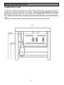
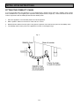
FREE STANDING
ELECTRIC COOKER
WITH GAS HOB
ZCM 1000X
INSTRUCTION BOOKLET
IMPORTANT SAFETY INFORMATION
These warnings are provided in the interests of your safety. Ensure that you understand them all before installing
or using the appliance. Your safety is of paramount importance. If you are unsure about any of the information in
this book contact the Customer Care Department. Telephone 0870 5 727727.
·
INSTALLATION
·
The appliance must be installed according to the
instructions supplied. The installation work must
be undertaken by a competent person as stated
in the Gas Safety (Installation & Use) regulations
current edition.
·
It is important that the appliance is suitable for
your gas supply. Your installer should check the
rating plate.
·
·
The appliance must be
adequately ventilated room.
·
·
Please ensure that the floor the appliance is to
be installed upon is level.
·
This appliance is heavy and care must be taken
when moving it. Do not try to move the
appliance by pulling the door handle.
·
All packaging, both inside and outside the
appliance must be removed before the appliance
is used.
installed
in
·
·
an
·
Do not stand on the appliance or on the open
oven door.
·
Do not allow children to play with any part of the
packaging.
·
It is dangerous to alter the specifications or
modify the appliance in any way.
·
·
·
CLEANING AND MAINTENANCE
·
·
·
CHILD SAFETY
·
·
·
Ensure that the vents at the top of the oven are
not obstructed to ensure ventilation of the oven
cavity.
Never line any part of the appliance with foil.
Do not allow heatproof cooking material, e.g.
roasting bags to come into contact with oven
elements because they may catch fire.
Always stand back from the appliance when
opening the oven door to allow any build up of
steam or heat to release.
Do not place sealed cans or aerosols inside the
oven. They may explode if they are heated.
Ensure that all control knobs are in the OFF
position when not in use.
Do not stand on the open oven door.
Do not hang towels, dishcloths or clothes from
the appliance handle.
·
This appliance is designed to be operated by
adults. Young children must not be allowed to
tamper with the controls or play near or with the
appliance.
·
The appliance and accessible parts especially
around the grill area become hot when the
appliance is in use.
Do not leave cookware containing foodstuffs,
e.g. fat or oil in the appliance in case it is
inadvertently switched on.
This appliance should be kept clean at all times.
A build-up of fats or other foodstuffs could result
in a fire, especially in the grill pan.
Do not disconnect the appliance from the gas
supply if the supply pipe does not have a
bayonet connection as described in the
installation section. If this is the case contact the
person who installed the appliance.
Only clean this appliance in accordance with the
instructions given in these books.
Always switch off the electric supply before
cleaning the appliance.
AT THE END OF THE APPLIANCES LIFE
·
CAUTION: Accessible parts may be hot
when the grill is in use. Young children
should be kept away.
When the time comes to dispose of your
appliance please contact your local Council
Authority. They can arrange to dispose of the
appliance in a safe and controlled manner. The
number will be in the telephone book.
DURING USE
·
Do not use this appliance if it is in contact with
water. Never operate it with wet hands.
·
Take great care when heating fats and oils as
they will ignite if they become too hot.
·
When you are lighting any burner check that it is
lit before you leave the appliance. When turning
off a burner, do not leave the appliance until the
flame has gone out.
·
Please read the
instruction books
carefully before use and
retain for future reference.
To help you the following symbols will be found in
the book
Safety Instructions
Always use oven gloves to remove and place
food in the oven.
Hints and Tips
2
CONTENTS
FOR THE USER
Important Safety Information
2
Description of the Appliance
Rating Plates
4
5
Before Using the Appliance
Location
5
5
The Gas Hob
Uses of the Hob
To Light the Hob Burners
Things to Note
Hints & Tips
The Timber Surround
Accessories – Chopping board
Helpful Hints When Buying and Preparing Food
6
6
7
7
7
7
7
8
Care and Cleaning
Cleaning Materials
Cleaning the Hob
Cleaning the Hob Burner Parts and Pan Support
Hints & Tips
Replacing the Hob Burner Parts
Replacing the Pan Support
Care and Cleaning of the Wooden Surround
9
9
9
10
10
10
11
11
Something Not Working?
12
Service and Spare Parts
13
Guarantee Conditions
14
FOR THE INSTALLER
Technical Details
Warnings
Things to Note
Moving the Appliance
Safety Requirements / Ventilation
Location of Appliance
Connection to the Electricity Supply
Connecting to Gas
Fitting the Stability Chain
Pressure Testing
Notes
15
16
16
17
17
18
19
20
21
22
23
3
DESCRIPTION OF THE APPLIANCE
SLOT IN ELECTRIC COOKER WITH GAS HOB
The appliance contains a multifunction oven which comprises a number of different cooking functions and a full
width grill.
The gas hob with five burners is fitted with automatic ignition.
RATING PLATES
The Hob: This is situated on the underside of the right hand side of the hob, above the towel rail.
The Oven: This is situated on the front fame of the oven upon opening the door.
The appliance must be protected by a suitably rated fuse or circuit breaker. The rating of the appliance is given
on the rating plates.
Do not remove the rating plates from the appliance as this may invalidate the guarantee.
4
BEFORE USING THE APPLIANCE
IMPORTANT
Please read both this and the
accompanying ZBM 799 Instruction Book
before installing or using this appliance
and retain for future reference.
Should the appliance be sold or transferred, always
ensure that the book is left with the appliance in
order that the new owners can get to know the
functions of the new appliance and the relevant
warnings.
FOR OPERATING INSTRUCTIONS ON THE USE
AND INSTALLATION OF THE OVEN PLEASE
REFER TO THE ZBM 799 INSTRUCTION BOOK.
LOCATION
The room the appliance is fitted in must
have a good air supply that meets the
standard BS 5440 Part 2 (current edition).
The appliance may be placed in a
kitchen, kitchen/diner or bedsit but not in
a garage. It should not be installed in a
3
bedsit smaller than 20m .
The use of a gas cooking appliance results in the
production of heat and moisture in the room in which
it is installed. Ensure that the kitchen is well
ventilated: keep natural ventilation holes open or
install a mechanical ventilation device (mechanical
extractor hood).
Prolonged intensive use of the appliance may call for
additional ventilation, for example opening of a
window, or more effective ventilation, for example
increasing the level of mechanical ventilation where
present.
5
THE GAS HOB
USES OF THE HOB
The gas hob has four different burner sizes to suit
different types of cooking:
To ensure maximum burner efficiency only use pots
and pans with flat bases appropriate to the burner
size used.
Burner
Ultra Rapid
Rapid
Normal
Simmer
Minimum
Pan Size
160mm (6½”)
120mm (5”)
120mm (5”)
120mm (5”)
Maximum
Pan Size
300m (11½”)
200mm (8”)
200mm (8”)
200mm (8”)
Ensure the pan support is correctly fitted
before using the hob. See page 11.
HOW TO LIGHT THE HOB BURNERS
The hob ignition works by means of an electric spark
system. Details about the plug are given on page
22.
1. Push in and turn the control knob to the left to the
highest setting. This is shown by a large flame
symbol.
2. When the burner has lit release the control and
adjust the setting as required.
When lighting any burner ensure that it is
lit before you leave the appliance.
When turning off a burner, ensure the
flame has gone out before leaving the
appliance.
TO TURN OFF ANY BURNER
1. Turn the control knob to the off position.
This is shown by a large dot.
Place pans on the centre of the burners.
Position pans so the handles cannot be
accidentally knocked or overhang the
appliance.
Lift pans on and off the pan supports. Do
not slide them across the hob.
6
THINGS TO NOTE
·
THE TIMBER SURROUND
If you are having any difficulty lighting a hob
burner turn all the hob controls off and make
sure the burner parts have been replaced
correctly.
See page 11 for more information.
·
There will be some pattern, colour and grain
differences over the timber surfaces. This is a
normal characteristic of the appearance of
wooden products.
·
Please note that timber surfaces will weather
over time as they are exposed to light.
HINTS AND TIPS
·
Keep flames under the base of pans. If the
flames lick round the sides of the pan you are
wasting gas.
·
Timber surfaces should be wiped down with a
sparing amount of water.
·
·
Do not overfill pans or they will boil over.
·
Water should never be left to stand on wooden
surfaces for any period of time.
·
Do not use pans with very heavy handles which
cause the pan to tip.
ACCESSORIES
·
Cover pans with a lid whenever possible. Food
will heat up more quickly and there will be less
steam in the kitchen.
CHOPPING BOARD
Use pans with flat bases. They are more stable
than a pan which is warped.
Do not leave accidental spillage on the
hob or removable parts. The spillage
should be wiped up and the parts washed
and carefully dried as soon as the hob,
pan supports and burner parts are cool
enough to touch.
See pages 9 and 10 for full cleaning
instructions.
·
A flat based Wok will stand stable on the pan
supports. If you use a round based Wok with a
collar support, the collar must be the open
wirework type otherwise the performance of the
burner will be affected.
Take care to avoid burns and scalds when
reaching across the hotplate.
Take extra care when deep fat frying, do
not cover the pan with a lid. Do not leave
a pan unattended. If the pan catches fire,
leave it where it is and turn off all controls.
Place a damp cloth or a fitting lid over the
pan to smother the flames. Never put
water on the fire. Leave to cool for 30
minutes.
For the operating instructions on
the use of the oven please refer to
the ZBM 799 Instruction Book.
7
·
Always remove the chopping board when the
hob is in use.
·
Always keep wooden kitchen utensils well away
from naked flames.
·
Dry the chopping board thoroughly before
storage.
·
In the kitchen keep worktops, chopping boards
and utensils clean with soapy water between
preparation stages. Ideally, keep one chopping
board for raw meat and another for other foods.
Keep your dish cloths and tea towels clean.
·
The chopping board is not covered by the
guarantee
conditions
accompanying
this
appliance.
HELPFUL HINTS WHEN BUYING AND PREPARING FOOD
Care must be taken when handling foods in the
home. Always follow the basic rules of food hygiene
to prevent bacterial and microbial growth and cross
contamination when preparing, reheating, cooking,
cooling, defrosting and freezing foods.
11. If not eaten straight away after cooking, food
should be cooled as quickly as possible (within
one hour) and then refrigerated or frozen as
required. Do not put hot food into a refrigerator
or freezer.
1. Always ensure food you purchase is of good
quality and in prime condition. Shop at a reliable
source and buy the ‘freshest’ looking package –
avoid shop worn labels or produce covered in
dust.
12. In the kitchen keep worktops, chopping boards
and utensils clean with hot soapy water
between preparation stages. Ideally, keep one
chopping board for raw meat and another for
other foods. Keep your dish cloths and tea
towels clean.
2. Avoid buying chilled or frozen products if you
cannot store them straight away. The use of an
insulated container when shopping is advisable.
3. Buy and consume foods prior to the ‘Sell by’ or
‘Best Before’ date.
4. When you arrive home, place perishable foods
in the refrigerator or freezer immediately. Ensure
they are well covered to prevent cross
contamination with bacteria from raw to cooked
foods.
5. Follow the cooking instructions on packets of
prepacked and cooked chilled foods, but be
prepared to adjust cooking times and
temperatures to suit your particular oven. For
example, the Fan Oven generally requires 2025°C lower temperature than conventional
ovens.
6. Always ensure that cooked chilled foods are
thoroughly reheated until they are piping hot
throughout.
7. It is preferable to defrost frozen foods slowly in
the refrigerator. Alternatively, a microwave
cooker or the Defrost function on your oven may
be used.
8. Always cook defrosted foods immediately after
thawing. Thawed food should never be refrozen.
9. Joints of meat and poultry should be thoroughly
defrosted before cooking.
10. Cook meat thoroughly – use a meat thermometer
if preferred, which penetrates the joint to check
that the centre temperature has reached the
required temperature (see table below).
MEAT
TEMPERATURES
Beef
Rare - 60°C
Medium - 70°C
Well Done - 80°C
Pork
Well Done - 80°C
Lamb
Medium - 70°C
Well Done - 80°C
8
CARE AND CLEANING
For hygiene and safety reasons you must
keep this cooker clean. A build up of fat
or other foodstuff could cause a fire.
Before cleaning the cooker always ensure
the cooker is cool before switching off the
supply.
Do not use any polishes, caustic cleaners,
abrasives, washing soda or soap powder except
those recommended in this book.
If you own a dishwasher please read the operating
instructions for the machine before you wash any
part of your appliance in it.
Clean the appliance regularly using a cloth that has
been wrung out in hot water to which a little washing
up liquid has been added. Rinse and polish with a
soft cloth.
Do not attempt to remove any of the control
knobs from the hob as this may cause
damage and is a safety hazard.
CLEANING MATERIALS
Before using any cleaning materials on your
appliance, check that they are suitable and that their
use is recommended by the manufacturer.
Cleaners that contain bleach should NOT be used
as they may dull the surface finishes. Harsh
abrasives should also be avoided.
CLEANING THE HOB
Switch off the electricity supply before cleaning and
ensure the hob is cool.
Clean the hob with a soft cloth and hot water to
which a little washing up liquid has been added.
Any spillages on the Stainless Steel finish must be
wiped off immediately. Cleaners that contain bleach
should NOT be used as they may dull the surface
finishes. Abrasives must also be avoided to prevent
damaging the Stainless Steel or painted finishes. To
prevent streaking on Stainless Steel models finish
with a soft cloth.
Ensure the hob is dry before replacing any parts
removed for cleaning.
9
CLEANING THE HOB BURNER PARTS
AND PAN SUPPORT
Take care not to damage the spark
electrodes. If damaged they will not light.
Please note that due to the nature of stainless
steel the pan support will tarnish through use over
a period of time. Some of this discolouration may
be removed by using proprietary cleaning agents.
Remove the burner parts carefully taking care not
to damage the spark electrodes. Clean the pan
support, burner caps and burner crowns in hot
water to which a little washing up liquid has been
added. You may use mild abrasives.
Do not wash the pan support or burner
parts in a dishwasher.
Make sure the slots in the crown are not blocked
by food or cleaning materials. If you look after the
burner crowns in this way they will stay reasonably
clean, however, the surface will dull with time.
Aluminium pans can leave shiny metal marks on
the pan supports. Reduce the marking by regularly
cleaning the pan supports and ensuring the bases
of new pans are well scrubbed to remove loose
deposits.
After cleaning the burner parts and pan
supports dry them thoroughly before replacing.
HINTS AND TIPS
·
If food spills during cooking move the pan to
another burner to finish cooking. Then the soiled
parts can be cleaned as soon as they are cool
enough and before the spill burns on.
Do not leave accidental spillage on the hob
or removable parts. The spillage should
be wiped up and the parts washed and
carefully dried as soon as the hob, pan
support and burner parts are cool enough
to touch.
·
Clean the wells of the burner body if spillage has
entered when the hob has cooled.
10
REPLACING THE HOB BURNER PARTS
1. Crown to burner body
Do not force the crown on to the burner body.
Make sure the hole in the crown is over the
electrode. Check that the location pegs sit in the
slots in the body. Check that the crown can be
moved slightly from side to side.
2. Cap to crown
Place the burner cap centrally on top of the
crown with the enamel side up. Move sideways
and front to back to check the cap is properly
fitted.
3. Check for ignition
If a burner will not light, check the crown and cap
positions.
REPLACING THE ULTRA RAPID BURNER
CAP
The Ultra Rapid burner cap is in two parts.
1. Ensure the aluminium part is fitted correctly
before placing the enamelled cap in the same
orientation on top.
2. Move the cap sideways and front to back to
check the cap is properly fitted.
TO REPLACE THE PAN SUPPORT
1. Position the location pegs on the pan support
over the location points on the hotplate and
gently ease the pan support into place.
Ensure the pan support has been carefully
dried and is correctly fitted before use.
CARE AND CLEANING THE WOODEN
SURROUND OF THE APPLIANCE
·
Clean timber surfaces with a sparing amount of
warm water, a drop of washing up liquid and a
well wrung cloth.
·
Always mop up spills of water and other liquids
straight away. Do not allow liquids to stand on
wooden surfaces for any period of time.
CLEANING THE
FURNITURE
OVEN
AND
OVEN
For cleaning instructions relating to the oven and its
furniture please refer to the ZBM 799 Instruction
Book.
11
SOMETHING NOT WORKING?
Please carry out the following checks on your appliance before calling a Service Engineer. It may be that the
problem is a simple one which you can solve yourself without the expense of a service call.
If our Service Engineer finds that the problem is listed below you will be charged for the call whether or not the
appliance is under guarantee.
Please note that it will be necessary to provide proof of purchase for any in-guarantee service calls.
PROBLEM
POSSIBLE SOLUTION
For problems relating to the oven please refer to the ZBM 799 operating instructions.
The hob burners will not light
Ensure the burner parts have been placed correctly.
See page 11.
Check that there is not a problem with your gas supply.
You can do this by making sure that other gas
appliances such as central heating or gas fire are
working.
Having difficulty cleaning any part of the hob
Check that the instructions for care and cleaning
beginning on page 9 are being followed.
12
SERVICE AND SPARE PARTS
In the event of your appliance requiring service, or if you wish to purchase spare parts, please contact your local
Service Force Centre by telephoning:-
0870 5 929929
Your telephone call will be automatically routed to the Service Force Centre covering your post code area.
For the address of your local Service Force Centre and further information about Service Force, please visit the
website at www.serviceforce.co.uk
Before calling out an engineer, please ensure you have read the details under the heading "Something Not
Working?".
When you contact the Service Force Centre you will need to give the following details:
1. Your name, address and post code.
2. Your telephone number.
3. Clear and concise details of the fault.
4. The model and serial number of the appliance (found on the rating plate).
5. The purchase date.
Please note that a valid purchase receipt or guarantee documentation is required for in-guarantee service
calls.
CUSTOMER CARE DEPARTMENT
For general enquires concerning your Zanussi appliance, or for further information on Zanussi products, please
contact our Customer Care Department by letter or telephone at the address below or visit our website at
www.zanussi.co.uk
Customer Care Department
Zanussi
55 – 77 High Street
Slough
Berkshire
SL1 1DZ
0870 5 727727 (*)
*calls to this number may be recorded for training purposes.
13
GUARANTEE CONDITIONS
STANDARD GUARANTEE CONDITIONS
We, Zanussi, undertake that if within 12 months of the date of the purchase this Zanussi appliance or any part
thereof is proved to be defective by reason only of faulty workmanship or materials, we will, at our option repair or
replace the same FREE OF CHARGE for labour, materials or carriage on condition that:
·
·
The appliance has been correctly installed and used only on the electricity supply stated on the rating plate.
·
The appliance has not been serviced, maintained, repaired, taken apart or tampered with by any person not
authorised by us.
·
·
·
All service work under this guarantee must be undertaken by a Zanussi service centre.
The appliance has been used for normal domestic purposes only, and in accordance with the manufacturer’s
instructions.
Any appliance or defective part replaced shall become the Company’s property.
This guarantee is in addition to your statutory and other legal rights.
Home visits are made between 8.30am and 5.30am Monday to Friday. Visits may be available outside these
hours in which case a premium will be charged.
Exclusions
This guarantee does not cover:
·
Damage or calls resulting from transportation, improper use or neglect, the replacement of any light bulbs or
removable parts of glass or plastic.
·
Costs incurred for calls to put right an appliance which is improperly installed or calls to appliances outside the
United Kingdom.
·
Appliances found to be in use within a commercial environment, plus those which are subject to rental
agreements.
·
Products of Zanussi manufacture which are not marketed by Zanussi.
14
TECHNICAL DETAILS
Loading info : Gas hotplate
L.H.F. – Simmer Injector marking
Natural gas
1.0 Kw ( 3412 Btu/h )
070
L.H.R. / R.H.R. – NormalInjector marking
1.8 Kw ( 6142 Btu/h )
096
R.H.F. – Rapid Injector marking
2.8 Kw ( 9554 Btu/h )
119
Centre. – Ultra Rapid Injector marking
3.5Kw ( 11942 Btu/h )
136
Physical Characteristics –
Height:
940 mm
Width:
1050 mm
Depth:
(excluding handles)
600 mm
Weight:
100 Kg Net
Gas connection
:-
Electrical connection :-
GAS CATERGORY
Rear right hand side of appliance at hotplate level
Rc ½ (½” B.S.P. female )
230 / 240 V 50 Hz mains 3 cable is supplied with an integral, moulded plug fitted
with a 3 amp fuse.
COUNTRIES OF DESTINATION
CAT. I2H
GB, IE
CAT. I3+
GB, IE
This appliance complies with: European Council Directive 73/23/EEC.
EMC Directive 89/336/EEC.
CE Marking Directive 93/68/EEC.
15
INSTALLATION INSTRUCTIONS
For Instructions relating to the oven please refer to the ZBM 799
Instruction Book
WARNINGS
·
This appliance must be installed by a qualified electrician/competent person (CORGI Registered).
Safety may be impaired if installation is not carried out in accordance with these instructions.
·
Before connecting the appliance make sure that the voltage of your electricity supply is the same as that
indicated on the rating plate. The rating plate can be seen by opening the oven door.
·
Do not alter the electrical circuitry of this appliance.
Warning: This appliance must be earthed.
THINGS TO NOTE
·
When fitting this appliance the recommended dimensions as shown in Fig. 1 and the instructions on ‘Location
of appliance’ must be followed.
·
Enquiries regarding the installation of the cooker point if required should be made to your Regional Electricity
Company to ensure compliance with their regulations.
·
The cooker point should be within 2m of the appliance to make it accessible to switch off the appliance in
case of an emergency.
NOTE: HOUSE CIRCUIT
Earth leakage / continuity tests must be carried out before the appliance is connected to the mains supply and
rechecked after fitting.
16
INSTALLATION INSTRUCTIONS
MOVING THE APPLIANCE
You may damage some soft or badly fitted floor
coverings when you move the appliance. The floor
coverings under the appliance should be securely
fixed so it does not ruck up when you move the
appliance across it.
Two people may be required to move the appliance.
1. Remove all oven furniture.
2. Close the oven door.
3. Lift the appliance by holding the bottom of the
wooden side panels.
4. This appliance is heavy and care must be taken
when moving it. Do not try to move the
appliance by the pulling the door handle.
IMPORTANT – SAFETY REQUIREMENTS
This appliance must be installed in accordance with the Gas Safety (Installation and Use) Regulations Current
Editions and the I.E.E. Wiring Regulations. Detailed recommendations are contained in the following British
Standard Codes of Practice – BS.6172, BS.5440: Part 2 and B.S.6891. All British Standards must be ‘Current
Editions’.
PROVISION FOR VENTILATION
This appliance is not connected to a combustion products evacuation device. It shall be installed and connected
in accordance with the current installation regulations. Particular attention shall be given to the relevant
requirements regarding ventilation.
The room containing the appliance should have an air supply in accordance with BS.5440: Part 2 Current Edition.
All rooms require an openable window or equivalent and some rooms will require a permanent vent as well. For
3
2
3
3
room volumes up to 5m an air vent of 100cm is required: for room volumes between 5m and 10m an air vent of
2
50cm is required. If the room has a door that opens directly to the outside, no air vent is required. For room
3
volumes that exceed 11m no air vent is required. If there are other fuel burning appliances in the same room,
BS.5440: Part 2 Current Edition should be consulted to determine the requisite air vent requirements.
Prolonged intensive use of the appliance may call for additional ventilation, for example opening a window, or
more effective ventilation, for example increasing the level of mechanical ventilation where present.
17
INSTALLATION INSTRUCTIONS
LOCATION OF APPLIANCE
This appliance is not for commercial use and must only be installed in domestic premises.
3
This appliance must not be installed in a bed-sitting room of volume less than 20m or in a bathroom, shower or
garage. This is a type ‘X’ appliance, it is essential that the appliance is positioned as stated below i.e. shelves,
wall cabinets and cooker hoods must be fitted a minimum of 750mm directly above the top of the hotplate (or
greater for cooker hoods if recommended by manufacturers instructions) and 400mm above the hotplate when
fitted in line with the outside of the appliance. If the units are intended to be fitted adjacent to the appliance but
less than 400mm above the hotplate, then a minimum space of 100mm must be maintained between the sides of
the unit and the appliance. The hotplate must be a minimum of 5mm above the height of adjacent units. Curtains
must not be fitted immediately behind the appliance or within 150mm of the sides of the hotplate. If fitted next to
or between two base units a minimum space of 1mm must be left between each unit and the sides of the
appliance.
Fig 1
18
INSTALLATION INSTRUCTIONS
CONNECTING TO THE
ELECTRICITY SUPPLY
WARNING: THIS APPLIANCE MUST BE EARTHED.
DO NOT EARTH THIS APPLIANCE TO THE GAS
SUPPLY PIPING.
This appliance must be connected to 230V-240V
A.C. 50Hz supply. It is supplied with 2 metres of 5
amp 3 core cable incorporating a moulded 13 amp
plug, fitted with a 3 amp fuse, which can be plugged
directly into the nearest suitable socket. If this is not
long enough, the supply cable can be replaced
2
totally by a longer cable at least 0.75mm nominal
cross sectional area (24/0.2mm). Ensure the plug is
accessible to the user.
IF THE MOULDED PLUG IS CUT FROM THE
CABLE FOR ANY REASON, IT MUST BE
DESTROYED OR DISPOSED OF SAFELY, AS
THE PROTRUDING WIRES WILL BE AN
ELECTRIC SHOCK HAZARD.
If any other type of plug is used it should incorporate
a 3 amp fuse in either the plug or adapter or at the
distribution board.
If the cable has to be threaded through small
apertures in cabinets etc., it may be disconnected
from the appliance, then re-connected to as shown
in Fig.2.
Fig.2
DO NOT EXTEND THE CABLE USING PLASTIC
OR CERAMIC CONNECTION TERMINAL BLOCKS
AND/OR INSULATION TAPE.
ALL EXTERNAL WIRING BETWEEN THE
APPLIANCE AND THE ELECTRICAL SUPPLY
SHALL
COMPLY
WITH
I.E.E.
WIRING
REGULATIONS.
If the wiring is extended or a completely new cable
fitted a 3-pin 13 amp plug should be fitted. (See Fig.
2a). Connect the wires as follows:
BROWN to the Live Terminal.
BLUE to the Neutral Terminal.
GREEN and YELLOW to the Earth Terminal.
As the colours of the wires in the mains lead which
you fit may not correspond with the coloured
markings identifying the terminals in your plug,
proceed as follows:
The wire which is GREEN and YELLOW must be
connected to the terminal in the plug which is
marked with the letter ‘E’ or by the earth symbol
or coloured GREEN or GREEN and YELLOW.
The wire which is coloured BLUE must be connected
to the terminal which is marked with the letter ‘N’ or
coloured BLACK.
The wire which is coloured BROWN must be
connected to the terminal which is marked with the
letter ‘L’ or coloured RED.
Fig. 2a
FIT A 3 AMP FUSE TO THE PLUG HOLDER.
Ensure that the supply cable cannot get caught by
the stability chain. Plug in the appliance.
19
INSTALLATION INSTRUCTIONS
CONNECTING TO GAS
This appliance is designed to be installed with an appliance flexible connection only. Supply piping should not be
3
less than R /8. Connection is made to the Rc ½ (½” B>S>P>) female threaded entry pipe located just below the
hotplate level on the rear left hand side of the appliance. NOTE: ONLY LIQUID SEALANTS TO BE USED
WHEN INLET GAS PIPE IS FITTED I.E.: DO NOT USE P.T.F.E. SEALANT TAPE. Check for gas soundness
after connecting to the gas supply. The gas bayonet connector must be fitted in the shaded area indicated in
Fg.3. Take into account that it must be possible to pull the appliance forward sufficiently. The hose must not get
caught.
IMPORTANT: FLEXIBLE TUBING USED MUST COMPLY WITH BS.669 CURRENT EDITION.
Fig. 3
20
INSTALLATION INSTRUCTIONS
FITTING THE STABILITY CHAIN
It is recommended that if the appliance is to be installed with a flexible supply pipe that a stability chain is fitted
and is available from your supplier (see Important Safety Requirements, Page 20). These instructions should be
read in conjunction with the leaflet packed with the stability chain.
1. Place the appliance in its intended position and level appliance.
2. Mark a position 100mm in from the to of the rear R.H. corner.
3. Measure down 150mm from this point. This gives the position of the wall anchor point for the stability chain.
4. The stability chain anchor point on the appliance is shown in the diagram fig 4.
Fig. 4
21
INSTALLATION INSTRUCTIONS
PRESSURE TESTING
1. The rapid injector is used as a pressure test point.
2. Connect the pressure gauge to the Rapid injector.
3. Check the supply pressure by turning the Rapid burner on and one other hotplate burner full on and light the
appropriate burner. The pressure should be :(i) for natural gas 20mbar.
4. Turn off the taps, disconnect the pressure gauge.
5. Check operation of each hotplate burner.
CHECKING THE HOTPLATE
Fit the burner crowns and caps ensuring that they are correctly seated. Fit the pan support. Check each of the
hotplate burners in turn by turning the hotplate to its full position and holding the knob depressed. As soon as the
burners are lit the knob can be released.
GENERAL NOTE
Instruct the user how to use the appliance and its ignition system. Refer the user to the wording in the inside
cover which gives advice on the safe operation of the appliance.
22
NOTES
23
IMPORTANT NOTICE
In line with our continuing policy of research and development, we reserve the right to alter models and
specifications without prior notice.
This instruction booklet is accurate at the date of printing, but will be superseded if specifications or appearance
are changed.
ZANUSSI
55 – 77 HIGH STREET,
SLOUGH,
BERKSHIRE,
SL1 1DZ
TELEPHONE 0870 5 727727
www.zanussi.co.uk
Part Number: 311546001
© Electrolux Household Appliances Limited 2002