1
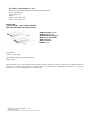
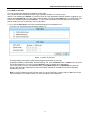
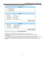
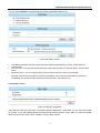
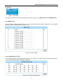
FSW-2104W
4-Port Media Streaming
Plus 1 Fiber Port Switch
LEGAL
The information in this publication has been carefully checked and is believed to be entirely accurate at the time of
publication. CTC Union Technologies assumes no responsibility, however, for possible errors or omissions, or for any
consequences resulting from the use of the information contained herein. CTC Union Technologies reserves the right to
make changes in its products or product specifications with the intent to improve function or design at any time and
without notice and is not required to update this documentation to reflect such changes.
CTC Union Technologies makes no warranty, representation, or guarantee regarding the suitability of its products for any
particular purpose, nor does CTC Union assume any liability arising out of the application or use of any product and
specifically disclaims any and all liability, including without limitation any consequential or incidental damages.
CTC Union products are not designed, intended, or authorized for use in systems or applications intended to support or
sustain life, or for any other application in which the failure of the product could create a situation where personal injury
or death may occur. Should the Buyer purchase or use a CTC Union product for any such unintended or unauthorized
application, the Buyer shall indemnify and hold CTC Union Technologies and its officers, employees, subsidiaries,
affiliates, and distributors harmless against all claims, costs, damages, expenses, and reasonable attorney fees arising out
of, either directly or indirectly, any claim of personal injury or death that may be associated with such unintended or
unauthorized use, even if such claim alleges that CTC Union Technologies was negligent regarding the design or
manufacture of said product.
TRADEMARKS
Microsoft is a registered trademark of Microsoft Corp.
FCC Notice:
This equipment has been tested and found to comply with the limits for a Class B digital device, pursuant to Part 15 of
the FCC Rules. These limits are designed to provide reasonable protection against harmful interference when the
equipment is operated in a residential environment. This equipment generates, uses, and can radiate radio frequency
energy and if not installed and used in accordance with the instruction manual may cause harmful interference in which
case the user will be required to correct the interference at his own expense. NOTICE: (1) The changes or modifications
not expressively approved by the party responsible for compliance could void the user's authority to operate the
equipment. (2) Shielded interface cables and AC power cord, if any, must be used in order to comply with the emission
limits.
CISPR PUB.22 Class B COMPLIANCE:
This device complies with EMC directive of the European Community and meets or exceeds the following technical
standard. EN 55022 - Limits and Methods of Measurement of Radio Interference Characteristics of Information
Technology Equipment. This device complies with CISPR Class B.
CE NOTICE
Marking by the symbol CE indicates compliance of this equipment to the EMC directive of the European Community.
Such marking is indicative that this equipment meets or exceeds the following technical standards: EN
55022:1994/A1:1995/A2:1997 Class A and EN61000-3-2:1995, EN61000-3-3:1995 and EN50082-1:1997
CTC Union Technologies Co., Ltd.
Far Eastern Vienna Technology Center (Neihu Technology Park)
8F, No. 60, Zhouzi St.
Neihu, Taipei, 114
Taiwan
Phone: +886-2-2659-1021
FAX: +886-2-2799-1355
FSW-2104W
4-port 10/100M + 1-port 100Base-FX WAN
Web Smart Media Streaming Fiber Switch
* IGMP Snooping v1 / v2
* IGMP Proxy v1 / v2
* Web-Based Management
* Built-in wire speed NAT
* QoS Functions
* DHCP solutions
*SNMP v1 / v2
User Manual
Version 1.0 July 2009
This manual supports the following models:
FSW-2104W
This document is the current official release manual. Please check CTC Union's website for any updated manual or
contact us by E-mail at [email protected]. Please address any comments for improving this manual or to point out
omissions or errors to [email protected]. Thank you.
©2009 CTC Union Technologies Co.,Ltd.
All Rights Reserved
The contents of this document are subject to change without any prior notice.
Contents
Chapter 1: About This Guide ................................................................................................. 7
Chapter 2: Introduction .............................................................................................................. 7
2.1 Product Description...................................................................................................... 7
2.2 Product Features........................................................................................................... 7
Chapter 3: Connecting to Router............................................................................................. 9
3.1 System Requirements.................................................................................................. 9
3.2 Installation Environment Requirements.................................................................. 9
3.3 Connecting the Router................................................................................................. 9
Chapter 4: Fast Installation and Configuration.................................................................... 9
4.1 TCP/IP Configuration.................................................................................................... 9
Chapter 5: Configuring the Router........................................................................................ 11
5.1 login ................................................................................................................................ 11
5.2 Status ............................................................................................................................. 11
5.3 LAN ................................................................................................................................. 12
5.4 WAN ................................................................................................................................ 14
5.5 NAT ................................................................................................................................. 18
5.6 Firewall........................................................................................................................... 19
5.7 QoS ................................................................................................................................. 20
5.8 IGMP ............................................................................................................................... 21
5.9 SNMP .............................................................................................................................. 22
5.10 SNTP............................................................................................................................. 23
5.11 VLAN Configuration ................................................................................................. 24
5.12 Port Configurations .................................................................................................. 24
5.13 Storm Control............................................................................................................. 25
5.14 Tool ............................................................................................................................... 26
5.15 System Logs............................................................................................................... 28
Appendix A: Glossary............................................................................................................... 30
FSW-2104W Multimedia Residential Gateway
Chapter 1: About This Guide
Thank you for choosing the FSW-2104W FTTx Router.
This router provides dedicate solutions for Fiber to the Home networks for Triple-Play service.
To connecting your local network can share Internet access, files and fun for multiple PCs through one ISP
account. It is an easy, web-based setup for installation and management. This guide will configure the router
easy. Before installing the router, please look through this guide to get to know all the router’s functions.
Chapter 2: Introduction
2.1 Product Description
The FSW-2104W is a 4-port Web Smart switch with 1-port wire speed NAT-router. Its designed is dedicated to
IPTV Home Gateway network solutions. The FSW-2104W is intended for Multimedia applications in the Digital
Home, it supports the IGMP proxy,IGMP Snooping V1/V2 function, QoS function and wire speed NAT function.
The FSW-2104W provides flexible access control .It has built-in NAT and DHCP server supporting static IP
address distributing. It supports Virtual Server and DMZ host for Port Triggering needs, and remote
management and log so that network administrators can manage and monitor the network on real time. Support
Storm control Suppression. The priority features by IP Diffserv Application-Based of packets.
2.2 Product Features
•
•
•
•
•
•
•
•
•
•
•
•
•
•
•
•
•
•
•
•
•
Complies with IEEE802.3, IEEE802.3u standards.
Built in 4-port 10M/100M auto-detect Half/Full duplex switch ports with TX interfaces.
Ethernet connection to WAN by fiber, 100Base-FX.
For WAN port, support static IP, dynamic IP (DHCP client), PPPOE.
Built-in wired speed 200Mbps NAT.
DHCP server supports static IP address distributing.
Supports MAC address auto-learning and auto-aging.
Supports up to 2K Unicast addresses.
Priority features by IP Diffserv Application-Based of packets.
Four queues per port for QoS. The Priority Queue be set at WRR (Weighted Round Robin) assigns
guaranteed bandwidth to a queue.
Broadcast/Multicast/Un-learned Unicast Storm Suppression.
IGMP Snooping v1/v2.
SNMP v1/v2.
Access control to LAN connection.
WAN IP filtering, Mac filtering.
Dynamic routing and 3 static routing entries.
Web-Based management.
Supports firmware upgrade, automatic firmware upgrade.
LED indicators for monitoring power, link, activity, speed mode.
Plastic case, desktop or wall-mounting design
External Power Adapter supply
7
FSW-2104W Multimedia Residential Gateway
2.3 Product Specifications
IEEE802.3 10Base-T,
IEEE802.3u 100Base-TX, 100Base-FX
Topology
Star
CSMA/CD,DHCP, TCP/IP、PPPoE、DHCP、NAT、ICMP、SNTP、
Protocol
IGMP
Ethernet: 10Mbps (Half Duplex), 20Mbps (Full Duplex)
Data Transfer Rate
Fast Ethernet: 100Mbps (Half Duplex), 200Mbps (Full Duplex)
10Base-T: UTP category 3, 4, 5 cable (maximum 100m)
EIA/TIA-568 100Ù STP (maximum 100m)
Network Media (Cable)
100Base-Tx: UTP category 5, 5e cable (maximum 100m)
EIA/TIA-568 100Ù STP (maximum 100m)
One 100Base-FX port. (Duplex SC or BiDi SC)
Number of Ports
Four 10/100M Auto-Negotiation LAN RJ45 ports supporting Auto
MDI/MDIX
LED indicators
Power, Link/Act
Transfer Method
Store-and-Forward
MAC Address Learning
Automatically learning, automatically Update
Frame Filtering & Forward Rate 10Mbps: 14880pps, 100Mbps: 148800pps
Power Adaptor
DC 5V 2A
Dimensions (W×D×H)
150*95*32(mm)
Operating Temperature: 0 C~40 C (32 F~104 F)
Storage Temperature: -40 C~70 C (-40 F~158 F)
Environment
Operating Humidity: 10%~90% non-condensing
Storage humidity: 5%~95% non-condensing
Standards
8
FSW-2104W Multimedia Residential Gateway
Chapter 3: Connecting to Router
3.1 System Requirements
•
•
•
•
Broadband Internet Access Service (FTTx)
One single mode fiber connection using dual fiber or single fiber (WDM)
Each PC on the LAN needs a working Ethernet Adapter and an Ethernet cable with RJ45 connectors
TCP/IP protocol must be installed on each PC
3.2 Installation Environment Requirements
•
•
•
•
•
Not in direct sunlight or near a heater or heating vent
Not cluttered or crowded. There should be at least 2 inches (5 cm) of clear space on all sides of the router
Well ventilated (especially if it is in a closet)
Operating temperature: 0°~40°C (32°~104°F)
Operating Humidity: 10%~90%RH, Non-condensing
3.3 Connecting the Router
Please install the router according to the following steps.
Please pull out the power plug and keep your hands dry.
Steps:
1. Power off your PC(s) and the router.
2. Connect the PC(s) and all Switches/Hubs on your LAN to the LAN Ports on the router.
3. Connect the fiber from provider to fiber WAN port on the router.
4. Connect the AC power adapter to the AC power socket on the router, and the other side into an electrical
outlet. The router will start to work automatically.
5. Power on your PC(s) and Cable/DSL modem.
Chapter 4: Fast Installation and Configuration
This chapter describes how to configure the basic functions of your FSW-2104W Cable/DSL router. You may
access the Internet via the router immediately after it has been successfully configured.
4.1 TCP/IP Configuration
•
•
The default IP address of the FSW-2104W Cable/DSL Router is 192.168.123.211, and the default Subnet
Mask is 255.255.255.0. These values can be seen from the LAN, and can be changed as your desire.
Connect the local PCs to the LAN ports on the router. There are then two means to configure the IP address
for your PCs.
Configure the IP address manually
•
1) Set up the TCP/IP Protocol for your PC(s).
2) Configure the network parameters. The IP address is 192.168.123.xxx ("xxx" is from 1 to 254 except 211),
Subnet Mask is 255.255.255.0, and Gateway is 192.168.1.211(The router's default IP address)
Obtain an IP address automatically
•
1) Set up the TCP/IP Protocol in "Obtain an IP address automatically" mode on
your PC(s).
2) Power off the router and PC(s). Then turn on the router, and restart the PC(s).
The built-in DHCP server will assign IP addresses for the PC(s).You can run the Ping command in the
command prompt to verify the network connection between your PC(s) and the router.
The following example is under Windows XP environment:
Open a command prompt, and type ping 192.168.123.252, press Enter.
9
FSW-2104W Multimedia Residential Gateway
Figure 4-1 Successful result of Ping command
If the result displayed is same as to what is shown in figure 4-1, the connection between your PC and the router
has been established.
Figure 4-2 Fail result of ping command
If the result displayed is similar to what shown in figure 4-2, it means that your PC has not connected to the
router. If so, refer to the following steps for a solution.
1. Is the connection between your PC and the router correct?
Note: The Link/Act LEDs of LAN port on the router and LEDs on your PC's adapter should be lit.
2. Is the TCP/IP configuration for your PC correct?
Note: If the router's IP address is 192.168.123.211, your PC's IP address must be within the range of
192.168.123.1 ~ 192.168.123.254 but not 192.168.123.211 which is the gateway’s IP.
10
FSW-2104W Multimedia Residential Gateway
Chapter 5: Configuring the Router
5.1 login
Enter the User name and password correctly and click OK button (shown in figure 5-1). After your successful
login, you can configure and manage the router.
There are fourteen main menus are: Status, LAN, WAN, NAT, Firewall, Qos, IGMP, SNMP, SNTP, VLAN
config, Port config, Storm Control, Tool, System Logs. On the right of the web-based utility, there are the
detailed explanations and instructions for the corresponding page. To apply any settings you have altered on the
page, please click the Save button.
Detailed explanations for each web page's key functions are showing below:
User
name
and
password : admin
Figure 5-1 login
5.2 Status
The Status page displays the router's current status and configuration.
5.2.1 Information
This field displays the system information, including Current Status, Working Time, Network Time, Hardware
Version, Firmware Version and Compile Date.
5.2.1.1 WAN Status
These parameters apply to the WAN port of the router, including Connected Type, Connected Status, IP
Address, Subnet Mask, WAN MAC, Gateway, Primary DNS, and Secondary DNS
If PPPoE is chosen as the WAN connection type, the Disconnect button will be shown here while you are
accessing the Internet. You can also cut the connection by clicking the button. If you have not connected to the
Internet, a Connect button will be shown, you can then establish the connection by clicking the button.
11
FSW-2104W Multimedia Residential Gateway
5.2.1.2 LAN Status
This field displays the current settings or information for the LAN, including the MAC address, IP address and
Subnet Mask.
Figure 5-2 Router Status
5.3 LAN
Figure 5-3 the LAN menu
There are two submenus under the LAN menu (shown in figure 5-3): LAN, DHCP Clients. Click any of them,
and you will be able to configure the corresponding function.
12
FSW-2104W Multimedia Residential Gateway
5.3.1 LAN
Please configure the IP parameters of the LAN on this page.
Figure 5-4 LAN Setup and DHCP Setup
•
•
•
•
•
•
•
•
IP Address - Enter the IP address of your router in dotted-decimal notation (factory default:
192.168.123.252).
Subnet Mask - An address code that determines the size of the network. Normally use 255.255.255.0 as the
subnet mask.
MAC Address - The physical address of the router, as seen from the LAN. The value can't be changed.
DHCP Server - Enable or Disable the DHCP server. If you disable the Server, you must have another DHCP
server within your network or else you must manually configure the computer.
IP PC Starting - This field specifies the first of the addresses in the IP address pool. 192.168.123.50 is the
default start address.
IP PC Ending - This field specifies the last of the addresses in the IP address pool. 192.168.123.100 is the
default end address.
IP Lease Time - The IP Lease Time is the amount of time. A network user will be allowed connection to the
router with their current dynamic IP address.
Choose the time in box, which the user will be "leased" this dynamic IP address. The default value is 1 Day.
Note:
a. If you change the IP address of the LAN, you must use the new IP address to login to the router.
b. If the new LAN IP Address you set is not in the same subnet, the IP Address pool in the DHCP sever will not
take effect, until they are re-configured.
c. If the new LAN IP Address you set is not in the same subnet, the Virtual Server and DMZ Host may change
accordingly at the same time, you’d better re-configure it as well.
13
FSW-2104W Multimedia Residential Gateway
5.3.2 DHCP Clients
This page shows Host IP Address, Host IP Address for each DHCP Client attached to the router (figure
5-5):
Figure 5-5 DHCP Clients
•
•
•
NO. - The index of the DHCP Client
Host IP Address - The name of the DHCP client
Host MAC Address - The MAC address of the DHCP client
You cannot change any of the values on this page. To update this page and to show the current attached
devices, click on the Refresh button.
5.4 WAN
Figure 5-6 the WAN menu
There are two submenus under the LAN menu (shown in figure 5-6): WAN Connection, Bridge Convert. Click
any of them, and you will be able to configure the corresponding function. The detailed explanations for each
submenu are provided below.
14
FSW-2104W Multimedia Residential Gateway
5.4.1 WAN Connection
You can configure the WAN port parameters on this page.
First, please choose the WAN Connection Type (Dynamic IP/Static IP / PPPoE ) to the
Internet. The default type is PPPoE. If you aren’t given any login parameters (fixed IP address, logging ID, etc),
please select Dynamic IP. If you are given a fixed IP (static IP), please select Static IP. If you are given a user
name and a password, please select PPPoE. If you are not sure which connection type you use currently,
please contact your ISP to obtain the correct information.
1. If you choose Dynamic IP, the router will automatically get IP parameters from
your ISP. You can see the page as follows (figure 5-7):
Figure 5-7 WAN - Dynamic IP
This page displays the WAN IP parameters assigned dynamically by your ISP,
including IP address, Subnet Mask, Default Gateway, etc. Click the Renew button in Status menu to renew
the IP parameters from your ISP. Click the Release button to release the IP parameters.
If your ISP gives you one or two DNS addresses, select [DNS List] button in DNS Setup and enter the
primary and secondary addresses into the correct fields. Otherwise, the DNS servers will be assigned
dynamically from ISP.
Note: If you get ‘Address not found' errors when you go to a Web site, it is likely that your DNS servers are
set up improperly. You should contact your ISP to get DNS server addresses.
15
FSW-2104W Multimedia Residential Gateway
2. If you choose Static IP, you should have fixed IP parameters specified by your ISP.
The Static IP settings page will appear, shown in figure 5-8:
Figure 5-8 WAN - Static IP
Please type the following parameters into the spaces provided:
•
•
•
•
•
IP Address - Enter the IP address in dotted-decimal notation provided by your ISP.
Subnet Mask - Enter the subnet Mask in dotted-decimal notation provided by your ISP, usually is
255.255.255.0.
Default Gateway: (Optional) Enter the gateway IP address in dotted-decimal notation provided by your ISP.
Primary DNS - (Optional) Type the DNS address in dotted-decimal notation provided by your ISP.
Secondary DNS - (Optional) Type another DNS address in dotted-decimal notation provided by your ISP if
provided
16
FSW-2104W Multimedia Residential Gateway
3. If you choose PPPoE, you should enter the following parameters (figure 5-9):
Figure 5-9 WAN – PPPoE
•
•
•
User Name/Password - Enter the User Name and Password provided by your ISP. These fields are
case-sensitive.
Auto Connect - Connect automatically after the router is disconnected. To use this option, click the radio
button.
Manual Connect - You can configure the router to make it connect or disconnect manually.
NOTICE: Click the Connect button to connect immediately, Click the Disconnect button to disconnect
immediately, the Connect button and Disconnect button are in the Status menu.
5.5.2 Bridge Convert
Figure 5-10 Mode Configuration
There are two choices you can select. The system default is NAT Mode, In this Mode, you can use FSW-2104W
as a router. If you select Bridge Mode, the FSW-2104W will be used as a switch. After you select the Bridge
Mode, some functions about router is disable. Such as WAN, firewall.
17
FSW-2104W Multimedia Residential Gateway
5.5 NAT
Figure 5-11 The NAT menus
There is one submenu under the NAT menu (shown in figure 5-11): Virtual Server.
Click it, and you will be able to configure the corresponding function. The detailed explanations for each
submenu are provided below :
5.5.1 Virtual Server
Virtual server can be used for setting up public services on your LAN, such as DNS,
Email and FTP. A virtual server is defined as a service port, and all requests from
Internet to this service port will be redirected to the computer specified by the server IP. Any PC that was used
for a virtual server must have a static or reserved IP address because its IP address may change when using the
DHCP function. You can set up virtual servers on this page, shown in figure 5-12:
Figure 5-12 Virtual Server Configurations
•
•
•
•
•
Dest Port - The Port which the internal server use.
Local Port - The Port which you type as the service port. All requests from Internet to this service port will be
redirected to the computer specified by the server IP and Dest Port.
Server IP- The IP address of the PC running the service application.
Protocol Type- The protocol used for this application, TCP Port, UDP Port, or TCP&UDP (all protocols
supported by the router).
Enable - The Enable checkbox to enable the virtual server entry and click OK button.
18
FSW-2104W Multimedia Residential Gateway
5.6 Firewall
Figure 5-13 Firewalls
There are two submenus under the Firewall menu (shown in figure 5-13): WAN IP Filter and LAN MAC Filter.
5.6.1 WAN IP Filter
Using The Wan IP Filtering feature allows you to control Internet Access by WAN IP addresses. The IP Address
Filtering is set on this page,( shown in figure 5-14) :
Figure 5-14 Wan IP Filter
5.6.2 LAN Mac Address Filter
The LAN MAC Address Filter page (shown in figure 5-15), allows you to control access to the Internet by users
on your local network based on their MAC addresses.
Figure 5-15 LAN Mac Address Filter
19
FSW-2104W Multimedia Residential Gateway
5.7 QoS
Figure 5-16 QoS
There are two submenus under the Tools menu (shown in figure 5-16):
Qos Priority, Qos(DSCP) Configuration. Click any of them, and you will be able to configure the
corresponding function.
5.7.1 QoS Priority Configuration
Figure 5-17 QoS Priority Configuration
•
QOS Mode:there are 2 options: Disable, ToS/Dscp Priority. Select ToS/Dscp Priority, It make TOS/DSCP
priority function in use.
5.7.2 ToS /DSCP/ QoS
Figure 5-18 QoS (DSCP) Configuration
•
•
ToS/DSCP:Description of the received packets’ IP head ToS/DSCP field value. The latter 0-63 denotes the
priority value of bit in the ToS field.
Priority:Bandwidth will be distributed according to the transmission ratio when transmitting.
20
FSW-2104W Multimedia Residential Gateway
5.8 IGMP
Figure 5-19 IGMP
Multicast forwarding enables transmitting packets from either a specific multicast group to a source or from a
nonspecific source to a multicast group. There are two submenus under the Tools menu (shown in figure 5-19):
IGMP Configuration, IGMP Status. Click any of them, and you will be able to configure the corresponding
function.
5.8.1 IGMP Configuration
You can set up which port the IGMP packets send to on this page. , shown in figure 5-20:
Figure 5-20 IGMP Configuration
•
IGMP MODE:When IGMP Snooping is enabled globally, all IGMP packets are forwarded to the CPU. The
CPU analyzes the incoming packets and determines. Which ports want to join which Multicast groups,
Which ports have Multicast routers generating IGMP queries and Which routing protocols are forwarding
packets and Multicast traffic; when IGMP Proxy is select, you may set the PROXY QUERY VERSION, there
are two versions(IGMP v1 and IGMP v2) you select one of them.
21
FSW-2104W Multimedia Residential Gateway
5.8.2 IGMP Status
You can see the IGMP status on this page, shown in figure 5-21:
Figure 5-21 IGMP Status
•
•
•
NO.:The number of the IGMP entries.
IP Multicast Group ID:The ID of IP Multicast Group. Each IP Multicast Group have only one ID.
Port Map: The port which receive the IGMP packets from IGMP router port you set.
5.9 SNMP
There are two submenus under the Tools menu (shown in figure 5-22):
Figure 5-22 SNMP
Global Configuration, Trap Configuration. Click any of them, and you will be able to configure the
corresponding function
5.9.1 Global Configuration
Figure 5-23 Global Configuration
22
FSW-2104W Multimedia Residential Gateway
•
•
•
•
•
•
SNMP Mode.:Enable or Disable the SNMP mode
SNMP Community:the SNMP Community, include public or private.
SNMP SERVER: the IP of SNMP SERVER.
SNMP SERVER Port: the port of SNMP SERVER.
SNMP Available IP: the Available IP of SNMP.
SNMP Available Mask: the Available Mask of SNMP
5.9.2 Trap Configuration
Figure 5-24 Trap Configuration
•
•
Trap Target Address:the IP of target trap
Trap Target Port:the port of target trap.
5.10 SNTP
There is only one submenu under the Tools menu (shown in figure 5-25):
SNTP Server: Click it, and you will be able to configure the corresponding function.
The detailed explanations for the submenu are provided below.
Figure 5-25 SNTP
5.10.1 SNTP Server
We can use five different SNTP servers at most. (shown in figure 5-26):
Figure 5-26 SNTP Server Configurations
23
FSW-2104W Multimedia Residential Gateway
5.11 VLAN Configuration
There is only one submenu under the Tools menu (shown in figure 5-27):
Tag VLAN Configuration. Click it, and you will be able to configure the corresponding function.
Figure 5-27VLAN configuration
5.11.1 Tag VLAN Configuration
Figure 5-28 802.1Q VLAN
•
•
•
•
•
VLAN Index:the index of VLAN
VLAN ID:the ID of VLAN
Status: the Status of VLAN
Port ID: the ID of port.
Rule: the rule which the stream can through
5.12 Port Configurations
There are two submenus under the Tools menu (shown in figure 5-29):
Figure 5-29 Port Configurations
Port Para, Port Status. Click any of them, and you will be able to configure the corresponding function. You can
Modify parameters about Port, Speed, Flow control, Default VLAN ID(1-4094) on the ports if you want, and see
the status of port.
24
FSW-2104W Multimedia Residential Gateway
5.12.1 Port Para
Figure 5-30 Port Para Configuration
•
•
•
•
Port : There are five ports you can select to modify(WAN, LAN-1, LAN-2, LAN-3, LAN-4).
Speed:Here you can select the speed of the port .
Flow control: you can enable the Flow control function or disable it.
Default VLAN ID (1-4094): the VLAN ID you want it default.
5.12.2 Port Status
Figure 5-31 Port Status
In the page, you can see the status of all ports, which contain port type, port status, speed, duplex, flow control.
5.13 Storm Control
Figure 5-32 Storm Control
Storm Control: You can control the max speed of some special Packets, including Broadcast Packets,
Multicast Packets and Un-learned Unicast Packets. The detailed explanations for each submenu are provided
below.
25
FSW-2104W Multimedia Residential Gateway
5.13.1 Storm Control
Figure 5-33 Storm Control
•
•
•
•
Broadcast Strom:select enable if you want control the speed of Broadcast packets...
Multicast Strom control:select enable if you want control the speed of Multicast packets...
UL Strom:select enable if you want control the speed of UL packets..
Burst:select the NO. of the packets you want
5.14 Tool
There are four submenus under the Tools menu (shown in figure 5-34):
Figure 5-34 Tool
Upgrade, Restart , Factory Defaults, Account Management. Click any of them, and you will be able to
configure the corresponding function.
5.14.1 Upgrade
The page (shown in figure 5-35) allows you to upgrade to the latest version of firmware for the router.
Figure 5-35 Firmware Upgrade
To upgrade the router's firmware, please contact with your local service provider.
26
FSW-2104W Multimedia Residential Gateway
5.14.2 Restart
This page (shown in figure 5-36) allows you to reboot the router:
Figure 5-36 Reboot
Click the Reboot button to restart the router.
Some settings of the router will take effect only after rebooting, which include:
•
•
•
•
•
•
•
Change LAN IP Address. (System will reboot automatically)
MAC Clone (system will reboot automatically)
DHCP service function.
Static address assignment of DHCP server.
Web Service Port of the router.
Upgrade the firmware of the router (system will reboot automatically).
Restore the router's settings to factory default (system will reboot automatically).
5.14.3 Factory Default
This page (shown in figure 5-37) allows you to restore the factory default settings for the router.
Figure 5-37 Default
Click the Restore button to reset all configuration settings to their default values.
• The default User Name: admin
• The default Password: admin
• The default IP Address: 192.168.123.252
• The default Subnet Mask: 255.255.255.0
Note: Any settings you have saved will be lost when the default settings are restored.
5.14.4 Account Management
This page (shown in figure 5-38) allows you to change the factory default user name and password of the router.
27
FSW-2104W Multimedia Residential Gateway
Figure 5-38 User Name/Password Management
It is strongly recommended that you change the factory default user name and password
of the router. All users who try to access the router's web-based utility will be prompted for the router's user
name and password.
Note: The new user name and password must not exceed 14 characters in length and
must not include any spaces. Enter the new Password twice to confirm it.
Click the OK button when finished.
Click the Cancel button to cancel the configuration.
5.15 System Logs
There is only one submenus under the System Logs.
Figure 5-39 System Logs
28
FSW-2104W Multimedia Residential Gateway
5.15.1 Log
This page (shown in figure 5-40) allows you to query the Logs of the router.
Figure 5-40 System Logs
The router can keep logs of all traffic. You can query the logs to find what happened to the router.
Click the Refresh button to refresh the logs.
Click the Clean button to clear all the logs.
29
FSW-2104W Multimedia Residential Gateway
Appendix A: Glossary
•
•
•
•
•
•
•
•
•
•
•
•
DDNS (Dynamic Domain Name System) – The capability of assigning a fixed host and domain name to a
dynamic Internet IP address.
DHCP (Dynamic Host Configuration Protocol) - A protocol that automatically configure the TCP/IP
parameters for the all the PCs that are connected to a DHCP server.
DMZ (Demilitarized Zone) - A Demilitarized Zone allows one local host to be exposed to the Internet for a
special-purpose service such as Internet gaming or videoconferencing.
DNS (Domain Name Server) - An Internet Server that translates the names of websites into IP addresses.
Domain Name - A descriptive name for an address or group of addresses on the nternet.
DoS (Denial of Service) - A hacker attack designed to prevent your computer or network rom operating or
communicating.
DSL (Digital Subscriber Line) - A technology that allows data to be sent or received over existing traditional
phone lines.
FTTx (Fiber to the x) – A technology that uses optical fiber as a media to send and receive Ethernet. It
includes Fiber to the 'Curb', 'Building', and 'Home'.
ISP (Internet Service Provider) - A company that provides access to the Internet
MTU (Maximum Transmission Unit) - The size in bytes of the largest packet that can be transmitted.
NAT (Network Address Translation) - NAT technology translates IP addresses of a local area network to a
different IP address for the Internet.
PPPoE (Point to Point Protocol over Ethernet) - PPPoE is a protocol for connecting remote hosts to the
Internet over an always-on connection by simulating a dial-up connection.
30