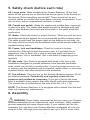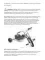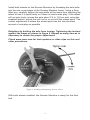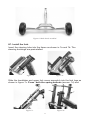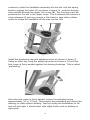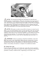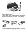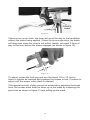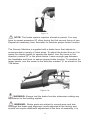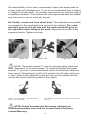
1
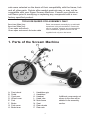
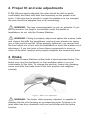
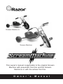
TM
TM
Scream Machine Jr.
Scream Machine
TM
This owner’s manual is applicable to the original Scream
Machine with pneumatic front tire and the Scream
Machince Jr with the airless front tire.
O w n e r ’ s
M a n u a l
Razor Owner’s Manual
+ Safety Handbook
Table of Contents
1. Parts of the Scream Machine . . . . . . . . . . . . . . . . . . . . . . . . .3
2. Proper fit and size adjustments . . . . . . . . . . . . . . . . . . . . . . . .4
3. Brake . . . . . . . . . . . . . . . . . . . . . . . . . . . . . . . . . . . . . . . . . . . .4
4. Safety . . . . . . . . . . . . . . . . . . . . . . . . . . . . . . . . . . . . . . . . . . . .5
5. Safety Check . . . . . . . . . . . . . . . . . . . . . . . . . . . . . . . . . . . . . .6
6. Assembly . . . . . . . . . . . . . . . . . . . . . . . . . . . . . . . . . . . . . . . . .6
6A. Un-box . . . . . . . . . . . . . . . . . . . . . . . . . . . . . . . . . . .7
6B. Install the rear wheels . . . . . . . . . . . . . . . . . . . . . . . .7
6C. Install fork . . . . . . . . . . . . . . . . . . . . . . . . . . . . . . . . .9
6D. Attach seat . . . . . . . . . . . . . . . . . . . . . . . . . . . . . . .11
6E. Assemble the brake cable . . . . . . . . . . . . . . . . . . . .12
6F. Brake cable adjustment . . . . . . . . . . . . . . . . . . . . . .13
6G. Pedals, cranks and front wheel drive . . . . . . . . . . .16
7. Razor Safety Tips . . . . . . . . . . . . . . . . . . . . . . . . . . . . . . . . .17
8. Limited Warranty and owner registration . . . . . . . . . . . . . . .19
NOTE: This manual contains many “Warnings” and “Cautions”
concerning the consequences of failing to maintain or inspect your
bicycle. Because any incident can result in serious injury or even death,
we do not repeat the warning of possible serious injury or death each
time such a warning is mentioned.
WARNING: Riding the Razor Scream Machine can be hazardous.
Proper inspection and maintenance of the product is your responsibility
and can reduce the risk of injury.
WARNING: The Scream Machine has been built to Razor’s
design specifications. All the original equipment supplied at the time of
2
sale were selected on the basis of their compatibility with the frame, fork
and all other parts. Certain after-market products may or may not be
compatible with your Razor Scream Machine. Consult your retailer or
call Razor prior to modifying or replacing any component with a nonfactory specified product.
TOOLS REQUIRED FOR ASSEMBLY ONLY
5mm hex (Allen) key
6mm hex (Allen) key
17mm open end wrench
10mm open end wrench for brake cable
Razor recommends assembly by an adult with
experience in bicycle mechanics. Some tools
may be supplied, however we recommend the
use of mechanic’s grade tools and use the
supplied tools only as a last resort.
1. Parts of the Scream Machine
A.
B.
C.
D.
E.
F.
G.
H.
Front wheel
Pedal
Crank arm
Wheel cover
Fork
Brake
Fork crown
Brake lever
I.
J.
K.
L.
M.
N.
O.
P.
Handlebar grip
Handlebar
Headset
Head tube
Main frame
Seat
Rear wheels
Rear axle
3
Additional components not
shown in this view will be
detailed in the assembly
section.
2. Proper fit and size adjustments
2. Fit. When properly adjusted, the rider should be able to pedal
comfortably and steer with both feet remaining on the pedals at all
times. If the rider has to stretch to reach the pedals or is too cramped,
the seat should be adjusted fore or aft accordingly.
WARNING: The age recommendation is only an estimate. If you
are too small or too large to comfortably reach the pedals or
handlebars, do not ride the Scream Machine.
WARNING: Failing to properly adjust and tighten the screws, bolts
and clamps that affix the handlebars, seat and rear wheels can cause
you to lose control and fall. When properly tightened, you cannot twist
the front wheel out of line with the handlebars or move the saddle out of
adjustment. If you can twist or force these components to move or
come off by hand, readjust and properly retighten the screws and bolts.
3. Brake
Your Razor Scream Machine is fitted with a hand-operated brake. The
brake lever may be positioned on the handlebar where it is most
comfortable for the rider. To change the position, loosen the clamping
screw and slide the brake lever to the new position and retighten
securely.
Figure 1. Brake lever adjustment.
WARNING: The brake, when properly adjusted, is capable of
skidding the tire and throwing an unsuspecting rider. Practice in an
open area free from obstacles until you are familiar with the brake
function.
4
WARNING: Cable operated brakes are very effective but must be
adjusted and maintained on a regular basis. Check or have them
checked and adjusted by a qualified mechanic. Worn brake parts,
stretched or frayed inner wires or a kinked housing indicate brake
service or parts replacement may be necessary for proper function.
4. Safety
4A. Helmets. Although not every state or municipality requires juvenileage cyclists to wear a helmet, Razor strongly recommends you wear a
properly approved helmet, such as ANSI or SNELL, even if the law
does not mandate the use of a helmet.
Suitable helmets are available in a variety of styles. The most popular
for kids is the skateboard-style “stunt” helmet. There are many brands
available and they come in various sizes to fit any child or adult.
Keep feet on the pedals at all times while riding in the seated position.
Do not ride more than one person at a time. Never use near steps or
swimming pools.
WARNING: Helmets must be properly fitted and the straps
adjusted properly to be effective. Ask your dealer to help you with the
selection, fit and adjustment of your helmet.
4B. Night riding and low-light conditions. Razor strongly
recommends against riding at night or when lighting or visibility
conditions are less than optimal (such as dawn and dusk).
WARNING: Lighting for night riding or low light conditions are not
required and are not standard equipment on the Scream Machine. We
do not recommend riding at night or in low-light conditions.
4C. Wet weather riding. Under wet conditions, the stopping power of
your brakes is reduced significantly. This makes it harder to control your
speed and easier to lose control. In wet conditions it is advised that you
ride more slowly and apply your brakes earlier and with greater caution
than in normal, dry conditions.
WARNING: Wet weather impairs traction, braking, control and
visibility. The risk of accident is increased dramatically in wet weather.
WARNING: Keep your fingers and other body parts away from the
crank, steering system, wheels and all other moving components.
5
5. Safety check (before each ride)
5A. Loose parts. While straddling the Scream Machine, lift the front
wheel off the ground two or three inches and let go so it can bounce on
the ground. Does everything sound tight? There should not be any
unusual rattles or sounds from loose parts or broken components. If you
are not sure, ask an experienced mechanic to check.
5B. Cranks and pedals. Grasp the cranks and wobble them vigorously
to check for play. The cranks and pedals should be attached and tight
with no play between the crank and drive shaft or the pedal shaft and
crank arms.
5C. Brake. Check the brake for proper function. When you pull the lever
the brake should act against the rim and provide positive braking action.
The cable should have the proper slack so the brakes do not drag, yet
the lever should not touch the handlebars when pulled except under the
hardest braking action.
5D. Frame, fork and handlebars. Check for cracks or broken
connections. Although broken frames are rare, it is possible for an
aggressive rider to bash into a curb or wall and wreck and bend or
break a frame, fork or handlebar. Get in the habit of inspecting yours
regularly.
5E. Bar ends. Your Razor is equipped with plugs in the end of the
handlebars designed to provide protection from exposed handlebar
ends, which can act like a cookie-cutter. If your bar plugs are worn out
or missing and the handlebar end is exposed, replace them or cover the
exposed end(s) with after-market bar-end protectors.
5F. Tire inflation. The front tire on the Scream Machine requires 35~45
psi inflation pressure. Periodically and regularly check the tire
pressure and reinflate as necessary. If you get a flat tire the inner
tube is available at any retailer that sells bicycle parts and accessories.
The correct size is embossed on the side of the tire (16 x 1.75).
NOTE: The Scream Machine Jr. is equipped with a airless front tire and
does not require any maintenance.
6. Assembly
WARNING: Razor highly recommends that you have your Scream
Machine assembled by an experienced, adult mechanic. Many retailers
provide assembly but some charge extra. If your retailer can’t do the
assembly, you can have your Scream Machine assembled at a bicycle
shop for a fee. Although you may have to pay up to $30 or even more
6
for assembly, it will assure the Scream Machine is properly put together
and adjusted.
ASSEMBLY NOTE: Refer to the list of tools required for assembly
on page three of this manual. If you do not have the proper tools or
understanding of the instructions in this manual, take your bike to a
qualified mechanic for assembly, service or adjustments.
6A. Un-box. Remove contents from box. Remove the cardboard and/or
plastic separators that protect the various component from damage
during shipping. Inspect the contents of the box for scratches in the
paint, dents or kinked cables that may have occurred during shipping.
Your Scream Machine was partially assembled and packed at the
factory to prevent shipping damage and there should not be any
problems, even if the box has a few scars or dents. But if there are,
contact your retailer to resolve any of these issues.
Figure 2.
6B. Install the rear wheels.
Installing the rear wheels on the Scream requires the use an 6mm allen
key and the special open-end wrench for the locking nut. The axle
consists of two parts: the axle bolt and the lock nut. These are
preinstalled on the wheels.
7
Install both wheels on the Scream Machine by threading the axle bolts
into the rear cross-beam of the Scream Machine frame. Using a 6mm
Allen key, carefully tighten the axle while at the same time checking the
wheel to see if it spins freely or if there is side-to-side play. If the wheel
will not spin freely, loosen the axle about 1/4 to 1/2 turn and, using the
supplied wrench, adjust the lock nut in or out until the wheel spins. The
correct adjustment is where the wheel spins free but has the least
amount of end-play as possible.
Retighten by holding the axle from turning. Tightening the locknut
against the frame as shown in figure 5. Repeat as many time as is
necessary to obtain the proper adjustment.
Check www.razor.com for tech updates or video clips on this and
other procedures.
Figure 5. Installing and adjusting the rear wheels.
With both wheels installed, the Scream Machine is ready for the front
fork.
8
Figure 6. Both wheels installed.
6C. Install the fork.
Insert the steering tube into the frame as shown in 7a and 7b. The
steering bushings are preinstalled.
Figure 7a.
Figure 7b.
Slide the handlebar and upper fork crown assembly into the fork legs as
shown in figure 7c. Press both the spring buttons (arrows, 7d) and
Figure 7c.
Figure 7d.
9
continue to slide the handlebar assembly into the fork until the spring
buttons engage the holes (A) as shown in figure 7e., and the steering
tube extends through the upper fork crown (B). The fork stop must be
positioned in the slot in the upper crown. The fit between the tubes is a
close tolerance fit and may require a firm hand or taps with a rubber
mallet to nudge the handlebar all the way into the fork.
Figure 7e.
Install the tensioning cap and adjusting screw as shown in figure 7f.
Using an Allen key, snug the adjusting screw as shown in 7e until the
fork crown is firmly seated against the steering bushings. This is called
“preloading.”
Figure 7f.
Once the fork crown is firmly seated, loosen the adjusting screw
approximately 1/4 to 1/2 turn. This relaxes the preloading and allows the
steering to rotate without binding. Test by turning the handlebars to full
lock left and right. It should steer with slight friction and no binding or
tight spots.
10
Figure 7g. Snug the adjusting screw.
NOTE: The steering bushings are designed for long life and
should require no maintenance. They do not require oil or any type of
“wet” lubrication. If the steering becomes rough, disassemble, inspect
and clean the bearing surfaces (soap and water is fine). Dry thoroughly
and reassemble. Although the bushings and thrust washers are selflubricating, a light application of a dry-lube can be used to facilitate the
anti-friction properties of the steering head bushings.
NOTE: Although we make every effort to keep our manual up-todate, if your Scream Machine does not look like this, then we’ve made
improvements since this document was printed. Check out the Razor
website: www.razor.com for technical updates on the latest service and
adjustment procedures. For example: later models do not have the
spacer between the fork crown and the adjusting cap as shown in 7f
and 7g.
WARNING: Failure to properly install the handlebar to the fork
legs can result in the handlebars falling off and causing risk of injury.
Periodically check to make certain the adjsuting screw is properly
tensioned and that the handlebars are securely attached to the forks.
Refer to the safety information in chapter 5 for additional details.
6D. Attach the seat.
Flip the Scream Machine on it’s side and, using the screws provided
and two allen keys, fasten the seat to the frame using one of the three
positions: forward, middle and aft, depending on the rider’s size.
11
Figure 8c.
6E. Assemble the brake cable. The brake lever is preinstalled on the
handlebars and the brake cable adjusting barrel may be either on the
cable or threaded into the lever.
Installing the cable requires placing the barrel (or ball) end of the cable
wire into the socket on the lever and “threading” the wire through the
slots in the adjusting barrel and jam nut as shown in the sequence 9a,
9b and 9c.
Figure 9a.
Figure 9b.
Figure 9c.
To properly accomplish this procedure, you may have to disconnect the
brake quick release in order to get enough slack in the wire to connect
the cable. This is shown in figures 10a and 10b.
12
Figure 10a.
Figure 10b.
WARNING: If you do not understand the procedure to connect the
brake cable, we strongly recommend you seek the help of a qualified
bicycle mechanic. If the brakes are not properly connected or adjusted
the brakes may fail and you can be seriously injured.
Tips for hooking up the V-brake
With the cable installed in the lever as shown in the various photos, pull
back the rubber booty on the cable and slide the flanged housing into
the hanger on the brake arm as shown in the sequence below.
6F. Brake cable adjustment. The main adjustment on the brake is to
take up the cable slack and bring the lever into adjustment. This is
typically accomplished with the adjusting barrel at the brake lever as
shown in figure 11.
13
Figure 11.
If there is too much slack, the lever will go all the way to the handlebar
without the brake being applied. If there is not enough slack, the brake
will drag even when the lever is not pulled. Ideally, you want 2-3mm of
play in the lever before the brake engages (as shown in figure 12).
Figure 12.
To adjust, loosen the lock ring and turn the barrel 1/4 to 1/2 turn to
loose or tighten as required and squeeze the brakes to test. Continue to
adjust until the proper cable slack is attained.
If the proper amount of play cannot be achieved by adjusting the brake
lever, the excess slack must be taken up at the brake by loosening the
pinch bolt as shown in figure 13 and pulling up the slack.
14
Figure 13.
NOTE: The brake system requires a break-in period. You may
have to repeat procedure 6F often during the first several hours of use.
Repeat as necessary from thereafter to maintain proper brake function.
The Scream Machine is supplied with a brake lever that adjusts to
accommodate a variety of hand sizes. To adjust the brake lever so it is
easier for shorter hands to operate the brake, turn the screw in the
direction marked “B” in the photo below. Leave enough gap between
the handlebar and lever to assure proper brake function. To readjust for
larger hands, turn the screw in the direction marked “A” as shown in the
13a below.
Figure 13a
WARNING: Always test the brake function whenever making any
adjustment to the braking system.
WARNING: Brake pads are subject to normal wear and tear.
Although the brake pad alignment is pre-adjusted at the factory and
should not require additional adjustment at the time of assembly, it is
15
the responsibility of the user to periodically inspect the brake pads for
excess wear and misalignment. If you do not understand how to adjust
or realign the brake pads, we strongly recommend you seek the help of
a qualified mechanic. If the brakes are not properly adjusted the brakes
may fail and you can be seriously injured.
6H. Pedals, cranks and front wheel drive. The crankarms and pedals
are supplied in the small parts box and must be installed. The crank
marked L goes on the left side and the crank marked R goes on
the right side (when sitting in the seat). Assemble as shown in the
sequence below. Tighten securely.
Figure 14a
Figure 14b
Figure 14c
NOTE: The pedal marked “L” and the corresponding crank arm
have “backward” or reverse threads. To install and tighten the pedal
marked “L” you turn it counterclockwise, which is the reverse direction
from normal. Attempting to install an R pedal in the left side crank arm
or the L pedal in the right-side crank arm will ruin the pedals and the
cranks and could seize the pedals in the cranks.
Figure 15a. Tightening a left-hand pedal
with a reverse thread.
15b. Tightening a right-side pedal with a normal
thread
NOTE: Pedals threaded into the wrong crankarm are
considered operator error and not covered under the Razor
Limited Warranty.
16
7. Razor Safety Tips
WARNING TO PARENTS: Kids need to be taught and be
frequently reinforced of the importance of safe riding, the rules of the
road and the dangers and hazards of traffic, especially motor vehicle
traffic. Parents and children are urged to read and understand these
safety tips together.
7A. Rules of the road
Do not play in the road or street.
Do not ride on streets.
Do not ride at night.
Stop for all stop signs
Use crosswalks to cross streets
Always walk at crosswalks.
Never use near steps or swimming pools
7B. Your driveway. Driveway accidents are frequent and often fatal.
Realize the danger of your own and all other driveways. There may be
obscured vision caused by trees, bushes or cars. Your driveway is not a
launching pad for fast roll-outs! Observe the following driveway safety
tips:
Look left, right and left again before exiting onto sidewalks or into
playground areas.
7C. Stop signs. Running a stop sign is a sure way to get hit by a car
and killed. Remember, always stop at every stop sign or stop light.
Always stop and walk across only when it is clear. Do not assume that
drivers of motor vehicles can see you. In fact, assume that every driver
cannot see you and that they are not paying attention. Observe the
following safety tips:
Stop at all stop signs and lights, regardless of traffic conditions.
Look in every direction of traffic before proceeding to walk across
Watch especially for oncoming traffic making left turns.
Watch for cars behind you or next to you making right turns.
Wait for traffic to clear before proceeding.
7D. Turning without warning. Children are often struck from behind
because they made unexpected turns into traffic, or they inadvertently
veered into traffic when looking over their shoulder. Observe the
following safety tips for left turns:
Do not cut across the street, cross only at intersections.
Practice looking over your shoulder to the rear without accidentally
17
turning (do this only in an open space free from traffic and
obstructions).
7E. Riding at night and in low visibility. Do not ride at night or in low
visibility. See section 4 for more information.
7F. Rules of the Road.
Wear a helmet. Wear shoes.
Become aware of and learn your local bicycle laws and regulations.
Most states and communities have rules regarding helmet use,
bicycle licensing, riding on sidewalks, grinding and so on. It is the
responsibility of parents to make sure their children know and obey
all rules and regulations.
The Scream Machine is intended for sidewalk and playground use.
You must share this space with others including, pedestrians,
skaters and other players. Respect their rights!
Ride defensive. Assume that pedestrians, skaters and other players
are so absorbed in their own world that they are not paying any
attention to you and that they will run you down or step out in front
of you, all without any warning.
Watch for obstacles such as pot holes, sewer grates, expansion
cracks, and road or construction debris (such as nails or other
foreign objects) that could catch your wheel or force you to swerve
into traffic or lose control.
Stop at all stop signs and lights.
Never ride with headphones or use a cell phone when riding.
Never carry a passenger.
Never hitch a ride with another vehicle.
Do not weave into traffic or make sudden turns.
Observe and yield the right-of-way as prescribed by local traffic
rules.
Riding the Scream Machine may be a hazardous activity and has
inherent dangers that no amount of care, caution, instruction or
expertise can eliminate. Certain conditions may cause the equipment to
fail without fault of the manufacturer. Activities involving the use of
bicycles carry the risk of injury or death.
8.
18
Razor Limited Warranty and Registration
The manufacturer warranties this product to be free of manufacturing
defects for a period of six months from date of purchase. This Limited
Warranty does not cover normal wear and tear, tires, tubes or cable, nor
any damage, failure or loss caused by improper assembly,
maintenance, storage or use of the Scream Machine.
This Limited Warranty will be void if the product is ever:
•
used in a manner other than for recreation or transportation;
•
modified in any way;
•
rented.
Check local laws and regulations to see where you can ride your
Scream Machine legally.
The manufacturer is not liable for incidental or consequential loss nor
damage due directly or indirectly from the use of this product.
To obtain service under this warranty you must, within the
warranty period, contact Razor USA LLC directly by e-mail at
[email protected]. Razor will provide warranty replacement
at its sole discretion.
Authorized warranty service is ONLY available from Razor USA
LLC.
19
QUESTIONS?
Please read the owner’s manual thoroughly. If you still have
questions, check the website for updates and contact information.
Spare rear wheels are available! Keep your Scream Machine
running for years with these and other genuine Razor spare parts.
Visit our website and e-mail us for more information
on spare part availability.
Specifications subject to change without notice.
Patent Pending
SM Rev. 4b.11/22/02 ©Copyright 2002, Razor USA.
Cerritos, CA
All rights reserved.
Photos by Arthur Cambridge
razor usa llc cerritos, ca 90703 www.razor.com