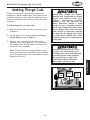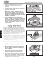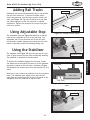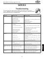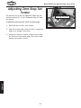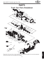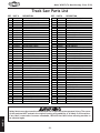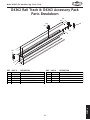
1
MODEL W1835 Track saw OWNER'S MANUAL (FOR MODELS MANUFACTURED SINCE 12/12) Phone: (360) 734-3482 • Online Technical Support: [email protected] COPYRIGHT © DECEMBER, 2012 BY WOODSTOCK INTERNATIONAL, INC. 4000311 WARNING: NO PORTION OF THIS MANUAL MAY BE REPRODUCED IN ANY SHAPE OR FORM WITHOUT THE WRITTEN APPROVAL OF WOODSTOCK INTERNATIONAL, INC. #15384ST Printed in China This manual provides critical safety instructions on the proper setup, operation, maintenance, and service of this machine/tool. Save this document, refer to it often, and use it to instruct other operators. Failure to read, understand and follow the instructions in this manual may result in fire or serious personal injury—including amputation, electrocution, or death. The owner of this machine/tool is solely responsible for its safe use. This responsibility includes but is not limited to proper installation in a safe environment, personnel training and usage authorization, proper inspection and maintenance, manual availability and comprehension, application of safety devices, cutting/sanding/grinding tool integrity, and the usage of personal protective equipment. The manufacturer will not be held liable for injury or property damage from negligence, improper training, machine modifications or misuse. Some dust created by power sanding, sawing, grinding, drilling, and other construction activities contains chemicals known to the State of California to cause cancer, birth defects or other reproductive harm. Some examples of these chemicals are: • Lead from lead-based paints. • Crystalline silica from bricks, cement and other masonry products. • Arsenic and chromium from chemically-treated lumber. Your risk from these exposures varies, depending on how often you do this type of work. To reduce your exposure to these chemicals: Work in a well ventilated area, and work with approved safety equipment, such as those dust masks that are specially designed to filter out microscopic particles. ELECTRICAL........................................ 12 Circuit Requirements........................... 12 Polarized Plug.................................... 13 Extension Cords................................. 13 PARTS................................................ 27 Track Saw Parts Breakdown................... 27 Track Saw Parts List............................ 28 Rail Track Parts Breakdown.................... 29 Rail Track Parts List............................. 29 WARRANTY......................................... 33 OPERATIONS MAINTENANCE OPERATIONS........................................ 16 General........................................... 16 Using Saw......................................... 16 Blade Selection.................................. 16 Changing Blades................................. 17 Riving Knife Adjustment....................... 18 Setting Cutting Depth.......................... 19 Setting Cutting Angle........................... 19 Making Straight Cuts............................ 20 Making Plunge Cuts............................. 21 Using Rail Track................................. 22 Adding Rail Tracks............................... 23 Using Adjustable Stop.......................... 23 Using the Stabilizer............................. 23 SET UP SETUP............................................... 14 Unpacking........................................ 14 Inventory......................................... 14 Optional Accessories............................ 14 Dust Collection.................................. 15 SERVICE............................................. 25 Troubleshooting.................................. 25 Adjusting Zero-Stop Set Screw................ 26 ELECTRICAL SAFETY................................................8 Safety Instructions for Power Tools............ 8 Additional Safety for Track Saws............. 10 Understanding Kickback........................ 11 Preventing Kickback............................ 11 MAINTENANCE..................................... 24 Electrical......................................... 24 Cleaning.......................................... 24 Lubrication....................................... 24 Blade.............................................. 24 SAFETY INTRODUCTION......................................2 Woodstock Technical Support................... 2 Glossary of Terms................................. 3 Controls and Features............................ 6 INTRODUCTION Contents SERVICE PARTS USE THE QUICK GUIDE PAGE LABELS TO SEARCH OUT INFORMATION FAST! INTRODUCTION Woodstock International, Inc. is committed to customer satisfaction. Our intent with this manual is to include the basic information for safety, setup, operation, maintenance, and service of this product. In the event that questions arise about your machine, please contact Woodstock International Technical Support at (360) 734-3482 or send e-mail to: [email protected]. Our knowledgeable staff will help you troubleshoot problems or process warranty claims. If you need the latest edition of this manual, you can download it from http://www.shopfox.biz. If you have comments about this manual, please contact us at: Woodstock International, Inc. Attn: Technical Documentation Manager P.O. Box 2309 Bellingham, WA 98227 Email: [email protected] PARTS SERVICE MAINTENANCE OPERATIONS SET UP ELECTRICAL SAFETY Woodstock Technical Support USE THE QUICK GUIDE PAGE LABELS TO SEARCH OUT INFORMATION FAST! Glossary of Terms The following is a list of common definitions, terms and phrases used throughout this manual as they relate to this track saw and woodworking in general. Become familiar with these terms for assembling, adjusting or operating this machine. Perpendicular: Lines or planes that intersect and form right angles. i.e. the blade is perpendicular to the table surface. Arbor: Metal shaft extending from the drive mechanism, to which saw blade is mounted. The blade is held in place on the arbor using a special arbor bolt and arbor washer. Riving Knife: Metal plate located behind the blade. It maintains the kerf opening in the wood when performing a cutting operation. Bevel Edge Cut: Tilting the saw blade to an angle between 0° and 45° to cut a beveled edge onto a workpiece. Straightedge: A tool used to check the flatness, parallelism, or consistency of a surface(s). Blade Guard: Metal or plastic safety device that encases the saw blade. Its function is to prevent the operator from coming into contact with the saw blade. Through Cut: A sawing operation in which the workpiece is completely sawn through. Kerf: The resulting cut or gap in the workpiece after the saw blade passes through during a cutting operation. Rip Cut: Cutting operation in which the rip fence is used to cut with the grain, or across the widest width of the workpiece. Kickback: An event in which the tool is propelled back towards the operator at a high rate of speed. Plunge Cut: A sawing operation in which the cut is started above the workpiece; the blade engages the workpiece by "plunging" down at the beginning of the cut, and advances once the blade cuts through the workpiece. Parallel: Being an equal distance apart at every point along two given lines or planes. i.e. the rip fence face is parallel to the face of the saw blade. -3- INTRODUCTION Model W1835 (For Machines Mfg. Since 12/12) INTRODUCTION Model W1835 (For Machines Mfg. Since 12/12) MACHINE SPECIFICATIONS © Woodstock International, Inc. • Phone #: (800) 840-8420 • Web: www.shopfox.biz model W1835 Track SaW Product Dimensions: Weight .....................................................................................................................11 lbs. Width (side-to-side)/Depth (front-to-back)/Height .............................................. 13 3⁄8" x 10 1⁄4" x 9 1⁄2" Shipping Dimensions: Type .............................................................................................................. Cardboard Box Content ................................................................................................................Track Saw Weight .....................................................................................................................16 lbs. Width/Depth/Height ..................................................................................... 13" x 10 5⁄8" x 9 1⁄4" Electrical: Switch .............................................................................................. Trigger with Safety Latch Cord Length................................................................................................................. 8 ft. Cord Gauge ..............................................................................................................18 AWG Plug Type Included ........................................................................NEMA 1-15 Two-Prong Polarized Motor: Type .................................................................................................................... Universal Horsepower .............................................................................................................. 1.1 KW Voltage ...................................................................................................................... 120V Phase................................................................................................................Single-Phase Amps ............................................................................................................................ 9A Speed .................................................................................................................. 5500 RPM Cycle ........................................................................................................................ 60 Hz Main Specifications: Blade Specifications Blade Diameter .......................................................................................... 160mm (6 1⁄4") Blade Tilt ......................................................................................................... 0° – 45° Arbor Size .......................................................................................................... 20mm Arbor Speed .................................................................................................... 5500 RPM Blade Rim Speed .............................................................................................. 9070 FPM Cutting Capacities Maximum Depth Maximum Depth Maximum Depth Maximum Depth of of of of Cut Cut Cut Cut at at at at 90° 45° 90° 45° (without rail track) ........................................................... 2 5⁄32" (without rail track) ............................................................ 1 5⁄8" (with rail track) ...............................................................1 31⁄32" (with rail track) ............................................................... 1 7⁄16" Construction Saw Construction .................................................................Aluminum and Engineered Plastic Hand Grips .................................................................................... Heavy-Duty Rubberized Rail Track .......................................................................................................Aluminum Number of Dust Ports ................................................................................................... 1 Dust Port Size ........................................................................................................ 1 1⁄2" Model W1835 Machine Specifications, Page 1 of 2 -4- Other Specifications: Country of Origin ......................................................................................................... China Warranty .................................................................................................................. 2 Year Serial Number Location .........................................................................ID Label on Motor Housing Assembly Time ......................................................................................................10 Minutes Features: Anti-Kickback Design with Spring-Loaded Riving Knife Low-Profile Blade Guard for Cuts as Close as 5⁄8" from Wall 1 1⁄2" Dust Port for Efficient Dust Collection Versatile—Saw Can be Used With or Without Track Precision Depth Control Scale in 1⁄32" Increments Optional Accessories: D4362 55" Rail Track D4363 Accessories Pack (Includes rail connector, (2) F-clamps, stop, and stabilizer) D4364 48-Tooth Replacement Blade Model W1835 Machine Specifications, Page 2 of 2 -5- INTRODUCTION Model W1835 (For Machines Mfg. Since 12/12) INTRODUCTION Model W1835 (For Machines Mfg. Since 12/12) Controls and Features A B H G C D D E F E A. Primary Handle: Used to steady the saw when plunging and to advance its position on the workpiece/rail track. E. Rail Adjustment Knobs: Allows for adjustment of play in how the saw slides along the guide rail track to ensure accurate cuts. B. Secondary Handle: Used to lower saw blade into the workpiece once the plunge release and ON/OFF trigger have been pulled. F. Zero-Stop Set Screw: Fine-tunes the zerostop point for calibrating the bevel gauge. G. ON/OFF Trigger: Starts/stops the saw blade rotation and motor. C. Depth Stop Lock Knob: Sets the maximum depth at which the saw blade will enter the workpiece. H. Plunge Release: Allows the saw blade to pivot down and plunge into the workpiece. D. Bevel Gauge & Lock Knob (Front and Rear): Sets the angle (up to 45°) at which the saw blade will cut into the workpiece and locks it into place. -6- INTRODUCTION Model W1835 (For Machines Mfg. Since 12/12) I J O N M K L I. Dust Collection Port: 1 1⁄2" port for connection to a dust collection system or shop vacuum (not included). M. Base Plate: Can be attached to the accompanying rail track or placed directly on the workpiece if track is not used. J. Arbor Bolt: Holds saw blade in place on the 20mm arbor. Remove it to change blades. N. Blade Lock: Prevents the blade from rotating when changing blades. K. Spring-Loaded Riving Knife: Lowers into the kerf behind the blade to reduce the risk of binding or pinching that causes kickback. Spring-loaded operation allows the riving knife to work with plunge cuts. Also provides limited protection against accidental blade contact if kickback occurs. O. Cutting Indicator Arrows: Three embossed indicator arrows, indicating maximum blade reach for the front and rear, as well as the center point of the blade. L. Saw Blade: This saw is designed for a blade that has a 160mm diameter, a 20mm arbor, and is 2.2mm thick. A 48-tooth, carbidetipped blade is included. -7- Model W1835 (For Machines Mfg. Since 12/12) SAFETY SAFETY For Your Own Safety, Read Instruction Manual Before Operating this Power Tool The purpose of safety symbols is to attract your attention to possible hazardous conditions. This manual uses a series of symbols and signal words intended to convey the level of importance of the safety messages. The progression of symbols is described below. Remember that safety messages by themselves do not eliminate danger and are not a substitute for proper accident prevention measures. Always use common sense and good judgment. Indicates an imminently hazardous situation which, if not avoided, WILL result in death or serious injury. Indicates a potentially hazardous situation which, if not avoided, COULD result in death or serious injury. Indicates a potentially hazardous situation which, if not avoided, MAY result in minor or moderate injury. It may also be used to alert against unsafe practices. NOTICE This symbol is used to alert the user to useful information about proper operation of the tool. Safety Instructions for Power Tools DISCONNECT POWER FIRST. Always disconnect tool from power supply BEFORE making adjustments, changing tooling, or servicing machine. This prevents an injury risk from unintended startup or contact with live electrical components. OWNER’S MANUAL. Read and understand this owner’s manual BEFORE using machine. TRAINED OPERATORS ONLY. Untrained operators have a higher risk of being hurt or killed. Only allow trained/supervised people to use this power tool. When tool is not being used, disconnect power, and store in out-ofreach location to prevent unauthorized use— especially around children. Make workshop kid proof! EYE PROTECTION. Always wear ANSI-approved safety glasses or a face shield when operating or observing machinery to reduce the risk of eye injury or blindness from flying particles. Everyday eyeglasses are not approved safety glasses. DANGEROUS ENVIRONMENTS. Do not use tools in areas that are wet, cluttered, or have poor lighting. Operating tools in these areas greatly increases risk of accidents and injury. ELECTRICAL SAFETY. Tool plug must match outlet. Double-insulated tools have a polarized plug (one blade is wider than the other), which must be plugged into a polarized outlet. Never modify plug. Do not use adapter for grounded tools. Use a ground fault circuit interrupter if operation is unavoidable in damp locations. Avoid touching grounded surfaces when operating tool. MENTAL ALERTNESS REQUIRED. Full mental alertness is required for safe operation of power tools. Never operate under the influence of drugs or alcohol, when tired, or when distracted. -8- Model W1835 (For Machines Mfg. Since 12/12) CHILDREN & BYSTANDERS. Keep children and bystanders at a safe distance from the work area. Stop using machine if they become a distraction. FORCING TOOLS. Use the right tool for the job, and do not force it. It will do the job safer and better at the rate for which it was designed. HAZARDOUS DUST. Dust created while using tools may cause cancer, birth defects, or long-term respiratory damage. Be aware of dust hazards associated with each workpiece material, always wear a NIOSH-approved respirator, and connect tool to an appropriate dust collection device to reduce your risk. USE RECOMMENDED ACCESSORIES. Consult this owner’s manual or the manufacturer for recommended accessories. Using improper accessories will increase the risk of serious injury. HEARING PROTECTION. Always wear hearing protection when operating or observing loud machinery. Extended exposure to this noise without hearing protection can cause permanent hearing loss. MAINTAIN WITH CARE. Keep cutting tool edges sharp and clean. Follow all maintenance instructions and lubrication schedules to keep tool in good working condition. A tool that is improperly maintained could malfunction, leading to serious personal injury or death. Only have tool serviced by qualified servicepersonnel using matching replacement parts. REMOVE ADJUSTING TOOLS. Never leave adjustment tools, chuck keys, wrenches, etc. in or on tool—especially near moving parts. Verify removal before starting! CHECK DAMAGED PARTS. Regularly inspect tool for any condition that may affect safe operation. Immediately repair or replace damaged or mis-adjusted parts before operating tool. INTENDED USAGE. Only use tool for its intended purpose. Never modify or alter tool for a purpose not intended by the manufacturer or serious injury or death may result! SAFE HANDLING. Firmly grip tool. To avoid accidental firing, do not keep finger on switch or trigger while carrying. MAINTAIN POWER CORDS. When disconnecting cord-connected tools from power, grab and pull the plug—NOT the cord. Carrying or pulling the cord may damage wires inside. Do not handle cord/plug with wet hands. Avoid cord damage by keeping it away from heated surfaces, high traffic areas, harsh chemicals, sharp edges, moving parts, and wet/damp locations. Damaged cords increase risk of electrocution. SECURING WORKPIECE. When required, use clamps or vises to secure workpiece. A secured workpiece protects hands and frees both of them to operate the tool. UNATTENDED OPERATION. Never leave tool running while unattended. Turn tool off and ensure all moving parts completely stop before walking away. GUARDS & COVERS. Guards and covers reduce accidental contact with moving parts or flying debris. Make sure they are properly installed, undamaged, and working correctly. EXPERIENCING DIFFICULTIES. If at any time you experience difficulties performing the intended operation, stop using the machine! Contact our Technical Support at (360) 734-3482. AWKWARD POSITIONS. Keep proper footing and balance at all times when operating tool. Do not overreach! Avoid awkward hand positions that make tool control difficult or increase the risk of accidental injury. -9- SAFETY WEARING PROPER APPAREL. Do not wear clothing, apparel or jewelry that can become entangled in moving parts. Always tie back or cover long hair. Wear non-slip footwear to avoid accidental slips, which could cause loss of workpiece control. Wear hard hat as needed. Model W1835 (For Machines Mfg. Since 12/12) SAFETY Additional Safety for Track Saws STOPPING AND RESTARTING CUTS. Allow blade to reach full speed before cutting. Complete all cuts when possible. If a cut must be interrupted, let blade come to a complete stop before removing saw. Before resuming, place blade in center of kerf and verify teeth do not contact workpiece. BLADE MAINTENANCE. Always ensure that the saw blades are sharp, undamaged, and tightly attached before each use. Only use blades that meet the specifications listed on the data sheet. RECOMMENDED ACCESSORIES. Only use appropriate blades for this saw. Do not use blades with different diameters or arbor hole shapes/sizes, as they will not rotate concentrically and may damage the saw and throw blade fragments with deadly force. CUTTING CORRECT MATERIAL. Use the correct blade for the type of material being cut. Do not use this saw for cutting logs, roots, or trimming shrubs and trees. Do not cut warped, twisted, or cupped workpieces. RIVING KNIFE. Make sure the riving knife is thicker than the saw blade but thinner than the blade teeth. The riving knife must be present in the kerf and properly adjusted with the blade to be effective. PLUNGE CUTS. To decrease risk of kickback, do not allow the saw base to shift while performing beveled plunge cuts. Before making blind plunge cuts, verify the cutting path is clear of obstructions (electrical wires, gas lines, plumbing, metal or stone, etc.) to reduce the risk of explosion, fire, electrocution, property damage, or kickback. Disconnect fuses or circuit breakers, and shut off nearby water and gas lines if cutting nearby. GUARDS. Ensure guards are in place and operating correctly before each cut. Repair or replace guard if it is damaged. PHYSICAL SAFETY. Keep hand and fingers clear of cutting path at all times. Never reach under workpiece near blade, and do not perform a cut while supporting workpiece with one hand or balancing it on a leg or any other body part. WORKPIECE SUPPORT. Properly support all workpieces and cutoffs to reduce risk of binding and kickback. Place supports under both sides of the cut line. CUTTING DEPTH. Set the cutting depth so the blade protrudes no more than 1⁄8" beyond the backside or bottom of the workpiece. WORKPIECE CLEARANCE. Ensure adequate clearance under workpiece to reduce risk of blade contacting materials (concrete, rocks, metal, etc.) that could damage it and cause it to fly apart. STRAIGHT CUTS. Only make straight cuts. Always use a guide to reduce risk of binding and kickback. Do not make freehand cuts! READ and understand this entire manual before using this machine. Serious personal injury may occur if safety and operational information is not understood and followed. DO NOT risk your safety by not reading! Use this and other machinery with caution and respect. Always consider safety first, as it applies to your individual working conditions. No list of safety guidelines can be complete—every shop environment is different. Failure to follow guidelines could result in serious personal injury, damage to equipment or poor work results. -10- Model W1835 (For Machines Mfg. Since 12/12) Understanding Kickback Follow cuts through to completion whenever possible. If a cut must be stopped before completion or the blade begins to bind, release the ON/OFF trigger and hold the saw motionless while the blade comes to a complete stop before removing it from the workpiece. When resuming the cut, center your blade in the kerf and ensure that the teeth are not touching the workpiece. • Only use sharp, clean, undamaged blades. Dull blades create much more friction and resistance while cutting, which greatly increases the risk of kickback. Kickback is a sudden and unexpected expulsion of the saw from the workpiece, which can violently propel the saw back toward the operator, resulting in accidental blade contact or impact injury. Kickback is caused when the saw blade becomes misaligned, pinched, bound, or comes in contact with a material it is unable to cut. When kickback occurs, the saw blade becomes immediately immobile. The force produced by the motor is diverted from the blade and transferred to the saw, pushing it up and away from the workpiece and potentially toward the operator. The lack of warning and high risk of injury from kickback makes it extremely important to: (1) reduce the risk of kickback, and (2) protect yourself in case it does occur. Preventing Kickback Take these precautions to help prevent the most common causes of kickback: • Hold the saw firmly with both hands and position arms to help resist kickback forces. Always stand to one side of the saw when operating—never directly behind it. When kickback does occur, it will eject the saw back toward the operator. • Ensure the workpiece remains level and immobile throughout your cut. Do not cut warped, cupped, or twisted workpieces. Minimize the chances of the workpiece rocking, rotating, or shifting, which could bind the blade and allow kickback to occur. Clamp workpiece in place if necessary. • Support large panels, making sure supports are positioned under both sides of the cutting line. • Allow blade to reach full speed before starting the cut. • To help prevent the blade from binding in the workpiece: (1) keep cuts straight, (2) maintain a consistent depth and angle throughout cut, (3) provide proper workpiece support on both sides of the cut (see Figures 1–2). -11- Workpiece Support Figure 1. Cutting with proper workpiece support. Figure 2. Cutting with improper support. SAFETY • Model W1835 (For Machines Mfg. Since 12/12) ELECTRICAL ELECTRICAL Circuit Requirements This tool must be connected to the correct size and type of power supply circuit, or fire or electrical damage may occur. Read through this section to determine if an adequate power supply circuit is available. If a correct circuit is not available, a qualified electrician MUST install one before you can connect the machine to power. A power supply circuit includes all electrical equipment between the breaker box or fuse panel in the building and the machine. The power supply circuit used for this machine must be sized to safely handle the full-load current drawn from the machine for an extended period of time. (If this tool is connected to a circuit protected by fuses, use a time delay fuse marked D.) The tool must be properly set up before it is safe to operate. DO NOT connect this tool to the power source until instructed to do so later in this manual. Full-Load Current Rating The full-load current rating is the amperage a tool draws at 100% of the rated output power. On machines with multiple motors, this is the amperage drawn by the largest motor or sum of all motors and electrical devices that might operate at one time during normal operations. Full-Load Current Rating at 120V.....................9 Amps Circuit Requirements for 120V This machine is prewired to operate on a 120V power supply circuit that has a verified ground and meets the following requirements: Circuit Type....................... 120V, 60 Hz, Single-Phase Circuit Size.............................................. 15 Amps Plug/Receptacle..................................... NEMA 1-15 -12- Incorrectly wiring or grounding this tool can cause electrocution, fire, or machine damage. To reduce this risk, only an electrician or qualified service personnel should do any required electrical work on this tool. NOTICE The circuit requirements listed in this manual apply to a dedicated circuit— where only one tool will be running at a time. If this tool will be connected to a shared circuit where multiple devices will be running at the same time, consult with an electrician to ensure that the circuit is properly sized for safe operation. Model W1835 (For Machines Mfg. Since 12/12) Polarized Plug This tool is double-insulated and therefore does not have a grounding wire or plug. The two-pronged, NEMA 1-15 plug has a polarized end; this means that one prong (the neutral connector) is wider than the other (the hot connector). Polarized plugs must be used only with polarized receptacles. Do not attempt to plug this tool into a non-polarized receptacle. If a polarized receptacle is not available, a qualified electrical technician will have to install one before the saw can be plugged in. 5-15 Receptacle 1-15 Plug Hot Neutral This tool is equipped with a power cord that has an equipment-grounding wire and NEMA 1-15 grounding plug. The plug must only be inserted into a matching receptacle (see Figure) that is properly installed and grounded in accordance with local codes and ordinances. Extension Cords When using extension cords, make sure the cords are rated for outdoor use. Outdoor use cords are marked with a "W-A" or a "W" to signify their rating. Always check to make sure that the extension cords are in good working order and free of any type of damage, such as exposed wires, cuts, creased bends, or missing prongs. Extension cords cause voltage drop, which may damage electrical components and shorten motor life. Voltage drop increases as the extension cord size gets longer and the gauge size gets smaller (higher gauge numbers indicate smaller sizes. When using extension cords, always choose the shortest cord possible, with the greatest-sized gauge. Below is a list of minimum gauge sizes needed for running a 7-10 Amp tool at different lengths: 25 Feet................................................... 16 AWG 50 Feet................................................... 16 AWG 100 Feet................................................. 14 AWG -13- ELECTRICAL Figure 3. NEMA 1-15 plug & receptacle. For 120V Connection Model W1835 (For Machines Mfg. Since 12/12) SETUP Unpacking This tool has been carefully packaged for safe transportation. If you notice the machine has been damaged during shipping, please contact your authorized Shop Fox dealer immediately. Inventory SETUP The following is a description of the main components shipped with the Model W1835. Lay the components out to inventory them. Keep tool disconnected from power until instructed otherwise. Note: If you can't find an item on this list, check the mounting location on the tool or examine the packaging materials carefully. Occasionally we pre-install certain components for safer shipping. A Qty Box Inventory (Figures 4-5) A.Saw...........................................................1 B. Blade 48T....................................................1 C. Hex Wrench 5mm (not shown)...........................1 B Figure 4. Track saw and blade. Optional Accessories The following accessories are available to help you get the most out of your W1835 Track Saw. D4362—55" Guide Rail Figure 5. Track saw on D4362 55" guide rail. -14- Model W1835 (For Machines Mfg. Since 12/12) D4363—Accessory Pack for W1835 A. Rail Track Connector.......................................1 B.Stabilizer.....................................................1 C. Adjustable Stop.............................................1 D.F-Clamps.....................................................2 A B C D Figure 6. D4363 Accessories Pack. D4364—48-Tooth Blade for W1835 Saw SETUP Figure 7. D4364 48-Tooth Blade. Dust Collection Recommended CFM at Dust Port:................. 100 CFM Do not confuse this CFM recommendation with the rating of the dust collector. To determine the CFM at the dust port, you must take into account many variables, including the CFM rating of the dust collector, the length of hose between the dust collector and the tool, the amount of branches or Y's, and the amount of other open lines throughout the system. Explaining this calculation is beyond the scope of this manual. If you are unsure of your system, consult an expert or purchase a good dust collection "how-to" book. This tool creates substantial amounts of dust during operation. Breathing airborne dust on a regular basis can result in permanent respiratory illness. Reduce your risk by wearing a respirator and capturing the dust with a dust collection system. To connect a dust collection hose do these steps: 1. Fit the 1 1⁄2" dust hose over the dust port (see Figure 8), and secure in place with a hose clamp. 2. Tug the hose to make sure it does not come off. Note: A tight fit is necessary for proper performance. Dust Port Figure 8. Dust port location. -15- Model W1835 (For Machines Mfg. Since 12/12) OPERATIONS General This tool will perform many types of operations that are beyond the scope of this manual. Many of these operations can be dangerous or deadly if performed incorrectly. The instructions in this section are written with the understanding that the operator has the necessary knowledge and skills to operate this tool. If at any time you are experiencing difficulties performing any operation, stop using the tool! If you are an inexperienced operator, we strongly recommend that you read books or trade articles, or seek training from an experienced track saw operator before performing any unfamiliar operations. Above all, your safety should come first! OPERATIONS Using Saw The W1835 Track Saw is designed to be used with wood and wood-based material. This tool should not be used to cut ferrous metals (steel, cast iron, etc.), glass, aluminum, plastics, ceramics, tile, drywall, cementious backer board, carpet, foam, or any type of food. Blade Selection Always use sharp blades and select the correct blade for the material being cut. The resulting cut will be cleaner and there will be less stress on the machine. Always inspect saw blades closely before installation, and never use saw blades with bent or missing teeth, or that appear damaged in any way. The W1835 comes with a 48-tooth carbide-tipped blade that will effectively handle most wood and wood-like materials. Blade Requirements: • • 160mm diameter 20mm round arbor bore Keep in mind that blade teeth should never be thinner than the riving knife; otherwise the riving knife could get stuck in the kerf. -16- READ and understand this entire instruction manual before using this tool. Serious personal injury may occur if safety and operational information is not understood and followed. DO NOT risk your safety by not reading! Model W1835 (For Machines Mfg. Since 12/12) Changing Blades When changing saw blades, always keep the saw in an upright position. Position the saw along the edge of a workbench or table, so that the blade can be lowered safely down below the surface edge of the workspace while the saw remains upright. To change the blade, do these steps: 1. DISCONNECT SAW FROM POWER! 2. Engage the plunge release and lower the blade down far enough to expose the arbor bolt. Push the blade lock (see Figure 9) and rotate the arbor bolt with a 5mm hex wrench until the blade locks in place. Severe lacerations, amputation, or death can occur if blade changing/ adjustment is attempted while saw is connected to power. Always unplug saw before changing or making any adjustments to blade or riving knife, or performing any maintenance to the saw that would require direct physical contact with the blade. Plunge Release Blade Lock 3. With your free hand, turn the arbor bolt counterclockwise with a 5mm hex wrench to loosen it, as shown in Figure 10. 4. Once the arbor bolt has been loosened, use your fingers to carefully remove it, along with the arbor washer, then guide the blade down and out of the saw. Figure 9. W1835 top view. 6. Make sure grooves of the arbor washer are correctly lined up with the flange and thread the arbor bolt and washer into place with your free hand. The correct order of installation is shown in Figure 11 for your reference. OPERATIONS 5. When ready to insert a new blade, lower the saw back down so that the arbor flange is visible. Insert a new blade into the saw. Align the center of the blade over the arbor flange and let it rest there. Figure 10. Loosening arbor bolt. 7. Engage the blade lock to keep the arbor flange steady, and tighten the arbor bolt firmly using a 5mm hex wrench. Arbor Flange Blade Arbor Bolt Washer Figure 11. Saw blade and blade-fastening components. -17- Model W1835 (For Machines Mfg. Since 12/12) Riving Knife Adjustment The riving knife must be properly aligned with the blade and positioned the correct distance away from it to work effectively. As with changing the blade, always keep the saw upright, and position the saw along the edge of a workbench or table so that the blade and riving knife can be lowered safely down below the surface edge. To adjust the riving knife, do these steps: Riving Knife Port Hole Figure 12. Location of riving knife port hole. 1. Engage the plunge release and lower the blade down until the riving knife lock is accessible through the port hole (see Figure 12). 2. Using a 5mm hex wrench, loosen the riving knife lock, as shown in Figure 13. 3. Position the riving knife 3⁄32"– 1⁄8" (2-3mm) away from the saw blade teeth, and ensure that it is just above the lowest part of the blade. OPERATIONS 4. Retighten the riving knife lock after making the adjustment. 5. Check to make sure that the riving knife is properly aligned with the blade. Place a straightedge against the side of the blade and riving knife; the straightedge should lie flush against both objects, indicating that they are aligned. —If the two are misaligned, then check that your blade thickness is not less than the thickness of the riving knife. —If the thickness is correct, then remove the riving knife and check for straightness. NEVER use a warped or damaged riving knife when making a cut; doing so could cause kickback. -18- Figure 13. Loosening the riving knife lock. Model W1835 (For Machines Mfg. Since 12/12) Setting Cutting Depth Cutting depth should always be set at just past the bottom of the workpiece. The best way to accurately set the depth is to position the saw along one edge of the workpiece so that the blade extends below the workpiece (similar to the process of allowing the blade to extend when being changed). Once the blade is extended, determine the necessary depth by allowing the blade to extend roughly 1⁄8" beyond the bottom of the workpiece, as shown in Figure 14. ⁄8" Blade Clearance 1 Figure 14. Setting saw depth by aligning blade with the workpiece. To set the cutting depth, do these steps: 1. Loosen the depth stop lock knob and adjust the depth gauge along the scale to the maximum depth desired for the cut (see Figure 15). Depth Scale Depth Gauge 2. Retighten the lock knob. The saw blade will now extend only to that set point. Note: The cutting depth shown on the scale is the depth WITHOUT the rail track. The track adds an additional 3⁄16" thickness to the cutting point. The cutting angle of the blade can be set with the bevel gauge. Cutting angles can be set from 90°–45°. To set the cutting angle, do these steps: Figure 15. Depth-setting components. Front Bevel Lock Knob 1. Loosen the front and rear bevel gauge knobs (see Figure 16). 2. While holding the base plate, carefully pull the body of the saw out to the desired angle. (Refer to the angular scale along the side of the bevel gauge.) 3. Tighten the front and rear bevel gauge knobs. -19- Bevel Gauge Zero-Stop Set Screw Figure 16. Angle-setting components. OPERATIONS Setting Cutting Angle Depth Stop Lock Knob Model W1835 (For Machines Mfg. Since 12/12) Making Straight Cuts There are generally two types of cuts made with this saw—straight cuts and plunge cuts. Straight cuts are made with the blade already extended, with the cut beginning on one edge of the workpiece and ending on the opposite side. These cuts work well for cutting objects into separate pieces and for straight-lining rough lumber. Eye injury hazard! Always wear safety glasses when using this machine. To make basic straight cuts, do these steps: 1. Set the depth of cut (as described in the Setting Cutting Depth section on Page 21). 2. Position the front of the saw onto the workpiece, leaving enough room for the blade to fully extend from the bottom without coming into contact with the workpiece, as shown in Figure 17. OPERATIONS 3. Hold the saw firmly with one hand on each handle, as shown in Figure 18. 4. Engage the plunge release and extend the blade. To activate the saw, pull the power trigger while holding the plunge release. Note: Holding the power trigger alone will not activate the saw. For power to be activated, both the plunge release and the power trigger must be pressed. After power has been activated, the plunge release can be disengaged. Keep fingers and hands away from the saw blade and out of blade path during operation. Use clamps to hold the workpiece in place if needed. Let the saw reach full speed before contacting the workpiece. Doing so will reduce the risk of kickback, help provide the cleanest cut, and reduce stress on the saw motor. Workpiece 5. Move the saw forward over the workpiece in an even, steady motion. 6. When finished, release the power trigger and allow the blade to come to a complete stop. Return the saw to its upright position by lifting up on the handle, allowing the blade to retract and the saw to lock in place. Figure 17. Positioning the saw onto the workpiece for a straight cut. Figure 18. Proper hand positions. -20- Model W1835 (For Machines Mfg. Since 12/12) Making Plunge Cuts Plunge cuts are made by positioning the saw on the workpiece so that the blade begins cutting as soon as it is lowered. Plunge cuts work well for removing an area within the workpiece without sawing through the outer perimeter. To make plunge cuts, do these steps: 1. Mark the desired start and stop cut-points on your workpiece. 2. Set the depth of cut (as described in the Setting Cutting Depth section on Page 21). 3. Align the start cut-point with the rear cutting indicator arrow (see Figure 19). This arrow marks the maximum rear cutting distance the blade will travel when fully extended. Note: The front and rear cutting indicator arrows are only accurate when the blade is fully extended. If the saw depth gauge is set, the maximum cutting distance will be less. Making blind plunge cuts without checking your cutting path for unseen objects could result in injury from kickback, electrocution, building damage or fire, gas explosions, or death. Whenever making a blind plunge cut into a standing structure (like a wall), always check the cutting path for hidden wires, nails, and other metal objects by thoroughly scanning the area with an electric stud finder or similar device. NEVER risk a blind plunge cut without first checking your cutting path. Rear Arrow Center Arrow Front Arrow Figure 19. Cutting indicator arrows. -21- OPERATIONS Whenever operating the saw in the vicinity of live wires, always wear insulated gloves. Avoid unintentionally grounding yourself when operating the saw by being in contact with electrically-conductive materials (metal pipes, appliances, etc.). Model W1835 (For Machines Mfg. Since 12/12) 4. Engage the plunge release and lower the blade slightly, but do not make contact with the workpiece. 5. To activate the saw, engage the power trigger while holding the plunge release. Note: Holding the power trigger alone will not activate the saw. For power to be activated, both the plunge release and the power trigger must be pressed. After power has been activated, the plunge release can be disengaged. Let the saw reach full speed before contacting the workpiece. Doing so will reduce the risk of kickback, help provide the cleanest cut, and reduce stress on the saw motor. 6. Lower the blade until the set cutting depth is reached. The blade and riving knife will descend into the workpiece, as shown in Figure 20. Move the saw forward in an even, steady motion. When the front indicator arrow reaches the stop point, the cut has been completed. OPERATIONS Using Rail Track Using your saw with the rail track allows for quick and precise cuts with minimal setup time. Both straight cuts and plunge cuts can be made in conjunction with the rail track. To get the most out of your track saw when using it with the rail track, we recommend purchasing the D4363 accessory pack— this includes F-clamps, stops, and a stabilizer designed for use with the track. Figure 20. Plunge-action lowering for the cut. F-Clamp Note: The bottom of the rail track includes an oversized rubber lip that serves as a splinter guard. The first time the track saw is used with the rail, the saw blade will cut the edge of that lip to provide a zero-clearance effect, which will help minimize splintering. To set up the saw with the rail track, do these steps: 1. Align the rail track along the workpiece. Use the right (flat) side of the rail track to plan the cut. Figure 21. Saw and rail track positioned on workpiece. 2. When satisfied with the position of the rail track, use the F-clamps to secure it to the workpiece, as shown in Figure 21. 3. Place the saw onto the rail track so the blade engages the workpiece to the right of the rail. 4. Adjust the rail adjustment knobs to position the saw along the rail (see Figure 22). When the rail edge and saw cutting path both line up straight, the saw is properly set up with the rail track. -22- Rail Adjustment Knobs Figure 22. Location of rail adjustment knobs. Model W1835 (For Machines Mfg. Since 12/12) Adding Rail Tracks Connector Additional rail tracks (sold separately) can be joined with the rail track connector. To connect multiple tracks, insert the connector into the inner grooves of each rail track (see Figure 23). Flip the rail tracks over and slide the tracks together so that the connector is equallydistributed. Tighten the connector set screws into place with a hex wrench. Using Adjustable Stop Additional Rail Track Figure 23. Joining two rail tracks. The adjustable stop (see Figure 24) attaches to the rail track and is positioned in front of the saw body. The adjustable stop fits on the outer rail of the rail track and provides a stable stopping point along the rail track, which is especially useful when making plunge cuts. Using the Stabilizer The stabilizer (see Figure 25) clips the saw onto the rail track to help prevent the saw from accidentally derailing. The stabilizer is attached to the base plate. When not in use, remove the stabilizer from the saw base plate. The stabilizer rests slightly lower than the saw base plate and could affect the angle of the blade to the workpiece when not attached to the rail track. Figure 24. Adjustable stop on rail track. OPERATIONS To position the stabilizer against the rail track, loosen the thumb screw and adjust the outer lip of the stabilizer around the outside of the rail track, as shown in Figure 26. Retighten the thumb screw once the stabilizer lip is in place. Adjustable Stop Stabilizer Base Plate Rail Track Figure 25. Stabilizer clipped over rail track. Stabilizer Figure 26. Stabilizer on rail track. -23- Model W1835 (For Machines Mfg. Since 12/12) MAINTENANCE Electrical The electrical components of this saw are not userserviceable. This product is double-insulated, which provides protection from electrical shock should a problem ever develop with grounding. Great care must be taken whenever servicing doubleinsulated equipment to make certain repair does not destroy the insulated properties. Service should be performed only by or under the guidance of qualified service personnel. Cleaning Cleaning the Model W1835 is relatively easy. Vacuum excess wood chips and sawdust, and wipe off the remaining dust with a dry cloth. Lubrication MAINTENANCE All rotating parts within the saw are pre-lubricated and shielded, and do not need further lubrication. Do not attempt to lubricate the saw or saw blade. The saw requires dry conditions for proper use. Blade Always check the saw blade for damage, dullness, or excessive wear before each use. -24- Make sure that your machine is unplugged during all maintenance procedures! If this warning is ignored, serious personal injury may occur. Model W1835 (For Machines Mfg. Since 12/12) SERVICE Troubleshooting This section covers the most common problems and corrections with this type of machine. WARNING! DO NOT make any adjustments until power is disconnected and moving parts have come to a complete stop! Symptom Possible Cause Tool does not start. 1. Power supply switched OFF, break- 1. Ensure power supply is on/has correct voltage. er tripped, fuse blown, or power supply is at fault. 2. Allow the motor to cool down completely and retry. 2. Motor overloaded. 3. Replace switch. 3. ON/OFF switch at fault. 4. Remove/replace brushes. 4. Motor brushes at fault. 5.Test/repair/replace. 5. Motor at fault. Possible Solution Tool stalls or is underpow- 1. Workpiece material not suitable for 1. Only cut wood/ensure moisture is below 20%. ered. machine. 2.Use correct blade/reduce feed rate or depth of 2. Tool is undersized for task. cut. 3. Clear blockages, seal leaks, use smooth wall duct, 3. Dust collection ducting problem. eliminate bends, close other branches. 4. Remove/replace brushes. 4. Motor brushes at fault. 5.Test/repair/replace. 5. Motor bearings at fault. 6. Clean motor, let cool, and reduce workload. 6. Motor overheated. 7.Test/repair/replace. 7. Motor at fault. Tool has vibration or noisy 1. Motor or component loose. operation. 1. Inspect/replace damaged bolts/nuts, and re-tighten with thread locking fluid. 2. Replace warped/bent blade (Page 26); resharpen dull blade. 3.Use the correct holding fixture and re-clamp workpiece. 4.Test by rotating shaft; rotational grinding/loose shaft requires bearing replacement. 2. Blade at fault. 3. Workpiece loose. 4. Motor bearings at fault. 1. Zero-stop set screw is out of adjust- 1. Adjust the zero-stop set screw (Page 26). ment. 2.Pointer bracket is hitting before 2. File down the right side of the pointer bracket until the blade reaches 90°. the blade can reach 90°. Cuts are rough or wavy; workpiece rips or splinters. 1. Saw blade is dull. 2. Incorrect blade for workpiece. 3. Excessive force when cutting. Blade is burning workpiece. 4. Improper blade depth. 1. Resharpen or replace the dull blade (Page 17). 2. Replace with proper saw blade (Page 17). 3. Decrease pressure when cutting and allow saw to move through workpiece at a slower rate. 4. Slightly increase/decrease depth of cut. 1. Saw blade is dull. 2. Blade installed backward. 3. Incorrect blade for workpiece. 1. Resharpen or replace the dull blade (Page 17). 2. Remove/re-install blade correctly (Page 17). 3. Replace with proper blade (Page 17). -25- SERVICE Blade does not reach 90°. Model W1835 (For Machines Mfg. Since 12/12) Adjusting Zero-Stop Set Screw The zero-stop set screw (see Figure 27) keeps the saw resting at exactly 90°. It can be adjusted using a 2.5mm hex wrench. Zero-Stop Set Screw To adjust the zero-stop set screw, do these steps: 1.Place the saw on a flat, level surface. 2. Align the outside edge of the saw with a carpenter's square or a straight, level block. SERVICE 3. Using the 2.5mm hex wrench, adjust the zero-stop set screw until the outside edge of the saw is flush against your square or block. -26- Figure 27. Location of zero-stop set screw. Model W1835 (For Machines Mfg. Since 12/12) PARTS Track Saw Parts Breakdown 69 68 71 37 67 66 65 70 47 48 49 37 50 51 60 54 30 28 29 34 59 39 40 31 11 23 38 21 20 17 3 4 5 8 9 WARNING! 11 115 116 Universal Motor OUTPUT 1.1 KW WEIGHT 11 LBS. RPM HZ 60 5500 DATE VOLT 9 SER. NO. AMP 46 15 11 11 12 14 13 57 72 56 117 73 58 74 71 75 78 79 80 76 72 W1835 44 15 15 10 11 42 45 16 22 27 41 43 18 19 6 7 55 35 33 1 61 53 27 25 24 62 52 26 2 82 64 40 63 73 74 75 76 77 Please Note: We do our best to stock replacement parts whenever possible, but we cannot guarantee that all parts shown here are available for purchase. -27- PARTS 71 Model W1835 (For Machines Mfg. Since 12/12) Track Saw Parts List REF PART # DESCRIPTION REF PART # DESCRIPTION 1 2 3 4 5 6 7 8 9 10 11 12 13 14 15 16 17 18 19 20 21 22 23 24 25 26 27 28 29 30 31 33 34 35 37 38 39 40 41 42 43 X1835001 XPAW05M X1835003 X1835004 X1835005 X1835006 X1835007 XPHTEK39M X1835009 X1835010 XPHTEK6M X1835012 XPHTEK61M X1835014 XPHTEK62M X1835016 X1835017 X1835018 X1835019 X1835020 X1835021 X1835022 XPHTEK11M X1835024 X1835025 X1835026 XP608Z X1835028 XP6001ZZ X1835030 X1835031 XPCAP24M X1835034 X1835035 XPR39M X1835038 X1835039 XPFH30M X1835041 X1835042 X1835043 POWER CORD 18G 2W 72" 1-15P HEX WRENCH 5MM CARBON BRUSH SPRING CARBON BRUSH HOLDER MOTOR HOUSING POWER CORD PROTECTOR POWER CORD CLIP TAP SCREW M4 X 12 TERMINAL BLOCK 2 POST HANDLE TAP SCREW M4 X 16 STATOR TAP SCREW M4 X 55 MOTOR FRONT COVER TAP SCREW M4 X 22 MICRO SWITCH CAPACITOR POWER TRIGGER PLUNGE TRIGGER RESET TORSION SPRING PLUNGE TORSION SPRING POWER TORSION SPRING TAP SCREW M3 X 8 CARBON BRUSH BACK COVER RUBBER BEARING SLEEVE BALL BEARING 608Z ROTOR BALL BEARING 6001ZZ BLADE SAFETY LOCK SAFETY SEG COIL SPRING CAP SCREW M5-.8 X 16 PLUNGE LOCK GEARBOX EXT RETAINING RING 8MM GEARBOX SCREW M4.8 X 30 GEARBOX COVER FLAT HD SCR M5-.8 X 8 ARBOR CYLINDER ARBOR SHAFT ARBOR BEARING COVER 44 45 46 47 48 49 50 51 52 53 54 55 56 57 58 59 60 61 62 63 64 65 66 67 68 69 70 71 72 73 74 75 76 77 78 79 80 82 115 116 117 XPFH05M XP6002ZZ XPR29M XPCAP50M X1835048 X1835049 X1835050 X1835051 X1835052 X1835053 XPCAP85M X1835055 X1835056 X1835057 XPS74M XPFH68M X1835060 X1835061 XPS74M X1835063 X1835064 XPHTEK31M X1835066 XPHTEK33M X1835068 X1835069 X1835070 X1835071 XPCAP04M XPW03M X1835074 XPCAP01M X1835076 X1835077 X1835078 X1835079 XPSS04M XPSS05M X1835115 X1835116 X1835117 FLAT HD SCR M5-.8 X 12 BALL BEARING 6002ZZ INT RETAINING RING 32MM CAP SCREW M5-.8 X 10 FRAME PIVOT PIN COMPRESSION SPRING SPRING GUIDE RIVING KNIFE LOWER ARM RIVING KINFE CAP SCREW M6-1 X 6 SAW BLADE 160MM 48T DUST PORT 1.5" BLADE HOUSING PHLP HD SCR M4-.7 X 14 FLAT HD CAP SCR M8-1.25 X 20 OUTER ARBOR FLANGE INNER ARBOR FLANGE PHLP HD SCR M4-.7 X 14 RIVING KNIFE SPRING RIVING KNIFE UPPER ARM TAP SCREW M4 X 14 ANGLE GAUGE POINTER TAP SCREW M3 X 5 DEPTH GAUGE SUPPORT DEPTH GAUGE SCALE DEPTH GAUGE KNOB BOLT M8-1.25 X 24 CAP SCREW M6-1 X 10 FLAT WASHER 6MM RAIL ADJUSTMENT KNOB CAP SCREW M6-1 X 16 SCALE NUT 8MM LEFT TILT GUIDE BASE PLATE RIGHT TILT GUIDE SET SCREW M6-1 X 12 SET SCREW M5-.8 X 10 READ MANUAL LABEL MOTOR LABEL SHOP FOX LOGO LABEL PARTS Safety labels warn about machine hazards and how to prevent serious personal injury. The owner of this machine MUST maintain the original location and readability of all labels on this machine. If any label is removed or becomes unreadable, REPLACE that label before allowing machine to be operated again. -28- Model W1835 (For Machines Mfg. Since 12/12) D4362 Rail Track & D4363 Accessory Pack Parts Breakdown 104 103 102 105 101 5 6 105 4 4 3 2 2 1 REF PART # DESCRIPTION REF PART # DESCRIPTION 1 2 3 4 5 6 XD4362001 XD4362002 XD4362003 XD4362004 XD4362005 XD4362006 BOTTOM RUBBER STRIP BOTTOM FOAM STRIP RAIL TRACK BODY TOP BLUE PLASTIC STRIP RAIL TRACK CONNECTOR RAIL TRACK SET SCREW 101 102 103 104 105 XD4363101 XD4363102 XD4363103 XD4363104 XD4363105 STABILIZER BODY KNOB BOLT 5/16-18 X 1/2 ADJUSTABLE STOP BODY ADJUSTABLE STOP KNOB BOLT F-CLAMP PARTS -29- PARTS Model W1835 (For Machines Mfg. Since 12/12) -30- Model W1835 (For Machines Mfg. Since 12/12) Fold along dotted lIne place stamp Here Woodstock international inc. p.o. box 2309 bellingham, Wa 98227-2309 Fold along dotted lIne tape along edges--please do not staple WARRANTY WARRANTY Woodstock International, Inc. warrants all Shop Fox machinery to be free of defects from workmanship and materials for a period of two years from the date of original purchase by the original owner. This warranty does not apply to defects due directly or indirectly to misuse, abuse, negligence or accidents, lack of maintenance, or reimbursement of third party expenses incurred. Woodstock International, Inc. will repair or replace, at its expense and at its option, the Shop Fox machine or machine part, which in normal use has proven to be defective, provided that the original owner returns the product prepaid to a Shop Fox factory service center with proof of their purchase of the product within two years, and provides Woodstock International, Inc. reasonable opportunity to verify the alleged defect through inspection. If it is determined there is no defect, or that the defect resulted from causes not within the scope of Woodstock International Inc.'s warranty, then the original owner must bear the cost of storing and returning the product. This is Woodstock International, Inc.'s sole written warranty and any and all warranties that may be implied by law, including any merchantability or fitness, for any particular purpose, are hereby limited to the duration of this written warranty. We do not warrant that Shop Fox machinery complies with the provisions of any law or acts. In no event shall Woodstock International, Inc.'s liability under this warranty exceed the purchase price paid for the product, and any legal actions brought against Woodstock International, Inc. shall be tried in the State of Washington, County of Whatcom. We shall in no event be liable for death, injuries to persons or property or for incidental, contingent, special or consequential damages arising from the use of our products. Every effort has been made to ensure that all Shop Fox machinery meets high quality and durability standards. We reserve the right to change specifications at any time because of our commitment to continuously improve the quality of our products. High Quality Machines and Tools Woodstock International, Inc. carries thousands of products designed to meet the needs of today's woodworkers and metalworkers. Ask your dealer about these fine products: