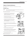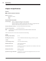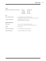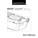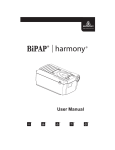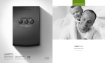
1
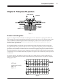
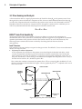
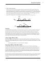
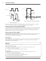
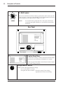
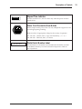
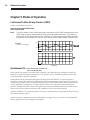
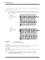
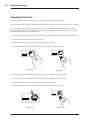
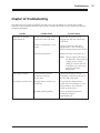
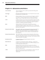
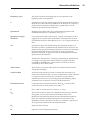
VENTILATORY SUPPORT SYSTEM
Featuring
¤
¤
S/T
BiPAryPSupport System
®
Ventilato
Clinical Manual
BiPAP systems are the subject of one or more of U.S. Patents #5148802, #5239995, #5313937,
#5433193, Canadian Patent #2,024,477, European Patent #EP0425092, German Patent
#69021681.5-08, and other pending U.S. and foreign patents. BiPAP, Plateau, Whisper Swivel,
Comfort Flap, Spectrum, Monarch, Softcap, Quick Clip, Respironics LX, Whisper Cap, and
Auto-Trak Sensitivity are trademarks of Respironics, Inc.
336058
LK 3/16/00
i
Table of Contents
Chapter 1
General Description ............................................................................................ 1
Chapter 2
Warnings, Cautions, and Notes ........................................................................ 2
Chapter 3
Principles of Operation ...................................................................................... 5
Chapter 4
Description of Controls ...................................................................................... 9
Chapter 5
Modes of Operation .......................................................................................... 14
Chapter 6
Setting Up the BiPAP S/T System .................................................................. 18
Chapter 7
Administering Oxygen with the BiPAP S/T ................................................ 20
Chapter 8
Administering Aerosolized Medication with the BiPAP S/T System ...... 21
Chapter 9
Performance Verification ................................................................................. 22
Chapter 10
Cleaning Instructions ....................................................................................... 24
Chapter 11
Routine Maintenance ........................................................................................ 25
Chapter 12
Troubleshooting ................................................................................................ 27
Chapter 13
Abbreviations/Definitions .............................................................................. 28
Chapter 14
Specifications ..................................................................................................... 30
Limited Warranty ...................................................................................................................... 32
ii
General Description
Chapter 1 General Description
The BiPAP S/T System
The BiPAP S/T is a low-pressure, electrically driven ventilation system with electronic pressure control.
The unit’s pressure controls are adjusted to deliver pressure support for patient ventilatory assistance.
The BiPAP S/T System is primarily intended to augment patient ventilation by supplying pressurized air
through a patient circuit. It senses the patient’s breathing effort by monitoring airflow in the patient
circuit and adjusts its output to assist in inhalation or exhalation. This assistance is provided by the
administration of two levels of positive pressure. During exhalation, pressure is variably positive or near
ambient. The inspiratory level is variably positive and is always higher than the expiratory level.
The Respironics BiPAP S/T System responds to changes in patient flow rates that indicate movement to
inhalation and exhalation. It can perform reliably in sensing the patient’s breathing efforts, even with the
presence of most leaks in the patient circuit. Automatic adjustment of the trigger threshold in the
presence of leaks make the System ideal for mask-applied ventilation assistance.
The BiPAP S/T senses air flow in the patient circuit by using a flow transducer in conjunction with the
patient air outlet. The flow signal is composed of flow into the patient’s lungs and flow due to leaks in the
patient circuit. This flow data is continually processed and adjustments are automatically made to trigger
thresholds. The adjustments provide high sensitivity to inspiratory effort and rapid adjustment for
changing leaks while minimizing inspiratory pressure lockup or auto-triggering.
The System can operate in the following four modes. In all of the modes, the prescribed setting for each
functional control must be determined by the physician/technician based on appropriate patient testing
and monitoring of the necessary physiologic parameters.
Spontaneous (S) Mode
The unit cycles between the Inspiratory Positive Airway Pressure (IPAP) and Expiratory
Positive Airway Pressure (EPAP) levels in response to patient triggering. The patient
determines the respiratory rate.
Spontaneous/Timed (S/T) Mode
The unit cycles between the IPAP and EPAP levels in response to patient triggering. If
the patient fails to initiate an inspiration, the unit will cycle to IPAP based on a preset
interval determined by the Breaths Per Minute (BPM) control.
Timed (T) Mode
The unit cycles between the IPAP and EPAP levels based solely on the timing intervals as
determined by the rate (BPM) and inspiratory time (% IPAP) controls. The patient may
superimpose spontaneous respirations over the IPAP and EPAP levels.
Continuous Positive Airway Pressure (CPAP)
With the Function Selector Knob set in either the IPAP or EPAP position, the pressure set
on the corresponding dial will be delivered continuously.
Note:
Occasionally, cosmetic changes may be made to a product that do not affect its performance
or specifications. These changes do not warrant reprinting the manual. Illustrations are for
reference only.
1
2
Warnings, Cautions, and Notes
Chapter 2 Warnings, Cautions, and Notes
Warning:
Caution:
Note:
Indicates the possibility of injury to the patient or the operator.
Indicates the possibility of damage to the device.
Places emphasis on an operating characteristic.
Warnings
•
This manual serves as a reference. It should be used in conjunction with the instructions and
protocol set by the physician at the institution where the device is being used. The instructions in
this manual are not intended to supersede established medical protocols regarding the use of
assist ventilators.
•
The BiPAP S/T System is an assist ventilator and is intended to augment the ventilation of a
spontaneously breathing patient. It must not be used as a life support ventilator. It is not
intended to provide the total ventilatory requirements of the patient.
•
The BiPAP S/T should not be applied to patients who are incapable of maintaining
life-sustaining ventilation in the event of malposition of the patient interface.
•
The BiPAP S/T is intended for use on patients one year of age and older.
•
The BiPAP S/T is intended for use with a Respironics, Inc. approved patient circuit only. A
Respironics approved circuit consists of :
–
smooth inner lumen tubing,
–
an exhalation device such as the Whisper Swivel® II, Plateau™ Exhalation Valve, or
Respironics Disposable Exhalation Port Assembly, and
–
a noninvasive patient interface (nasal mask, mouthpiece, or full face mask).
Additional accessories may be added to the circuit to meet specific needs. Every time changes are
made to the circuit configuration, the delivered pressures must be monitored at the patient
connection with the unit cycling. If using other patient circuits, they must have a continuous leak
exhalation port with flow comparable to Respironics exhalation ports.
•
The continuous flow exhalation port (e.g., Whisper Swivel II) is designed to exhaust patient
exhalation from the patient circuit. Continuous flow is required for safe operation. Do Not Block
or Otherwise Try to Seal the Vents on the Exhalation Port.
•
In situations where risk of contamination between the user and the BiPAP unit is high, a low
resistance, main flow bacteria filter should be placed in-line between the unit and the patient.
•
All patient settings must be determined via appropriate diagnostic testing and monitoring by the
prescribing physician. Delivered pressures must be monitored at the patient connection with the
unit cycling.
•
Each time changes are made to the circuit configuration, confirm that delivered pressures are
adequate for patient management.
•
Explosion Hazard - Do not use the BiPAP S/T System in the presence of flammable anesthetics.
•
Oxygen supports combustion. Oxygen should not be used while smoking or in the presence of an
open flame.
•
Do Not add oxygen to the front of a BiPAP unit (at the inlet filter opening).
•
BiPAP S/T System performance should be verified, as described in Chapter 9, before each new
patient is placed on the system.
•
If the BiPAP S/T begins to function incorrectly, discontinue use and contact your health care
dealer or Respironics, Inc.
Warnings, Cautions, and Notes
Warnings continued
•
The addition of accessories to the patient circuit (e.g., heated humidifier, main flow bacteria filter,
water traps, and additional tube lengths) affects pressure and flow delivery at the patient
connection. Clinical assessment must confirm that the delivered pressures and flows are
adequate for patient management when circuit accessories are used. It may be necessary to
increase pressure delivery to compensate for the increased resistance of the circuit.
•
When the BiPAP S/T is used with a heated humidifier, that manufacturer’s specifications should
be checked to confirm that the humidifier will function correctly in the presence of the
continuous flow from the BiPAP S/T System. Always position the humidifier lower than both the
BiPAP unit and the patient.
•
When the BiPAP S/T System is used with a heated humidifier, water traps must be placed in the
patient circuit.
•
As with any pressure-limited ventilation system, particular caution must be exercised in caring
for patients with changing respiratory system compliance and resistance, because this may affect
the adequacy of ventilatory support.
•
Wiring connections and adjustments should be performed by authorized service personnel only.
•
Repairs and adjustments must be performed by experienced personnel who are fully acquainted
with this equipment. Service done by inexperienced, unqualified personnel or installation of
unauthorized parts could cause personal injury, invalidate the warranty, or result in costly
damage. Contact Respironics, Inc. or your health care dealer if the unit fails to meet
performance specifications.
•
To avoid electrical shock, disconnect the electrical supply before changing the fuses.
•
Replace fuses with those of the same type and rating only.
•
To avoid electrical shock, unplug the BiPAP unit before cleaning it.
Cautions
•
Federal law restricts this device to sale by or on the order of a physician.
•
For pressure monitoring, use only tubing with a smooth inner lumen.
•
When transporting or storing the BiPAP S/T, take precautions to avoid exposure to temperature
extremes. If exposure to such temperatures occurs, allow the unit to come to room temperature
before turning it on.
•
Position the unit on its base or rear panel for proper operation.
•
Ensure that the voltage selector switch is set according to local line voltage and the proper fuses
are used.
•
When using Respironics smooth inner lumen tubing without a heated humidifier, the overall
length of the tubing should not exceed 12 feet.
•
Remove the mask before turning the BiPAP unit off.
•
Electromagnetic emissions: BiPAP S/T Systems have been tested and shown to comply with
FCC Class B Subpart 15.J requirements.
•
Verifying the operation of medical monitoring equipment used near the BiPAP S/T is
recommended to ensure that any electromagnetic interference produced by the unit does not
affect the function of the monitoring equipment.
3
4
Warnings, Cautions, and Notes
Notes
•
The Inspiratory Positive Airway Pressure (IPAP) and Expiratory Positive Airway Pressure
(EPAP) controls are electrically coupled. The unit will not deliver an EPAP level that is higher
than the set IPAP level. If the EPAP control is set higher than IPAP, the unit will be locked to the
IPAP setting and the IPAP Light Emitting Diode (LED) will remain lit.
•
Circuit tubing with a smooth inner lumen and a nominal diameter of 22 mm is recommended.
Tubing with a corrugated inner lumen will cause a pressure drop from the blower outlet to the
patient connection. This may affect the unit’s ability to deliver the maximum pressure.
•
Heat and moisture exchangers should not be used with the BiPAP S/T. Testing has shown that
the ability of the unit to maintain the prescribed pressure is significantly affected by the addition
of a heat and moisture exchanger to the patient circuit.
Additional Warnings, Cautions, and Notes are located throughout this manual.
Contraindications
The following may contraindicate the use of a BiPAP S/T System:
a.
Patients with or susceptible to pneumothorax or pneumomediastinum should be monitored
closely when applying positive pressure. Pre-existing bullous lung disease may represent a
relative contraindication.
b. Hypotension induced by positive pressure ventilation.
c.
A history of allergy or hypersensitivity to the mask material where the risk from allergic reaction
outweighs the benefit of ventilatory assistance.
d. Aspiration of gastric contents. Exercise caution when applying a full face (nasal/oral) mask to
patients because of the increased possibility of aspirating gastric contents. This is particularly true
in patients who are at risk for or who have been vomiting. In these patients, placement of a
nasogastric suction tube may be advisable prior to the application of a full face mask.
e.
Acute sinusitis or otitis media. Although it is not necessary in most situations, nasal positive
pressure therapy may need to be suspended temporarily in some patients with acute sinusitis or
otitis media.
f.
Patient’s inability to maintain a patent airway or to adequately clear secretions.
g. Life-threatening or potentially life-threatening epistaxis.
h. Patients without an intact respiratory drive.
Patient Warnings
•
Advise the patient to report any unusual chest discomfort, shortness of breath, or severe
headache immediately.
•
If using a full face mask, advise the patient not to eat or drink two to three hours prior
to bedtime.
•
The following are potential side effects of noninvasive positive pressure ventilation:
–
Ear discomfort
–
Conjunctivitis
–
Skin abrasions due to noninvasive interfaces
–
Aerophagia (gastric distention)
Principles of Operation
Chapter 3 Principles of Operation
BiPAP EXHAUST
VALVE DISC
AIR TO
PATIENT
AIR FROM
BiPAP UNIT
COIL
N
S S
N
PRESSURE
CHAMBER
MAGNET
Figure 1
Pressure Controlling Valve
Figure 1 is a diagram of the electrically controlled pressure valve. Based on the setting of the IPAP and
EPAP controls, the control circuit adjusts the electrical current in the valve coil. The electric current in the
coil, in combination with the magnetic field from the magnet, produces a force on the valve disc. The
force that the coil and magnet generate must equal the force created by the air pressure in order to
maintain a stable pressure level.
As the patient breathes, flow into the valve increases and decreases. This tends to cause swings in the
force generated by the air pressure inside the valve. As changes from the preset pressure are sensed, the
electrical current automatically adjusts the disc to increase or decrease the amount of air vented from the
pressurized valve chamber. This allows the valve to maintain the appropriate pressure (whether IPAP or
EPAP) by adding flow to the circuit or by dumping it at the internal valve outlet. Because the monitoring
is continuous, the valve module immediately responds to changes in flow to deliver the preset pressure at
a stable level.
As shown in Figure 2, this method of control provides very stable pressures, permits rapid changes in
pressures to the preset IPAP/EPAP levels, and maintains the preset pressures in the presence of rapidly
changing flow rates.
60 L/min.
Vest
0
SETTINGS:
60 L/min.
Spontaneous Mode (S)
IPAP = 15
EPAP = 5
1 second
5 cm H2O
P
1 second
Figure 2
5
6
Principles of Operation
3.2 Flow Sensing and Analysis
A flow transducer derives a signal proportional to the Total Flow Rate (Vtot) in the patient circuit. From
this signal, the system calculates the component of flow, known as the Estimated Patient Flow Rate (Vest),
as well as the component derived from leaks in the patient circuit, known as the Estimated Leak Flow
Rate (Vleak). Patient circuit leaks are composed of flow through the continuous flow exhalation port as
well as any unintentional leaks that may be present around the interface seal.
Vtot = Vest + Vleak
BiPAP® Auto-Trak Sensitivity™
An important characteristic of the BiPAP S/T unit is its ability to recognize and compensate for
unintentional leaks in the system and to automatically adjust its trigger and cycle algorithms to maintain
optimum performance in the presence of leaks. This feature is known as Auto-Trak Sensitivity. The
following sections examine this function in detail by describing the leak tolerance function
and sensitivity.
Leak Tolerance
Leak tolerance is the unit's ability to respond to changes in leaks. The BiPAP S/T uses two mechanisms to
identify and adjust to leaks.
1. Expiratory Flow Rate Adjustment
At end expiration, the total flow in the patient circuit should equal the baseline leak (Vleak), which
consists of intentional (exhalation port) and unintentional (mask, mouth) leaks. Once the unit has
been in EPAP for 5 seconds, the total flow is compared to the originally established value of Vleak. At
this point, the BiPAP S/T flow sensing circuit makes the assumption that the patient's flow is zero, so
that the total circuit flow, Vtot , should be equal to Vleak.
Thus, under this condition of assumed zero patient flow, if Vtot is not equal to Vleak, the BiPAP S/T will
adjust its calculation of the baseline leak. Figure 3 shows graphically how Vleak is adjusted in the case of
an increase in leak.
INSPIRATION
ORIGINAL
BASELINE
(Vleak)
CYCLE TO EPAP
NEW BASELINE
END EXPIRATION
ADDITIONAL
LEAK
Spontaneous Trigger
TOTAL FLOW
(Vtot)
5.0 SECONDS
Adjustment of
(Vleak)
Figure 3: Expiratory Flow Rate Adjustment
Principles of Operation
2. Tidal Volume Adjustment
Inspiratory (VTI) and expiratory (VTE) tidal volumes are determined by the estimated patient flow,
and compared on a breath-by-breath basis. If the measured volumes during inspiration differ from
expiration, the difference in volume is assumed to be due to an unintentional circuit leak. The baseline
•
(Vleak) is adjusted in the appropriate direction to reduce the difference in VT - VT on the next breath.
I
E
This prevents abrupt changes in sensitivity based on random changes in the breathing pattern, and
•
allows the baseline (Vleak) to accommodate to the new breathing pattern.
Figure 4 shows graphically how tidal volume is adjusted in the case of a change in leak.
Additional
Leak
Introduced
Vest
0
Volume
Adjustment
VT
0
Figure 4: Tidal Volume Adjustment
Sensitivity
An essential feature of the BiPAP S/T while operating in the S and S/T modes is its ability to effectively
sense spontaneous breathing efforts, which causes the ventilator to trigger to IPAP and cycle to EPAP.
Because no preset sensitivity threshold can ensure patient and machine synchrony with changing
breathing efforts and circuit leaks, the BiPAP S/T continuously tracks patient breathing patterns and
automatically adjusts sensitivity thresholds to ensure optimum sensitivity as breathing patterns change
or as circuit leaks change. The algorithms used to ensure optimum sensitivity are the Volume Trigger,
Shape Signal, and the Spontaneous Expiratory Threshold (SET).
Volume Trigger (EPAP to IPAP)
The volume trigger is one method used to trigger IPAP during spontaneous breathing in the S and S/T
•
modes. The volume trigger threshold is 6 cc of accumulated volume above the baseline leak (Vleak). When
•
patient effort generates inspiratory flow causing 6 cc of volume to accumulate above baseline (Vleak), IPAP
is triggered:
•
Volume trigger threshold = 6 cc volume above Vleak baseline
Shape Signal (EPAP to IPAP; IPAP to EPAP)
The shape signal is another method used to trigger IPAP and/or cycle off IPAP to EPAP during
spontaneous breathing in the S and S/T modes. This signal continuously tracks patient inspiratory and
expiratory flow rate and adjusts the spontaneous trigger and cycle thresholds for optimum sensitivity.
The shape signal appears as a shadow image of the patient's actual flow. The shape signal functions as a
sensitivity threshold at either inspiration or expiration. When the patient's flow rate crosses the shape
signal, the unit changes pressure levels. Figure 5 illustrates how the shape signal is superimposed onto
the actual waveform to trigger and cycle off IPAP.
The shape signal is created by offsetting the signal from the actual patient flow by 15 L/min and delaying
it for a 300 msec period. This intentional delay causes the shape signal to be slightly behind the patient's
flow rate. A sudden change in patient flow will cross the shape signal, causing the pressure level
to change.
7
8
Principles of Operation
IPAP
IPAP
PRESSURE
PRESSURE
EPAP
EPAP
Shape
Signal
FLOW
Cycle to
EPAP
Crossover
Point
Spontaneous
Expiratory
Threshold
FLOW
Estimated
Patient
Flow
Trigger to
IPAP
Crossover
Point
Figure 6: Spontaneous Expiratory Threshold
Figure 5: Shape Signal
Tracking the patient's flow pattern with the shape signal provides a sensitive mechanism to trigger to
IPAP or cycle to EPAP in response to changing breathing patterns and circuit leaks.
Spontaneous Expiratory Threshold (IPAP to EPAP)
A second method used to cycle off IPAP during spontaneous breathing in the S and S/T modes is called
Spontaneous Expiratory Threshold (SET). The SET is an electronic signal that rises in proportion to the
inspiratory flow rate on each breath. When the Spontaneous Expiratory Threshold (SET) and actual
patient flow value are equal, the unit cycles to EPAP.
Maximum IPAP Time (IPAP to EPAP)
A maximum IPAP time of 3.0 seconds acts as a safety mechanism to limit the time spent at the IPAP level
during spontaneous breathing in the S and S/T modes. Once the time limit is reached, the unit
automatically cycles off IPAP to the EPAP level.
Flow Reversal
As flow begins to decrease during IPAP, a flow reversal can occur due to a large leak around the mask or
because the patient's mouth is open. When the BIPAP S/T unit senses this flow reversal, the unit
automatically cycles to the EPAP level.
Summary
The sensitivity criteria for spontaneous breathing in the S and S/T modes can be summarized as follows:
Spontaneous Trigger to IPAP
A transition from EPAP to IPAP will occur when one of the following conditions is met:
• patient flow exceeds the shape signal
•
• 6 cc inspired volume accumulates above baseline flow (Vleak)
Cycle to EPAP
The transition from IPAP to EPAP will occur when one of the following conditions is met:
• patient flow is less than the shape signal
• Spontaneous Expiratory Threshold (SET) is achieved
• a 3.0 second maximum IPAP time has occurred (safety feature)
• flow reversal occurs during IPAP (safety feature)
Description of Controls
Chapter 4 Description of Controls
BiPAP S/T System
Front Panel
®
®
®
BiPAP S/T
I
0
Ventilatory Support System
I
Power Switch
Turns the electrical power to the unit on and off.
0
Air Outlet
Accepts a 22 mm connector for smooth inner lumen tubing; also accepts a
main flow bacteria filter.
9
10
Description of Controls
Control Panel
!
WARNING
This is a NON-CONTINUOUS
ventilator and is intended to augment
patient breathing. IT MUST NOT BE
USED AS A LIFE SUPPORT VENTILATOR.
IPAP
10 12
8
14
16
6
18
4
20
10
IPAP
EPAP
50
20
24
EPAP
8
16
12
12
70
30
8
14
6
16
4
18
30
4
BPM
20
Spontaneous (S)
Spontaneous / Timed (S/T)
Timed (T)
10
90
% IPAP
Functional in
Timed (T) Mode Only
Function Selector Knob
IPAP
EPAP
Spontaneous (S)
Spontaneous/Timed (S/T)
Timed (T)
The position of the indicator on the knob
determines which function or mode will be
active. The function selector knob has five
discrete positions.
IPAP Position: Inspiratory Positive Airway
Pressure. With the Function Selector Knob in
this position the unit delivers CPAP at the level
indicated by the IPAP pressure control. The
EPAP setting is not active.
EPAP Position: Expiratory Positive Airway
Pressure. With the Function Selector Knob in
this position, the unit delivers CPAP at the
level indicated by the EPAP pressure control.
The IPAP setting is not active.
Spontaneous (S) Mode: When set at this
mode, the adjacent LED is illuminated. Active
controls are IPAP and EPAP.
Spontaneous/Timed (S/T) Mode: When set at
this mode, the adjacent LED is illuminated.
Active controls are IPAP, EPAP, and BPM.
Timed (T) Mode: When set at this mode, the
adjacent LED is illuminated. Active controls
are IPAP, EPAP, BPM, and % IPAP.
Description of Controls
Controls
IPAP Control
IPAP
Inspiratory Positive Airway Pressure.
10 12
14
8
16
6
18
4
20
Active when the Function Selector Knob is in any of these four positions:
IPAP, S, S/T, or T.
When the unit is delivering IPAP, the adjacent LED is illuminated.
Range = 4 - 20 cm H2O.
EPAP Control
EPAP
10
12
8
Expiratory Positive Airway Pressure.
14
6
16
4
18
20
Active when the Function Selector Knob is in any of these four positions:
EPAP, S, S/T, or T.
When the unit is delivering EPAP, the adjacent LED is illuminated.
Range = 4 - 20 cm H2O.
Note:
16
The IPAP and EPAP controls are electrically coupled. The unit will not
deliver a higher EPAP than IPAP level. If the EPAP control is set higher
than the IPAP control, the BiPAP unit will be locked to the IPAP
setting and the IPAP LED will remain lit. This is active throughout the
S, S/T, and T settings on the Function Selector Knob.
BPM Control
20
12
24
Breaths Per Minute: Active when the Function Selector Knob is positioned in
either the S/T or the T mode. Range = 4 - 30 BPM.
8
30
4
BPM
S/T Mode—The BPM control sets a time interval for delivery of a breath by the
BiPAP S/T System. If the patient initiates a spontaneous breath, the BPM timer
is reset. If the patient does not initiate a spontaneous IPAP trigger within the
interval set by the BPM control, the BiPAP unit will initiate a timer triggered
breath. The BPM timer is reset with each transition from EPAP to IPAP
whether the transition was triggered by the patient or by the BPM control
setting. The adjacent LED will illuminate, indicating timer-initiated IPAP
transitions.
T Mode—All triggering from EPAP to IPAP is controlled by the BPM timer.
The BPM LED is not active. The % IPAP control must also be set.
11
12
Description of Controls
50
% IPAP Control
70
30
10
90
% IPAP
Active when the Function Selector Knob is positioned in the T mode only. This
control works in conjunction with the BPM control and determines the fraction
of the respiratory cycle spent in IPAP. Range = 10 - 90%
NOTE:
For % IPAP values greater than 50%, time spent at IPAP will
exceed the time spent at EPAP (i.e., an inverse I:E ratio will be
delivered).
Rear Panel
! Warnings and Cautions
®
BiPAP
Ventilatory Support System
®
®
115
230
0000000h
Model 330000
! Warnings and Cautions
®
BiPAP
Ventilatory Support System
Serial No.
000000
Control Panel Door
Contains the warnings, cautions, and electrical information
necessary for safe operation of the BiPAP S/T System.
®
®
When using the Detachable Control Panel, the door may be
left closed during operation.
Voltage Selector Switch
230
115
Set this switch to the appropriate line voltage.
U.S.A. and Canada - 115 Volts
European and other countries - Check the country’s line voltage
requirements for the correct setting.
Description of Controls
Elapsed Time Indicator
0000000h
Provides resolution to 1/10 hour. Runs only when the power switch is
turned ON (I).
Power Cord Connector/Fuse Holder
Electrical input for the power cord. Use only a Respironics-approved cord
set with appropriate grounding.
Holds two fuses of appropriate voltage for the country of operation.
115 - 120 VAC - 800 mA, 250 V - Type AG Time Delay, 1/4” x 11/4”
230 - 240 VAC - T400 mA, 250 V, 5 x 20 mm
000000
Model/Serial Number Label
The information on the model/serial number label should be recorded
on the BiPAP Warranty Card and returned to Respironics within 10
days of purchase.
13
Modes of Operation
Chapter 5 Modes of Operation
Continuous Positive Airway Pressure (CPAP)
CPAP can be delivered as follows:
Function Selector Knob: EPAP/CPAP
Active Control: EPAP
Note:
The active pressure control being used actually indicates the level of CPAP being delivered. In the
CPAP mode, the patient breathes spontaneously at the indicated pressure level. The patient is in
total control of both rate and tidal volume. The BiPAP S/T system responds as necessary to satisfy
the patient’s flow demand and circuit leak while maintaining the preset pressure at a stable level.
Example:
CPAP = 10 cm H2O
60 L/min.
Vest
0
60 L/min.
1 second
P
5 cm H2O
14
1 second
Figure 1
Spontaneous (S): Function Selector Knob: Spontaneous (S)
Active Controls: IPAP, EPAP
In the S mode, the patient is in control of the respiratory rate. When the unit is triggered to IPAP, the
BiPAP S/T system immediately diverts flow to the patient circuit to establish the preset pressure and
satisfy the patient’s inspiratory demand.
If the patient actively participates throughout the IPAP phase, the BiPAP S/T system responds as
necessary to satisfy the patient's flow requirements while maintaining the preset pressure. Under these
conditions, the patient is active in determining inspiratory time and tidal volume. If the patient does not
actively participate, the BiPAP S/T system responds with the flow required to maintain the preset
pressure. The delivered tidal volume will depend upon the pressure differential between the IPAP and
EPAP levels and the combined resistance and compliance of the circuit and the patient.
In EPAP, the BiPAP S/T system responds as necessary to maintain the preset pressure in the presence of
the patient's expiratory flows.
See the Principles of Operation section for information on trigger and cycle criteria for assisted breaths.
Refer to Figures 2 and 3 for examples and diagrams.
Modes of Operation
Example:
IPAP = 15 cm H2O
EPAP = 10 cm H2O
60 L/min.
Vest
0
60 L/min.
1 second
5 cm H2O
P
1 second
Figure 2
Example:
IPAP = 15 cm H2O
EPAP = 4 cm H2O
60 L/min.
Vest
0
60 L/min.
1 second
5 cm H2O
P
1 second
Figure 3
Spontaneous/Timed
(S/T):
Function Selector Knob: Spontaneous/Timed (S/T)
Active Controls: IPAP, EPAP, BPM
In the S/T mode, the patient is in control of the respiratory rate as long as it exceeds the BPM setting. The
BPM control determines the minimum respiratory rate delivered by the unit. If the unit does not detect a
spontaneous trigger within the interval determined by the BPM setting, it will activate a timed trigger to
the IPAP level. Once triggered to IPAP, the balance of the cycle continues as in the S mode. Any IPAP
trigger, whether spontaneous or timed, resets the interval timer.
If the patient actively participates throughout the IPAP phase, the pressure system responds as necessary
to satisfy the patient’s flow requirements while maintaining the preset pressure. Under these conditions,
the patient and the pressure differential determine inspiratory time and tidal volume. If the patient does
not actively participate, the BiPAP S/T system responds with the flow required to maintain the preset
pressure. The delivered inspiratory time and tidal volume will be dependent upon the pressure
differential between the IPAP and EPAP levels and the combined resistance and compliance of the
circuit and the patient.
15
Modes of Operation
See the Principles of Operation section for information on trigger and cycle criteria for assisted breaths.
Refer to Figures 4 and 5 for examples.
Note:
When using a recorder, timer triggered breaths in the S/T mode can be identified by an event
•
marker on the Vest channel. On the recording, there is a deflection below baseline at the initiation
of the inspiratory flow.
Example:
IPAP = 15 cm H2O
EPAP = 10 cm H2O
BPM = 10
60 L/min.
Vest
0
60 L/min.
2 seconds
5 cm H2O
P
2 seconds
Figure 4
Example:
IPAP = 15 cm H2O
EPAP = 4 cm H2O
BPM = 12
60 L/min.
Vest
0
60 L/min.
2 seconds
P
5 cm H2O
16
2 seconds
Figure 5
Timed (T):
Function Selector Knob: Timed (T)
Active Controls: IPAP, EPAP, BPM, %IPAP
Cycle to IPAP:
The interval timer triggers movement to the IPAP level based on the BPM setting. The %IPAP control
determines what percent of the respiratory cycle is spent at the IPAP level.
Cycle to EPAP:
Upon completion of the %IPAP period, the unit cycles to EPAP and remains there until the interval timer
triggers movement to IPAP.
Note:
In the T mode, all movement between IPAP and EPAP is controlled by the timing intervals
determined by the BPM and %IPAP settings. Changes in delivered pressure levels do not
occur based on changes in patient flow.
Modes of Operation
In the T mode, the control panel settings determine all movement between the IPAP and EPAP levels.
When the interval timer triggers movement to IPAP, the electronic system immediately diverts flow to
the patient circuit to establish the IPAP level. The actual flow rate will be dependent upon the pressure
differential between the IPAP and EPAP levels and the combined resistance and compliance of the circuit
and the patient.
If the patient actively participates throughout the IPAP phase, the BiPAP S/T system responds as
necessary to satisfy the patient’s flow requirements while maintaining the preset pressure.
Under these conditions, patient effort, %IPAP, and the pressure differential determine the tidal volume. If
the patient does not actively participate, the BiPAP S/T system responds with the flow required to
maintain the preset pressure throughout the IPAP period. The delivered tidal volume will be dependent
upon the interaction of three components:
1.
The combined resistance and compliance of the circuit and the patient.
2.
The pressure differential between the IPAP and EPAP levels.
3.
The length of time spent at the IPAP level as determined by the BPM and %IPAP settings.
Note:
The patient may superimpose spontaneous respirations over the delivered IPAP or EPAP levels at
any point in the T mode. The BiPAP S/T system will respond with flow proportional to the patient’s
demand in order to maintain the preset pressure.
Warning:
The BiPAP S/T system should not be applied to patients who are incapable of maintaining
life-sustaining ventilation in the event of a circuit disconnection or malposition of the
patient interface.
Warning:
When operating this device in the Timed Mode with %IPAP values greater than 50%, time
spent at IPAP will exceed the time spent at EPAP (i.e., an inverse I:E ratio will be delivered). It is
important to monitor patient comfort level because increased inspiratory time exceeds the
decreased expiratory time.
60 L/min.
Vest
0
60 L/min.
2 seconds
P
5 cm H2O
Example:
IPAP = 15 cm H2O
EPAP = 10 cm H2O
BPM = 10
%IPAP = 30
2 seconds
Figure 6
60 L/min.
Vest
0
60 L/min.
2 seconds
P
5 cm H2O
Example:
IPAP = 15 cm H2O
EPAP = 4 cm H2O
BPM = 12
%IPAP = 40
2 seconds
Figure 7
17
18
Setting Up the BiPAP S/T System
Chapter 6 Setting Up the BiPAP S/T System
1.
See Figure 16. Connect one end of the patient tubing to the outlet port on the front of the BiPAP unit.
In situations where risk of contamination between the user and the BiPAP unit is high, a low
resistance, main flow bacteria filter should be placed in-line between the unit and the patient.
BiPAP Unit
Outlet Port
®
BiPAP S/T
Main Flow
Bacteria
Filter
(Optional)
Tubing
Figure 16
Note:
If a bacteria filter is used, it must be positioned in the circuit so that it is filtering air directly from
the unit. If a humidifier is also used, the bacteria filter should not be placed in the circuit between
the outlet of the humidifier and patient, because this can cause an increase in filter resistance.
The addition of a low resistance main flow bacteria filter does not affect the trigger
sensitivity of the system. Depending on the degree of resistance imposed by the filter, the pressure
stability (the ability of the unit to maintain the delivered pressure within specified tolerances) may
be affected. The filter must remain clean and dry to minimize circuit resistance. The
main flow bacteria filter should be replaced in accordance with the manufacturer's
specifications and instructions.
The bacteria filter should be in-line when the pressure settings are determined. If a filter is added to
a system already in use, observe the patient to determine whether the pressure settings should be
adjusted to compensate for any pressure drop resulting from the filter.
2.
See Figure 17. Assemble the patient circuit as shown below.
Warning:
A continuous flow exhalation port (i.e., Whisper Swivel II) is designed to exhaust patient
exhalation from the patient circuit. Continuous flow is required for safe operation. Do Not
Block or Otherwise Try to Seal the Gas Vents on the Exhalation Port.
Reusable Circuit
Disposable Circuit
Rotating
Connector
Proximal
Pressure Line
Assembly
Rotating
Connector
Whisper
Swivel II
Exhalation
Port
Proximal
Pressure Line
Assembly
Tubing
Tubing
Figure 17
Setting Up the BiPAP S/T System
Warning:
Each time changes are made to the circuit configuration, confirm that delivered pressures are
adequate for patient management.
Warning:
The addition of accessories to the patient circuit (e.g., heated humidifier, bacteria filter, water
traps, and additional tube lengths) affects pressure and flow delivery at the patient
connection. Clinical assessment must confirm that the delivered pressures and flows are
adequate for patient management when circuit accessories are used. It may be necessary to
increase pressure delivery to compensate for the increased resistance of the circuit.
Note:
Heat and moisture exchangers should not be used with the BiPAP S/T System. Testing has
shown that the ability of the unit to maintain the prescribed pressure is significantly affected
by the addition of a heat and moisture exchanger to the patient circuit.
See Figure 18. Plug the electrical cord into the power
connector on the back of the unit.
4.
See Figure 19. Make sure the voltage selector switch on the
back of the unit is set correctly.
United States and Canada setting: 115 V
European and other countries: Check the country’s line
voltage requirements for the correct setting.
5.
Power Cord
Connector
Figure 18
115
0
23
See Figure 20. Make sure the ON/OFF switch is OFF (0), then plug
the electrical cord into a three-prong outlet.
115
230
3.
Note:
6.
In the United States and Canada, the use of a three-prong to
two-prong adapter or extension cord is not recommended.
115
230
Turn the unit on, occlude the outlet port, and confirm the presence
of flow from the exhalation port.
Figure 19
Figure 20
19
20
Administering Oxygen with the BiPAP S/T System
Chapter 7 Administering Oxygen with the BiPAP S/T
Warning:
Oxygen should be administered only on the order of a physician.
Warning:
Oxygen supports combustion. Oxygen should not be used while smoking or in the
presence of an open flame.
Warning:
Do not add oxygen to the front of the BiPAP S/T System (at the inlet filter opening).
Note:
When using oxygen, turn the BiPAP S/T System ON (I) before turning on the oxygen source.
The oxygen should then be turned off before the unit is turned OFF (0).
To add oxygen to the circuit, a controlled, low-flow source is needed (less than 15 L/min).
•
Attach the oxygen tubing to one of the sample ports on or near the patient’s interface, as indicated
in Figure 21a.
•
Do not use a flow rate greater than 15 L/min.
•
A main flow bacteria filter must be inserted between the air outlet on the unit and the circuit
tubing (See Figure 21b).
•
Turn the BiPAP S/T System on before turning on the oxygen supply.
•
Turn off the oxygen supply before turning the BiPAP S/T System off.
•
If power to the BiPAP S/T System has been turned off for any reason before the oxygen supply is
turned off, allow the oxygen to dissipate from the unit before turning the BiPAP S/T System on.
When adding oxygen to the patient circuit, the liter flow is gradually adjusted until the patient’s
oxygenation needs are adequately met. If adequate oxygenation cannot be acheived, an alternate method
of ventilatory support should be considered.
If the method of oxygen administration is changed at any time, or as patient status changes, the patient
should be monitored to make sure that his or her oxygenation level is sufficient.
Sample Port
BiPAP Unit
Oxygen Tubing
to Oxygen Source
Outlet Port
T
BiPAP S/
®
Main Flow
Bacteria
Filter
(Optional)
Figure 21a
Figure 21b
Tubing
Administering Aerosolized Medication with the BiPAP S/T System
Chapter 8 Administering Aerosolized Medication with
the BiPAP S/T System
Small volume nebulizers or adaptors, which allow the use of metered dose inhalers, may be added to the
patient circuit. If a small volume nebulizer is used, testing has shown that the liter flow used to drive the
nebulizer does not affect the BiPAP S/T System functions.
The aerosol delivery system used should be added to the patient circuit on the patient side of the
continuous flow exhalation port. This will minimize the impact of the continuous circuit flow on the
aerosol treatment. If a main flow bacteria filter is not being used, one should be added to the BiPAP outlet
during the treatment period to prevent any of the aerosolized medication from entering the BiPAP S/T
System via the patient circuit.
Inspect the exhalation device after each aerosol administration to insure that the ports have not been
occluded by the medication. If necessary, clean or replace the exhalation device.
Warning:
Aerosolized medications may collect in the exhalation port. To avoid an obstruction to flow,
inspection of the exhalation port is essential during and after medication delivery.
21
22
Performance Verification
Chapter 9 Performance Verification
Warning:
Performance verification should be performed prior to each patient use of the
BiPAP System.
Note:
For performance verification, Respironics recommends use of a manometer capable of
reading pressures in centimeters of water.
1.
Connect the patient circuit following the Set-up Instructions in this manual. Connect the
proximal pressure tubing to one of the pressure ports on the mask or exhalation valve.
2.
Connect the remaining end of the proximal pressure tubing to the manometer.
3.
Adjust the settings on the control panel as follows:
Function Selector Knob: IPAP
Controls: IPAP 4 cm H2O
EPAP 4 cm H2O
BPM 10
%IPAP 30
4.
Turn the BiPAP unit ON (I) and allow it to warm up for at least 15 minutes prior to
performance verification.
5.
a.
b.
c.
d.
e.
f.
g.
h.
Occlude the circuit outlet.
Verify that the Function Selector Knob is set at the IPAP position.
Verify that the appropriate LED is illuminated.
Verify that the IPAP reading is 4 cm ± 2 cm H2O.
Adjust the IPAP setting to 10, 15, and then 20 cm H2O and verify corresponding readings.
Set the IPAP control to the maximum setting position.
Set the Function Selector Knob to the EPAP position and repeat Steps c, d, and e.
Set the EPAP control to 5 cm H2O and the IPAP control to 10 cm H2O.
6.
a.
b.
c.
d.
Set the Function Selector Knob to the S mode.
Verify that the appropriate mode LED is illuminated.
Create a small leak to simulate a spontaneous trigger.
Observe that the unit cycles to IPAP and that the IPAP control illuminates. Verify that the
unit cycles to IPAP and remains there for approximately three seconds before cycling back to
EPAP. Once the unit cycles to EPAP, it should remain there for approximately 0.5 seconds
before cycling to IPAP. The unit will cycle between IPAP and EPAP up to five times.
Totally occlude the circuit.
e.
7.
a. Set the Function Selector Knob to the S/T mode.
b. Verify that the appropriate LED is illuminated.
c. Observe that the unit cycles between IPAP and EPAP. Observe that when the unit cycles
from EPAP to IPAP, the BPM LED illuminates. (The BPM LED may or may not remain
illuminated for the total cycle.)
d. When the DCP is in the EPAP mode (the EPAP LED is illuminated) with the BPM LED
illuminated, allow a small mask leak to simulate a spontaneous trigger. Observe that the
BPM LED does not illuminate.
e. Re-establish the mask seal.
Performance Verification
8.
a.
b.
c.
d.
e.
f.
g.
Set the Function Selector Knob to the T mode.
Verify that the appropriate LED is illuminated.
Verify that the cycling is per control settings. Time the intervals to verify the function.
Verify that the BPM setting is 10 and change the % IPAP setting to 50.
Observe that the cycling time agrees with the control settings.
Change the BPM setting to 15.
Observe that the cycling times agree with the control settings.
If all of the parameters are within the stated operating specifications, the system is ready for
patient application.
Adjust the settings to the appropriate level for patient application prior to putting the circuit
on the patient.
Warning:
If the BiPAP S/T System fails to perform within the stated specifications, it should be referred
for service.
23
24
Cleaning Instructions
Chapter 10 Cleaning Instructions
Cleaning the BiPAP S/T System
Caution:
Unplug the BiPAP S/T System before cleaning it. Do not immerse it in water or allow any
liquid to enter the cabinet. Do not get the filter wet.
Caution:
Do not clean any part of the system with alcohol or cleaning solutions containing alcohol.
Do not clean the system by steam autoclave or gas sterilization methods. These cleaning
processes may harden or deform the flexible plastic parts of the unit and adversely affect
their function.
1.
Using a cloth slightly dampened with water and a mild cleaner, wipe off the outside of the
BiPAP S/T System enclosure.
2.
Let the unit dry before plugging it in again.
Cleaning the Patient Circuit
Refer to the instructions provided with the circuit components you are using.
Routine Maintenance
Chapter 11 Routine Maintenance
Refer to the BiPAP System Service Manual for more complete maintenance information
and requirements.
Changing the Filter
Caution:
Failure to replace a dirty filter may cause high operating temperatures, reduce flow, and
reduce the output pressure of the BiPAP unit.
The white filter on the front of the unit is disposable and must be replaced after thirty days of use or
sooner if it seems especially dirty.
1.
See Figure 22. Press down (1) and pull out (2) on the
top of the Whisper Cap®. You need to press down
only about 1/8” to allow the top lip of the Whisper
Cap to clear the filter retainer.
BiP
AP
®
S/T
®
2.
Pull up (3) on the bottom of the Whisper Cap until the
bottom lip clears the filter retainer.
1
Press
down
2
3.
4.
I
0
Turn OFF (0) the unit and unplug the electrical cord
from the wall outlet and from the back of the unit.
Pull
out
See Figure 23. Locate the button in the center of the
filter holder beneath the surface of the filter. Push in
on the button and pull the filter out from all four
sides of the filter holder.
Wh
is
Caper™
p
Pull
3 up
Figure 22
®
®
®
5.
Throw away the dirty filter. The filter is not washable.
6.
See Figure 24. Center a new filter over the filter holder. Carefully push in on the center button and tuck the filter in on all
four sides.
7.
8.
BiPAP S/T
Button
Pull
Push
Release the button. The filter should be intact and fit securely,
covering the entire holder. Remove and readjust the filter, if
necessary.
Insert the bottom lip of the Whisper Cap behind
the inner bottom edge of the filter retainer.
I
0
Ventilatory Support System
Figure 23
®
®
®
9.
Simultaneously press down on the top of the Whisper Cap
and push in until the top lip of the Whisper Cap snaps into
place behind the inner top edge of the filter retainer.
10. Press in on the center of the Whisper Cap to ensure that the
Cap is seated in the filter retainer.
The filter must be in place at all times when the
BiPAP S/T System is being used.
BiPAP S/T
I
Ventilatory Support System
0
Tuck
Push
Figure 24
25
26
Routine Maintenance
Changing the Unit Fuses
If the unit is not operational when you turn it on, the fuses may need to be replaced.
The fuses are located in the back of the unit under the power cord connector. See page 13 for fuse ratings.
You may have one of two types of fuse holders. If the fuse holder has tabs on either side, as shown in
Figure 25, follow Steps 1 to 4 to replace the fuses. If the fuse holder has a tab on top, as shown in Figure
27, follow Steps 1a to 4a to change the fuses.
1.
See Figure 25. Remove the fuse holder by pinching in on the small tabs on the sides of the holder.
2.
Pull the fuse holder completely out of the unit.
3.
Replace the old fuses with new fuses of the same type and rating.
4.
See Figure 26. Push the fuse holder back into the unit until it snaps into place.
Figure 25
Figure 26
1a. See Figure 27. Use a standard screwdriver to pry the fuse holder out of the retainer.
2a. Grasp the exposed sides of the fuse holder and pull it completely out of the unit.
3a. Replace the old fuses with new fuses of the same type and rating.
4a. See Figure 28. Push the fuse holder back into the unit until it snaps into place.
Figure 27
Figure 28
Troubleshooting
Chapter 12 Troubleshooting
The table below lists common problems you may have with your BiPAP S/T System and possible
solutions to those problems. If none of the corrective actions listed seem to work, contact your medical
equipment distributor.
Problem
Unit does not operate
when turned on.
Possible Causes
Corrective Action
Power cord not firmly connected
to the unit or the wall outlet.
Check that the power cord is
plugged into the unit and into the
wall outlet.
Unit not connected to a “live”
outlet.
Check to ensure that the unit is
plugged into a “live” outlet (e.g.,
plug a working lamp into the outlet.)
Unit fuse(s) has blown.
Replace the fuses. See Section 11.2.
Note: Always replace both fuses at
the same time. Verify that the
voltage selector switch
setting is correct. If the new
fuses blow out, contact your
medical equipment
distributor.
Unit stops and starts.
Power cord not securely
connected to the unit
or the outlet.
Check that the power cord is
completely connected at the rear of
the unit and at the outlet.
No air flow from the unit.
Voltage selector switch is set
incorrectly.
Verify that the voltage selector
switch is not set too high (i.e., your
electrical line is 115 V but your
switch is set on 230 V).
Possible internal problem.
Call your medical equipment
distributor. Obtain a
replacement unit.
27
28
Abbreviations/Definitions
Chapter 13 Abbreviations/Definitions
Assist Ventilator
A device designed to assist a patient’s spontaneous breathing and to
augment ventilation.
Auto-trigger
Movement to the IPAP level in the S or S/T modes that was not caused
by patient effort or the BPM control.
BPM
Breaths Per Minute. The rate at which the unit will trigger to the IPAP
level in the S/T mode if the patient does not initiate a spontaneous
trigger. The rate at which the unit will cycle to IPAP in the T mode.
CPAP
Continuous Positive Airway Pressure. The mode that is delivered when
the Function Selector Knob is in either the IPAP or the EPAP position. A
constant level of pressure that is maintained throughout the patient’s
respiratory cycle during spontaneous breathing.
EPAP
Expiratory Positive Airway Pressure. The pressure level that is
maintained during the expiratory phase of the S, S/T, or T modes. The
pressure level that is maintained continuously with the Function Selector
Knob in the EPAP position.
Estimated Leak Flow Rate
The Total Flow Rate is analyzed to determine what portion of the flow
through the circuit is due to intentional (i.e., Whisper Swivel II or
Respironics Disposable Exhalation Port) and unintentional (mask fit)
leaks. This continuous flow level is referred to as the Estimated Leak
Flow Rate (Vleak ).
Estimated Patient Flow Rate
The Total Flow Rate is measured and the Estimated Leak Flow Rate is
determined. The balance of the flow is due to the instantaneous changes
that occur during patient inspiration/expiration. This is referred to as the
Estimated Patient Flow Rate (Vest ).
Instantaneous Flow
Changes in the flow rate through the patient circuit due to
inspiration/expiration.
Intentional Leak
Component of the Estimated Leak Flow Rate (Vleak ) caused by flow
through a continuous bleed exhalation port such as the Whisper Swivel
II or the Disposable Exhalation Port.
IPAP
Inspiratory Positive Airway Pressure. The pressure level that is
maintained during the inspiratory phase of the S, S/T, or T modes. The
pressure level that is maintained continuously with the Function Selector
Knob in the IPAP position.
%IPAP
The percent of the respiratory cycle (the duration of which is set by the
BPM control) that the unit remains at the IPAP level in the
Timed mode.
Abbreviations/Definitions
Respiratory Cycle
The period of time from the beginning of one inspiration to the
beginning of the next inspiration.
S
Spontaneous mode. The patient triggers all movement from the EPAP to
the IPAP level. Movement from the IPAP to the EPAP level is caused by
the Spontaneous Expiratory Threshold, by patient effort, or by the
maximum spontaneous IPAP time limit.
Spontaneous
Resulting from patient effort. The patient initiates inspiration and
establishes the frequency of breathing. Also see “S.”
Spontaneous Trigger
Threshold
For spontaneous breaths in the S and S/T modes, movement to IPAP is
triggered by an increase in the Estimated Flow Rate (Vest) that exceeds
the Estimated Leak Flow Rate (Vleak) by 47.5 cc/sec for approximately 30
msec.
S/T
Spontaneous mode with Timed backup. The minimum frequency of
movement to IPAP is predetermined by the BPM control, however, the
patient has the option of initiating inspiration at a faster rate. Movement
from the IPAP to the EPAP level is triggered by the Spontaneous
Expiratory threshold, by patient effort, or by the integrated maximum
spontaneous IPAP time limit.
T
Timed mode. The frequency of cycling is determined by the BiPAP unit,
according to a preset pattern. All movement from EPAP to IPAP is
controlled by the BPM timer. All movement from IPAP to EPAP is
controlled by the % IPAP control.
Tidal Volume
That volume of air that is either inhaled or exhaled with each breath
during quiet breathing.
Total Flow Rate
All flow through the blower outlet is continuously measured by an
internal flow transducer that is in series with the blower outlet. This flow
is composed of the continuous flow present due to leaks and the
instantaneous flow that occurs during patient tidal breathing. These
combined flows are referred to as the Total Flow Rate (Vtot ).
Unintentional Leak
Component of the Estimated Leak Flow Rate (Vleak ) caused by flow
around the mask or other patient circuit leaks.
V
Flow, which is volume per unit of time (i.e., L/min.) .
Vleak
The Total Flow Rate is analyzed to determine what portion of the flow
through the circuit is due to intentional (Whisper Swivel II or
Respironics Disposable Exhalation Port) and unintentional (mask fit)
leaks. The continuous unintentional leak level is referred to as the
Estimated Leak Flow Rate (Vleak). The Vleak is a calculated component of
Vtot composed of intentional and unintentional leaks.
VTE
Expiratory Tidal Volume.
VTI
Inspiratory Tidal Volume Specifications.
29
30
Specifications
Chapter 14 Specifications
Functions
IPAP: Delivers set pressure continuously
EPAP: Delivers set pressure continuously
Modes: Spontaneous
Spontaneous/Timed
Timed
CPAP
Pressure and Flow Characteristics
Pressure Range:
IPAP: 4 cm H2O to 20 cm H2O* at ± 60 L/min flow
EPAP: 4 cm H2O to 20 cm H2O* at ± 60 L/min flow
Pressure controls are coupled so that the unit will not deliver a higher EPAP than
IPAP level when the unit is operated in the S, S/T, or T modes.
Pressure Calibration Accuracy: ± 2 cm H2O of the indicated control setting
Pressure Setting Stability:
Note:
± 1 cm H2O over 8 hours
For specifications, all pressure measurements were made at the blower outlet unless
stated otherwise.
*Measured at the end of a 6-foot section of smooth inner lumen tubing.
Cycling
Breaths per Minute (BPM):
4 to 30
Breathing Rate Accuracy:
± 10% or 2 BPM of the indicated reading, whichever is greater
% IPAP:
10 to 90%
% IPAP Setting Accuracy:
± 10% of the indicated setting
Minimum IPAP Time:
Approximately 200 msec
S, S/T mode only
Maximum IPAP Time:
3 seconds ± 0.5 second at a constant flow rate condition of 100 L/min
S, S/T modes only
Minimum EPAP Time:
500 msec ± 75 msec
S, S/T modes only
Spontaneous Trigger Threshold:
Less than 47.5 cc/sec above the average leak flow rate of 14 L/min
maintained for 30 msec
Specifications
Circuit
Whisper Swivel II Continuous Leak Rate:
Pressure
5 cm H2O
10 cm H2O
15 cm H2O
20 cm H2O
Nominal Leak
14 L/min
21 L/min
26 L/min
30 L/min
Unit
Electrical Requirements:
100 - 130 (60 Hz) or 200 - 260 (50 Hz) VAC
Voltage range selected by a rear panel-mounted selector switch
Current Consumption:
1 A maximum for 100 - 130 VAC
500 mA maximum for 200 - 260 VAC
Physical Characteristics
Dimensions:
7 3/4” x 9” x 12 3/16” (20 cm x 23 cm x 31 cm)
without accessory cap: 850 cubic inches (13,931 cubic cm)
Weight:
9.5 lb. (4.32 kg)
Operating Temperature:
50 to 100° Fahrenheit (10 to 38° Celsius)
Storage Temperature:
-20 to 140° Fahrenheit (-29 to 60° Celsius)
31
32
Limited Warranty
Limited Warranty
Respironics, Inc. warrants that the BiPAP S/T System, an assist ventilator, will be free from defects of
workmanship and materials and will perform in accordance with the product specifications for a period
of one year from the date of sale by Respironics, Inc. to the dealer. If the product fails to perform in
accordance with the product specifications, Respironics, Inc. will repair or replace, at its option, the
defective material or part. Respironics, Inc. will pay customary freight charges from Respironics, Inc. to
the dealer location only. This warranty does not cover damage caused by accident, misuse, abuse,
alteration, and other defects not related to material or workmanship.
Respironics, Inc. disclaims all liability for economic loss or loss of profits, overhead, or consequential
damages that may be claimed to arise from any sale or use of this product. Some states do not allow the
exclusion of incidental or consequential damages, so the above limitation or exclusion may not apply
to you.
This warranty is given in lieu of all other express warranties. In addition, any implied warranties,
including any warranty of merchantability or fitness for the particular purpose, are limited to one year.
Some states do not allow limitations on how long an implied warranty lasts, so the above limitation may
not apply to you. This warranty gives you specific legal rights, and you may also have other rights that
vary from state to state.
To exercise your rights under this warranty, contact your local authorized Respironics, Inc. dealer or
Respironics, Inc. at:
1001 Murry Ridge Lane
Murrysville, Pennsylvania 15668-8550
(412/731-2100)