1
HIF-6880USMPT
CAUTION: Before servicing the chassis, read the " important service safety information"
section on page 2 of this manual.
PORTABLE RADIO CASSETTE WITH CD&MP3 PLAYER
SPECIFICATIONS
AM/FM TUNER SECTION
ANTENNA SYSTEM
TUNING RANGE
CONTENTS
IMPORTANT SERVICE SAFETY INFORMATION---2
AM: FERRITE BAR
FM: LEAD WIRE AND
AM: 522 - 1620 kHz
DISASSEMBLY INSTRUCTIONS--------------------- 3
FM: 87.5 - 108 MHz
ALIGNMENT PROCEDURES----------------------5 -12
ADJUSTMENT LOCATIONS----------------------------4
VOLTAGE CHARTS--------------------------------13 - 15
AUDIO SECTION
SPEAKER IMPEDANCE : 4 OHM
GENERAL
: 5W x 2
POWER INPUT
: ~ AC 230V-50Hz
IC BLOCK DIAGRAMS----------------------------16 -20
BLOCK DIAGRAM---------------------------------------21
WIRING DIAGRAM-------------------------------------22
AC POWER CONSUMPTION
SCHEMATIC DIAGRAMS-------------------------23 -30
MAIN DIM
: 160(L)x230(W)x 260(H)mm
PRINTED CIRCUIT BOARDS---------------------31 -34
SPEAKER DIM
: 133(L) x195(W) x257.5(H)mm
WEIGHT
: 7.4Kg
EXPLODED VIEW/PARTS LIST (CABINET)---35 - 37
SERVICE PUBLICATION
NOTE: All the specifications and features are subject to change without notice.
IMPORTANT SERVICE SAFETY INFORMATION
1. SAFETY PRECAUTIONS
Before returning a unit to the customer, always make a safety
check of the entire unit, including, but not limited to the
following items:
a. Be sure that no built-in protective devices are defective
and/or have been defeated during servicing.
(1)protective shields are provided to protect both the
technician and the customer. Correctly replace all
missing protective shields including any removed for
servicing convenience.
(2)when reinstalling the chassis and/or other assemblies in
the cabinet, be sure to put back in place all protective
devices, including , but not limited to , nonmetallic
control knobs, insulating fishpapers. adjustment and
compartment covers/shields and isolating resistor/
capacitor networks. Do not operate this or permit it to be
operated Without all protective devices correctly
installed and functioning .
b. Be sure that there are no cabinet openings through which
an adult or child might be able to insert their fingers and
contact a hazardous voltage. Such openings include, but
are not limited to, excessively wide cabinet ventilation
slots, and an improperly fitted and/or incorrectly secured
cabinet back cover.
c. Leakage current hot check - with the unit completely
reassembled ,plug the AC line cord directly into a 120V
AC outlet. (Do not use an isolation transformer during this
test.) Use a leakage current tester or a metering system
that complies with American National standards Institute
(ANSI) C101.1 Leakage Current for Appliances and
Underwriters Laboratories(UL) 1410 (50.7). WITH THE
UNIT AC switch first in the ON position And then in the
OFF position, measure from a known earth ground (metal
water pipe, conduit, etc.) To all exposed metal parts of
the Unit (antennas, handle bracket, metal cabinet, screw
heads , metallic overlays, control shaft, etc.) Especially
any exposed metal parts that offer an electrical return
path to the chassis. Any current measured must not
exceed 0.5 milliamp, reverse the unit power cord plug in
the outlet and repeat test .
ANY MEASUREMENTS NOT WITHIN THE LIMITS
SPECIFIED HERENING INDICATE A POTENTIAL SHOCK
HAZARD THAT MUST BE ELIMINATED RETURNING THE
UNIT TO THE CUSTOMER.
AC LEAKAGE TEST
TEST ALL
EXPOSED METAL
SURFACES
DEVICE
UNDER
TEST
2-WIRE CORD
ALSO TEST WITH
PLUG REVERSED
(USING AC ADAPTER
PLUG AS REQUIRED)
(READING SHOULD
NOT BE ABOVE
0.5mA)
LEAKAGE
CURRENT
TESTER
EARTH
GROUND
d. Insulation resistance test cold check:
unplug the power supply cord and connect a jumper wire
between the two prongs of the plug .
Turn on the power switch of the unit.
Measure the resistance with an ohmmeter between
jumpered AC PLUG AND EACH Exposed metallic cabinet
part on the unit, such as screw heads, antenna, control
shafts, handle brackets, etc. When the exposed metallic
part has a return path to the chassis , the reading should
be between 1 and 5.2 megohms. When there is no return
path to the chassis, the reading must be infinite If it is
not within the limits specified, there is the possibility of a
shock hazard, and the unit must be repaired and
rechecked before it is returned to the customer.
ANTENNA
TERMINAL
EXPOSED
METAL
PART
OM
OHMMETER
2. PRODUCT SAFETY NOTICE
some electrical and mechanical parts have special safety
related characteristics which are often not evident from
visual inspection. Nor can the protection they give
necessarily be obtained by replacing them with
components rated for higher voltage , wattage, etc. Parts
that have special safety characteristics are identified by
a
on schematic and parts list. Use of a substitute
replacement that dose not have the same safety
characteristics as the recommended replacement part
might create shock, fire, and/or other hazards. Product
safety is under review continuously and new instructions are
issued whenever Appropriate.
3. Servicing precautions
CAUTION: before servicing the unit covered by this service
by this service manual and its supplements. Read and follow
the SAFETY PRECAUTIONS on this page.
NOTE: if unforeseen circumstances create a conflict
between the following servicing precautions and any of the
Safety precautions, always follow the safety precautions.
Remember: safety first.
General servicing precautions.
a. Always unplug the unit s AC power cord from the AC
power source Before:
(1)removing or reinstalling any component, circuit board,
module or any other unit assembly.
(2)disconnecting or reconnecting any unit electrical plug or
other Electrical connection.
(3)connecting a test substitute in parallel with an electrical
capacitor caution: a wrong part substitution or incorrect
polarity installation Of electrolytic capacitors may result in
an explosion hazard
b. Do not defeat any plug/socket b+ voltage interlocks with
which the unit covered by this service manual might be
equipped.
c. Do not apply AC power to this unit and/or any its electrical
assemblies unless all solid-state device heat sinks are
correctly installed.
d. Always connect a test unit instrument s ground lead to
the unit s chassis ground before connecting the test
instrument s positive lead always remove the test
instrument s ground lead last.
4. Laser precautions
Warning!
(1)When servicing.(In case it is necessary to confirm laser
Beam emission ) be sure not to place your eyes any
closer than 1or 30cm from thesurface of the objective
lens on the optical pickup block.
HANDLING THE LASER PICKUP
( 2)Laser Diodes are Extremely Susceptibleto damage from
static electricity even if a static discharge dies not ruin
the diode, it can shorten its life or cause it to work
improperly.When replacing the pickup, use a conductive
mat on the floor and desk and wear a wrist band
connected to groundthrough a 1Mohm resistor
to protect the laserdiode from staticdamage. If the lens
should get dusty, blow off thedust carefully fromthe
object.
(3)There areno adjustable parts in the pickup assembly. If it
is defective, replace the wholepickup assembly.
CAUTION: USE OF CONTROLS, ADJUSTMENTS OR
PERFORMANCE OF PROCEDURES HEREIN MAY
RESULT IN HAZARDOUS RADIATION EXPOSURE.
DANGER:
IF INTERLOCK FAILS OR IS DEFEATED, THE LASER
LIGHT IS ABLE TO FUNCTION. THE LASER IS
INVISIBLE, AVOID DIRECT EXPOSURE TO BEAM.
2
MODEL NE -562
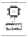
DISASSEMBLY INSTRUCTIONS
SCREW 3X10PA
SCREW 3X10PA
SCREW 3X10PA
3
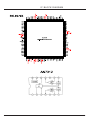
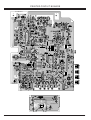
ADJUSTMENT LOCATIONS
4
ALIGNMENT PROCEDURES
CASSETTE SECTION
STEP
1
2
ITEM
NE-562MP3
DATE:12-ARP-2004
TEST EQUIPMENT
TEST TAPE
ADJUST
REMARK
MOTOR SPEED
WOW/FLUTTER METER
MTT-111N
(1)CHECK MOTOR
ADJ. &
WITH FREQ. COUNTER
(3KHz)
WOW/FLUTTER
CONNECT TO SPEAKER
CHECK
OR DUMMY LOAD
HEAD AZIMUTH
AC VOLT METER
MTT-113N
ADJUST THE R/P HEAD
TAPE
OSCILLOSCOPE
(6.3KHz)
SCREW FOR MAX
POSITION
SPEED TO 3KHz +3%-2% TAPE
POSITION
CONNECT TO SPEAKER
OUTPUT
OR DUMMY LOAD
3
4
PLAYBACK
CHECK FREQ
TAPE
FREQ
RESPONSE TO MEET
POSITION
RESPONSE
SPECIFICATION
RECORDING
SAME AS ABOVE
MTT-257
AC VOLT METER
BLANK
RECORED &
TAPE
OCILLOSCOPE
TAPE
PLAYBACK FORM FM
POSITION
CONNECT TO SPEAKER
SIGNA TO MEET
OR DUMMY LOAD
SPECIFICATIONS: REC
FM SIGNAL GEN
LEVEL, DISTORTION &
CONNECT TO ANT.
FREQ. RESPONSE
INPUT 1mV,40KHz DEV.
5
ALIGNMENT PROCEDURES
CASSETTE SECTION
STEP
1
2
ITEM
NE-562MP3
DATE:28-JUL-2004
TEST EQUIPMENT
TEST TAPE
ADJUST
REMARK
MOTOR SPEED
WOW/FLUTTER METER
MTT-111N
(1)CHECK MOTOR
ADJ. &
WITH FREQ. COUNTER
(3KHz)
WOW/FLUTTER
CONNECT TO SPEAKER
CHECK
OR DUMMY LOAD
HEAD AZIMUTH
AC VOLT METER
MTT-113N
ADJUST THE R/P HEAD
TAPE
OSCILLOSCOPE
(6.3KHz)
SCREW FOR MAX
POSITION
SPEED TO 3KHz +3%-2% TAPE
POSITION
CONNECT TO SPEAKER
OUTPUT
OR DUMMY LOAD
3
4
PLAYBACK
CHECK FREQ
TAPE
FREQ
RESPONSE TO MEET
POSITION
RESPONSE
SPECIFICATION
RECORDING
SAME AS ABOVE
MTT-257
AC VOLT METER
BLANK
RECORED &
TAPE
OCILLOSCOPE
TAPE
PLAYBACK FORM FM
POSITION
CONNECT TO SPEAKER
SIGNA TO MEET
OR DUMMY LOAD
SPECIFICATIONS: REC
FM SIGNAL GEN
LEVEL, DISTORTION &
CONNECT TO ANT.
FREQ. RESPONSE
INPUT 1mV,40KHz DEV.
6
5
ALIGNMENT PROCEDURES
MODEL:HIF-6880USMPT
FM AND AM RF ALIGNMENT CHART ( IF )
Step
item
Date:
Input Circuit
Output Circuit
Tuner
Adj -
Setup
Setup
setting
Point
Adjustment
Unless otherwise specified set switches as follows:
FM
Function: FM
Adjust generator frequency to a center of the FM band where no FM broadcast exists
IF
1
2
Adjustment
Connect FM IF
Connect Co19 and GND
sweep output
IF-OUT terminal to
terminal to IC302
IF sweep input terminal
FM
Band setup
3
Tracking (1)
FM in band
end
87.5 MHz
speaker terminal
108MHz
Headphone jack or
Terminal 90.1 MHz,
speaker terminal
T304
symmetrical S-curve
with max.amplitude.
Headphone jack or
FM SG ANT.
Adjust for straight and
90.1 MHZ
L303
Adjust L301 for max output
Done
L302
MONO
Adjust for max.output and
best waveform
1kHz, +-22.5kHz dev
4
5
Tracking (2)
106.1 MHz, 1 kHz
Headphone jack or
+-22.5 MHz dev
speaker terminal
106.1 MHz
CT303 Same as above.
IF
Connect standard loop
Connect input terminal
MW in band
Adjustment
antenna to output ter-
genescope to detector
end
T302
with symmetrical 450 kHz.
minal of genescope
output
T301
Adjust L135 for max output
Repeat steps 3 and 4.
MW
1
2
MW
Headphone jack or
522 kHz
Band
speaker terminal
1620 kHz
612 kHz 400 kHz,
Headphone jack or
612 kHz
T303
3% mod
speaker terminal
1404 kHz 400 kHz,
Headphone jack or
1404 kHz
CT301
3% mod
speaker terminal
3
Tracking (1)
4
Tracking (2)
5
Adjust tor max. amplitude
CT302 Adjust CT133 for max output
Adjust for max.output and
best waveform
Same as above.
Repeat steps 3 and 4.
TAPE SECTION
HEAD ADJUSTMENT (AZIMUTH)
10 kHz test tape (example:MTT-114N) must be used for this adjustment. Connect to VTVM or oscilloscope to the headphone JCK or speaker terminal Press the play button.
Adjust the azimuth by using a screw driver to maintain the maximum L & R output voltage. Adjust tape. Please secure the
azimuth position by using locking paint.
RECODING BIAS OSCILLATOR FREQUENCY ADJUSTMENT
Connect the frequency counter to of R601 two ends.
Press REC button of tape .
Adjust T201 obtain 60 kHz +-100 HZ
76
ALIGNMENT PROCEDURES
FM RECEIVER PERFORMANCE DATA
MODEL: NE-563PLL+MP3 (5W)
Band:
FM
Supply Voltage:
AC 230 V
Standard Output:
50
mw
Dummy Load:
4
ohm
Modulation:
1 KHz 22.5 KHZ DEV
EQ or Tone at Flat Place Bass OFF Place
Measuring Items
Unite
Frequency Range
Low
MHz
High
MHz
IF Frequency
MHz
30db Quieting
90.1
MHz
db
Sensitivity
98.1
MHz
db
106.1
MHz
db
Auto Locked
90.1
MHz
db
Sensitivity
98.1
MHz
db
106.1
MHz
db
ACA
+300
KHz
db
( 2-Signal )
-300
KHz
db
Image Rejection
AT 106.1 MHz
db
IF Rejection
AT 90.1 MHz
db
-3db Limiting Sens .
1mv I/P
db
AM Suppression
1mv I/P
db
S/N (1mv input
Mono
db
W/A-Fliter)
Stereo
db
Stereo Sens
db
Stereo Lamp On Sens.
db
Separation R/L
db
Freq.Response-3db
Low
Hz
(W/50uS Pre-emphasis)
High
KHz
Modulation Hum
1 mv I/P
db
Hum & Noise(min.vol.)
mv
Output (10% Dist) (MOD=40KHz)
mW
Total Harmonic Distortion
1 mv I/P
%
OSC Drop Out
1 mv I/P
V
Current
No signal
mA
Consumption
Max
mA
Date:
Measured By:
Approved By:
Norm
87.5
108
10.7
18
18
18
26
26
26
20
20
22
50
18
35
50
35
20
20
25
80
10
40
1
4500
1
Limit
+/-0.3
+/-0.3
+/-0.2
26
26
26
32
32
32
15
15
16
40
26
30
45
30
26
26
20
≦100
≧8
35
3
4000
3
Sample1
Sample2
87
ALIGNMENT PROCEDURES
MW RECEIVER PERFORMANCE DATA
MODEL: NE-563PLL+MP3 (5W)
Band:
MW
Supply Voltage:
AC 230 V
Standard Output:
50
mw
Dummy Load:
4
Ohm
Modulation:
1 KHz 30%
EQ or Tone at Flat Place Bass OFF Place
Measuring Items
Unite
Norm
Frequency Range
Low
KHz
522
High
KHz
1620
IF Frequency
KHz
450
20db Quieting
612
KHz dB/M
60
Sensitivity
999
KHz dB/M
60
1404
KHz dB/M
60
Auto Locked
612
KHz dB/M
66
Sensitivity
999
KHz dB/M
66
1404
KHz dB/M
66
S/N 5mv/M
dB
35
ACA
+9
KHz
dB
18
-9
KHz
dB
18
Band Width-6dB
+Side
KHz
3
-Side
KHz
3
Image Rejection
AT 1404 KHz
dB
35
IF Rejection
AT 612 KHz
dB
50
Spuerious Response
4-10MHz
dB
40
10-30MHz
dB
50
AGC FOM-10db
100mv/M
dB
45
Audio Freq.
Low
Hz
80
Response-6db
High
KHz
2.4
Modulation Hum
100 mv/M
dB
38
Hum (Volume At Min)
mv
1
Output (10% Dist) (MOD=80%)
mW
4500
Total Harmonic Distortion
5mv/M
%
2
OSC Drop Out
5mv/M
V
Current
No signal
mA
Consumption
Max
mA
Date:
Measured By:
Approved By:
Limit
+/-10
+/-10
+/-2
66
66
66
70
70
70
30
12
12
10
10
30
40
35
45
35
≦100
≧2.0
32
3
4000
4
Sample1
Sample2
98
ALIGNMENT PROCEDURES
CASSETTE PLAYBACK PERFORMANCE DATA
MODEL: NE-563 PLL&MP3 (5W)
Supply Voltage:
AC 230 V
Standard Output:
50
mw
Measured By:
Dummy Load:
4
Ohm
0DB=1V
Approved By:
EQ or Tone at Flat Place Bass OFF Place
Tape Speed 4.76cm/sec.1 7/8 I n
Measuring Items
Tape Speed Enor
at
3
KHz
WOW & Flutter
at
3
KHz
Play Freq Response
at
Hz
at
125
Hz
at
1
KHz
at
10
KHz
at
KHz
P/B S/N (1K odB)
DC Opetation
AC Optetaion
Min Vol Hum & Noise
AC Optetaion
Max Vol Hum & Noise
AC Optetaion
10% THD Output
(1KHz odB) RMS
THD
at
Hz
-10dB 1KHz
at
1
KHz
at
KHz
Track Crosstalk
Channel Separation
R-L
L-R
Channel Balance -10dB 1KHz
No Signal Current Min. Vol. Blank Tape
Max Output
Max. Vol
Play Torque
F.F Torque
Rew Torque
Time for Play
Time for F.F
Time for Rew
Play Level
Tape = 0dB Ref
CD Play
1KHz-10dB
Radio
FM 1KHz 40KHz
Unite
%
%
dB
dB
dB
dB
dB
dB
dB
mv
mv
mw
%
%
%
dB
dB
dB
dB
mA
A
g/cm
g/cm
g/cm
Min
Sec
Sec
dB
dB
dB
Norm
0.25
Limit
+3/-2
0.35
+/-3
0
+/-3
+/-6
0
+/-6
45
1
20
4500
40
3
30
4000
1
3
40
40
40
1
30
30
30
3
0
-2
+/-1
0
-4
+/-3
Date:
Sample1
Sample2
10
9
ALIGNMENT PROCEDURES
CASSETTER REC/PLAY PERFORMANCE DATA
MODEL: NE-563 PLL&MP3 (5W)
Supply Voltage:
AC 230 V
Standard Output:
50
mw
Measured By:
Dummy Load:
4
Ohm
0DB=1V
Approved By:
EQ or Tone at Flat Place Bass OFF Place
Date:
Tape Speed 4.76cm/sec.1 7/8 I n
Measuring Items
Rec Blas System
AC
Erasing System Magnet
Erasing Ratio
ALC Compresion Time
for 20db
Stansatding up for -20db at 90%
Recovery time for -20db at 90%
R/P Frep Response
at
100
Hz
REC CD(-20dB)
at
1
KHz
at
10 KHz
R/P S/N
Built Mic
FM 1mv/in
R/P THD
at -10dB 1KHz
R/P Channal Separation
L-R
(1KHB 0dB)
R-L
Record Level Tape = -10dB
CD
1KHz -20dB
Radio
FM 1KHz 12.5KHz
Remote Control Sensitivity
Headphone Out Level (32 ohm)
Bass Tone Action
at
Hz
Prest EQ REF O/P 0dB PASS
100 Hz
CLASSIC
1K Hz
10K Hz
100 Hz
ROCK
1K Hz
10K Hz
100 Hz
POP
1K Hz
10K Hz
100 Hz
JAZZ
1K Hz
10K Hz
Unite
KH z
dB
dB
Sec
Sec
dB
dB
dB
dB
dB
%
dB
dB
dB
dB
dB
m
mW
dB
dB
dB
dB
dB
dB
dB
dB
dB
dB
dB
dB
dB
Norm
55
6PA
38
Limit
60
+/-3
0
+/-3
+/-6
+/-3
+/-6
38
5
40
40
0
+/-2
+/-2
7
20
33
10
30
30
0
+/-4
+/-4
5
15
+4
+3
+8
+8
+3
+6
-4
-2
-4
+6
+2
+4
+/-2
+/-2
+/-2
+/-2
+/-2
+/-2
+/-2
+/-2
+/-2
+/-2
+/-2
+/-2
Sample1
Sample2
33
10
11
ALIGNMENT PROCEDURES
NELSON ELECTRONICS LTD
CD PLAYBACK PERFORMANCE DATA
MODEL: NE-563 PLL+MP3 (5W)
Supply Voltage:
AC 230 V
Standard Output:
50
mw
Dummy Load:
4
Ohm
0dB=1V
EQ or Tone at Flat Place Bass OFF Place
Measuring Items
Unite
Norm
WOW & Flutter
%
Play Freq Response
at
40
Hz
dB
-2
(0dB)
at
61
Hz
dB
-1
at
127
Hz
dB
0
at
1
KHz
dB
0
at
10 KHz
dB
0
at
20 KHz
dB
-3
P/B S/N (YEDS)
DC Opetation
dB
AC Optetaion
dB
55
Hum & Noise
Min Vol
mv
2
( AC Optetaion)
Max Vol
mv
5
10% THD Output
RMS
mw
4500
THD (-20dB)
at
1
KHz
%
1
Channel Separation
R-L
dB
40
YEDS (0dB)
L-R
dB
40
Channel Balance (1KHz -10dB)
dB
1
Black Spot
PHILIPS-444A
UM
800
Finger Prints
PHILIPS-444A
TRACK
19
Interruption
PHILIPS-444A
UM
800
Deflection
731RA
MM
1
Eccentricity
712R
UM
210
Access Operation
First
Sec
Time
Last
Sec
MP3 PLAYBACK PERFORMANCE DATA
MP3 Playback Transfer Rate
MP3 Max Readable Folder
MP3 Max Readable Files
MP3 Sampling Frequency
kbps
Folde
File
KHz
Date:
Measured By:
Approved By:
Limit
Sample1
Sample2
+/-3
+/- 2
+/-2
0
+/-2
-5
50
3
8
4000
3
30
30
3
600
18
600
0.9
140
8~384
200
500
32/44.1/48; 16/22.05/24; 8/11.025/12.
11
12
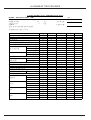
VOLTAGE CHARTS
IC VOLTAGE TABLE
{DC12V,NO SIGNAL INPUT (EXCEPT FM STEREO BAND),VOLUME MINMUN}
AC 230V 50HZ
LA1823 &LC72131 & AN7312 & PT2313L
MODEL : NE-562MP3 5W
TA8229K & PT2221 & S3C825AX27
TUNER LA1823+LC72131
S1l9226X01 & KA9259D & S5L9279X01 & JF1M16SDT-7
PINS
AM
FM
FM.ST
IC302
LA1823
IC301
LC72131
IC201
AN7312
IC602
PT2313L
VOLUM
EQ
FUN
PINS
AM
FM
FM.ST
PINS
AM
FM
FM.ST
1
2
3
4
5
6
7
8
9
10
4.5
1.29 1.28 0.35
11
12
13
15
16
0
0.02 3.38
1.29 1.29 4.43 4.43 2.16
0
0.02 3.38 4.42 1.29 1.28
0.3
3.67 3.74
3.7
0.73
1.29 1.29 4.43 4.43 2.16
0
0.02 3.38 4.42 1.29 1.28
0.3
3.67 3.74
3.7
0.73
15
16
17
18
19
20
21
22
23
0
0
0.74 1.25 1.39 4.47 4.46 4.39
0
0.91
0.74 1.25 1.39 4.47 4.36 4.39
0
0.91
7
8
2
3
4
5
6
0.03 0.15 0.74
24
0.74 1.25 0.32 4.61 4.61 4.61
1
4
14
1.27 1.27 4.61 4.61 2.62
9
10
11
12
13
14
2.25
0
0
3
3
3.64 3.78 3.78
0
0.02 4.45
0.3
0
0
0
0.22
2.19
0
0
0.2
3
3.64
0.02
0
0.02 4.45
0
0
0
0.3
2.18
2.2
0
0
0.2
3
3.64 3.79 3.79
0
0.02 4.45
0
0
0
0.2
2.18
PINS
AM
FM
FM.ST
17
18
19
20
21
22
4.5
0.82 0.82
3.1
0
2.3
4.5
0.82 0.82
3.1
0
2.3
4.5
0.82 0.82
3.1
0
2.3
PINS
TAPE
1
2
3
4
5
6
7
8
9
10
11
12
13
14
0
1
0
3
1.4
1.3
0
0
1.3
1.4
3
0
6
6
PINS
RADIO
CD
TAPE
1
2
3
4
5
6
7
8
9
10
11
12
13
14
15
16
6.34
0
3.18 3.18 3.19
3.2
3.19 3.18 3.18 3.18 3.18 3.19 3.18 3.18 3.18 3.18
6.34
0
3.18 3.18 3.19
3.2
3.19 3.18 3.18 3.18 3.18 3.19 3.18 3.18 3.18 3.18
6.34
0
3.18 3.18 3.19
3.2
3.19 3.18 3.18 3.18 3.18 3.19 3.18 3.18 3.18 3.18
17
18
19
21
22
23
24
25
3.19
3.2
3.18 3.19 3.18
3.2
3.2
3.2
0
0.22 3.05 3.19
3.19
3.2
3.18 3.19 3.18
3.2
3.2
3.2
0
0.22 3.05 3.19
3.19
3.2
3.18 3.19 3.18
3.2
3.2
3.2
0
0.22 3.05 3.19
PINS
RADIO
CD
TAPE
IC601
PINS
TA8229K POWER
20
3.9
26
27
28
1
2
3
4
5
6
7
8
9
10
11
12
13
14
15
0
16.8
9
17.5
9.1
17
0
17.2
9.1
0.5
0
0
0.6
0
0
13
12
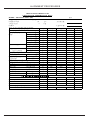
VOLTAGE CHARTS
PINS
DRAM
U7
SDRAM
16M
3
3.41 2.52 2.42
4
5
0
2.2
6
7
8
9
10
11
12
13
14
2.21 3.41
2.2
2.2
0
2.19
2.2
3.41
0
30
17
18
19
20
21
22
23
24
25
26
27
28
29
DRAM
3.41
0
0
3.41
0
0
0
0
3.41
0
0
0
0
33
34
35
36
37
38
39
40
41
42
43
44
45
PINS
0.11 1.69 3.41
PINS
49
50
DRAM
2.45
0
PINS
RADIO
CD
TAPE
AUX
PINS
RADIO
CD
TAPE
AUX
0
3.41 2.44 2.45
0
2.41 2.45 3.41 2.43 2.44
15
16
3.41 3.41
31
0.21 3.41
32
0
46
47
48
0
2.43
2.45
14
15
16
1
2
3
4
5
6
7
8
9
10
11
12
13
1.41
0
0
0
0
0
0
0
0
0
0
2.88
0
1.39 1.32
0
1.41
0
0
0
0
0
0
0
0
0
0
2.88
0
1.39 1.32
0
1.41
0
0
0
0
0
0
0
0
0
0
2.88
0
1.39 1.32
0
1.41
0
0
0
0
0
0
0
0
0
0
2.88
0
1.39 1.32
0
17
18
19
20
21
22
23
24
25
26
27
28
29
31
32
0
0
0.86
0.3
0.08
0
2.92 1.39 2.92 2.92 2.92
0
1.05
1.08 1.36 2.87
30
1
1.36 2.87
0
0
2.87 2.87 2.87
0
2.92 1.39 2.92 2.92 2.92
0
1.05
1
1.36 2.87
0
0
2.87
0.3
0.25
0
2.92 1.39 2.92 2.92 2.92
0
1.05
1
1.36 2.87
0
0
2.87
0.3
0.25
0
2.92 1.39 2.92 2.92 2.92
0
1.05
37
38
39
48
PINS
RADIO
CD
TAPE
AUX
33
34
35
36
40
41
42
43
0
0
0
0
2.86 1.81 2.86
0
0
0
0
0
2.88
0
0
2.86 1.81 2.86
0
0
2.79
0
0
0
0
0
2.86 1.81 2.86
0
0
0
0
0
0
0
2.86 1.81 2.86
0
0
0
PINS
RADIO
CD
TAPE
AUX
49
50
51
52
56
57
58
59
0
0
2.88
0
2.88 1.42 1.42 1.42 1.42 1.42 1.42 1.42 1.42 1.42 1.42 1.42
2.91
0
2.88
0
2.88 1.42 1.42 1.42 1.42 1.42 1.42 1.42 1.42 1.42 1.42 1.42
2.91
0
2.88
0
2.88 1.42 1.42 1.42 1.42 1.42 1.42 1.42 1.42 1.42 1.42 1.42
2.91
0
2.88
0
2.88 1.42 1.42 1.42 1.42 1.42 1.42 1.42 1.42 1.42 1.42 1.42
65
66
67
68
PINS
RADIO
CD
TAPE
AUX
U5
KA9259D
2
PINS
DRAM
U2
S3C825A
1
53
69
54
70
55
71
72
73
74
45
46
47
2.73 2.73
3.4
3.54 2.91
0.06
0.3
2.91
0
2.73 2.73 0.03
0.7
2.91
0
2.73 2.79 0.03
0.7
2.91
60
63
64
75
44
0
76
0
61
77
62
78
79
80
1.42 1.42 1.42 1.42 1.42 1.42 1.42 1.42 1.42 1.42 1.42 1.42 1.42 1.42 1.42 1.42
1.42 1.42 1.42 1.42 1.42 1.42 1.42 1.42 1.42 1.42 1.42 1.42 1.42 1.42 1.42 1.42
1.42 1.42 1.42 1.42 1.42 1.42 1.42 1.42 1.42 1.42 1.42 1.42 1.42 1.42 1.42 1.42
1.42 1.42 1.42 1.42 1.42 1.42 1.42 1.42 1.42 1.42 1.42 1.42 1.42 1.42 1.42 1.42
PINS
1
2
MOTOR
3.7
3.7
1.69 1.69 7.38 4.99 4.99
3
4
PINS
17
18
19
20
MOTOR 3.72 3.72 1.69 4.32
5
6
21
22
8
0
7
23
8
0
24
10
11
12
13
14
1.69 1.69
9
3.7
3.72
0
0
25
27
28
26
1.69 1.69 1.69 3.72 3.72
15
16
3.72 3.72
0
14
13
VOLTAGE CHARTS
MODEL NE -562
U3
S5L9279
U1
S1L9226
PINS
DSP
1
2
3
4
5
6
7
8
9
10
1
2.07
0
0
0
2.07
0
0
1.7
1.69 3.38 3.38 1.69
PINS
DSP
17
18
19
20
21
22
23
24
25
26
27
28
0
0
0
0
0
3.38
0
0
0
38
39
40
41
42
43
0
2.07
0
59
3.38 1.66
11
12
13
14
15
16
0
0
0
29
30
31
32
0
0
3.38
0
0
44
45
46
47
48
PINS
DSP
33
34
35
36
37
0
0
3.38
0
0
PINS
DSP
49
50
51
52
53
54
55
56
57
58
0
0
2.4
2.82 2.62
2.7
0.77 0.73 0.36 2.76 2.07
68
69
70
71
72
73
74
0
3.38
0
0
89
2.46 2.48 2.09
62
63
64
0
1.13
81
82
83
84
85
86
87
88
0
0
1.61
1.7
2.07
0
2.88
0
PINS
DSP
97
98
PINS
SSP
1
5
6
7
8
1.71 1.75 1.69 1.52
1.7
3.38
1.7
0.82 1.69 1.68 1.72 1.63 3.38 2.79 2.82 2.87
17
20
21
22
23
24
0
0
0
36
37
38
PINS
SSP
18
3
19
2.87 0.07 1.69
90
2.75 1.63
78
79
80
0
0
0
0
91
92
93
94
95
96
0
0.06
0
0
0
0
11
12
13
14
15
16
35
0
4
9
25
10
26
27
28
29
33
IC602
KA7808
PINS
1
2
3
RE901
PINS 1
2
3
14
0
8
RECEIVEER
4.4
0
4.4
Q607
8050
PINS
Q304
9014C
PINS E
Q620
8050
PINS
Q303
8050C
1.71 1.66 1.66 3.37
E
B
C
5.8
4.3
12.9
E
B
C
6.2
6.8
10
0
30
31
32
1.71 1.71 1.71 1.71 1.71 1.71 1.71 1.71 1.71 1.71
PINS
SSP
0
34
3.38 3.38 1.69
77
99 100
0.07 1.69
2
76
61
PINS
DSP
2.76 1.72 3.38 3.38
75
60
65
0
67
2.45 2.46 2.51 2.46 2.48
PINS
DSP
0
66
3.31 3.37 3.38
39
40
41
42
43
44
45
46
47
1.71 1.71 1.71 1.71 1.69 1.22 0.89
2.5
1.71 2.45
B
C
11
16.8
PINS E
B
C
4.5
5.2
7.6
10.3
48
REMARK : ALL THE DATA IN THE TABLE IS FOR.REFERENCE ONLY
FOR FM.ST BAND , FM STEREO INDICATOR MUST BE ON.
15
MODEL NE -562
IC BLOCK DIAGRAM
16
MODEL NE -562
IC BLOCK DIAGRAM
17
MODEL NE -562
IC BLOCK DIAGRAM
18
MODEL NE -562
IC BLOCK DIAGRAM
19
MODEL NE -562
IC BLOCK DIAGRAM
20
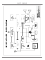
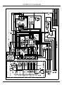
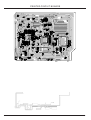
BLOCK DIAGRAM
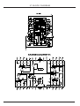
21
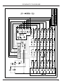
WIRING DIAGRAM
22
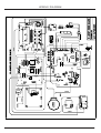
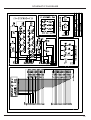
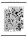
SCHEMATIC DIAGRAMS
23
22
SCHEMATIC DIAGRAMS
23
24
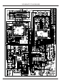
SCHEMATIC DIAGRAMS
25
24
SCHEMATIC DIAGRAMS
25
26
SCHEMATIC DIAGRAMS
26
27
SCHEMATIC DIAGRAMS
27
28
SCHEMATIC DIAGRAMS
29
28
SCHEMATIC DIAGRAMS
30
28
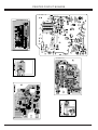
PRINTED CIRCUIT BOARDS
173-056320-01
173-056301-09
31
PRINTED CIRCUIT BOARDS
173-056320-01
32
PRINTED CIRCUIT BOARDS
33
PRINTED CIRCUIT BOARDS
173-056351-01
173-0563�1-09
173-056356-01
34
MODEL NE -562
EXPLODED VIEW/PARTS LIST (CABINET)
35
EXPLODED VIEW/PARTS LIST (CABINET)
56
57
36
MODEL NE -562
EXPLODED VIEW/PARTS LIST (CABINET)
O.
ITEM
1
2
3
4
5
6
7
8
9
10
11
12
13
14
15
16
17
18
19
20
21
22
23
24
25
26
27
28
29
30
31
32
33
34
35
36
37
38
39
40
41
42
43
44
45
46
47
48
49
50
51
52
53
PART NO.
357-056220-6500
358-056210-6500
333-056200-8890
425-059501-1C20
425-059500-1C20
177-023502-03
311-056281-6500
303-000090-0201
420-056210-3890
188-011522-01
408-0562-141860
472-056211-1000
412-056212-2500
148-250001-101
403-056214-2500
133-6038LM-5A10
199-000002-01
408-056217-2490
148-030000-40
134-056220-051
461-056222-1100
461-056222-1100
461-05920-1010
303-000082-0001
218-057512-32
400-056211-2490
464-056206-1000
420-056210-3890
463-05620V-1000
188-011532-02
057520-53J0
381-057510-53J0
262-001510-10
156-582313-03
211-003115-15
199-000060-02
322-059561-53J0
177-070000-011
461-05923G-1010
460-056202-1000
460-056201-1000
460-056200-1000
461-05622M-1000
143-450220-03
213-000005-16
219-DA11BV-ZS
303-000072-1301
202-082201-01
238-056200-01
183-100060-02
374-059240-53J0
371-059221-6501
375-059200-8KT0
DESCRIPTION
CASSETTE KNOB COVER
CASSETTE DOOR
FRONT LENS
CASSETTE KNOB – PLAY
CASSETTE KNOB
STEREO JACK
FRONT CABINET
MOUNTING POST REV.
VOLUME BUTTON RING
TACT SWITCH
FUNCTION BUTTON
FUNCTION KNOB BASE
MUTE BUTTON
LED
POWER/STANDBY BUTTON
IR RECEIVER
OIL DAMPER
CD OPEN BUTTON
LED
LCD
LCD REFLECTOR
LCD BRACKET
CASSETTE DOOR BRACKET
CASSETTE KNOB FIXER
DECK THL-21SB-1592P
VOLUME KNOB
VOLUME KNOB SHAFT
VOLUME KNOB RING
VOLUME KNOB ADAPTOR
TACT SWITCH
BATTERY DOOR
BATTERY BOX
RUBBER FOOT
X’FORMER
BELT MOTOR DIA
MOTOR PULLY
REAR CABINET
SPEAKER TERMINAL
GEAR BRACKET
CD DOOR GEAR
ADAPTOR GEAR
MOTOR GEAR
MOTOR BRACKET
MOTOR
CUSHION RUBBER
CD MECHANISM
DUST COVER
HEAT-SINK
CASS KNOB COVER
FERRITE BAR
CD BRACKET
CD DOOR
CD DOOR LENS
QTY
1
1
1
1
5
1
1
6
1
11
8
1
1
1
1
1
1
1
3
1
1
1
1
1
1
1
1
1
1
2
1
1
8
1
1
1
1
1
1
1
1
1
1
1
4
1
1
1
1
1
1
1
1
ITEM
54
55
56
57
58
PART NO.
238-056200-11
188-000402-00
461-000050-01
461-000051-01
188-012721-01
DESCRIPTION
CASS DOOR DECORATION
LEAF SWITCH
Cd pcb mounting bracket
Cd pcb mounting bracket
AC POWER SWITCH
QTY
1
1
1
1
1
P1
P2
P3
P4
P5
P6
P7
P8
P9
P10
173-059205-01
173-056303-01
173-056302-0102
173-056301-09
173-056220-0102
173-056656-0101
173-056651-0102
173-056209-01
173-056304-01
173-056205-0101
HEARPHONE JACK BOARD
FUNCTION KEY BOARD
USB SOCKET BOARD
MEMORY CARD BOARD
A/F+R/P+5W BOARD
R/P BOARD
MCU+CD SERVO BOARD
BACK LIGHT BOARD
VOLUME BOARD
VOLUME LIGHT BOARD
1
1
1
1
1
1
1
1
1
1
S1
S2
S3
S4
203-300200-10
203-300200-12
203-350800-14
207-261600-10
SCREW 3X10 PA
SCREW 3X12 PA
SCREW 3.5X14 PWA
SCREW 2.6X10PWB-10W
44
7
4
4
37