1
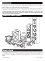
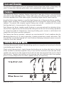
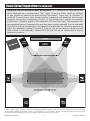
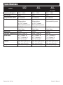
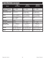
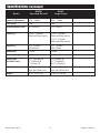
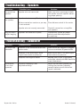
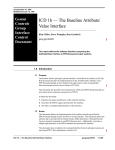
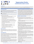
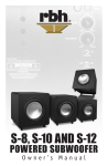
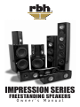
IMPRESSION SERIES
FREESTANDING SPEAKERS
Owner ’s Manual
Introduction
Congratulations on your purchase of Impression Series freestanding speakers! Your speakers
are the result of many years of research and development dedicated to producing high
quality products for home audio and audio/video systems.
This manual contains features, setup recommendations and specifications for the Impression Series freestanding speakers. It is recommended you thoroughly read through the
material contained in this manual before connecting your speakers. This will ensure you
have a good understanding of how to setup your speakers for optimum performance and
allow for years of listening enjoyment.
Impression Series Speakers
R55Ti
R5Ti
RS1010i
RS10i
R55Wi
R5Bi
R5Ci
R56Ci
Break-in Period
Allow several hours of listening time to adequately break-in the Impression Series speakers.
As the speakers break-in, the driver suspensions will loosen. The result of break-in will
be an increase in low frequency response, improved definition, and increased clarity and
detail.
Impression Series
1
Owner’s Manual
Care and Cleaning
To maintain speaker appearance, we recommend wiping them down with a clean damp soft
cloth. To clean dust from the grille cloth, use a vacuum with a brush attachment.
Features
The Impression Series speakers feature poly-matrix cone bass drivers and aluminized
poly-matrix cone midrange drivers. These rigid cones resist flexing and contribute to the
accurate reproduction of the audio signal, providing higher overall sound quality.
A quality fabric dome tweeter is used for high frequencies in Impression Series speakers.
Higher power handling is achieved through the use of magnetic liquid cooling in the
tweeter. To protect the tweeter against being over driven, a polyswitch (a current
limiting device) is incorporated in the crossover network.
Each Impression Series speaker model features a crossover network to minimize driver
interaction irregularities and maximize the ability of each driver to accurately reproduce
its respective band of frequencies. Five-way binding posts ensure a solid electrical
connection to these crossover networks.
The Impression Series speakers’ cabinets are constructed of ½-inch medium density
fiberboard because of its inert properties, thereby minimizing sound coloration. The
front baffles are double layered to 1-inch thickness helping to prevent excess acoustic
radiation from the cabinet.
Attaching Speaker Wires
If using a banana jack, attach the matching positive or negative wire and push directly
into binding post top hole.
If not using a banana jack, simply loosen the binding nut to allow the hole in the side
of the terminal to become exposed. Strip ¼-inch of the insulation from the end of the
speaker wire and insert the exposed wire end into the now exposed hole in the side of
the terminal. Tighten the binding nut by turning the nut clockwise until the speaker
wire is secured. Repeat for the other speaker wire(s) as necessary.
Impression Series
2
Owner’s Manual
Room Setup Suggestions
In order to obtain the best possible sound from your speaker system, it is important to
determine where the speakers will sound best in your listening room. Room reflections
from the floor, ceiling and side walls influence the balance, imaging and overall sonic
quality at the listening position. Experiment with speaker placement to determine which
location offers the best overall sound. As a general guide, use the room layout diagram
and the following descriptions when setting up a home theater system. Some speakers
shown in the diagram may not always be applicable to your system.
Front Main Speakers
As a starting point, place your left and right tower speakers at least 15 inches from the
wall and 7-feet apart from each other. The distance from the listening position to each
speaker should be close to the distance that separates the two main speakers. Angling
the speakers inward towards the listening position may give a more spacious and realistic
sound stage.
Center Channel Speaker
The center channel speaker should be placed in the center between both left and right
main speakers. Often this positioning dictates placing the speaker either directly above
or below a television monitor.
Rear Surround Speakers
The 2-way bookshelf speakers may be placed either above, behind or to the sides of
the listening position. The listening position should be centered between the surround
speakers. For best performance you may want to experiment with angling the surround
speakers either towards or away from the listening position. If using R55Wi surround
speakers, the optimal location for these is about 5-6 feet high on the walls to the left
and right of the listening position. This position should allow one half of the speaker to
point forward of the listening position, while the other half of the speaker points behind
the listening position.
Subwoofer
In order to obtain the best possible sound from your subwoofer, it is important to determine
where the subwoofer will sound best in your listening room. Sound reflections from the
floor, ceiling and side walls influence the balance, imaging and overall sonic quality at
the listening position. Experiment with subwoofer placement to determine which location
offers the best overall sound.
Placement of the subwoofer will largely determine quality, quantity and extension of the
bass frequencies within your listening room. Bass frequencies are reinforced by close room
boundaries. Placing the subwoofer close to a corner will make the subwoofer sound louder
and boost the very lowest frequencies.
Placing the subwoofer away from walls will provide the least reinforcement, making the
bass sound subjectively thinner than if the woofer were closer to a wall. Good results can
usually be obtained by placing a subwoofer along a wall 1-3 feet from a corner. Experiment
with placement of the subwoofer and the sub-amplifier controls to achieve the proper
bass balance.
Impression Series
3
Owner’s Manual
Room Setup Suggestions (continued)
IMPORTANT NOTICE REGARDING BASS MANAGEMENT: It is important the signal being sent
to the subwoofer be a non-boosted or “flat” signal. To be sure of this, check the settings
on your receiver or processor to make sure any “bass boost”, “super bass” or “loudness” is
set to Off. In most cases a home theater receiver or processor will determine the crossover
frequency through bass management settings. In this configuration, connect the receiver’s
or processor’s subwoofer output to the subwoofer’s LFE Line Level Input. Your subwoofer will
now reproduce the bass frequencies the way they were originally recorded. Use the subwoofer
level control and the individual bass management control within the receiver or processor to
adjust the subwoofers’ volume if necessary. Once set, the volume controls should not need
to be altered as the subwoofers’ volume will track with the master volume control of your
receiver or processor.
NOTE: There are several different surround formats available. Dolby Pro-Logic, Pro-Logic II, Dolby Digital and DTS generally
have a 5 speaker plus subwoofer requirement. Dolby Digital EX and DTS ES add a center rear speaker. Dolby TrueHD and DTS
Master Audio available only on Blu-ray disc, generally have a 7.1 requirement. Please consult your audio/video professional
to determine which system is best for you and how many speakers you will require.
Impression Series
4
Owner’s Manual
Subwoofer Safety Instructions
The lightning flash with the arrowhead symbol within an equilateral triangle, is intended
to alert the user to the presence of un-insulated “dangerous voltage” within the product
enclosure that may be of sufficient magnitude to constitute a risk of shock to persons.
The exclamation point within an equilateral triangle is intended to alert the user to
the presence of important operating and maintenance (servicing) instructions in the
literature accompanying the product.
When using your subwoofer, basic safety precautions should always be followed to reduce
the risk of fire, electric shock, and injury.
1. Read and understand all instructions in this users manual before operating the
subwoofer and retain this user manual for future reference.
2. Follow all warnings and instructions in this manual and any marked on the back of
the Subwoofer.
3. Never touch the woofer or push objects of any kind into the woofer.
4. The subwoofer should be connected to a power supply compatible with the power
consumption requirements, see the specifications section of this manual.
5. If mounting the subwoofer on a stand, the wall, or other device only do so as
recommended by an authorized technician.
6. Place the subwoofer a safe distance from all heat sources such as radiators, stoves,
or heaters.
7. Do not operate the subwoofer near water—for example, near a bathtub, kitchen
sink or in a wet basement; or a swimming pool.
8. Power supply cords should be routed so they are not likely to be walked on or
pinched by items placed upon or against them.
9. Any service or repair required must be performed by qualified, authorized
technician.
Impression Series
5
Owner’s Manual
Subwoofer Amplifier Controls and Setup
This section describes the functions and/or use for each of the amplifier controls
located on the back of the subwoofer. See the diagram of the back of the subwoofer
on the next page.
1. Voltage Selector Switch: Before connecting the amplifier to any power source
make sure the AC Voltage Selector is set to either 110V or 220V to match the
power voltage in your area.
WARNING! If the voltage setting does not match the AC power supplied,
damage to the Subwoofer Amplifier may result.
2. Volume/Gain Control: The volume/level control should be at the minimum
setting (all the way counter-clockwise) before plugging the subwoofer into an
AC wall socket. Once plugged in, turn the level control up one quarter of a turn
(9 o’clock position) for an initial setting. The level control may be adjusted
while playing to match the subwoofer level with the rest of the system.
IMPORTANT! The volume control should be at the minimum setting (all the way
counter-clockwise) before plugging the subwoofer into an AC wall socket.
3. Crossover Frequency Control: The variable crossover frequency control allows
you to set the low-pass crossover point of the subwoofer anywhere from
40-150 Hz. Increasing the crossover frequency will allow more mid-bass output
from the subwoofer. Decreasing the frequency will allow only deeper bass from
the subwoofer. Experiment with setting the crossover frequency control at
highest setting initially.
NOTE: Read the Important Notice regarding bass management on page 4.
4. Auto Signal Tracking: The subwoofer amplifier uses “smart” signal tracking
circuitry. Once the power cord is plugged in and the switch set to auto, the amplifier
automatically turns on when a signal is detected at the Line or LFE inputs and turns
off when no signal has been detected for about 15 minutes.
5. Phase Control: This control changes the phase of the subwoofer. Changing
the phase will change the way the subwoofer and main speakers interact with
each other at the crossover frequency. Varying the phase position may result
in more or less mid bass depending on the phasing between the main speakers
and the subwoofer. Generally, the phase is left at the “0 degrees” position.
6. Line Inputs: Line level inputs are used to connect to most full-range stereo receivers
or processors, use both the L and R terminals.
7. LFE In: The Low Frequency Effect input is to connect to the “LFE” bass
management output of the receiver or processor and may also be called
“Subwoofer Output”.
Impression Series
6
Owner’s Manual
Subwoofer Amplifier Controls and Setup (continued)
8. LFE Out: This RCA terminal is for “daisy chaining” to another subwoofer.
9. Fuse Access: This is the power fuse access.
WARNING! In the event the fuse must be replaced, the replacement fuse must
match exactly the original fuse value. If the replacement fuse is not of the
same value, damage to the Subwoofer Amplifier may result.
CAUTION! Before replacing the fuse, disconnect the power cord from the power
receptacle.
10.Power: Power on and off switch.
2011 + Impression Series Subwoofer Diagram.
Impression Series
7
Owner’s Manual
Tower Speaker Outrigger Installation
Use these attractive, tower speaker outriggers for the Impression Series tower speakers
to create a wider support base for the cabinet. These outriggers make your tower speakers
more stable, and are ideal when placing them on a thickly carpeted floor.
Package contents include: 1 each small outriggers for back of cabinet
1 each large outriggers for front of cabinet
4 metal spike feet
4 metal rubber cone feet
4 each top cap nuts
4 each threaded adjustment washers
4 each machine screws
The metal spike feet work best on carpeted surfaces. The rubber cone feet have been included
for use with wooden or tiled floors.
Attach the tower speaker outrigger plates to
the bottom of the speaker with the machine
screws provided, as shown in figure 2 below. The larger plate should be at the front of the
speaker and the smaller plate at the back of the speaker.
NOTE: To prevent scratching or damaging of the cabinet, turn the tower upside down on
a soft surface when attaching the outrigger feet.
Attach the metal spike or rubber cone feet using the top cap nuts as shown in figure 1.
Adjust the level/height using the adjustment washer above the metal spike or rubber
cone feet.
Impression Series
8
Owner’s Manual
Specifications
R55Ti
Tower
Model
R5Ti
Tower
R5Ci
Center
Channel
Frequency Response:
40Hz – 20kHz
50Hz – 20kHz
60Hz – 20kHz
Sensitivity:
88dB
87dB
87dB
Recommended Power:
50-200 Watts
50-150 Watts
50-120 Watts
Woofer:
(3) 6½” (165mm)
Polypropylene
(2) 6½” (165mm)
Polypropylene
(2) 5¼” (133mm)
Aluminized Poly-matrix
(2) 5¼” (133mm)
Aluminized Poly-matrix
(1) 5¼” (133mm)
Aluminized Poly-matrix
Tweeter:
(1) 1” (25mm)
Fabric Dome
(1) 1” (25mm)
Fabric Dome
(1) 1” (25mm)
Fabric Dome
Impedance:
6 Ohms
6 Ohms
6 Ohms
Crossover Frequencies: 120Hz / 3000 Hz
120Hz / 3000 Hz
3000 Hz
Dimensions:
8 /2” (216mm) W
471/2” (1207mm) H
121/4” (311mm) D
8 /2” (216mm) W
351/2” (902mm) H
121/4” (311mm) D
213/4” (553mm) W
71/4” (184mm) H
73/4” (197mm) D
Cabinet:
High-gloss Red Burl or
High-gloss Black Ash
52 lbs. (23.59 Kg)
High-gloss Red Burl or
High-gloss Black Ash
35 lbs. (15.88 Kg)
High-gloss Red Burl or
High-gloss Black Ash
11.5 lbs. (5.22 Kg)
Weight:
Impression Series
1
1
9
Owner’s Manual
Specifications (continued)
R5Bi
Bookshelf
Model
RS10i
Subwoofer
RS1010i
Subwoofer
Frequency Response:
60Hz – 20kHz
35Hz – 180Hz
30Hz – 180Hz
Sensitivity:
85dB
N/A
N/A
Recommended Power:
50-100 Watts
250 Watts RMS
(Amplifier Power)
250 Watts RMS
(Amplifier Power)
Woofer:
(1) 5¼” (133mm)
Aluminized Poly-matrix
(1) 10” (254mm)
Poly-matrix Cone
(2) 10” (254mm)
Poly-matrix Cone
Tweeter:
(1) 1” (25mm)
Fabric Dome
N/A
N/A
Impedance:
8 Ohms
N/A
N/A
Crossover Frequencies: 3000 Hz
40Hz – 150Hz
40Hz – 150Hz
Dimensions:
(Includes Base)
67/8” (175mm) W
123/4” (324mm) H
8” (203mm) D
141/8” (359mm) W
15” (381mm) H
161/4” (413mm) D
13” (330mm) W
271/2” (699mm) H
19” (483mm) D
Cabinet:
High-gloss Red Burl or
High-gloss Black Ash
7.5 lbs. (3.40 Kg)
High-gloss Red Burl or
High-gloss Black Ash
27 lbs. (12.25 Kg)
High-gloss Red Burl or
High-gloss Black Ash
45 lbs. (20.41 Kg)
Weight:
Impression Series
10
Owner’s Manual
Specifications (continued)
Model
R55Wi
Surround On-wall
R56Ci
Large Center
Frequency Response:
65Hz – 20kHz
50Hz – 20kHz
Sensitivity:
87dB
87dB
Recommended Power:
50-130 Watts
50-175 Watts
Woofer(s):
(2) 5¼” (133mm)
Aluminized Poly-matrix
(2) 6½” (254mm)
Aluminized Poly-matrix
(2) 5¼” (133mm)
Aluminized Poly-matrix
Tweeter(s):
(2) 1” (25mm)
Fabric Dome
(1) 1” (25mm)
Fabric Dome
Impedance:
6 Ohms
6 Ohms
Crossover Frequencies: 3,000 Hz
600 Hz, 3,000 Hz
Dimensions:
(Includes Base)
111/2” (292mm) W
12” (305mm) H
6” (152mm) D
31” (787mm) W
81/2” (216mm) H
101/2” (267mm) D
Cabinet:
High-gloss Red Burl or
High-gloss Black Ash
12 lbs. (5.44 Kg)
High-gloss Red Burl or
High-gloss Black Ash
28 lbs. (12.70 Kg)
Weight:
Impression Series
11
Owner’s Manual
Troubleshooting—Speakers
Situation:
Probable Cause:
No sound from
speakers.
Speaker wire not connected.
Make sure wire is connected at both
the speaker and the amplifier observing proper polarity.
No sound from
one speaker.
Speaker selector on amplifier is not on.
Activate proper selector on amplifier.
Balance control on receiver or pre-amp
is not centered.
Place balance control in the center.
Speaker wire not securely connected.
Check all connections at amplifier
and speakers.
Speakers are wired out of phase.
Check entire system for proper
polarity and make adjustments
as necessary.
Very little bass
and/or imaging.
Solution:
Troubleshooting—Subwoofer
Situation:
Probable Cause:
No sound from
subwoofer.
Amplifier is not connected to constant
power outlet.
Make certain the amplifier is plugged
into an unswitched AC power outlet.
Amplifier is not receiving an audio
signal from receiver or processor.
Make certain there is an audio signal
from receiver or processor.
Amplifier fuse might be blown.
Replace fuse (if fuse is not readily
accessible, consult with RBH Sound for
more information).
Crossover frequency is not
adjusted correctly.
Adjust the crossover frequency by
turning the crossover frequency
control clockwise until the desired
sound is obtained.
Performance
is less than
expected.
Impression Series
Solution:
12
Owner’s Manual
Warranty
Your RBH Sound Impression Series speakers are covered by a limited warranty against
defects in materials and workmanship for a period of 5 years, with subwoofer amplifiers
covered for 1 year from the original date of purchase. This warranty is provided by the
authorized RBH Sound dealer where the speaker was purchased. Warranty repair will be
performed only when your purchase receipt is presented as proof of ownership and date
of purchase. Defective parts will be repaired or replaced without charge by your dealer’s
store or locations authorized by RBH Sound to service RBH Sound products. Charges for
unauthorized service and transportation cost are not reimbursable under this warranty.
This warranty becomes void if the product has been damaged by alteration, misuse or
neglect. RBH Sound assumes no liability for property damage or any other incidental or
consequential damage whatsoever which may result from the failure of this product. Any
and all warranties of merchantability and fitness implied by law are limited to the duration
of this express warranty. Some states do not allow limitations on how long an implied
warranty lasts, so the above limitations may not apply to you. Some states do not allow
the exclusion or limitation of incidental or consequential damages, so the above limitation
or exclusion may not apply to you.
Impression Series
13
Owner’s Manual
TM
Redefining The Way You Experience Sound.
382 Marshall Way, Layton, Utah • USA • 84041
Toll Free: (800) 543-2205 • Fax: (801) 543-3300
www.rbhsound.com
It is RBH Sound policy to continuously incorporate improvements into products; all specifications are subject to change without notice.
Copyright © 2012 RBH Sound. All Rights Reserved. 03062012