1
namCOaAmerica Inc.
,
f
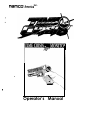
Operator’s Manual
name0
UWE QX050STM
50 INCH
Operator’s Manual
TABLE OF CONTENTS
1.0
SPECIFICATIONS
1
2.0
INTRODUCTION
3
3.0
PRECAUTIONS
4
4.0
3.1
Installation
4
3.2
Handling
4
INSTALLATION
5
4.1
5.0
6.0
Set-Up and Test
7
Figure 1: Gun Initialize Menu Screen
8
Figure 2: Gun Initialize [Standard] Screen
9
Figure 3: Menu Screen
10
Figure 4: Coin Options Screen
10
Figure 5: Game Options Screen
II
Figure 6: l/O Test Screen
12
Figure 7: Switch Test Screen
13
Figure 8: Solenoid Test Screen
13
Figure 9: Monitor Test Screen
14
Figure 10: Sound Test Screen
16
Figure 11: ADS Data Screen
17
Figure 12: Others Screen
18
MAINTENANCE
19
5.1
Monitor Service
19
5.2
Monitor Acrylic Cover, Cleaning
19
5.3
Gun Removal and Disassembly
20
TROUBLESHOOTING
NOTES ON 50 INCH MONITOR (HITACHI)
APPENDIX A:
MONITOR ADJUSTMENT PROCEDURE (MITSUBISHI)
APPENDIX B:
PARTS LIST and ILLUSTRATIONS
APPENDIX C:
WIRING DIAGRAM
23
26
name=
TK=lE CWIJUSTM
50 INCH
ODerator’s
Manual
1 .O SPECIFICATIONS
Logic Power Supply:
Gun Power Supply:
Input Power:
Overall Height:
200 Watt switching type
24 VDC, 110 Watt
120 VAC, 60 Hz, 7 A m p s max.
95”, with marquee installed.
Crated Dimensions:
Monitor
Player
Cabinet
Cabinet:
Assy:
55”Wx41”Dx87”H
37.5” W x 48.5” D x 48” H
Shipping Weight:
Monitor
Player
Cabinet
Cabinet:
Assy:
425 ibs
175 Ibs
Monitor:
Hitachi 50 inch Model 50UX22BA (S/N 101-327)
Hitachi 50 inch Model 5OUX23KA
(SIN 328-735)
Mitsubishi 50 inch Model VS-5041/42
(S/N 736-750, 1701-I 850)
Controls:
Foot Operated “Action” Pedal
Solenoid - Activated Gun
Convenience Kit:
(in coin box)
Operator’s Manual
Spare Fuse
Accessory Kit
(packed separately)
[Reference
Monitor Accessories:
(in rear of cabinet)
Operator’s Manual
Remote Controller
Installation
(1)
(1)
Section]
(1)
(1)
Modifications and/or
Note:
Specifications subject to change without prior notice.
alterations of the Time CrisizP game with kits or parts not supplied by NAMCO may void
the warranty.
WARNING
REMOVAL OF SERIAL NUMBERS AND/OR BAR-CODES FROM PRODUCT OR
COMPONENTS WILL VOID THE WARRANTY
-...
Operator’s Manual
name=
fUPiR~EKY~TM 50 INCH
namea
UKE C.RUJll~TM
2.0
50 INCH
Operator’s Manual
INTRODUCTION
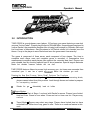
TIME CRISIS is a revolutionary new l-player, 3-D polygon gun game featuring a new dual
purpose “Action Pedal”. Players play the part of Richard Miller, a special agent assigned to
rescue Rachel, the presidents daughter who is being held hostage by Sherudo Garo and
his hired team of henchmen. Garo threatens to kill Rachel unless he is handed over the
throne. It’s up to the player to save Rachel and save the government from anarchy!
The game is composed of three areas, each composed of four stages. The time to
complete each stage, area and complete game is recorded. A comparative time
measurement compares each players time against the recorded best time. Players can
gain valuable time by shooting special hard to shoot enemies. Special targets detonate
bombs that eliminate numerous enemies with one shot!
TIME CRISIS features Namco’s proven high accuracy gun, six times more accurate than
conventional guns. It even has a special blowback” feature that simulates gun recoil.
Pressina the New Dual Puroose “Action Pedal” Performs Two Functions:
+
Duck or dodge to avoid being shot - While becoming safe from oncoming shots,
players cannot shoot from this position. Look through boxes and crates to prepare
for unsuspecting enemies!
+
Reloads the gun - Automatically loads six bullets.
Two Game Modes:
+
Story Mode - Start at Stage 1 and end with Rachel’s rescue. Players have limited
time and lives. Game is over when 3 lives are lost or time runs out. Players may
continue.
+
Timed Mode - Players may select any stage. Players have limited time but have
unlimited lives. When time is up, game is over. There is no continue feature in this
mode.
3
Onerator’s
Manual
3.0
PRECAUTIONS
3.1
Installation
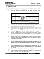
This game is designed for indoor use only.
following conditions must be avoided:
name0
UUlilR WXSTM 50 INCH
It must nor be installed outdoors. The
1.
Direct exposure to sunlight, high humidity, direct water contact, dust, high
heat or extreme cold.
2.
Vibration. The game must be installed on a level surface with levelers
properly adjusted.
Do nof install in an area such that the game would present an obstacle in case of an
emergency (i.e., near fire equipmenf
or emergency exists).
3.2
Handling
1.
Before operating the game, make sure that the main AC power hookup
includes a safety ground. This will ensure safe operation as well as
compliance with the applicable FCC and UL regulations. Measure the AC
power line voltage. Verify that the voltage source is between 110 and 125
VAC.
2.
Before replacing any parts, turn the AC power OFF and unplug the game.
3.
The game power supply includes areas where 120 VAC is present. Take
care at all times to avoid electrical shock whenever inspecting or adjusting
the game.
4.
Do not attempt to repair the Printed Circuit Board (PCB) on-site. It contains
sensitive integrated circuit chips that could be easily damaged, even by the
small internal voltage of a multimeter. Always return the PCB to your
distributor for any repairs. PCB assemblies must be returned as complete
Always return levelers to the extreme up position before moving the game.
When moving the game always remove the pedal assembly and .pack it
of high voltage inside. If trouble is suspected in the
monitor, refer to the troubleshooting guide in the back of
name=
TUflE CR!XSTM 50 INCH
Operator’s Manual
4.0 INSTALLATION
Note: Shipping damage may void the warranty. In case of shipping damage, contact your
distributor and the transportation carrier immediately.
1.
Unpack the marquee and accessories box, and identify the following items:
1 ea
4 ea
button head screws, M5 x 16. blk, w/flat and lock washers
4 ea
hex head bolts, 3/8-16 x 1-W” with washers
4 ea
3 ea
hex
2 ea
cabinet joint right angle brackets
1 ea
extension
pedal assembly
head b o l t s , 3/8-16 x 2”, with washers
flat and lock washers
hex head bolts, l/4-20 x 2”, with
harness,
for
dollar
bill
acceptor. (AP50-04271-00)
2.
Locate the rear component door panel keys attached to the back of the
monitor cabinet. Open and remove the component door panel.
3.
Verify that the monitor remote controller and manual are in the back of the
monitor cabinet. (These wilt not be needed for day-to-day operation of the
game).
4.
Connect the 12-pin,
5.
With the monitor cabinet and player cabinet approximately level, position
them such that the holes in the joint brackets will line up with the cabinet’s
holes.
6.
Install the brackets using the 3/8-16 bolts with washers. The 2 inch long bolts
go into the player cabinet, the l-1/4 inch bolts into the monitor cabinet.
Tighten them to about 20 f&lb.
7.
Connect the pedal extension harness.
8.
Position the pedal assembly such that the bracket holes align with the
threaded holes in the pedal assembly, and install the 4 ea M5 x 16 screws
with washers.
g-pin, and 4-pin connectors between the 2 cabinets.
Place the marquee on top of the monitor cabinet, making sure that the
electrical connector is hooked up. Install and tighten the 3 ea I/4-20 bolts
with washers.
With the game in its installation position, lower the leg levelers,
Plug in the main AC power cord, and turn the game ON. The power switch is
located in the lower rear of the monitor cabinet.
Ooerator’s Manual
6
name0
VURIE CRUSEP’ 50 INCH
12.
Perform the set up and test procedure. Once this has been successfully
completed, reinstall the rear access panel.
13.
(S/N 101-735 only) For best operation, perform an alignment of the 50 inch
monitor. This procedure is outlined in the section entitled”Notes on 50 Inch
Monitor”.
n a m e 0
TilflE CRUSUBTM 50 INCH
4.1
Operator’s Manual
Set-Up and Test
IMPORTANT: Pelform this procedure in the sequence indicated.
1.
2.
3.
System
initialization
is
performed
as
follows:
a.
Open the COIN door to gain access to the Service Panel
b.
Remove
C.
While pressing the SERVICE button, toggle the TEST switch ON.
d.
Release the SERVICE button.
e.
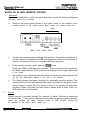
The GUN INITIALIZE Menu screen will appear as shown in Figure 1.
f.
Use the gun to select the [Standard] Initialization, and step on the
pedal to enter.
9
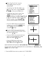
With the [Standard] Initialization screen displayed, step on the pedal to
bring-up the Gun Calibration screen.
h.
Aim the gun at the ‘X’, pull the trigger, and return to the Initialization
screen.
i.
Verify gun response by shooting in the entire area bounded in white. If
properly initialized, a green target will appear in each location hit.
hands/feet
from
the
controls.
Verify that the gun can be successfully fired several times per second.
j.
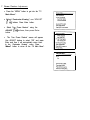
Turn the TEST switch OFF, then ON again, and the TEST MENU screen, as
in Figure 3, will appear.
From the MAIN MENU, select and adjust the following set-up options to suit
the installation requirements:
l
Coin Options
l
Game Options
l
Sound
Test
(output
level
adjustment)
Note: NAMCO recommended options are shown on test screens.
4.
Verity proper operation of game controls from the l/O TEST MENU.
namco-
Operator’s Manual
TlFlZ CROXSTM
50 INCH
f
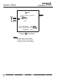
GUN INITIALIZE MENU
(al
GUN INITIALIZE [STANDARD]
(b)
GUN INITIALIZE [PmDVANCED]
TEST SW OFF:
SHOOT INSIDE SCREEN:
SHOOT OUTSIDE SCREEN:
STEP ON PEDAL:
L
!ZXIT
CHOOSE [UP]
CHOOSE [DOWN]
ENTER
I
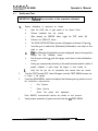
Figure 1: Gun Initialize Menu Screen
(4
See Initialize [Standard] Screen.
IMPORTANT:
USE THE [STANDARD] SCREEN TO
ADJUST GUN SIGHT DURING NEW INSTALLATIONS OR
AFTER SERVICING GUN.
(b)
Six screens are provided, to check the gun response in various zones
in the game screen.
Operator’s Manual
,
(4.
/
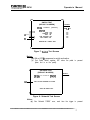
GUN INlTlALlZE [STANDARD]
b
,
SHOOT AT SCREEN
TO CHECK GUN ACCURACY
STEP ON PEDAL:
PUSH SERVICE SW:
4
ADJUST GUN-SIGHT
EXIT
GUN-SIGHT CALIBRATION SCREEN y
X
NJ
AIM AT CENTER OF THE CROSS
AND PULL GUN TRIGGER
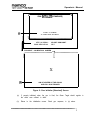
Figure 2: Gun Initialize [Standard] Screen
(a)
If properly initialized, when the gun is fired, the Green Target should register in
the entire area outlined in white.
(b)
Return to the initialization screen. Check gun response, in (a) above.
namco
Operator’s Manual
TUT QlU5USTM
COIN OPTIONS
GAME OPTIONS
l/O TEST
MONITOR TEST
SOUND TEST
ADS DATA
OTHERS
GUN INIT: SERVICE SW + TEST SW [ONj
SHOOT INSIDE SCREEN: CHOOSE [up]
SHOOT OUTSIDE: CHOOSE [DOWN]
STEP ON PEDAL: ENTER
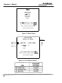
Figure 3: Menu Screen
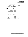
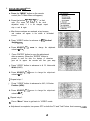
COIN OPTIONS
[DEFAULT IN GREEN]
-
GAME COST
- CONTINUE COST
FREE PLAY
DEFAULT
3 COINS 1 CREDIT
3 COINS 1 CREDIT
OFF
EXIT
SHOOT INSIDE SCREEN: CHOOSE [UP]
SHOOT OUTSIDE SCREEN: CHOOSE [DOWNI
STEP ON PEDAL: ENTER
Figure 4: Coin Options Screen
OFF
50 INCH
name=
TW=lE
Operator’s Manual
W%OSTM 50 INCH
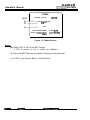
GAME OPTIONS
[DEFAULT IN GREEN]
(a)
(W
w
(4
-
w-
-
PLAYER’S LIFE
TIME LIMIT
HIT EFFECT
SOUND IN ATTRACT
-
DEFAULT
3
SHORT
RED
ON
3
MED
RED
ON
RECORD TIME CLEAR
NO
EXIT
SHOOT INSIDE SCREEN: CHOOSE [UP]
SHOOT OUTSIDE SCREEN: CHOOSE [DOWN]
STEP ON PEDAL: ENTER
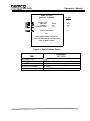
Figure 5: Game Options Screen
ITEM
(a) Player’s Life
(b) Time Limit
(c) Hit Effect
(d) Sound in Attract
(e) Record Time Clear
AVAILABLE
SETTINGS
I-9
Very Short, Short, Medium, Long, Very Long
Red, Green
ON, OFF
Select YES or NO at the “OK” prompt
name0
Operator’s Manual
UURi@ CIXOSOSTM
l/O TEST
-DIPSW4
NOTES
(4 ON w
-
12345676
[ON/OFF]
SWlTCH TEST
- SOLENOID TEST
EXIT
SHOOT INSIDE SCREEN:
CHOOSE [UP]
SHOOT OUTSIDE SCREEN: CHOOSE fDOW?Jj
STEPDNPEDAL:
ENTER
Figure 6: l/O Test Screen
Notes:
(a) See Switch Test Screen.
(b) See Solenoid Test Screen.
(c) Returns You to Main Menu.
DEFAULT
I-6 OFF
50 INCH
nameoUWUR
CAUdOJTM
50 INCH
Operator’s Manual
\
/
SWITCH TEST
[DEFAULT IN GREEN]
DIPSW4
12345678
DEFAULT
[ON/OFF]
SW l-8 OFF
SWlTCH
(a)
W
3
COIN:
SERVICE:
TEST:
GUN TRIGGER:
FOOT PEDAL:
OFF
OFF
ON
OFF
ON
OFF
OFF
OFF
OFF
OFF
SERVICE SW + PEDAL: EXIT
J
L
Figure 7: f&itch Test Screen
Notes:
(a) ON or OFF ini response to switch activation.
(b) Foot Pedal Switch registers OFF when the pedal is pressed
[when foot is on the pedal].
SOLENOID TEST
[DEFAULT IN GREEN]
DIPSW4 1 2 3 4 6 6 7 8
(4
[ON/OFF]
DEFAULT
SWl-8
OFF
PULL ON GUN TRIGGER TO ACTION
STEP ON PEDAL: EXIT
Figure 8: Solenoid Test Screen
Notes(a) Gun Solenoid “FIRES” once, each time the trigger is pressed.
Operator’s Manual
/
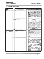
MONITOR TEST
!iQIEi
GRADATION PATTERN
CROSSHATCH PATTERN [CRTI
CROSSHATCH PATTERN [PROJECTOR]
It;
(a
b
(d)
w
.
WHITE WlNDOW [HI
WHITE WlNDOW fMj
WHITE WINDOW &]
INTERLACE PATTERN
VIEW ANGLE ADJUST [CRT]
VIEWANGLE ADJUST [PROJECTOR]
FULL WHITE
EXIT
SHOOT INSIDE SCREEN: CHOOSE [up]
SHOOT OUTSIDE SCREEN: CHOOSE [oOW?4j
STEPONPEDAL:
ENTER
Figure 9: Monitor Test Screen
14
namco7r’Wi ~ $AIJISTM 50
INCH
(a) Gradation Pattern
(b) Crosshatch Pattern
[CRT]
(c) Crosshatch Pattern
[Projector]
(d) White Window
P-L M. Ll
(e) Interlace Pattern
(f) View Angle Adjust
[CRT]
(g) View Angle Adjust
[Projector]
(h) Full White
* Note:
ODerator’s Manual
Monitor Test Descriptions
Four bars (G, R, B, W from top to bottom) with 15 gradations
each are displayed.
Green Grid is displayed. Lines should be reasonably straight,
undistorted and uniformly bright across screen. (If not contact
Namco. Also, see Troubleshooting notes).
White Grid is displayed. This can be used to check monitor
convergence. Slight non-convergence (R, G or B showing) is
normal.
Used to check light output (contrast) of screen. WHITE [H]
reading should be 40 to 80 f&L. Monitor contrast adjustments
accessible via the Remote Control Monitor Setup Menu.
A pattern of line blocks is displayed, used for indication of
vertical hold adjustment. On the center pair of line blocks, the
top line of the right block of lines should be aligned with the
space between the first and second lines of the left block.
Green Screen, with black frame, used at factory to set the
VERT height, HORIZ width, and VERTIHORIZ centering.
Crosspoint should be in the center of the screen. Horizontal
width should be set for slight overscan. If adjustment is
required (Ex: New Monitor). Refer to Monitor Adjustment
Section.
Black Screen, with white frame. Crosspoint should be in
center of screen.
Used to check White Screen light output. (Nominally 15-20 ftL).
Push Start to Return from Monitor Test Screen to Monitor Test Menu.
Operator’s Manual
SOUND TEST
[DEFAULT IN GREEN]
MESSAGE: CIUATTRO
lb)
VER5.2
VOLUME
FRONT L SP 50 [MAX631
FRONT R SP 50 [MAX631
REQUEST
SONG NO. 000
EXIT
PUSH SERVICE SW:
SHOOT INSIDE SCREEN:
SHOOT OUTSIDE SCREEN:
STEP ON PEDAL:
PLAY/STOP
CHANGE [+I
CHANGE [-I
ENTER
Figure ICI: Sound Test Screen
16
DEFAULT
50
50
namco’
Operator’s Manual
TODK WSUSTM 50 INCH
ADS DATA
TOTAL COINS
START COINS
CONTINUE COINS
TOTAL CREDITS
0 [ csvc 0000 ]
0 [ csvc 0000 ]
0 [ +svc 0000 ]
0
ON TIME
PLP‘Y TIME
TOTAL BLOW BACKS
STEPS ON PEDAL
0:00’00”
0:00’0D”
0000
0000
STORY GAMES
[CONTINUES
T.A. VIMEO] GAMES
-
(a)(b)-
000
0001
0
STORY START/END
STORY GAME OVERS
T.A. ITIMED] GAME ENOS
2
1
INITIALIZE
EXIT
SHOOT INSIDE SCREEN: CHOOSE [UP]
SHOOT OUTSIDE SCREEN: CHOOSE IDOVVFI]
STEP ON PEDAL: ENTER
Figure 11: ADS Data Screen
(a) Additional Data Screens
(b)
Select YES or NO at the ADS Prompt.
‘YES’ will reset all game data to 0000.
name0
Operator’s Manual
IMilE WXP’ 50 INCH
OTHERS
NOTES
ROM VER. 96101108
18:57:09
EEP-ROM INITIALIZE
PCS TEST
EXIT
SHOOT INSIDE SCREEN:
SHOOT OUTSIDE SCREEN:
STEP ON PEDA.L:
CHOOSE [UP]
CHOOSE [OOWN]
ENTER
Figure 12: Others Screen
Notes:
(a) Select ‘YES’ or ‘NO’ at the OK? Prompt..
If ‘YES’ is selected, be sure to recheck gun initialization.
(b) Video and DSP Tests are provided for factory service personnel.
(c) To EXIT, push Service Button + Pedal Switch.
18
nameo’
TUl=WZ CIXUBI*STM?
50 INCH
5.0
MAINTENANCE
5.1
Monitor Service
Operator’s Manual
The 50 inch monitor does not require regular maintenance, and there are no userserviceable parts inside.
If a replacement Mitsubishi monitor i s supplied for your game, perform the Monitor
Adjustment Procedure in APPENDIX A. This will ensure that it is set up for PowerOn-Restore and that the screen is properly sized and centered for your Time Crisis,
game.
If a monitor malfunction occurs while your game is under warranty, contact your
Distributor and/or NAMCO for assistance.
For out-of-warranty repairs, contact your nearest authorized Hitachi or Mitsubishi
Service Center.
5.2
Monitor Acrylic Cover, Cleaning
When
cleaning
becomes
necessary,
follow
these
steps:
1. Rinse cover with lukewarm water.
2. Wash gently with mild soap or detergent and lukewarm water, using a soft cloth
or sponge. DO NOT SCRUB or use brushes or squeegees.
3. Rinse again. Dry with a soft clloth or moist cellulose sponge to prevent water
spotting.
4. To remove wet paint, glazing compound, or grease, rub lightly with a good grade
of VM&P naphtha or isopropyl alcohol, then wash and rinse. DO NOT USE
GASOLINE.
Compatible Cleaning Agents
Aqueous solutions of soaps and det:ergents
Fantastik’
Neleco-Placer
T o p Job*
M r . Clean’
PineSol 4
LysoP
Formula 409’
Joy*
Windex5
Organic solvents
Aliphatic hydrocarbons
Kerosene
Naphtha (VM&P grade)
Petroleum spirits
Alcohols
Methanol
Isopropyl alcohol
Graffiti removal
Butyl Cellosolve (For removal of paints, marking pen inks, etc.)
Polishing
Johnson’s Paste Wax
Mirror Glaze Plastic Polish
’ TM Clorox company
““American Cyanamid
N o v u s P l a s t i c P o l i s h #I and #Z
ITM Procter & Gamble
‘“Sterling
Products Company
Drugs
5m Drakett
1s
name0
Operator’s Manual
5.3
TUDE CROJUSTM 50 INCH
Gun Removal and Disassembly
section 4.1) after replacement of gun components or assemblies.
5.3.1 Opening the Gun
M3XlO Cap Hd
Gun Slide
Gun Cover
Figure 5-l
Opening the Gun
I. Remove the four M3 x 10 cap screws and one M4 x 25 button head screw that
attach the gun side halves.
2. Remove the gun side halves.
3. With the gun assembly laying on its left side, remove the three M4 x 10 button
head screws, one M4 x 25 button head screw, and one M3 x IO cap screw.
4. Lift the right gun cover off the gun assembly. Be careful not to scratch the lens.
[Note: When reassembling the gun, the convex side faces out!]
20
nameo’
UWiE fJXUSUSTM 50 INCH
Operator’s Manual
5.3.2 Replacing the Gun Solenoid
I, Remove the gun covers and gun side halves.
M4 X 6 Cap Screw
?
Slide
t Solenoid Bracket
Ground
Wire
Lock
Washer
hi3 X 8 Cap Screw
Figure
5-2
Gun Solenoid Assembly
2. Disconnect the solenoid connector.
3. Remove the M3 x IO cap screw attaching the solenoid/slide assembly to
the left gun cover.
4. Remove the M3 x 8 cap screw and washer attaching the ground wire to
the solenoid bracket.
5. Loosen the solenoid nut.
6. Pull the solenoid away from the bracket.
7. Remove the two M4 x 6 cap screws attaching the slide guide to the
bracket.
8. Remove the solenoid plunger and spring.
Cberator’s
namecr
UUVilE CR030~TM
Manual
Figure 5-3
50 INCH
Solenoid Plunger Detail
9. When reassembling the solenoid, pay particular attention to the order of
E-rings and spacers. Make sure the solenoid harness faces downward
upon reassembly.
Figure 5-4
Solenoid Reassembly
5.3.3 Trigger Switch Replacement
1. Remove the gun covers and gun side halves.
2. Remove the two screws that attach the microswitch to its bracket.
3. Remove the two connectors that attach the trigger microswitch to the gun
harness, and replace the switch.
4. Upon reassembly, check the condition of the trigger spring.
namco-WE CJXOSUSTM
Operator’s Manual
50 INCH
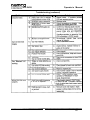
6.0 TROUBLESHOOTING
Solution
Probable Cause
Problem
10 AC power.
lo video or sound.
T=
Check main AC fuse i n rear of
cabinet. If fuse is OK, check voltage
~~mcc
YVlV””
Vo DC power.
\lo video, but
nonitor is poweredJP.
1)
2)
2)
Jideo input to monitor is
disconnected, or bad video
cable.
1)
Monitor problem.
2)
innnIt cirla
F M I fi!tp~, .ShnU!d
aany”.
“,“” nf
“, -....
be 115-12OVAC.
If no voltage, then
ON/OFF switch is bad, replace. If
EMI filter input voltage is good, check
voltage at the output (load side) of
EMI filter. If no voltage, EMI filter is
bad, replace.
Verify that monitor
power cord is plugged in.
Check AC inout ~luo on switching
power supply. ‘Verify I% switch is ON.
Check DC output voltage at g-pin
connector. RED to BLK should be
5+/-.15VDC.
ORG to BLK should be
12VDC -0/+1.8VDC.
If 12VDC is bad,
check for output shorts by removing
load connectors one at a time (ref.
overall wiring diagram in Appendix). If
loads are OK, or if 5VDC is out of
tolerance. reolace
power supply.
(Note: output is non-adjustable).
that S-VIDEO cable
is
Verifv
connected between back of monitor
and RGBlNTSC
PCB (small board on
component shelf). Verify that correct
input channel is selected on monitor.
Should be EXT-I S-VIDEO. Check
usina remote control INPUT button to
toggle through selections.
Verify monitor is OK by selecting ANT
Input, using remote control. If OK,
snow or raster should appear on
screen. If bad, DO NOT ATTEMPT
TO REPAIR MONITOR OR THE
MANUFACTURER’S
WARRANT-Y
WILL BE VOIDED. (Note: lf warrant)
service is required, contact NAMCO through
your Distributor. In the U.S., repair sewice fo
is provided through the
yO”r monitor
nationwide
network 0
manufacture<s
authoriied TV repair centers. For in-warrant!
repairs outside the U.S., contact NAMCC
NAMCC
Customer Service for awstance.
reserves the right to repair or replace defectin
monWrs at its discretion. Advance replacemer
monlton cannot be provided to IocabOn!
outside the U.S. and U.S. terrltones).
23
ODerator’s
name0
Manual
TWX WSOSTM 50 INCH
Troubleshooting (continued)
connected on SS22 P
Verify that RGB and SYNC signals are
present at J9 pins 1.2,3,4 w.r.t. pin 5.
N O T E : D O N O T ATEMPT T O
REPAIR PCBs OR WARRANTY WILL
BE VOIDED. If main PCB rack is
PCB (mounted on top of main PCB
rack). Check continuity of cables from
J2 to RCA jacks on back of monitor.
Jacks should be connected to EXT-1
24
name=0
UURlE CWSTM
Problem
50 INCH
Operator’s Manual
Troubleshooting (continued)
Probable Cause
or is out of adjustment.
Solution
ODerator’s
Manual
NOTES ON 50 INCH MONITOR (HITACHI)
1.
Alianment
Upon initial installation, or after the game has been moved, the following alignment
procedure should be performed.
a.
Remove the cover plate located in the lower center of the monitor cover,
providing access to the monitor service panel. Locate the remote control unit.
INPUT 3
I
I
I
S-VliDEO
Hitachi
2.
Front
Service
AlJ’OIO
Panel
b.
On the service panel press the Magic Focus button. The monitor will perform a
self-test, where it correlates the RGB convergence to values that are stored in
memory. Allow the test to run to completion without interruption.
C.
On the monitor remote control, press the m button.
Verify that VIDEO: [S-IN] has been selected. (This sources the video signal from
the Namco game-board). The source input is displayed in the upper right corner
of the screen.
d.
Re-install the cover plate and place the remote controller in a place where it will
not get lost. (Recommend attached to the rear of the monitor).
e.
The Hitachi monitor has been configured for automatic power-on-restore. This
means that the monitor will automatically power-up whenever the game’s main
power supply is turned ON. The remote control is not needed for day-today
operation. When “recycling” the main power, always allow at least 10 sec. of
OFF time for the circuit to reset.
Service
Repair service is provided through the network of Hitachi Electronics authorized
service facilities. If the monitor requires service while the game is under warranty,
contact your distributor and Namco Customer Service at (800) 326-4263. Repairs will
be performed at the service facility nearest you.
26
name=
TUflE ‘WsSUSTM
50 INCH
APPENDIX A: MONITOR ADJUSTMENT PROCEDURE
(Mitsubishi VS-5041!42)
Operator’s Manual
WITH MITSUBISHI MODEL 5041 OR 5042
CAIl77ON:
The TV power plug will fit into the the power outlet only one way. DO NOT force the
power plug into the power strip.
1. Make sure the TV is OFF.
2. Plug the Test Fixture S-VI-IS Cable to the DIN adapter of the TV front panel.
3. Using the remote control turn the TV ON. Let the TV warm up for a few minutes (3-5 minutes).
4. Press the (? $ ) INPUT buttons to change to SYNC - 3 (S-VIDEO) on the TV screen.
5. Color Display Ad/ustments;
l
Press the “Menu” button on the remote control.
The “TV Main Menu” will appear on the screen.
Y
1
* Select “First Time Set Up” using the
ADJUST (? 4 ) buttons and press
ENTER button.
l
You will see the “First Time Set-Up” screen.
Select the “Align Colors” using the ADJUST
(?+ d) bu tt ons; then press the Enter button.
You will see “Align Colors” screen. Press
“VIDEO” for the first time. You will see
%VHITE” crosshairs on the screen with t RED +
on top of the crosshairs. At this time you are able
to adjust the vertical Red crosshair to line-up with
“WHITE” crosshairs; using ADJUST (? 4) to
move the vertical crosshair to the Left or Right.
l
l
Press the “VIDEO” button for the second time
to advance to the vertical Blue crosshais; using
ADJUST (? 4) to move the vertical Blue
crosshair to Leti or Right.
* Press the “VIDEO” button for the third time to
advance to the horizontal RED crosshair. Adjust
with ADJUST (? A) button.
l
l
Press the “VIDEO” button for the fourth time to
advance to the horizontal BLUE crosshair.
Adjust with ADJUST (T 4) button.
Press the VIDEO button the fifth time to
gc back to the “Align Colors Menu”. Press
“Menu” button to exit the “N Main Menu”.
t
w
6
MAKE SURE BOTH RED AND BLUE ARE ALIGNED AND FORM A WHITE CROSSHAIR.
DO NOT LEAVE THE WHITE CROSSHAIRS FOR A LONG PERIOD OF TIME, SINCE ’ ‘. CAN
DAMAGE THE PICTURE TUBES.
6. Press the MENU button twice to go back to the “TV MAIN MENU”.
2
7. Power Restore Adjustment;
Press the “MENU” button to get into the “TV
l
Main Menu”.
Select “Customize Viewing”, use “ADJUST
l
(? -1) buttons. Press Enter button.
Select “Use Power Restore” using the
l
ADJUST (? &) buttons; then press Enter
button.
The “Use Power Restore” screen will appear.
Use ADJUST buttons to select “ON” and press
Enter and then it will automatically return back
to the “Customize Viewing” menu. Press
“Menu” button to return to the “TV Main Menu”.
l
8. DJent
Mode:
a. Press the “MENU” button on the remote
control (the TV Main Menu will appear).
b. Press the button “2”, “3”, ‘Y’, “7” in that
order. (The screen will change to the circuit
adjustment mode). If it is not changed, repeat
step a and b again.
c. After these numbers are entered, a text screen
and numbers will appear in the middle of left-handed
screen.
d. Press “VIDEO” button to advance to #lo, Vertical
Height (VHT).
e. Press ADJUST (? &) arrow to change the adjustment
value to “ 50 “.
f.
Press “ENTER” button to save the adjustment
data in memory. When the “ENTER” button is
pressed to save the data, the displays of characters
goes red for approx. two seconds and then goes away.
g. Press “VIDEO” button to advance to # 12, Horizontal
Width (HWD).
h. Press ADJUST (? &) arrow to change the adjustment
value to “ 24”.
I. Repeat step f.
j.
Press “VIDEO” button to advance to # 43, H-Center
Position (HPH).
k. Press ADJUST (? &) arrow to change the adjustment
value to “ 9 “.
I. Repeat step f.
m. Press “Menu” twice to get back to “VIDEO” mode.
n. Adjustment is complete, turn power OFF on both the TV and Test Fixture. And remove $-cable
4
NOTE:
These “initial data” are the initial values of that adjustment These initial data may
not be correct for the normal performance of each TV monitor. The visual check is
necessary.
Operator’s Manual
APPENDIX B:
PARTS LIST and ILLUSTRATIONS
I
Major Assemblies (Front View)
Page
Major Assembiies (Rear Viewj
B-3
$5
Monitor Cabinet Assembly (Front View)
Monitor Cabinet Assembly, (Rear View)
B-6
B-7
Monitor
B-8
Cabinet
Assembly
parts
list
Monitor Cabinet Assembly parts list (con?)
Control Panel, Blue Gun & Tether Assemblies
B-9
B-10
Pedal Assembly w/Harness
B-l 1
PCB Set Assembly
B-12
List of Harness Assemblies
Power Plate (AC) Assembly
Service Panel Assembly
Blue Gun Assembly (detail)
(
B-13
1 B-14
7
(
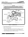
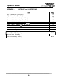
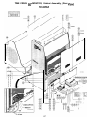
TIME CRISIS 50” MONITOR, Major Assemblies
(Front View)
- Monitor Assembly
Monitor Cabinet
Assembly
”
,-
‘..
Gun
_.
Assembly
TetherAssembly
Control
Assembty
Holster
Panel
Assembly
coin Door & Service
Panel Assemblies
Player Cabinet
Assembly
Assembly
B-3
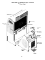
TIME CRISIS 50” MONITOR, Major Assemblies
(Rear View)
Monitor
_ . ~ Power FiY
’ jl
:upp/y
\
8-5
Assembly
Power suppty
Assembly
,^,,
,I_. .-.._I
Access
NTSC PCB
Gun Drive PC8
U.L. Bracket
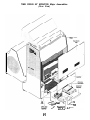
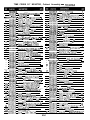
TIME CRISIS 50” MONITOR, Cabinet Assembly (Front View)
TCOI-04709-00
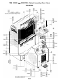
TIME CRISIS 50” MONITOR, Cabinet Assembly, (Rear View)
TCOi-O4709-00
TIME CRISIS 50” MONITOR, Cabinet Assembly - nwwog-oo
1
TCO5-04786-00
MONITOR C A B I N E T ASSEMBLY
3
VGlC-04741-W
Grill. Ptiorat~
lB&m 01 Mmlor
CaL~rrt
US s'WI?.S)
1
46
VGZO-02865-05
Washer, Flat. #iO.Black.Dxlde
2
47
TClO-04909-00
Plate. Access,&gic
11
Focus B u t t o n (HIT 2281 1
Focus Button(HIT23K)
1
4
TC40-04MO-00
___..
5
VG24-04933-00
DeGl. me Panel
2
47a
TClO-05108-00
Plaa. Access.
Cask:,
8
48
VGZO-02888-04
silew
VG20-028M.12 6
Scr:w.Hex-Hd.1/4-20
32
49
TC40.04E48-GO
Dm/, Front Panel, Monrfor
32
50
Label, U.L. Time Cmis, 50” Monitor
1
32
Label, FCC
1
4
51
y
TC46-04844-00
VG46-02653-00
V~~~~~~&.~~
4
53
v646-02655-00
16
54
VG44-03968-00
16
55
MARPUEE ASSEMBLY
Cabinel, Marquee
1
3
3' (4 lor monitor & 4 lorplayercabmets)
xl'.Sieel.Z~fl~
1/4'.Sleel,Zinc
Magic
Btn-Hd,Tm~Prf.Y&32x1/4'.Blk.Dx(HITanly)4
VGZC-02862-37
Washer.Spl~l-Lock,
8
washer,
9
10
VG20-02864-37
._ _ _ ___ _ _ _ YWU-"JIW-"U
RLlO-02683-00
11
VG2C-0286&12
X:w,Hex-Hd..1/4-20
7
VG20-02862-07
Washer. Spill-Lock,
8
VG20-02864-07
wziw Rat l/4'. SW Arc
16
56
TC05-04765.00
TC63-04792-00
12
VGlO-04690-00
Grill..-r-m
Sneaker. Perforated
~.
Wnnd ._.._,_
liRr?,R' ,_.__
Mark,_.__
~I,,P
sm.., w Pm-HI1
". .I, .."l_,
2
57
V( ;20-02860-32
Boll. Hex, 114-20x
Z',Steel,Z~nc
Steel, Zinc
Flat,l/4', St&Zmc
iaJ Le.&, %X3x2%2
Plate,LeQ
pwnlu&2&rUi&j
LeVeler.1/2-13
xl',St.%l.Linc
l/4'. Sleel. Zinc
Labe:,
1
(NAMCO)
7
B: KGRNNG
Label.
Semi
1
Number
-Label. CAUTION, “S&-vi~e Penonnel ONL y’
1
1
13
VGZO-04114-X
R_
8
VG20-02864-07
Washer, Flat, l/4'.
14
15
TC63-04926-00
TrXl-04725-m
COIN DOOR ASSEMBLY, 2 SLOTS w/HARNESS
1
7
VG20-02862-07
Washer.
Harness Coin Door & Servce.50
Mon~lor
1
58
TC95-04855.00
Acrylic, Marquee Cover, 50” Monitor
1
16
17
X50-04726-00
0005-04768-00
Hamess.Co~n
Exl.,5C'Mamtor
1
59
TC40-04650-01
Sly~?ne,
Tune Cnsa Marquee
1
SERVICE PANEL ASSEMBLY
1
60
VGlC-04745.00
Retamer.
Marcuee.
18
VGZC-02896.06
Screw.Pan-Hd..Phillos.68-32
2
41
VG20-02906-10
Screw, Pan-Hd. Wood, 18~5/8'.Black.Oxide
19
TClO-04796-00
Bracket, Joint, Monibx~layer C a b i n e t
2
61
VGlO-04746.00
Reialner.
20
VG20-04091-32
Boh~~.~16~2',Bli(D~~(p~~~)
4
45
VG20-02907.16
Scrw Pan-Hd. lO-24
21
VGZO-04091-20
ec& ~~.~16xl-l/4'.E~~(Mcnitcr~)
4-
62
VG90-04959-00
Plastic, Marquee, Left Side (Red)
4.
-.
1
22
VGZO-02865-09
Wzsher.
8
63
VG90-04959-01
Plastic, Marquee, Right Side (Red)
1
71
VGZO-02863-W
Washer.Sol~l-Lack.
41
24
TCO5-0469500
COMPONENT PANEL ASSEMBLY (Bottom)
vi ;20-02906-10
-.~
TC40-04924-00
Door & Stwce
x 3/8'.Sleel,Zinc
Flal. 3/8’, Black. Oxide
3/8’.Hlack.
Dxlde
a
-
64
1
SpINI-Lock.l/4'.
Marquee.
1
1
x l'.Black.Dx~de
Screw, Pan-Hd,Wood.#8
x 5/8'.8lack,Oxlde
Decal, Marquee 9de (NAMCO) Red/Black
x63-04887.00
PaneI.Wood
65
VG57-03871-00
Lamp Fluorescent, 36”
VG26-0460%00
Lti,~aikcessao0r
66
VG57-03870-00
Fixture. Fluorescent. 36
27
TC05-04957-00
REAR ACCESS DOOR (Middle)
67
VG44-0385&00
Label
”
“c1Lnd7PL”n
.” ” “.. _.
_GnlI Pwlnr~lpil
-.- -.--.Hack Panel fusestaples)
L&e/, Lamp Vaiue, 175V. 3OW
Screw.
SlFv-4 7i"P
Pan-Hd.Phlil"<
,~ ,*",tl"-?d
," _ r?'
.._ 1."~,_..._
-&her. Flat. #:O. Steel. Zinc
4
Lower
25
vr,zo-oz897-48
26
3
Too
26
1
3
Steel. Zfnc
10
7
2
2
Lamp Replacement
- 2
7
2
I6
68
VG44-02644-14
127
VGZO-02897-16
Scrsw Pan-Hd.XlC-24xl'.Steel.Z1nc
4
6
69
VGZO-04772-05
Nut, Polymer, #lo-24.
4
Steel. Zinc
29
VG20-02864-05
30
TC63-04979-00
PANEL MONITOR ACCESS (Top)
1
31
VI ;20-02864-05
Washer, Flat. #lo, Steel, Zfnc
4
31
VG20-02897-4a
Scrw.
4
70
VG95-02117-W
Grommet. 718'. Dia. Hole
2
4
Pan-Hd.Ph~lips.Y10-24x2'.Sleel.Zinc
32
VGZO-02864.i5
Washer. Flat. f:O. Steel, ZIOC
4
71
GT57-02219-00
Lock Fluorescent
33
VG85-04816-00
MONITOR, REAR PROJECTION, !%“(HITACHI) 1
72
T( :50-04914.00
Harness.Fluo!escenl
33a
VGa5-05446-W
Monitor.RearPro@on,50'
(HlT5CUx
1
73
TC50-C4913-00
Harness.Fluorescenl
'*?h
vGa5.03945.00
Mwltor.
iMlTSVS-5041/421
1
74
TC05-04787-00
COMPONENT ASSEMBLY
1
3E
TC50-04720-00
Harness. Speaken
inntshowni
1
15
TC63-04841-60
Shelf. Component Board
I
37
TC50-04721.00
w "_Mnnllnr
m-k,
Harness, to Tvnmk.rc
S,.w..
..~....~. mm
,..-..,1~.,
1--
76
VG68-04690-00
Power SUPPlY, 24v (Ior
sun)
1
3a
AP50-03425-00
Harness. AC Power
1
77
VG20-031aO-08
Sew. Pan-Hd., M3x 8.Steel.Zlnc
4
39
20
VG51-04028-02
VG95-04752-00
1
78
VGlO-04814-00
Bracke1.~4V,PowerSupply
2
1
79
VG20-02903-
4ca
Tc95-0510%03
Caale. Super VHS Video 1M
Cover, Monitor , lenrlic
.- , -,1NlT, 77271
- - -,
nrn,,,r
lUlT71YL*,l,,.I,,"""lI,lC,
h"lTS Wdlld?,
,,,, 1(11,,
her. Momtoi ,"L1
1
RO
~~
Cl
42
VGZO-02900-1C
TC,C.O4747.,,0
4
1
43
VGZO-0290:-l;
Sc:ew. Pan-Hd. PhilIps. 88 x5/a'. Black. Oxide
&n,"~r
Il""0r
.,",,/",, I*_-,
Cr..,,,
9,%-b ““.V”
il",rk
ir,iw. o/s D,n.url
mu, ,,,,, Ph,,,r,i
*,. ,” ,".7A"l,d'
LTn”,T .WIYIII,
c4
iClO-04748.CO
44a
x10-05107.co
Feralner.
Er.tl,nPr
44b
TClO-05107.Cl
~45
VGZO-02901-16
RearProlectlon.50'
5(1' Momtor
23BA)
-
1
Exiensmn
1
Screw. Pan-Hd. Wood.#Bx 5/8'.Steel.Z1nc
4
TC50-04735-00
Harrzss.AC
lnwl124V),
5o'Momtor
I
81
TC50m04732-00
Harness.24V
Power.51)'
Monitor
1
a2
VGSIl-01
-5
83
1
10
Power Supply, Switching, 200W
1
VGlO-04612-00
Eracksl.
1
a4
VG20-02903-13
SC&
1
a5
CY50-03975-00
Hacless.P~~erCord.Left
/CUl,llLl, ""J", II I\, Cl/Xi
1
a6
TC50-04724-00
Harness DCPawer.50'Momlor
Sew Pan-Hd lo-24
6
87
TC50-04727-00
~~~~,frcrr
Lower lHlT228,
P" iHlT71Ki
MlTS5041:42)
xl',Elxk.Ox~de
615-00
Mounirng
Power Supply
Pan-Hd.'Nood.1ax5/B',Sl~l.ZlnC
PowerSupply
DC Pow lo RGBMTSC
4
.~
1
1
.__
FCB. 5U" Moniiol
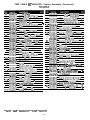
TIME CRISIS 50” MONITOR, Cabinet Assembly (Continued)
TCOl-04709-00
-
88
VG78-00476-00
Filter, EMI,
35
VG2&02903-l?
Screw, Pan-Hd ,Wood.
89
TCW04733-00
Harness,
90
VGlO-03811-00
Brackel,Ground
91
35
VG20-02700-05
Nut. Kep. RlO-24.
VGZO-02903-Q
Screw,Pan-Hd..Wooa,
92
VGZO-03579-00
Slandoff
93
VG84-m792-00
PCS, NTSC
94
TC50-04727-0a
Hamess.RGBto
95
TCO3-04886-00
P C S , G u n Drive
56
TC50-04729-00
Harness, Gun Dr~veto
9'
98
X50-04728-00
VG15-04947-00
Hamess.CPU
100
TC05-04788-00
101
102
VGZO-02896-36
VGZC-02862-04
.25 Tab
1
124 TCSO-04730-00
Harness Gun & Pedal Exlens!an.
2
96
mo-04729-00
Harness. Gun Dri~eto
1
16
TC50-04726-00
Harness. Corn Door&
SerweExt
Lug. U.L.
1
T&O-04725-00
Harness, Coin Goor&
Serwe,
Steel. 21nc
2
15
125
TC50-04722-00
Harness,Front SpeakerExtenslon.50'
2 -
176
TCIO-04744.00
Bracket. Lower. Control Panel
1
12
127
VGZO-02897-16
Screw,Pan-Hd. lO-24xl',Sleel,Zinc
3
1
31
VGZO-02864-05
W&her.
1
129 TC90-04738-01
Control Panel w/Speaker
1
130
vG70-02889--16
Screw.Bln-Hd
1
46
VGZO-02865-05
Washer, Flat, tlO.Black.Oxrde
1
1
132
iC40-04639-00
Decal,
133
CY54-03866-00
Speaker.4 Ohm,ZOW,4'Sq.
2
PCBOAROSETASSEMBLY.TlMECRlSlS
1
85
VGZO-02903-10
Screw.Pan-Hd.,Wood,~8~5/8'.Stml,Zinc
16
Suew.
2
18 x314'.
EMlOut.
Sleel,Zlnc
Monitor
18x3/4'.Steel.Z1nc
PCB
NTSC PCB.50'
Montlor
Gun & Pedal. 5o'Monltor
to Gun DrivePCB.50'
PCS, Video
Monitor
Ampliller
Pan-Hd.. Fl?1l1ps,#&32
x2-114'. Steel, Zinc
103 VG20-02864-04
136
TClD-04797-00
~..
137
AP50-03385-00
5r Monitor
1
Gun &Pedal.% Monitor
1
.50' Monitor
1
50' Mondor
1
Mowlor
Flat, (10, Steel,Z~nc
1
3
Holes (plastic)
.Tmp-Prl.#lO-24
x 1'. Elack.Oxide
1
9
9
1
me/. instluctian
'Washer, Flat. IS. Steel, Zinc
16
Grfll. Speaker
2
Washer.Spilt-Lock,bE.Steel.Z~nc
2
i03 VGZO-O-2864-04
104
VG55-00060-00
Washer, Flat, I& Steel, Zinc
2
Harness.Speaker
1
Fan. Axial,llSlAC
1
138
PBO3-03141-01
BLUEGUNASSEMBLY
1
105 GT55-02248-00
106
VGiO-04712-00
Grill. Fan
Nut Well. 18-32
1
124
TC50-04730-00
Harness.Gun
1
4
139
P890-03080-01
Holster,
4
130
VGZO-02889-16
Scr~~.Etn-Hd.Tmp-Prf.110.24x
wn-nxfiw
TC05-04715-00
Washer
Flat. #lO.Black.
TETHER ASSEMBLY
x l/Z'. Steel. Zinc
x2-1/2"'.
Sl~l.Z~nc
& Pedal Extension
Gun
1
107
VGZO-02896-40
Screw.Pan-Hd.18.32
103
109
VGZO-02864-04
RV50-04359-00
Washer, Flat. t8, Steel. Zinc
Harness, to Fan
4
AR
1
142
110
0005-04764-00
POWERPLATEASSEMBLY
1
143
111
VGX-046@1-00
PI&Power
1
46
85
VGZO-02903-10
Screw Pan-Hd.RB
4
145 11620.02903-10
mte, COYB(, w mt, wkta ~XWS ctt mt hale)
i
113
VGZO-02700-05
Kepnut.
1
VG5i-01232.06
PowerCord.3Cond.Yi8Awg.S1T.6Ft
VGZO-02864-05
VGZO-02701-05
Washer, Flat, X10, Steel, Zinc
-Nul. Hex #lo-24,Steel.
Zlr!c
4
114
31
147
148
TCBO-04671-00
FOOTPEDALW/HARNESSASSEMBLY
1
2
AC
x 5/B'.Steel,Zinc
Hex.XlO-24.Steel.Zinc
1
w/Molded Plug (forreplacemenTose
115
CY50-03998-00
116 RV50-04359-00
~117 VG78-00198-00
ii8
119
VG78-00199-W
TC50-04734-00
1 2 0 TC05-04791-00
121 TC63-04794-00
TC4o-a4649-a0
122
~
.173
TC40-0464%01
NOTE: Hem 122
Harness.Power
Power Supply
149
150
TC40-04&X
TCIO-04716-00
Decal, Pedal lnstruclion
Bracket. Foot Pedal
Femte
2
143
VG20-02889-20
Screw.Bln-Hd:;
4
152 VGZO-04930-16
153
VGZO-02863-05
154
TClO-04813.00
Screw. Ski-Hd..
85
VGX-02903-10
Screw, Parllcle-Board,
124
TC50-04730-00
Harness, Gun & Pedal Extension.
Ferrite
[noi shown)
Harness,Ma1n.50'
MOnltor
--
1
PIAYERCABINETASSEMBLY
Cabnet, Player
1
1
Decal, S,de&"ei.
Pedestal Left
1
LIecal, 8de Panel. Pedestal. Rfoht
1
is lided under Reference Oocument,
and is not part 01 Power Plate Asemhv
B-9
Washer,
imp-Pd, tlO-24
Phdrps,
Split-Lock,
Bracket,FootPedalSupport
4
4
1
Screw,Btn-Hd,Tmp-Pif, tlO-24x
-Washer. Flat. 110, Black, Oxide
4
Bead {norshowfl)
1
Oxide
Ferrite Bead (notshown)
Housing
Cord, Rrght
oniy)
VGZO-02889-20
VG20-02865-05
!'.Blk.Ox
l-114'. Blk. O x 4
4
4
x l-1/4'.Blk.Ox
4
Tmp-Pd.
M5 x16. Blk Ox 4
#lO.Black&de
3
1
.-____
#8x 518‘. Steel.Z~nc
4
50"
Monitor
1
TIME CRISIS 50” MONITOR, Control Panel, Blue Gun 81 Tether Assemblies
TC90-04738-01,
1
TC90-04738-01
Control Panelw/Speaker
2
VG2&02889-16
Screw.Etn-Hd..Tmp-Prf.#lO-24x1',
3
VGZO-02865-05
Washer. Flat. 110,
4
TC4h7463P00
5
PBO3-03141-01
& TCO50471500
Holes (plastic)
1
17
VGZO-02865-05
Washer,Flat,tiO.
Black.Ox$de
9
16
TC05-04715-00
TETHER
9
19
PB20-03154-00
Cham.
cml. Panel. instrKlm
1
20
PEtlO-03153-00
CIIP
CY54-03866-00
Speaker,4 Ohm.20W.4'Sq.
2
VGZO-02903-10
Screw. Pan-Hd. Wood. :ax5/~,Sleel,Zinc
16
VGZO-ozasa-06
VGZO-Maw04
Screw.Btn-Hd
6
21
22
7
VGZO-02864-M
Washer. Flat. 18. Sleel. Zinc
16
23
VGZO-03322-04
24
25
TClO-04693-00-- Plate, Mounting.Gun Tetherphtud IarehainJ
vG20-02864-04
Washer. FlaLYa.
Steel. Zinc
26
27
28
VGZO-02701-04
Nut. Hex.Ya-32,
VGZO-02889-20
VGZO-02865-05
Scrw.Btn-Hd..Tmp-Prf,
#1&24x1-14.Blk.O~
Washer, Flai. 810. Black.Oide
1
29
TClO-04692-00
Bracket,Tether(w/o
2
VGZO-02903-10
VGZO-02864-05
plate. cow, cn mi, whtuds ~~VHS cn ml hale) i
VGZO-02701-05
Nut.Hex.YlC-24,
Black.Oxlde
a
TClC-04797-m
Gi~ll. Soeaker
2
9
AP5C-03385-W
Hamess.Speaker
1
10
PBO3-03141-01
BLUEGUNASSEMBLY
1
11
PE90-03080-01
Holster.
Gun
1
ii
Tc96ll4a93-Co
Bumper,
Holster
1
13
TCll-04894.00
Spacec.
Bumper
14
VGZO-03339-06
Screw. Stn-Hd.
15
VGZO-02865-05
Washer. Flat. 110, Black, Oxide
2
30
31
16
VG20-02863-05
Washer,
2
32
imp-Pd. X10-32x
Split-Lock. X10.
3/8'.
Black Oxfde
Blk. Ox
B-10
Washer.
3 8 Links. #4..12
4
1
Ola. Wire
1
2
,Tmp-Pd.
Flat,
-Nut. Nylock.
Washec.
Black.Oxide
ASSEMBLY
#a-32
x 3/a'.Stl,Z1nc
2
#a
2
t8-32
2
1
StEl.Zlnc
4
c
mounting H%)
Flat, t10, S&.Zinc
St~l.ZlnC
4
4
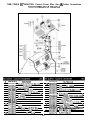
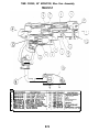
TIME CRISIS 50” MONITOR, Pedal Assembly w/Harness -
Pedal Assembly, Side View
1
96-0145-00
-
TCIO-04716.00
Btackel.
2
TC40-04666-00
Decal, feda/
3
VGZO-0288S20
ScrewBtn-Hd..Tm~~d.#10-24x1-1/~
4
VGZO-049X-16
5
VGZO-02863-05
R
TC%04730-00 Hamess.Gun
7
8
96-0149-00
43~0127-00
9 43-1013-00
1 0 43-0175-00
11
12
43-0324-00
96-0134-00
' 3 43-0425-00
14 96-0153-00
15
96m0:40-CO
I" 4%Oi75-00
1 6 43-3066-00
Foal Pedal
/nslruclfon
X10, Black, Oxide
& P edal Exlenston,
Hamess.Glin@nvetoGun&Pedal.5~
.TleHolder
GTlo-02231-00
VGZO-04969-W
~-W~reTle
Nut, Kep.M4.
1
20
96-0136-00
TC80-04671.05
Sw~lch.Plungef
1
1
21
96-0150-00
TC80-04671.07
Plunger,RubberStOP.
2
13
43-0426-00
VG20-04971.12
SURV,F&id.Ta~To?~%Mf~x12Chrare~ ‘
%0x 4
~scrxetHd,T~~~,ph1l1~.~~6.Biic~
Washer, Spilt-Lock,
X50-04729-O'LGT26-02439-00
4
14
96-0153-00
8
71
96-0138-00
50' Monlt3i
1
Mom’ai
1
1
Sleel,ZlnC
Washer.Lock.ExfemalToalh.4.SII.Z1nc
Front Cover
1
1
VG20.04971.12
TCG04671.01
~.~H4Tor~TmpPil,~~~lZ,Chr~PI
Rubber,Bumper
4
1
TC80-04671.02
Brackel.Swlch
Mounting
1
Nut. Keo.M4
Sleel.Zlnc
2
1 8 96-0148-00
VG20-G4969-04
-TCaO-04672-03
19 96-0135-00
1 0 43-0175-00
TC80-04672-04
VGZO-0496900
1 6 43-0066-00
VG20~04969~04
Washer Flal,M4
Actuator
andSwltch
23
1
VGZO-04970.00
TClO-04813-00
VGZO-04969.00
rctw-O~UT-00
Plunger Housing
Nut,Kep.ML
Steel.Ztnc
1
Washer fiat, I.44
4
24 43-0197-00
2 5 43-0428-00
VGZO-04971-12
GTZO-02257.00
Wasner.Flat.
M3.Sleel.ZlnC
5
5
16
43-0499-00
GTZO-02258-00
Washer.Sollt-Lock.M3,Steel,ZlflC
5
960141-00
TCBO-04671.08
Sprmg.Compresstan
Sprlng.Campression
1
TC80-04671-09
TC80-04671-10
Screw. Pan-Hd. Phillps.M3
Plale.Sprmg
Mount!ng
43.0424.ti
43-0175-00
YG20-04972.14
VG20.04969-00
Screw, Flat-Hd. PhIlips.
Nut.Kep,
M4,Steel,Zinc
31
96-0142-00
TC80-04691.13
Flo~r.PlaleAssembly
43-0175-00
VGZO:04969.00
Nut,Kep.M4.Steel.Z1nC
35
36
96-0137-00
43-3427-00
VGZO-04973.06
X80-04671-14
TC80.04671.11
TCBO-046%12
1
M5 x 14, SII.Zn
2
2
1
1
Screw.Truss-Hd.,Phil!ps.U5
Pivot Assembly
Plale,Swllch
Rlvet,M3
Y 16, SII,Zmc
Plunger
30
10
33 43-0425-00
3 4 96-0144-00
6..I ' 1
1
3
Spacer.BumperPad
--10
4
1
Tlper
Pad
TCEO-04671-06
28 96-0147-00
~2 9 96-0139-00
1
Rubber,Bul
Bumoer
96-0143-00
27
2
Assemby
TCBO-04671.01
TC80-04671-06
x6 6lk Ox
3
1
Actuator
-__
4
TIME CRISIS 50” MONITOR, PCB Set Assembly
TCOS-04786-00
WARNING: DO NOT separate
board set.
1
CYO6-03939M
Card cage
1
14
A203-04571-W
Mother PC6 Assembly (8646960602)
2
3
V620-02896-36
VGZO-02862.04
Screw Pan-Hd,Ph~lipr,18-32x2-1/~.SI1.Zn
Washer. Split-Lock. 18. SW Zinc
4
4
15
16
TC03-04845-W
TC03-04847-W
CPU(6)PCEAssembly(BM69626OO~
4
VGZO-02864~4
4
17
TCO%l3849-W
5
cY06-03910ul
Washer, Flat ia. Steel Zinc
CardCageCaver
I
la
VG2@03071-04
6
7
VGZO-04267-01
'VG06-03595-K
19
&dCage Slide
1
000364821-w
TC03.04846-W
a
9
CY50-04117.03
GT55-02248-K
Ribbon Cable loi adjacentPC3s
Fan Gr!ll
2
1
10
11
VG55-00060-K
VGZO-04712-0i)
Fan.Ax1al.I15VAC
I
12
13
VG2o-o2a"6-*3
VGZO-0X54-04
Saw &n-Hd.Ph~lips
#a-32 x2-112
'Washer Flal,ia.Steai.
Zinc
4mm Dla x6 mm Lg. TAS-bd
vutw~.a-32
PhIlIps Screw 12 -
c 112
20
21
4
Sd Zn 4
4
8-12
TC03-04848-00
MPM
V159Gun
(F)PCBAssembly(24479656)
Po1ntPCBAssemMy(2447960157,
- StandoH. PC6 hllnlalure Nylon
OSPPCBAssembly(8646960302)
M ROM PCBAssembly(24479654)
Video(B) PCBAssembly
(8646961200)
Aud~o,4r!p2CbannelPC8A%y(8&17~~
hI
22
TC03-04a51-oC
--23
TC50-04723-M)
Harness. Audio.
24
25
TCo31l4850-00
TC50-04952-W
~o~ntPCBAssembly(2447Q721o'
Harness GunPoslbonloJo&i
50' Mon~lor
-~- --
TIME CRISIS 50” MONITOR, List of Harness Assemblies
1
PHI SUPPlY
-~ .-~
+'8hws. SJT.6Ft.w/Moldd Plug 1
2
cw-03998.00
Harness. POW CGrd.Alqht
3
~251 owe-a0
PoverCoid.3Cand.
4
Tc50.0472oda
Harness
13
HarneSs
TCM-04914-aa
1
spearer. 50' hmlfOl
1
Fltolescenl
-
-.
16
EJ-a4124da
Hainess. DC Pow31 5o'Monltor
1
17
18
Tc50~041350a
Tc5sou32iIa
H61"W
1
19
Tcw-04725-00
Harness. CO," oooi B seruce PM 5c Monitor
20
m&04126-00
21
CY5uO371
Harnesr.Co"Ooor~ens,o"
Har"ess.:eNlce
Panel
22
TC5o-04727ilO
23
TC%-U4728-00
24
25
TC50-114733.00
TC5M)4734-W
26
21
TC50~4916-CC
RV5&04359W
AC Input (24vJ. 50' MOnliOr
Hil,"P.sS.24YPower,50'MonItor
i-00
1
g sewz Pane!.w
Harness. RGB 10-. NTSC PCB.5o'Monitor
Harness. CPU 10 Gun Dwe PCB. 5W Monilar
VGIO-04681-00
Plate.
VG20-02903-10
Screw.Pan-Hd,
Power
Harners.B
1
1
1
Fan
3
VG20-02700-05
4
VG52-03584-10
5
VGQ-03365-00
Fuse
6
VG44-02644-78
label, Fuse Va’alue,
1
AC
Philips.YExW Sleel, Zn
Holder.
Panel
1
1
Mount
1
7 Amo, ZOV, S l o wBlow
vc44-IwR.5l-00
Label Fuse Redacement
1
s
VG53-04683-00
Swlth.Rocker.DPST(ONIOFi)
1
3
VG95-02122-02
Stra~nRel~ef,PowerCard(Heyco,7i(-2)
10
CY50-03998-00
Harness, Power
11
VG51-01232-06
Power Card.3 Cond..#i
1
Cord, RIPower
Awa.UT.
Plug (101
70 EMI
1
7
w/Molded
0
4
Kepnut.Hex.10
-24. Steel. Zinc
-___
Fuse, 7 Amp, 25OV.Siow
Blow
1
Supply
6 Ft.
1
replacement use only)
NOTE: Item 11 is notpartof
Power Plate Assen lbly.
TIME CRISIS 50” MONITOR, Service Panel Assembly
DDO5-04768-00
1
VGiO-04684-00
2
VG20-02896-06
___:
IXR-07057-00
1
Brackel. Sawilce Panel
scIRN.P~~..phlllgs.RclBd.x8x318.,sII,~nc
Swltch.M~n~.?ush
iSerw?I
4
VGW02702-01
Label. 'SEWCE
5
GT53-00756.00
Tooole
6
VG44-02702-00
Label;TEST
Swttch.
7
VG53-02094-00
Cam Meler
R
VG7fl-07854-06
~&rew.
9
w'o-03717-00
Harness,
2
1
SPST (Test1
1
I
Pan-Hd. Phllios.4-40x316'
Seiv~ce
S:I, Zn 2
Panel
B-13
1
1
1
0005-04764-00
7
1
I
tlarnesa. EMI OUl. M' Manllor
Harness. Mm 50' Monllor
-.
Harness. RGE.Mm PCE f0 Video Amp
TIME CRISIS 50” MONITOR, Power Plate (AC) Assembly
1
1
MO"i,Ol
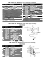
TIME CRISIS, 50” MONITOR, Blue Gun Assembly
PEO3-03141-01
?iQ
1.
7
3.
4.
2.
PB900U136al
6.
PB10-@4669ao
7.
PB10-04.57MO
3.
PBOY-29Wl
9.
PBOY-29&20
-L
TRlGGER.BLUE
BRACKET,SOLEP~OID
PBo9-29u67
PB95-@4942M)
BACKSPRING
B-14
name0
UUnE ‘CRUBUSTM
c c
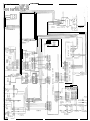
APPENDIX C:
50 INCH
WIRING DIAGRAM
Operator’s Manual
-~
WVU9Vla 3NltllM
Lo-z68Po-oS31
96/62/L axva 9 :mtl
llVkUA0
,,05 SlSlkl3 3Wll
--____-
I
E3d
olanv
II