1
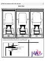
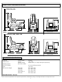
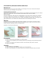
COLLECTION
OWNER'S MANUAL
pedicure
spas
by
Owner’s Manual
Standard Whirlpool Jet
SANIJET® Pipeless (Optional)
PETRA
PETRA
PETRA
PETRA
PETRA
PETRA
PETRA
PETRA
PETRA
PETRA
700
500
450
350R** or V***
300
700-S*
500-S
450-S
350R** or V***-S
300-S
S*=SANIJET® Pipeless
R**=Roller Massage
V***=Vibration Massage
Table of Contents
Introduction & Safety Standards
3
Important Considerations
4
Identifying Parts & Description (For Petra 700 & 500)
5
Massage System (For Petra 450, 350R, 350V & 300)
6
Chair Assembly (For Petra 700&500)
7
Chair Assemb ly (For Petra 450, 350R, 350V & 300)
8
Specifications (All Petra Collections)
9
Testing & Cleaning
10
Maintenance for Pipeless S-type Pedicure Spa (SANIJET® )
11, 12
Maintenance for Standard Pedicure Spa (Whirlpool Pump)
13, 14
Optional Discharge Pump installation guide
15
Lubrication (For Petra 700 & 500 Series)
16
Warranty Statement
17
2
Introduction
Thank you for purchasing the PETRA Whirlpool Pedicure Spa. This finest Whirlpool Pedicure Spa has
been developed by J&A USA, Inc. to operate dependably for many years when used properly. Please
take time to read this entire manual thoroughly before installation and use.
PLEASE READ AND FOLLOW INSTRUCTIONS CAREFULLY!
Important Precautions
J&A USA requires that you contact your local, qualified electrician and plumber to install your PETRA
Whirlpool Pedicure Spa. It cannot operate efficiently or safely unless it is provided with adequate
electrical power, sufficient water pressure, proper water temperature and required drain facilities.
Information on these important subjects contained in this manual. We urge you to read it carefully
to make sure these requirements are met.
Precautions
1 Excessive water temperature is dangerous and should be checked before use. Maximum water
temperature should not exceed 100 deg. F. (38 deg. C.).
2 Always enter and exit the Whirlpool Pedicure Spa slowly and carefully.
3 Never bring and/or operate any electrical devices into or near the Whirlpool Pedicure Spa.
4 Do not stand in the whirlpool tub!
5 This Whirlpool Pedicure Spa has a weight capacity of 250lb.
WARNING
Do Not use if you are diabetic, have poor blood circulation, or if any area of your
feet or legs are inflamed or have open wounds. Consult a physician before using if
you have any kind of fungal infection, swelling, fracture, or persistent pain.
Massage should be pleasant and comfortable.
IF YOU EXPERIENCE PAIN OR DISCOMFORT, DISCONTINUE USE IMMEDIATELY AND
CONSULT A PHYSICIAN.
This product in whole is in compliance with the applicable
UL LISTED standards and requirements for the US and Canada
by Underwriters Laboratories Inc.
Some of the components of this product are
also in compliance with the applicable
safety standards of the following:
3
Important Considerations
Please read the following instructions thoroughly
Inspection
Please take time to inspect each pedicure spa shipment thoroughly for damages immediately upon
delivery. If damages are found, it is very important to notify the freight driver and indicate extent of
the damages on the bill of lading. If you fail to do so, J&A USA will not be responsible for the
damages and may not be able to make appropriate claims to the freight carrier. Any damage claims
must be filed directly by receiver to the freight carrier.
Electrical Service
Each Foot spa must have its own dedicated 115V, 60 Hz, 15 Amp GFCI protected grounded circuit.
Water Supply
Water supply to the PETRA pedicure spa should consist of a system that will provide both adequate
water pressure and water temperature. All plumbing connections must conform to local codes.
Water Pressure
Normal water pressure of 30 to 120 P.S.I. is required to correctly fill the tub to the proper level.
Back Flow Prevention Device
- For following states: AZ, CA, IL, MN, NE, NV, OR, TX, WA, and WI;
All PETRA pedicure spa are equipped with factory installed Dual Check Back Flow Preventer.
Specification:
Tested and certified to meet ANSI/ASSE standard 1024. CSA certified to standard No.B64.6
Pressure / Temperature
Maximum pressure: 150 psi (10 bars)
Minimum pressure: 10 psi (69kPa)
Working temperature: 33F to 140F constant; intermittent to 180F
(0.6C to 60C sustained; intermittent to 82.2C)
Maximum recommended flow: 15 gpm (571pm)
-For all other states:
As an option, the Dual Check Back Flow Preventer will be factory installed.
* Inquire with governing authorities for local installation requirements.
Drain Facilities
Connect the Foot spa drain to meet local plumbing codes.
Please refer to the installation drawings on pages 9-10.
Foot spa is recommended securely fastened to the floor
Fasten the Foot spa with at least two fasteners.
Installation Summary
The installation must comply with local, state, and federal building, plumbing and electrical codes,
where applicable. A licensed plumber should complete the plumbing of the pedicure spa.
Note: Failure to comply with federal, state or local codes and ordinances will result in warranty being
null and void.
4
PETRA 700 & 500
IDENTIFYING PARTS
20
19
1
A
STOP
15
FORWARD
BACKWARD
B
KNEAD
TAP
2
UP
DOWN
AUTO
CONTINUE/REPEAT
3
THIGHMASSAGE
UP
MASSAGEWHEELS
4
J&A
DOWN
5
16
6
7
8
9
17
10
11
13
12
18
14
Standard Whirlpool Jet
SANIJET-Pipeless
PARTS
1 - PILLOW COVER
11 - SANIJET PUMP IMPELLER
2 - BACK REST
12 - OVERFLOW WASTE KNOB
3 - ARM REST
13 - POP-UP DRAIN STOPPER
4 - MATCHING ARM TRAY (OPTIONAL)
14 - LIGHT COVER
5 - SEAT CUSHION
15 - BACK PANEL
6 - SHOWER SPRAYER
16 - ARM REST LEVER
7 - ADJUSTABLE FOOT CUSHION
17 - BASE (SHELL)
8 - ON/OFF WHIRLPOOL BUTTON
18 - WHIRLPOOL JET
9 - OPTIONAL ON/OFF BUTTON (LIGHT or DISCHARGE PUMP)
19 - MASSAGE REMOTE CONTROL
10 - FAUCET
20 - SLIDE / RECLINE REMOTE CONTROL
Due to continuous improvements on all our products; specifications, characteristics, packing, colors, designs are subject to change without notice
5
PETRA 450, 350R, 350V & 300
MASSAGE SYSTEM
PETRA 300
PETRA 450
Pacific spa
J &A
J&A USA Inc.
VIBRATION
VIBRATION
TRANSFORMER
MODEL:GRA 1215
INPUT: AC 120V, 60Hz
OUTPUT: DC 12V, 1.5A
TRANSFORMER
MODEL: GRA 1215
INPUT: AC 120V, 60Hz
OUTPUT: DC 12V, 1.5A
PETRA 350 V
PETRA 350 R
TIMER
ROLLER
HEC
BACK
VIB
WAIST
SEAT
SPD
SEL
Pacific
Spa
AUTO
ByJ&AUSA
ROLLER MASSAGE
&
VIBRATION
VIBRATION
TRANSFORMER
MODEL: AD-57241200
INPUT: 120V, AC 60Hz
OUTPUT: 24V, DC 1.2A
TRANSFORMER
MODEL: MKD-57121500
INPUT: 120V, AC 60Hz
OUTPUT: 12V, DC 1.5A
Due to continuous improvements on all our products; specifications, characteristics, packing, colors, designs are subject to change without notice
6
PETRA 700 & 500 SERIES CHAIR ASSEMBLY
PETRA 700
IMPORTANT ASSEMBLY INSTALLATION
STOP
KNEAD
PRIOR TO USE
TAP
AUTO
A
8
FORWARD
CONTINUE/REPEAT
BACKWARD
B
THIGHMASSAGE
UP
UP
DOWN
MASSAGEWHEELS
J&A
DOWN
BEFORE ASSEMBLY
HOT
AFTER ASSEMBLY
8
COLD
1 2
4
3
5
1) LIGHT BOX POWER CORD
2) SLIDER / RECLINER POWER CORD
3) SANIJET CONTROL BOX POWER CORD
4) CHAIR MASSAGE POWER CORD
5) HITCH PIN CLIP
6) RECLINING PISTON
7) CLEVIS PIN
8) SUPPORT ARM BRACKET
7
6
CHAIR ASSEMBLY FOR PETRA 700 & 500 SERIES
1) REMOVE HITCH PIN AND CLEVIS PIN FROM RECLINING PISTON
2) LIFT THE CHAIR AND PLACE THE RECLINING PISTON ON
SUPPORT ARM BRACKET
3) INSERT CLEVIS PIN
4) SECURE WITH HITCH PIN CLIP
PETRA 500 WITH PIPELESS SANIJET
PETRA 500 WITH WHIRLPOOL JET
STOP
KNEAD
STOP
KNEAD
TAP
TAP
AUTO
AUTO
A
8
FORWARD
CONTINUE/REPEAT
B
THIGHMASSAGE
UP
UP
A
8
BACKWARD
1 2
3
UP
UP
MASSAGEWHEELS
J&A
DOWN
HOT
HOT
COLD
COLD
4
1 2
1) LIGHT BOX POWER CORD
2) SLIDER / RECLINER POWER CORD
3) SANIJET CONTROL BOX POWER CORD
4) CHAIR MASSAGE POWER CORD
3
1) WHIRLPOOL PUMP POWER CORD
2) SLIDER / RECLINER POWER CORD
3) LIGHT BOX POWER CORD
4) CHAIR MASSAGE POWER CORD
7
BACKWARD
B
THIGHMASSAGE
DOWN
MASSAGEWHEELS
J&A
FORWARD
CONTINUE/REPEAT
4
DOWN
DOWN
PETRA Chair Assembly for 450, 350R, 350V, 300
Rear View
PETRA 300
PETRA 450
PETRA 350R & 350V
CHANNEL FRAME
HOT
HOT
HOT
COLD
COLD
COLD
1) REMOVE THE LOCK NUT FROM THE BOLTS
2) ALIGN FOUR BOLTS WITH FOUR HOLES ON THE CHANNEL FRAME
3) TIGHTEN EACH LOCK NUTS TO SECURE THE CHAIR TO THE BASE
Bolt
Channel Frame
Washer
Lock Nut
8
PETRA COLLECTION SPECIFICATIONS
PETRA 700 & 500
55
25
18
19
18
2.5
43
24
8 3/4
6 3/4
27
28
57
41
WALL
HOT & COLD 0.5 inches
Fittings included
PETRA 450, 350R, 350V & 300
48
24
17
18
17
1.5
43
24
8 3/4
6 3/4
27
28
57
44
HOT & COLD 0.5 inches
Fittings included
Petra Collection Specifications
Capacity
Power Source
Plumbing Source
Hot & Cold Water
Drain
Dimension & Weight
All Petra Series
SaniJet
Whirlpool Pump
Hot & Cold Water
Petra 700
Petra 500
Petra 450
Petra 350R or V
Petra 300
5 gallons
115v, 60Hz
0.5HP, 115VAC, 5.5 Amp, 60Hz (GFCI protected)
0.5 inches (Fitting Included)
1.5 inches
57L x 28W x 55H
57L x 28W x 54H
57L x 28W x 48H
57L x 28W x 51H
57L x 28W x 48H
TOTAL AMPS PER SPA : 10.6 Amp
Due to continuous improvements on all our products; specifications, characteristics, packing, colors, designs are subject to change without notice
9
Plumbing Connections
All plumbing connections should be made by a qualified, licensed plumber in accordance with local
plumbing and building codes.
Hot and Cold Water Supply Lines
Connect 1/2” ID supply tubes to a fresh water source. Shut-off valves should be utilized.
Electrical Connections
The Foot spa must be plugged into a GFCI protected outlet, installed by a licensed electrician.
Testing the Foot spa
Clean the tub and fill with water to the wave-mark (water level) on the wall of the tub.
When the tub is filled with water, turn the switch on the front of the pedicure spa to activate the
whirlpool pump. Water should be coming out of the jets and the Air Bleed spout. Check for whirlpool
leaks. After checking under the tub for leaks, use the same switch to turn the whirlpool pump off
and drain the tub basin by opening the overflow/waste control handle and turning on the Power
Drain Pump if installed.
Cleaning and Care of Your Foot spa
Between Each Customer
• Drain all water and remove debris from the pedicure spa.
• Clean the surfaces and walls of the Foot spa with soap or detergent and rinse with clean, clear
water
• Disinfect with an EPA-registered disinfectant.
• Wipe out with a clean towel.
Flushing of the Whirlpool System
Caution: J&A USA requires that the pedicure spa be thoroughly cleaned after every 10th pedicure
and after the last pedicure of the day. It is extremely important to flush the whirlpool system of
the Foot spa to prevent harmful bacteria from growing and to prolong the life of your pedicure spa.
• Remove the Suction Fitting Cover with a phillips screwdriver
• Scrub the suction cover with a chlorine bleach solution of 1 (one) teaspoon of 5% chlorine bleach
to 1 gallon of water, or
• Totally immerse the suction Fitting cover in an EPA-registered disinfectant and scrub.
• Replace the Suction Fitting Cover with a screwdriver. Do not over tighten the mounting screw.
• Do not run the pedicure spa whirlpool jets without the Suction Fitting Cover in place.
• Fill the tub basin near the wave mark on the rear wall with hot water.
• Turn the whirlpool jets on.
• Add 3 (three) teaspoons of low foaming “crystal” dishwasher detergent and 2 (two) ounces of
household bleach to the tub basin.
• Run whirlpool for 10-15 minutes and drain the tub basin.
• Fill the tub basin near the wave mark on the rear wall with cold water.
• Run the whirlpool jets for 5 minutes and drain the tub basin.
• Clean the pedicure spa with a soft cloth and a mild detergent.
Weekly Disinfecting Procedure of the Whirlpool System
• After following the outlined procedures for daily cleaning, fill the pedicure spa tub with hot water
and 4 (four) teaspoons of 5% bleach solution.
• Circulate the solution through the whirlpool system for 5-10 minutes.
• Let the solution sit overnight (at least 6-10 hours).
• The following morning (before the first customer) run the foot spa for 5 minutes and drain.
• Follow the procedure “Flushing of the Whirlpool System”.
10
FOR SANIJET® -PIPELESS SYSTEM USERS ONLY
Maintenance
Keep the screen of the jet inlet free of debris, any blockage of the screen reduces the whirlpool
action and may cause damage to the jet motor.
Cleaning Pipeless Jet System
Remove the jet assembly from its casing: Rotate the jet assembly counterclockwise and pull outward.
Remove the impeller cap: rotate the impeller cap clockwise (OFF) and life outward.
Remove impeller.
Clean the components. After each jet is disassembled, the jet parts and jet casings can be cleaned
by hand. Jet parts may be cleaned in your dishwasher by placing them in the top rack away from
any heating element. Excessive heat (over 170i/EF) can damage the plastic parts. Jet casing can be
easily cleaned with a non-abrasive anti-bacterial cleaner when cleaning the tub shell.
Warning
DO NOT use if you are diabetic, have poor blood circulation, or if any area of your feet or leg is
inflamed or has open wound. Please consult your physician before using, if you have any kind of
fungal infection/s, swelling, fracture or persistent pain.
Assembly of the jet and maintenance
Disassembly
1) Prior to removing the jet assembly, turn off the power
2) Remove the jet assembly from its casing: Rotate the jet assembly counterclockwise and pull
outward.
3) Remove the impeller cap: Rotate the impeller cap clockwise (OFF) and lift outward.
4) Remove the impeller
Assembly
1) Place impeller on a jet assembly
2) Place the impeller cap: Rotate the impeller cap counterclockwise.
3) Place the jet assembly to its casing: Rotate the jet assembly clockwise and push inward.
11
Caution
To reduce the potential risk of fire, electrical shock, or injury to persons:
1) All electrical wiring (both installation & repair) must be done by a licensed electrician and in
accordance with local and state ordinances.
2) No modifications, additions or deletions should be made to the pump, without factory
approval.
3) Before stating motor, fill up the tub with water to level recommended by whirlpool
manufacturer. Never run pump dry!
4) Do not relocate pump without prior approval from factory.
Warning
To reduce the risk of injury, do not permit children to use this product unless they are closely
supervised at all times.
To reduce the risk of electric shock, replace damage cord immediately. And do not use extension
cord to connect unit to electric supply; provide a properly located outlet.
TROUBLESHOOTING GUIDE
SYMTOMS
Pump will not turn on
PROBABLE CAUSES
No power to motor
Pump runs slow
Pump not wired same as
voltage supplied
RECOMMENDED ACTION
Check switch, fuse or breaker, also
connection from motor to switch
Check pump to connect voltage
12
FOR STANDARD WHIRLPOOL SYSTEM USERS ONLY
Maintenance
Keep the screen of the suction inlet free of debris, any blockage of the screen reduces the whirlpool
action and may cause damage to the whirlpool pump motor.
Cleaning/ Flushing the inner whirlpool system
Fill up with warm water up to proper level.
Apply 3 tsp of low foaming dish washing detergent, 1 tsp of the regular bleach into the tub.
Start the whirlpool for 5 min and let it still for 5 min and run again for two minutes.
Drain out the water and fill up again with warm water.
Let it run for 5 minutes
Drain out the water.
Wipe dry with soft cloth.
Warning
DO NOT use if you are diabetic, have poor blood circulation, or if any area of your feet or leg is
inflamed or has open wound/s. Please consult your physician before using, if you have any kind of
fungal infection/s, swelling, fracture or persistent pain.
Assembly of the jet and maintenance
JET VENTURI
SLEEVE
ADJUSTABLE CARTIDGE
JET FACE
Assembly
1) With jet VENTURI and jet body in position, insert the cartridge into the body and lightly press
the jet face until the face clicks into the position.
2) Use finger to rotate the eyeball into position. If the assembly is seated, the eyeball will stay
in the correct position.
Disassembly
Press the eyeball inwards with your thumb. The eyeball will move freely when spring is compressed.
Using the fingers, grasp the edge of the jet and pry the face the body. It will snap out and clean
thoroughly, in jet, body, and cartridge for good maintenance as well as prevention from build up.
13
CAUTION
To reduce the potential risk of fire, electrical shock, or injury to persons:
1) All electrical wiring (both installation & repair) must be done by a licensed electrician and in accordance with local and state ordinances.
2) No modifications, additions or deletions should be made to the pump, without factory approval.
3) Before starting motor, fill tub with water to level recommended by whirlpool manufacturer. Never run pump dry!
4) Motors have a built-in automatic reset over load protector that guards against damage from mechanical or electrical problems such as
low voltage, locked pump or similar abnormal conditions. Remember, if the timer device is still on, these motors will restart
automatically - as soon as they cool down.
5) Do not relocate pump without prior approval from factory.
WARNING
-- To reduce the risk of injury, do not permit children to use this product unless they are closely supervised at all times.
-- To reduce the risk of electric shock, replace damage cord immediately. And Do not use extension cord to connect unit to electric
supply,; provide a properly located outlet.
TROUBLE SHOOTING GUIDE
SYMPTOMS
PROBABLE CAUSES
Pump will not turn on
No power to motor
Pump runs slow.
RECOMMENDED ACTION
Check switch and fuse or breaker, also connection from
motor To switch.
Pump not wired same as voltage supplied Check pump to correct voltage.
Something stuck in impeller.
Wire not tight..
Pump jammed.
Take pump apart and clean impeller( as shown below).
Check terminals.
Remove dust cap and rotate motor shaft with screwdriver.
If unable to turn, send in for repair.
Noisy pump
Something in the pump.
Take pump apart and remove debris.
Pump leaks.
Bad bearing.
Hose clamps or union loose.
Bolts holding tank loose.
Leak around shaft from worn seal.
Pump creeps.
Replace Bearing.
Tighten.
Tighten
Replace shaft seal.
Secure pump to floor.
Air from jets getting in suction
Direct directional flow fitting away from suction fitting.
Air lock.
Turn pump on, wait 10 seconds. Turn pump off.
Repeat up to 10 times. If airlock is not cure, try turn tee
union
#12) as shown in clock-wise and tighten back.(Do not turn
all
The way)
Pump Humms.
Pump Humms but
Will not turn.
Pump cavitates.
Pump runs but
No jet action.
.
9
PUMP PARTS LIST
ITEM
PARTS#
DESCRIPTION
1
2
3
WWVF
WWIMP
UPUFO/R
FRONT VOLUTE
IMPELLER
UNION O RING
4
5
6
7
8
9
10
10
12
UPUFM
UPUFF
PPSSFSEAL
PPWWVB
PPWWCORD
MPASHU506
PPWWVO/R
UPUFNUT
UNUTEE
UNION MALE 1 1/2"
UNION FEMALE 1 1/2"
SEAL ASSEMBLY
VOLUTE BACK
POWER CORD
AIR SWITCH
VOLUTE O RING
UNION NUT 1 1/2"
UNION TEE 1 1/2 X 1 X 1”
12
11
7
5
4
8
3
6
10
2
1
14
Discharge Pump Installation (Optional)
POWER CORD
ON/OFF DISCHARGE SWITCH
MUST BE PLACED HIGHER THAN WATER LEVEL
CONVERTER BOX
AIR TUBING
WATER LEVEL
Tub
Outlet
Check Valve must be installed to prevent back flow
B
A
AIR VENT HOSE
ATTACHMENT PIPE
Main Drain Pipe
L-TRAP
DISCHARGE PUMP
To prevent the possible air lock, B has to higher than A
- Outlet from drain pump must be placed
on top of the main drain pipe
- Do not use flexible pipe for drain
FAQ
1) Pump hums but does not drain the water out
- Air Lock : Piping elevation must be above discharge pump outlet
so that air can be released
- Turn pump on, wait 5 seconds, turn pump off. Repeat 10 times. If the air is not repleased,
detach attachment pipe and re-attach
Quick Tip: Use a plunger to release the air lock
2) Pump does not turn on
- Check the power source
- Check if the air tubing is properly attached from the switch to the converter box
- Check attachment pipes throughly for debris
3) Noise when turn on
- Foreign object may be lodged - Disassemble and remove debris or particles
15
Lubrication
1) Turn off the main power
1) Open the screws (phillip+) or Open the zippers from the front of the chair
2) Apply lubrication onto circled area
Caution
Do not apply lubrication on dc-belt
BACK VIEW
FRONT VIEW
REMOVE SCREWS (PHILLIP)
TO OPEN THE PANEL
DC-PULLEY
DC-BELT GEAR PULLEY
UPPER SENSOR
IMPORTANT!!!
DC-MOTOR
GEAR BOX
LUBRICATE ON CIRCLED AREA
MACHINERY OIL RECOMMENDED
OIL RESERVOIR
LOWER SENSOR
MAIN SHAFT
MAIN ON/OPF POWER SWITCH
AC MOTOR
TRANSFORMER
PCB BOARD
FUSE
MAIN SHAFT
Zipper
When massage is not functional :
Always check your power source first
- check power cord
- check main on/off power switch
- check fuse/s
If problem persists, contact your local distributor, or manufacturer with your serial number
It is strongly recommended that main shaft be lubricated in a proper way at least once a month
to ensure smooth operation
16
J&A USA, INC. LIMITED WARRANTY STATEMENT
J&A Product: EPISODE, PETRA, TOEPIA, CLEO, PACIFIC SPA
J&A Accessories: Epi-Stool, Tri-Stool, __________
Duration of limited warranty: 1 year from date of purchase
Coverage on limited warranty: Parts & Labor
EXTENT OF LIMITED WARRANTY
J&A USA warrants that the J&A product and/or accessories specified above will be free from defects in materials and
workmanship for the duration specified above. Which duration begins on the date of purchase by the customer (salon,
spa). Customer is responsible for maintaining proof of date of purchase and manual booklet in order to initiate the
warranty, the customer must send J&A Warranty Card in the manual booklet. Read carefully and return to J&A within 15
days from the date of purchase.
If J&A receives notice of a defective product during the applicable warranty period, J&A shall either repair or replace the
defective parts at J&A’s option. Replacement product may be either new or equivalent in performance to new. If J&A is
unable to repair or replace, as applicable, a defective product covered by the J&A’s warranty, J&A shall, within a
reasonable time after being notified of the defect, replacement of equivalent purchased price for J&A product, accessories,
or supplies. J&A shall have no obligation to repair, replace, or refund until the verification process by J&A is completed.
J&A’s limited warranty is valid in US where the covered J&A product is distributed by J&A. additional warranty services,
may be available from any authorized J&A service facility where the product is distributed by J&A or by an authorized
importer.
J&A’s limited warranty cover only those defects which arise as a result of normal use of the product, and do not apply to
any:
• Improper or inadequate maintenance or modification
• Unauthorized modification or misuse
• Improper site preparation or maintenance
Any applicable warranty shall not apply to J&A that have been improper installation or plumbing, remanufactured,
refurbished, misused or tampered with in any way.
LIMITATION OF WARRANTY
TO THE EXTENT ALLOWED BY LOCAL LAW, NEITHER J&A NOR ITS THIRD PARTY SUPPLIERS MAKE ANY OTHER WARRANTY OR
CONDITION OF ANY KIND, WHETHER EXPRESS OR IMPLIED, WITH RESPECT TO THE J&A PRODUCTS, AND SPECIFICALLY DISCLAIM THE
IMPLIED WARRANTIES OR CONDITIONS OF MERCHANTABILITY, SATISFACTORY QUALITY, AND FITNESS FOR A PARTICULAR PURPOSE.
Some states or providences do not allow limitations on the duration of an implied warranty, so the above limitation or exclusion might not apply to you.
This warranty gives you specific legal rights that vary from state to state, or providence to providence.
LIMITATION OF LIABILITY
To the extent allowed by the local law, remedies provided in this warranty statement are the customer’s sole and exclusive remedies.
TO THE EXTENT ALLOWED BY LOCAL LAW, EXCEPT FOR THE OBLIGATIONS SPECIFICALLY SER FORTH IN THIS WARRANTY STATEMENT,
IN NO EVENT WILL J&A OR ITS THIRD PARTY SUPPLIERS BE LIABLE FOR DIRECT, INDIRECT, SPECIAL, INCIDENTAL, OR CONSEQUENTIAL
(INCLUDING LOST PROFIT) DAMAGES, WHETHER BASED ON CONTRACT, TORT, OR ANY OTHER LEGAL THEORY AND WHETHER ADVISED
OF THE POSSIBILITY OF SUCH DAMAGES.
OBTAINING TECHNICAL SUPPORT
Please, look for help in the following order:
1) See Trouble Shooting Guide located in the Manual
2) E-mail us; detailed description of your problem, if you have an internet access
3) Fax us ; detailed description of you problem, if you have a fax machine
4) Contact your local distributor and request an A/S report to be filed on your behalf
5) Contact J&A tech support by phone
Please have the following information ready:
1) Salon or Spa Name, Address, Telephone Number
2) Contact Name
3) Model Name, Serial number of the problem unit
4) Brief Description of the problem
J&A USA, INC
200 RODEO DRIVE, EDGEWOOD, NY 11717
PHONE: (631)243-3336
FAX: (631)243-3339
WEBSITE: WWW.JAUSAINC.COM
EMAIL:[email protected]
17
MULTI-COLOR LED SPA LIGHT
(Instruction for LED Bulb replacement)
WARNING: Rick of electric shock!!!,
Drain spa and disconnect power before attempting to open lens.
Multicolor LED spa lights allows the replacement of the lamp from the front.
It comes complete with a plastic insert tool for tightening, or un-tightening.
NOTE:
To change a bulb after installation,
follow the instruction engraved on the lamp replacement too.
Insert the two tabs of the insert tool into the two notches on
the front lens of the light assembly
(counter-clockwise to REMOVE; clockwise to INSTALL)
See figure 1.
INSERT TOOL
1. Remove lens with tool (provided)
2. Pull bulb straight out
3. Gently push in new bulb (important)
4. Assure O ring is in place
5. Replace lens with tool
6. Tighten to align tool with notch
Figure 1
Insert Tool
Front Lens
QMTX.E242637
Plumbing Accessories
See General Information for Plumbing Accessories
J & A USA INC
200 RODEO DR
EDGEWOOD, NY 11717 USA
E242637
Whirlpool pedicure spas, Models PS300, PS650LX, Episode, Episode-S Type, Toepia
EM, Cleo , Petra.
Last Updated on 2004-10-19
This page and all contents are Copyright © 2005 by Underwriters Laboratories Inc.®
The appearance of a company's name or product in this database does not in itself assure that products so
identified have been manufactured under UL's Follow-Up Service. Only those products bearing the UL
Mark should be considered to be Listed and covered under UL's Follow-Up Service. Always look for the
Mark on the product.
UL permits the reproduction of the material contained in the Online Certification Directory subject to the
following conditions: 1. The Guide Information, Designs and/or Listings (files) must be presented in their
entirety and in a non-misleading manner, without any manipulation of the data (or drawings). 2. The
statement "Reprinted from the Online Certifications Directory with permission from Underwriters
Laboratories Inc." must appear adjacent to the extracted material. In addition, the reprinted material must
include a copyright notice in the following format: "Copyright © 2005 Underwriters Laboratories Inc.® "