1
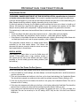
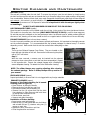
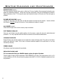
N IO AT TR ty I S ra n EG ar R /w T Y c om N A ir o . R R e nv A W SHERWOOD INDUSTRIES IS AN ENVIRONMENTALLY RESPONSIBLE COMPANY. THIS MANUAL IS PRINTED ON RECYCLED PAPER. PLEASE KEEP THESE INSTRUCTIONS FOR FUTURE REFERENCE PELLET STOVE Empress-1 FS OWNER’S MANUAL Contact your building or fire officials about restrictions and installation inspection requirements in your area. PLEASE READ THIS ENTIRE MANUAL BEFORE INSTALLATION AND USE OF THIS PELLET-BURNING ROOM HEATER. FAILURE TO FOLLOW THESE INSTRUCTIONS COULD RESULT IN PROPERTY DAMAGE, BODILY INJURY OR EVEN DEATH. 50-1266 Table of Contents Introduction........................................................................................3 Rating Label Location................................................................3 Pellet Quality............................................................................3 Important Safety Data...............................................................4 Safety Warnings And Recommendations.....................................4 Specifications......................................................................................6 Dimensions..............................................................................6 Operating Instructions..........................................................................7 Control Board Functions.............................................................7 Automatic Safety Features of Your Pellet Stove............................7 Operating Your Pellet Stove:......................................................7 Turning Your Pellet Stove Off:....................................................8 Slider/Damper Set-Up:..............................................................9 Guidelines For Fine-Tuning For Fuel Quality.................................9 Routine Cleaning and Maintenance......................................................10 Warranty...........................................................................................13 Installation Data Sheet.......................................................................14 2 Introduction * This manual is designed for the home owner in conjunction with the technical manual. * Rating Label Location: The rating label is located on the back of the hopper. Pellet Quality: Pellet quality is important, please read the following: Your enviro pellet stove has been designed to burn wood pellets only. Do not use any other type of fuel, as this will void any warranties stated in this manual. The performance of your pellet stove is greatly affected by the type and quality of wood pellets being burned. As the heat output of various quality wood pellets differs, so will the performance and heat output of the pellet stove. Caution: It is important to select and use only pellets that are dry and free of dirt or any impurities such as high salt content. Dirty fuel will adversely affect the operation and performance of the unit and will void the warranty. The Pellet Fuel Industries (P.F.I.) has established standards for wood pellet manufacturers. We recommend the use of pellets that meet or exceed these standards. Ask your dealer for a recommended pellet type. P.F.I. PELLET STANDARDS: Fines (fine particles)......1% maximum through a ⅛” screen Bulk Density..................40 pound per cubic foot minimum Size..............................¼” to 5/16” diameter ½ – 1½” long maximum Ash Content..................1% maximum (Premium grade) ..................3% maximum (Standard grade) Moisture Content...........8% maximum Heat Content.................approximately 8200 Btu per pound minimum ASH: The ash content of the fuel and operation of your stove will directly determine the frequency of cleaning. The use of high ash fuels may result in the stove needing to be cleaned daily. A low ash fuel may allow longer intervals between cleaning. CLINKERING: [clinkers are silica (sand) or other impurities in the fuel that will form a hard mass during the burning process]. This hard mass will block the air flow through the Burn Pot Liner and affect the performance of the stove. Any fuel, even approved types, may tend to clinker. Check the Burn-Pot Liner daily to ensure that the holes are not blocked with clinkers. If they become blocked, remove the liner (when the unit is cold) and clean/scrape the clinkers out. Clean the holes with a small pointed object if required. Refer to the section Routine Cleaning and Maintenance. PELLET FEED RATES: Due to different fuel densities and sizes, pellet feed rates may vary. This may require an adjustment to the slider damper setting or to the auger feed trim setting on low. Since Sherwood Industries Ltd. has no control over the quality of pellets that you use, we assume no liability for your choice in wood pellets. Store pellets at least 36” (1 m) away from the pellet stove. 3 Introduction Important Safety Data: Please read this entire Owner’s Manual before installing or operating your ENVIRO Pellet Stove. Failure to follow these instructions may result in property damage, bodily injury or even death. Contact your local building or fire official to obtain a permit and any information on installation restrictions and inspection requirements for your area. To prevent the possibility of a fire, ensure that the appliance is properly installed by adhering to the installation instructions. An ENVIRO dealer will be happy to assist you in obtaining information with regards to your local building codes and installation restrictions. Be sure to maintain the structural integrity of the home when passing a vent through walls, ceilings, or roofs. The stove’s exhaust system works with negative combustion chamber pressure and a slightly positive chimney pressure. It is very important to ensure that the exhaust system be sealed and airtight. The ash pan and viewing door must be locked securely for proper and safe operation of the pellet stove. Do not burn with insufficient combustion air. A periodic check is recommended to ensure proper combustion air is admitted to the combustion chamber. Setting the proper combustion air is achieved by adjusting the slider damper located on the left side of the stove. When installing the stove in a mobile home, it must be electrically grounded to the steel chassis of the home and bolted to the floor. Make sure that the structural integrity of the home is maintained and all construction meets local building codes. Minor soot or creosote may accumulate when the stove is operated under incorrect conditions such as an extremely rich burn (black tipped, lazy orange flames). If you have any questions with regard to your stove or the above-mentioned information, please feel free to contact your local dealer for further clarification and comments. Safety Warnings And Recommendations: Caution: Do not connect to any air distribution duct or system. Do not burn garbage or flammable fluids such as gasoline, naptha or engine oil. Unit hot while in operation. Keep children, clothing and furniture away. Contact may cause skin burns. FUEL: This pellet stove is designed and approved to only burn wood pellet fuel with up to 3% ash content. Dirty fuel will adversely affect the operation and performance of the unit and may void the warranty. Check with your dealer for fuel recommendations. THE USE OF CORDWOOD IS PROHIBITED BY LAW. SOOT: Operation of the stove with insufficient combustion air will result in the formation of soot which will collect on the glass, the heat exchanger, the exhaust vent system, and may stain the outside of the house. This is a dangerous situation and is inefficient. Frequently check your stove and adjust the slider/ damper as needed to ensure proper combustion. See: “Slider/Damper Setting”. CLEANING: There will be some build up of fly ash and small amounts of creosote in the exhaust. This will vary due to the ash content of the fuel used and the operation of the stove. It is advisable to inspect and clean the exhaust vent semi-annually or every two tons of pellets. 4 Introduction ASHES: Disposed ashes should be placed in a metal container with a tight fitting lid. The closed container of ashes should be on a non-combustible floor on the ground, well away from all combustible materials pending final disposal. If the ashes are disposed of by burial in soil or otherwise locally dispensed, they should be retained in the closed container until all cinders have been thoroughly cooled. ELECTRICAL: The use of a surge protected power bar is recommended. The unit must be grounded. The grounded electrical cord should be connected to a standard 120 volts, 60 hertz electrical outlet and also must be accessible. If this power cord should become damaged, a replacement power cord must be purchased from the manufacturer or a qualified ENVIRO dealer. Be careful that the electrical cord is not trapped under the appliance and that it is clear of any hot surfaces or sharp edges. This unit’s maximum power requirement is (4.1 Amps) 500 watts. GLASS: Do not abuse the glass by striking or slamming the door. Do not attempt to operate the stove with broken glass. The stove uses ceramic glass. Replacement glass must be purchased from an ENVIRO dealer. Do not attempt to open the door and clean the glass while the unit is in operation or if glass is hot. To clean the glass, use a soft cotton cloth and mild window cleaner, gas or wood stove glass cleaner, or take a damp paper towel and dip into the fly ash. This is a very mild abrasive and will not damage the glass. FLAMMABLE LIQUIDS: Never use gasoline, gasoline-type lantern fuel, kerosene, charcoal lighter fluid, or similar liquids to start or “freshen up” a fire in the heater. Keep all such liquids well away from the heater while it is in use. SMOKE DETECTOR: Smoke detectors should be installed and maintained in the structure when installing and operating a pellet burning appliance. OPERATION: The ash pan and door must be closed securely for proper and safe operation of the pellet stove. Also ensure all gaskets on the door are checked and replaced when necessary. KEEP ASH PAN FREE OF RAW FUEL. DO NOT PLACE UNBURNED OR NEW PELLET FUEL IN ASH PAN. A fire in the ash pan may occur. INSTALLATION: Be sure to maintain the structural integrity of your home when passing a vent through walls, ceilings, or roofs. It is recommended that the unit be secured into its position in order to avoid any displacement. DO NOT INSTALL A FLUE DAMPER IN THE EXHAUST VENTING SYSTEM OF THIS UNIT. DO NOT CONNECT THIS UNIT TO A CHIMNEY FLUE SERVING ANOTHER APPLIANCE. FRESH AIR: Outside Fresh Air connection is optional. Must be connected to all units installed in Mobile and “Air Tight Homes” (R2000) or where required by local codes. Consider all large air moving devices when installing your unit and provide room air accordingly. Limited air for combustion may result in poor performance, smoking and other side effects of poor combustion. If you have any questions with regards to your stove or the above-mentioned information, please feel free to contact your local dealer for further clarification and comments. Since Sherwood Industries Ltd. has no control over the installation of your stove, SHERWOOD INDUSTRIES LTD. grants no warranty implied or stated for the installation or maintenance of your stove. Therefore, Sherwood Industries Ltd. assumes no responsibility for any consequential damage(s). SAVE THIS INSTRUCTION MANUAL FOR FUTURE REFERENCE 5 Specifications Dimensions: 153/4" (400mm) 153/8" (390mm) 253/4" (653mm) 247/16" (621mm) 273/8" (695mm) 243/16" (614mm) Figure 1: Empress Dimensions. 6 Operating Instructions Control Board Functions: 1. AUGER LIGHT: This green light will flash in conjunction with the auger pulse. 2. MODE LIGHT: Responsible for signaling the state of the control board. When the light is flashing the stove is in an automatic start mode or the thermostat has control of the unit. When the light is solid, the Heat Level Setting can be altered. 3. THERMOSTAT SWITCH: Used to set the unit’s controls to one of three mode settings; manual, high/low, or auto/off. 4. FEED RATE TRIM BUTTON: Used to change the feed rate trims in ¼ second increments for all feed settings. When this button is pressed, all the light will light up on the Heat Output Indicator except for the one that shows the current setting; the default setting is the number 4 light. To adjust the setting hold the Feed Rate Trim button down and press the Heat Level up or down buttons to adjust the setting. 5. COMBUSTION BLOWER TRIM BUTTON: Used to change the Combustion Blower trims in 5 volt increments for all feed settings until it reaches line voltage. When this button is pressed, all the light will light up on the Heat Output Indicator except for the one that shows the current setting; the default setting is the number 2 light. To adjust the setting hold the Combustion Blower Trim button down and press the Heat Level up or down buttons to adjust the setting. 6. ON/OFF BUTTON: Used to turn the unit ON and OFF. 7. HEAT LEVEL ADJUSTMENT BUTTONS: When pressed, will change the heat level setting of the unit up or down. 8. HEAT OUTPUT INDICATOR: Shows the present heat output setting. Figure 2: Circuit Board Control Panel Decal. Automatic Safety Features of Your Pellet Stove: A. The stove will shut off when the fire goes out and the exhaust temperature drops below 120°F (49°C). B. The stove has a high temperature safety switch. If the temperature on the hopper reaches 200°F (93°C), the auger will automatically stop and the stove will shut down when the exhaust temperature cools #4 light flashes. Dealer will have to reset the sensor. If this happens, call your local dealer to reset the 200°F (93°C) high limit switch. ALSO FIND THE REASONS WHY THE UNIT OVERHEATED. C) The unit is equipped with a vacuum switch to monitor the venting; if it becomes blocked the vacuum switch will turn off the auger and the #2 light on the control board will flash. Operating Your Pellet Stove: PRE-BURN INSTRUCTIONS: The burn pot liner holes must be clear and the liner installed properly against the ignitor tube for proper operation. Check the hopper for enough pellets to start the unit. DO NOT OPERATE THE UNIT WITH THE DOOR OR ASH PAN OPEN. Note: The thermostat mode can be changed during normal operation. 7 Operating1 Instructions AUGER AUGER MANUAL MODE: MODE MODE 2 9 circuit board function is adjusted at the circuit board. All control of AUTO/OFF AUTO/OFF To START: Press the ON / OFF button. The stove will turn on. The HIGH/LOW HIGH/LOW 3 system light will flash. The Auger Light will flash with each pulse of the MANUAL MANUAL auger (the Auger Feed Rate is pre-programmed during start-up). The Heat Level Indicator will show the Heat Level 4that the stove will run at after start-up and can be adjusted but the change will not take affect Figure 3: ThermostatFEED Switch FEED RATE RATE in HEAT LEVEL HEAT LEVEL until the start has finished. 8 -up TRIM TRIM MANUAL position. If this is the first time the unit has been started or the unit has run out 5 of fuel, the auger will need to be primed. This can be done by restarting the unit five (5) minutes into its COMBUSTION COMBUSTION start-up or by putting a small hand full TRIM of pellets into the burnpot. BLOWER BLOWER TRIM To OPERATE: When a fire has been established, the System Light will turn solid (after approximately 10 6 7 - 15 minutes) and the Auger Light will continue to flash to the corresponding Heat Level setting. ROOM AIR ON/OFF ROOM AIR ON/OFF The convection blower (room air blower) will turn on. The speed of this blower controlled by the setting FAN ON/OFF FANis ON/OFF of the heat level output indicator. 1 AUGER AUGER HIGH/LOW MODE: (Requires a thermostat) INITIAL START-UP: See manual mode MODE MODE C-11625 C-11625above. 2 9 OPERATION: When the thermostat calls for heat (contacts are closed) AUTO/OFF AUTO/OFF the stove settings are adjustable as per Manual Mode. When the HIGH/LOW HIGH/LOW 3 thermostat contacts open, the HEAT LEVEL and Fans will drop down to MANUAL MANUAL the LOW setting until the thermostat contacts close again. *The LOW heat setting can be adjusted for different fuel4 qualities (see “Operating Instructions - Control Board Functions ”). The stove will come back to Figure 4: ThermostatFEED Switch FEED RATE RATE in 1 AUGER AUGER HEAT LEVEL HEAT LEVEL 8 TRIM TRIM the previous HEAT LEVEL setting when the thermostat contacts close HIGH/LOW position. again. 5 MODE MODE 2 9 COMBUSTION COMBUSTION AUTO/OFF MODE: (RequiresAUTO/OFF aBLOWER thermostat) TRIM BLOWER TRIM AUTO/OFF INITIAL START-UP: See manual HIGH/LOW mode above. HIGH/LOW 3 6 7 MANUAL MANUAL OPERATION: When the thermostat contacts close, the unit will light ROOMup AIR to temperature, ON/OFF the stove operates the same ROOM AIR ON/OFF automatically. Once FAN ON/OFF FAN ON/OFF 4 as in MANUAL. When the thermostat contacts open, the stove’s HEAT Figure 5: ThermostatFEED Switch FEED LOW RATE setting for 30 minutes. If the RATE in LEVEL and Fans will drop down to the HEAT LEVEL HEAT LEVEL 8 ON/OFF position. TRIM TRIM thermostat contacts close within the 30 minutes, the HEAT LEVEL will C-11625 C-11625 return to the previous MANUAL setting. If the5thermostat contacts remain open the stove automatically COMBUSTION COMBUSTION begins its shutdown routine. The ON / OFF button can be presses at any time the the stove will immediately BLOWER TRIM BLOWER TRIM shut down. The stove will re-light when the thermostat contacts close again. 6 7 Turning Your PROOM ellet Stove Off: AIR ON/OFF FAN ON/OFF ROOM AIR FAN ON/OFF ON/OFF • MANUAL and HI / LOW mode: To turn the unit OFF, simply press the ON / OFF button. This will stop the feed of pellets. The blowers will continue to operate and cool the stove down. When cool enough, the stove will turn off. • AUTO / OFF mode: To turn the unit C-11625 OFF, turn the thermostat down or off. NOTE: The unit will C-11625 run on low for three (3) minutes before it turns off. DO NOT unplug unit while Combustion fan is operating. This may lead to smoke escaping from the stove. 8 Operating Instructions Slider/Damper Set-Up: The Slider / Damper must be set at time of installation. A Qualified Service Technician or Installer must set the Slider Damper. This is used to regulate the airflow through the pellet stove. If the fire should happen to go out and the heat output indicator has been set on the lowest setting, the Slider Damper should be pushed in slightly, decreasing the air in the firebox. If, after long periods of burning, the fire builds up and overflows the burn pot or there is a build up of clinkers, this would be a sign that the pellet quality is poor, this requires more primary air, the slider damper must be pulled out to compensate. Pulling the slider damper out gives the fire more air. The easiest way to make sure that an efficient flame is achieved is to understand the characteristics of the fire. • A tall, lazy flame with dark orange tips requires more air – Open slider (pull out) slightly. • A short, brisk flame, like a blowtorch, has too much air – Close slider (push in) slightly. • If the flame is in the middle of these two characteristics with a bright yellow/orange, active flame with no black tips then the air is set for proper operation, refer to Figure 6. The combustion exhaust blower is a variable speed blower controlled by the heat output button. This blower will decrease the vacuum pressure inside the stove and as the heat output button is turned down. SPECIAL NOTES: Pellet quality is a major factor in how the Pellet stove will operate. If the pellets have a high moisture content or ash content the fire will be less efficient and has a higher possibility of the fire building up and creating clinkers (hard ash build-up). Figure 6: Efficient Flame. Guidelines For Fine-Tuning For Fuel Quality: Due to fuel quality the slider damper and control board trims may need to be fine-tuned. 1.If the unit builds up on all settings, the slider damper rod should be pulled out in small increments to give the unit more air. 2.If the unit has excesses ash build-up in the liner on the lower feed settings, the Combustion Blower Trim should be increased one setting at a time until the problem improves (Factory Setting is #2). 3.If the fire is going out on low because the airflow is too great, the Combustion Blower Trim can be lowered to the #1 setting. 4.If the stove has excesses ash build-up in the liner on the higher settings the Feed Rate Trim should be trimmed down a setting at a time until the problem improves (Factory setting is #4). 5.If you need more heat and the fuel has long pellets, the majority are over 1” (2.5cm) in length, the Feed Rate Trim can be moved up to the #5 setting. NOTE: Only do this if the fuel burns without building up. 9 Routine Cleaning and Maintenance The following list of components should be inspected and maintained routinely to ensure that the appliance is operating at its optimum and giving you excellent heat value: 2-3 Days / Weekly Burn Pot and Liner Ash Pan Inside Firebox Door Glass Heat exchanger tubes Ash pan and Door gaskets Door Latch Semi-annually or 2 Tons of Fuel Exhaust Vent Fresh air Intake Tube Blower Mechanisms Heat exchanger tubes Behind firebox liners All Hinges Post Season Clean-up TOOLS REQUIRED TO CLEAN UNIT • Torx T-20 Screwdriver • Brush • Soft Cloth • 5/16” Wrench or Socket • Vacuum with fine filter bag Burn Pot Liner Ignitor Air Intake Tube Burn Pot BURN POT AND LINER (2-3 days) Figure 7: Burn pot assembly. Cleaning of the burn pot and liner must only be done when stove is cold. To remove the burn pot and burn pot liner, open the door using the door handle provided (located on the right-hand side of the stove). Swing the door open. Lift the liner from the burn pot. Lift the burn pot from the firebox by gently lifting up the front of the burn pot, then sliding the assembly from the air intake tube and the ignitor cartridge. This is the ‘pot’ where the pellets are burned. Every two to three days (when the unit is cold), remove the burn-pot liner from the stove and inspected it to ensure proper air flow through the liner. Failure to keep the liner clean may cause a build up of fuel past the burn pot liner and up the drop tube. This will cause the auger to jam and may result in pellets burning in the drop tube and hopper. Using a metal scrapper, remove material that has accumulated or is clogging the liner’s holes. Then dispose of the scrapped ashes from the liner and from inside the burn-pot. Place the burn-pot back into the stove, making sure that the pipes are properly inserted into the burn pot. Place the liner back into the burn-pot, making sure that the ignitor hole in the liner is aligned with the ignitor tube. Pushing the liner up against the ignitor tube. If, after long periods of burning, the fire continually builds up and overflows the burn pot or there is a build up of clinkers, this is an indication that the pellet fuel quality is poor or the stove may need cleaning. Check the stove for ash build up (clean if required) and adjust the slider / damper to produce the proper clean combustion. DOOR LATCH (2-3 days) Check the door latch every time the door is opened or closed to ensure proper movement. DOOR GLASS CLEANING (When needed) Cleaning of the glass must only be done when stove is cold. Open the door by lifting the handle. The glass can be cleaned by wiping down the outside and inside of the glass with a dry soft cloth. If the glass has build up that can not be removed with only the cloth, clean the glass using paper towel and a gas appliance glass cleaner, this may be purchased through most dealers. If a gas appliance glass cleaner is not available, use a damp paper towel dipped in fly ash to clean the glass. After the glass has been cleaned use the dry soft cloth to wiping down the outside and inside of the glass. ASH PAN AND DOOR GASKETS (weekly) After extended use the gasketing may come loose. To repair this, glue the gasketing on using hightemperature fiberglass gasket glue available from your local ENVIRO dealer. This is important to maintain an airtight assembly. 10 Routine Cleaning and Maintenance ASH PAN (weekly) The ash pan is located under the ash shelf. To remove the ash pan, open the ash drawer by simply turning the latch and then pull the ash pan out towards the front. Dump the ashes into a metal container stored away from combustibles. Monitor the ash level every week. Remember that different pellet fuels will have different ash contents. Ash content is a good indication of fuel efficiency and quality. Refer to “Introduction - Safety Warnings And Recommendations” for disposal of ashes. It is important to latch the ash pan tightly when re-installing it. DO NOT PLACE UNBURNED OR RAW PELLET FUEL IN ASH PAN. HEAT EXCHANGER TUBES (weekly) Open the cast front and the rod is located under the unit top, in the center of the stove just above the door. This handle is to be pulled out a few times (ONLY WHEN THE UNIT IS COLD) in order to clean away any fly ash that may have collected on the heat exchanger tubes. As different types of pellets produce different amounts of ash, cleaning of the tubes should be done on a regular basis to enable the unit to run efficiently. EXHAUST PASSAGES (two to three times a season) In order to properly maintain your unit and ensure optimal performance, it is important to thoroughly vacuum out the exhaust passages. It is recommended that the exhaust passages be cleaned every 1-2 months depending on use. Make certain that the unit has cooled before attempting to clean. Step 1 There are two Exhaust Passage Cover Plates. They are located on the lower left and right sides of the unit. Remove the bolts securing the plates with a 5/16” hex socket. Step 2 - With the cover removed, a vacuum may be inserted into the exhaust passage to clean out any dust or ash that may have accumulated. Repeat on the opposite side. Inspect the exhaust passage with a flashlight to ensure adequate cleaning. Re-attach the Cover Plates after cleaning. NOTE: The slider/damper may require adjusting after cleaning the exhaust passage. Refer to Slider/Damper Set-up section of your manual. FRESH AIR INTAKE (season) Inspect periodically to be sure that it is not clogged with any foreign materials. EXHAUST PASSAGES (season) Removal of the firebox backing for bi-annual cleaning (refer to Figure 8): • Open the door by lifting the handle. • Remove the burn pot and burn pot liner. • Lubricate all screws with penetrating oil. • Remove the four (4) screws that hold the brick liner retainers in place. Remove side brick liners by sliding them forward then out. • Pull the center panel out. • Vacuum and clean thoroughly. Installation of firebox backing: • Insert center panel with backing. • Place the two (2) side panels back into the firebox and reinstall the two (2) retainers using two (2) screws on each side. • Replace the burn pot and burn pot liner • Close the glass door and secure. Figure 8: Firebox Components Removal. 11 Routine Cleaning and Maintenance EXHAUST VENT (season) This vent should be cleaned every year or after two (2) tons of pellets. We recommend contacting your dealer for professional cleaning. To clean the vent pipe, tap lightly on the pipe to dislodge any loose ash. Open the bottom of the “T” to dump the ash, then vacuum as much of the ash out of the vent pipe as possible. BLOWER MECHANISMS (season) Unplug the stove then open the right and left side panels to access the two blowers. Vacuum all dust from motors. DO NOT lubricate the motors. Check gaskets and replace if needed. ALL HINGES (season) Check all the hinges on the unit to ensure proper movement. POST SEASON CLEAN-UP Once you are finished using the pellet appliance for the season, unplug the stove for added electrical protection. It is very important that the stove be cleaned and serviced as stated above. CLEANING SURFACES Enamel finishes and painted surfaces can be wiped down with a soft damp cloth. The paint on the firebox panels may discolour or peel. This is due to extreme conditions applied to the paint and is in no way covered by warranty. FIREBOX PANEL All surfaces should be brushed off periodically. REPLACING DOOR GLASS It is recommended that your ENVIRO dealer replace the glass if broken. The door glass is made of high temperature PYRO CERAMIC 5 mm thick. The center panel is 18.5 x 13.5 inches (46.99 cm x 34.29 cm) and must be replaced with (PART # 20-023). Substitute materials will not be permitted. 12 Warranty for Enviro Pellet Products Sherwood Industries Ltd. (“Sherwood”) hereby warrants, subject to the terms and conditions herein set forth, this product against defects in material and workmanship during the specified warranty period starting from the date of original purchase at retail. In the event of a defect of material or workmanship during the specified warranty period, Sherwood reserves the right to make repairs or to assess the replacement of a defective product at Sherwood’s factory. The shipping costs are to be paid by the consumer. All warranties by Sherwood are set forth herein and no claim shall be made against Sherwood on any oral warranty or representation. Exclusions Conditions To the Dealer A completed warranty registration must be submitted to Sherwood within 90 days of original purchase via the online warranty registration page or via the mail-in warranty registration card provided. Have the installer fill in the installation data sheet in the back of the manual for warranty and future reference. This warranty applies only to the original owner in the original location from date of install. The unit must have been properly installed by a qualified technician or installer, and must meet all local and national building code requirements. An expanded list of exclusions is available at www.enviro.com/help/warranty.html This warranty does not cover: Damage as a result of improper usage or abuse. Damage caused from over-firing due to incorrect setup or tampering. Damage caused by incorrect installation. Provide name, address and telephone number of purchaser and date of purchase. Provide date of purchase. Name of installer and dealer. Serial number of the appliance. Nature of complaint, defects or malfunction, description and part # of any parts replaced. Pictures or return of damaged or defective product may be required. To the Distributor Sign and verify that work and information are correct. The warranty does not cover removal and re-installation costs. Sherwood Industries Ltd. reserves the right to make changes without notice. Sherwood Industries Ltd. and its employees or representatives will not assume any damages, either directly or indirectly caused by improper usage, operation, installation, servicing or maintenance of this appliance. Sherwood Industries Ltd. 6782 Oldfield Road, Victoria, BC . Canada V8M 2A3 Online warranty registration: www.enviro.com/warranty/ A proof of original purchase must be provided by you or the dealer including serial number. Category Parts 1 One Year Limited Lifetime (7yr) (unit serial number required) Firebox Brick Panels Two Year (Cast) Firebox Heat Exchanger Burn Pot Burn Pot Liner Firebox Liner Panels w/Insulation Ceramic Glass 2 Pedestal / Legs (excluding finish) Surround Panels (excluding finish) Exterior Panels (excluding finish) Up to 5 years Electrical Components Steel Brick Liner (Metal) Exterior Surface Finishing 3 Labour 1 Whereas warranty has expired, replacement parts will be warrantied for 90 days from part purchase date. Labour not included. Unit serial number required. Glass is covered for thermal breakage. Photos of box, inside of door, and unit serial # must be supplied for breakage due to shipping. 3 Exterior Surface finishing covers Plating, Enamel or Paint and excludes colour changes, chipping, and fingerprints. Gaskets not covered by Warranty. Travel costs not included. 2 Cast Agitator: 1 year for pellet. Not covered when burning alternative fuels. (Cast agitators are a consumable item) Jan 2013 13 Installation Data Sheet The following information must be recorded by the installer for warranty purposes and future reference. NAME OF OWNER: NAME OF DEALER: _________________________________________ _________________________________________ ADDRESS: ADDRESS: _________________________________________ _________________________________________ _________________________________________ _________________________________________ _________________________________________ _________________________________________ PHONE:___________________________________ PHONE:___________________________________ MODEL:___________________________________ NAME OF INSTALLER: SERIAL NUMBER:___________________________ DATE OF PURCHASE: _____________ _________________________________________ (dd/mm/yyyy) DATE OF INSTALLATION:___________(dd/mm/yyyy) ADDRESS: MAGNEHELIC AT INSTALL:___________________ _________________________________________ INSTALLER’S SIGNATURE: _________________________________________ _________________________________________ _________________________________________ PHONE:___________________________________ MANUFACTURED BY: SHERWOOD INDUSTRIES LTD. 6782 OLDFIELD RD. SAANICHTON, BC, CANADA V8M 2A3 www.enviro.com January 23, 2013 C-13843