1
Preface
SIMATIC Distributed I/O System ET 200S
SIMATIC
Distributed I/O System
ET 200S
Operating Instructions
1
Description
______________
Brief instructions on
commissioning ET 200S
2
______________
3
Application planning
______________
4
Installing
______________
5
Wiring and assembly
______________
6
Commissioning
______________
7
Functions
______________
General technical
specifications
8
______________
A
Order numbers
______________
B
Dimensional drawings
______________
C
Leakage resistance
______________
D
Interference-free operation
______________
08/2008
A5E00515771-06
Legal information
Legal information
Warning notice system
This manual contains notices you have to observe in order to ensure your personal safety, as well as to prevent
damage to property. The notices referring to your personal safety are highlighted in the manual by a safety alert
symbol, notices referring only to property damage have no safety alert symbol. These notices shown below are
graded according to the degree of danger.
DANGER
indicates that death or severe personal injury will result if proper precautions are not taken.
WARNING
indicates that death or severe personal injury may result if proper precautions are not taken.
CAUTION
with a safety alert symbol, indicates that minor personal injury can result if proper precautions are not taken.
CAUTION
without a safety alert symbol, indicates that property damage can result if proper precautions are not taken.
NOTICE
indicates that an unintended result or situation can occur if the corresponding information is not taken into
account.
If more than one degree of danger is present, the warning notice representing the highest degree of danger will
be used. A notice warning of injury to persons with a safety alert symbol may also include a warning relating to
property damage.
Qualified Personnel
The device/system may only be set up and used in conjunction with this documentation. Commissioning and
operation of a device/system may only be performed by qualified personnel. Within the context of the safety notes
in this documentation qualified persons are defined as persons who are authorized to commission, ground and
label devices, systems and circuits in accordance with established safety practices and standards.
Proper use of Siemens products
Note the following:
WARNING
Siemens products may only be used for the applications described in the catalog and in the relevant technical
documentation. If products and components from other manufacturers are used, these must be recommended
or approved by Siemens. Proper transport, storage, installation, assembly, commissioning, operation and
maintenance are required to ensure that the products operate safely and without any problems. The permissible
ambient conditions must be adhered to. The information in the relevant documentation must be observed.
Trademarks
All names identified by ® are registered trademarks of the Siemens AG. The remaining trademarks in this
publication may be trademarks whose use by third parties for their own purposes could violate the rights of the
owner.
Disclaimer of Liability
We have reviewed the contents of this publication to ensure consistency with the hardware and software
described. Since variance cannot be precluded entirely, we cannot guarantee full consistency. However, the
information in this publication is reviewed regularly and any necessary corrections are included in subsequent
editions.
Siemens AG
Industry Sector
Postfach 48 48
90026 NÜRNBERG
GERMANY
A5E00515771-06
Ⓟ 09/2008
Copyright © Siemens AG 2008.
Technical data subject to change
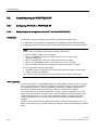
Preface
Purpose of the operating instructions
The information in these operating instructions is intended to enable you to operate the
ET 200S Distributed I/O System:
● on the PROFIBUS DP as DP Slave
● as a PROFINET IO device on PROFINET
Required level of knowledge
To understand these operating instructions, you should have general experience in the field
of automation engineering.
Scope of these operating instructions
These operating instructions are valid for the components of the ET 200S Distributed I/O
System.
These operating instructions contain a description of the components which were valid at the
time the manual was published. We reserve the right to enclose a product information
bulletin containing up-to-date information regarding new components and new versions of
components.
Standards and approvals
In Chapter General technical data, you will find information about standards, certificates and
approvals (Page 127)
ET 200S
Operating Instructions, 08/2008, A5E00515771-06
3
Preface
Position in the information landscape
The following manuals are available for ET 200S:
Manual
ET 200S Distributed I/O System Operating Instructions (http://support.automation.siemens.com/WW/view/en/1144348)
ET 200S Distributed I/O System Manuals:
• IM 151-1 Interface Modules (http://support.automation.siemens.com/WW/view/en/10805259/133000)
• IM 151-3 PN Interface Modules (http://support.automation.siemens.com/WW/view/en/19241998/133000)
• Interface Modules with Integrated CPU (http://support.automation.siemens.com/WW/view/en/10805260/133000)
• PM-E Power Modules (http://support.automation.siemens.com/WW/view/en/10805261/133000)
• Reserve Modules (http://support.automation.siemens.com/WW/view/en/14902665/133000)
• Digital Electronic Modules (http://support.automation.siemens.com/WW/view/en/10805262/133000)
• Analog Electronic Modules (http://support.automation.siemens.com/WW/view/en/10805263/133000)
Fail-Safe Modules (http://support.automation.siemens.com/WW/view/en/12461959/133000)
IO-Link Modules and Sensors (http://support.automation.siemens.com/WW/view/en/29773950/133300)
IQ-Sense Modules and Sensors (http://support.automation.siemens.com/WW/view/en/10805264/133000)
Technology modules (http://support.automation.siemens.com/WW/view/en/10805265/133000)
Terminal Modules for Power and Electronic Modules
(http://support.automation.siemens.com/WW/view/en/10805266/133000)
Motor Starters and Frequency Converters (http://support.automation.siemens.com/WW/view/en/18687280/133000)
Safety Motor Starters and Fail-Safe Frequency Converters
(http://support.automation.siemens.com/WW/view/en/18687280/133000)
PROFINET System Description (http://support.automation.siemens.com/WW/view/en/19292127)
From PROFIBUS DP to PROFINET IO (http://support.automation.siemens.com/WW/view/en/19289930)
ET 200S IM151-7 CPU Interface Module (http://support.automation.siemens.com/WW/view/en/12714722) and Operation
List
ET 200S 1 SI Serial Interface Modules (http://support.automation.siemens.com/WW/view/en/9260793)
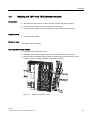
Weighing Technology for the ET 200S
• SIWAREX CS (http://support.automation.siemens.com/WW/view/en/19250865)
• SIWAREX CF (http://support.automation.siemens.com/WW/view/en/21320470)
4
ET 200S
Operating Instructions, 08/2008, A5E00515771-06
Preface
Guide
The operating instructions contain the following guides which provide quick access to the
specific information you need:
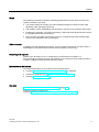
● You will find a table of contents and a list of tables and figures in the document at the
beginning of the operating instructions.
● The chapters contain subheadings that provide an overview of the content of the section.
● Following the appendix, you will find a glossary in which important technical terms used in
the operating instructions are defined.
● At the end of the operating instructions, there is a comprehensive index enabling rapid
access to the information you are looking for.
Other manuals
In addition to these operating instructions, you also need the manual for your DP master or
PROFINET IO Controller and the manuals for the modules you are using.
Recycling and disposal
Thanks to the fact that it is low in contaminants, the ET 200S is recyclable. For
environmentally compliant recycling and disposal of your electronic waste, please contact a
company certified for the disposal of electronic waste.
Information on the Internet
You can find information on the Internet on the following topics:
● Contacts (http://www.siemens.com/automation/partner) for SIMATIC
● Contacts for SIMATIC NET (http://www.siemens.com/simatic-net)
● Training (http://www.sitrain.com)
See also
Order numbers for ET 200S network components (Page 138)
Technical Support, Contacts and
Training (http://support.automation.siemens.com/WW/view/en/19293011)
ET 200S
Operating Instructions, 08/2008, A5E00515771-06
5
Preface
6
ET 200S
Operating Instructions, 08/2008, A5E00515771-06
Table of contents
Preface ...................................................................................................................................................... 3
1
2
3
Description............................................................................................................................................... 11
1.1
What are distributed I/O systems?...............................................................................................11
1.2
What is PROFINET IO? ...............................................................................................................13
1.3
What is the ET 200S distributed I/O system? ..............................................................................14
Brief instructions on commissioning ET 200S .......................................................................................... 21
2.1
2.1.1
2.1.2
2.1.3
2.1.4
2.1.5
2.1.6
2.1.7
Commissioning on PROFIBUS DP..............................................................................................21
Introduction ..................................................................................................................................21
Install the ET 200S.......................................................................................................................23
Wiring and assembling ET 200S..................................................................................................24
Configuring ET 200S in the SIMATIC manager...........................................................................25
Creating a user program ..............................................................................................................26
Switching on ET 200S..................................................................................................................26
Evaluating diagnostic messages..................................................................................................27
2.2
2.2.1
2.2.2
2.2.3
2.2.4
2.2.5
2.2.6
2.2.7
2.2.8
Commissioning on PROFINET IO ...............................................................................................30
Introduction ..................................................................................................................................30
Installing and wiring ET 200S ......................................................................................................32
Configuring ET 200S in the SIMATIC manager...........................................................................34
Assigning device names for the IO device...................................................................................35
Creating a user program ..............................................................................................................36
Switching on ET 200S..................................................................................................................36
Evaluating diagnostic messages..................................................................................................37
Evaluating diagnostic messages..................................................................................................38
Application planning................................................................................................................................. 41
3.1
Switching on the ET 200S............................................................................................................41
3.2
Use of the ET 200S in a redundant system .................................................................................42
3.3
Limitation of connectable modules/maximum configuration ........................................................43
3.4
3.4.1
3.4.2
3.4.3
Application of power modules ......................................................................................................45
Placing power modules and connecting them to common potential............................................45
Example of a configuration: Terminal modules for power modules.............................................47
Finding the correct power module for an I/O device ....................................................................49
ET 200S
Operating Instructions, 08/2008, A5E00515771-06
7
Table of contents
4
5
6
8
Installing .................................................................................................................................................. 51
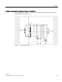
4.1
Basic principles of installation ..................................................................................................... 51
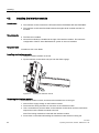
4.2
Installing the interface module .................................................................................................... 54
4.3
Installing the TM-P and TM-E terminal modules......................................................................... 55
4.4
Installing the terminal modules TM-C for COMPACT modules .................................................. 57
4.5
Installing add-on terminals .......................................................................................................... 59
4.6
Removing/installing pluggable bridges on the additional terminal .............................................. 63
4.7
Replacing the terminal box on the terminal module.................................................................... 64
4.8
Installing the bus terminating module ......................................................................................... 66
4.9
Installing the shield contact ......................................................................................................... 67
4.10
Applying slot number labels and color identification labels......................................................... 69
4.11
Mounting Color Identification Labels for ET 200S and ET 200S COMPACT ............................. 71
Wiring and assembly ............................................................................................................................... 73
5.1
General rules and regulations for operating the ET 200S .......................................................... 73
5.2
Operating the ET 200S on a grounded incoming supply ............................................................ 75
5.3
Electrical configuration of the ET 200S....................................................................................... 78
5.4
5.4.1
5.4.2
5.4.3
5.4.4
5.4.5
5.4.6
5.4.7
5.4.8
5.4.9
Wiring the ET 200S ..................................................................................................................... 79
Wiring rules for the ET 200S ....................................................................................................... 79
Wiring a terminal module with screw-type terminals................................................................... 79
Wiring a Terminal Module with Spring Terminals ....................................................................... 80
Wiring terminal modules with Fast Connect................................................................................ 81
Wiring terminal modules.............................................................................................................. 84
Wiring an interface module with PROFIBUS DP interface (electrically) ..................................... 87
Wiring an interface module with PROFIBUS DP interface (optically) ......................................... 88
Wiring an interface module with PROFINET IO interface (electrically) ...................................... 92
Wiring the power supply.............................................................................................................. 94
5.5
5.5.1
5.5.2
Plugging and removing electronic modules and COMPACT modules ....................................... 95
Plug and label electronic or COMPACT modules ....................................................................... 95
Removing and inserting modules during operation .................................................................... 99
Commissioning ...................................................................................................................................... 101
6.1
Safety tests prior to commissioning .......................................................................................... 101
6.2
6.2.1
6.2.1.1
6.2.1.2
6.2.1.3
6.2.1.4
6.2.1.5
6.2.1.6
6.2.2
6.2.2.1
6.2.2.2
6.2.2.3
Commissioning on PROFIBUS DP ........................................................................................... 102
Configuring ET 200S on PROFIBUS DP .................................................................................. 102
Basic principles of configuration for the ET 200S on PROFIBUS DP ...................................... 102
Combining modules for configuration ....................................................................................... 103
Grouping of digital input modules ............................................................................................. 106
Grouping of digital output modules ........................................................................................... 107
Grouping of motor starters ........................................................................................................ 108
Example of a configuration........................................................................................................ 109
Commissioning and startup of ET 200S on PROFIBUS DP..................................................... 111
Setting the PROFIBUS Address ............................................................................................... 111
Commissioning ET 200S on PROFIBUS DP ............................................................................ 113
Startup of the ET 200S on PROFIBUS DP ............................................................................... 114
ET 200S
Operating Instructions, 08/2008, A5E00515771-06
Table of contents
6.3
6.3.1
6.3.2
6.3.3
6.3.4
7
8
A
B
C
Functions ............................................................................................................................................... 123
7.1
Direct data exchange on PROFIBUS DP ..................................................................................123
7.2
7.2.1
Option handling on the PROFIBUS DP .....................................................................................125
Basic principles of option handling on PROFIBUS DP..............................................................125
7.3
Identification data.......................................................................................................................126
General technical specifications ............................................................................................................ 127
8.1
Standards and approvals ...........................................................................................................127
8.2
Electromagnetic compatibility ....................................................................................................131
8.3
Transport and storage conditions ..............................................................................................132
8.4
Mechanical and Climatic Ambient Conditions............................................................................133
8.5
Specifications concerning insulation tests, protection class, and rated voltage for ET 200S....135
8.6
Variations in general technical specifications for the ET 200S FC frequency converter ...........136
8.7
Use of ET 200S in a zone 2 potentially explosive environments...............................................136
Order numbers ...................................................................................................................................... 137
A.1
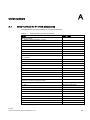
Order numbers for ET 200S accessories ..................................................................................137
A.2
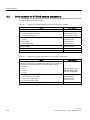
Order numbers for ET 200S network components ....................................................................138
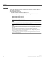
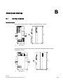
Dimensional drawings............................................................................................................................ 139
B.1
Interface modules ......................................................................................................................139
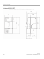
B.2
Terminal module for COMPACT module with COMPACT module inserted..............................141
B.3
Terminal modules with an electronic module inserted...............................................................141
B.4
Terminating module ...................................................................................................................145
B.5
Shield contact.............................................................................................................................146
B.6
Additional terminal .....................................................................................................................146
Leakage resistance................................................................................................................................ 147
C.1
D
Commissioning on PROFINET IO .............................................................................................115
Configuring the ET 200S on the PROFINET IO ........................................................................115
Assigning device names to the I/O device.................................................................................116
Combing modules for the configuration .....................................................................................118
Commissioning and startup of ET 200S on the PROFINET IO .................................................120
Establishing the leakage resistance of an ET 200S station.......................................................147
Interference-free operation .................................................................................................................... 149
D.1
Special Measures for Interference-Free Operation ...................................................................149
Glosary ................................................................................................................................................. 153
Index...................................................................................................................................................... 161
ET 200S
Operating Instructions, 08/2008, A5E00515771-06
9
Table of contents
10
ET 200S
Operating Instructions, 08/2008, A5E00515771-06
Description
1.1
1
What are distributed I/O systems?
Distributed I/O systems
When a system is configured the I/Os from and/or to the process are often integrated
centrally in the automation system.
Circuitry wiring that covers great distances between the I/O and the automation system may
become very complex and confusing. Electromagnetic interference can therefore impair
reliability.
Distributed I/O provides the ideal solution for such systems:
● The controller CPU is located centrally
● The I/O systems (inputs and outputs) operate decentrally on-site
● The high-performance PROFIBUS DP system provides high-speed data transmission for
reliable communication between the controller CPU and the I/O system
What is PROFIBUS DP?
PROFIBUS DP is an open bus system according to the standard IEC 61784-1:2002
Ed1 CP 3/1 with the "DP" protocol (DP = Distributed Periphery).
Physically, PROFIBUS DP is either an electrical network based on a shielded two-wire line
or an optical network based on a fiber-optic cable.
The "DP" is a high-speed protocol for cyclic data exchange between the controller CPU and
the distributed I/O systems.
What is a DP master and what are DP slaves?
The DP master links the controller CPU with the distributed I/O systems. The DP master
exchanges data with the distributed I/O systems via PROFIBUS DP. It also monitors the
PROFIBUS DP.
The distributed I/O systems (= DP slaves) prepare the encoder and actuator data on site in
such a way that it can be transmitted via the PROFIBUS DP to the controller CPU.
Which devices can be connected to PROFIBUS DP?
PROFIBUS DP supports a wide variety of devices for operation such as DP master or DP
slave, provided they operate in compliance with the standard IEC61784-1:2002 Ed1 CP 3/1.
These include devices from the following product families:
● SIMATIC S7/C7
● SIMATIC PD/PC
● SIMATIC HMI (control and monitoring devices OP, OS, TD)
● Devices from other vendors
ET 200S
Operating Instructions, 08/2008, A5E00515771-06
11
Description
1.1 What are distributed I/O systems?
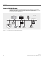
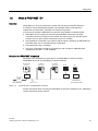
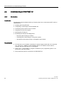
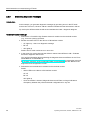
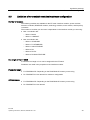
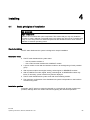
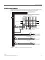
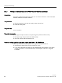
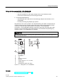
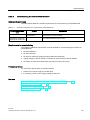
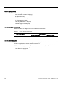
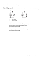
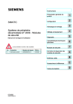
Structure of a PROFIBUS DP network
The figure below illustrates a typical PROFIBUS DP network structure. The DP master is
integrated in the respective device. For example, the S7-400 is equipped with a
PROFIBUS DP interface. The DP slaves are the distributed I/O systems that are linked with
the DP masters via the PROFIBUS DP.
6
6
3*3&
'3PDVWHU
352),%86'3
'3VODYHV
(7SUR
(76
Figure 1-1
12
(70
'ULYH
6
'3$6,/,1.
2326
2WKHUILHOGGHYLFHV
The typical structure of a PROFIBUS DP network
ET 200S
Operating Instructions, 08/2008, A5E00515771-06
Description
1.2 What is PROFINET IO?
1.2
What is PROFINET IO?
Definition
PROFINET IO is an open transmission system with real-time functionality defined in
accordance with the PROFINET standard. This standard defines a manufacturerindependent communication, automation and engineering model.
Accessories for wiring the PROFINET components are available in industrial quality.
● PROFINET does not deploy the hierarchical PROFIBUS master/slave principle.
A provider/consumer principle is used instead. The planning process specifies which
modules of an IO device will be subscribed to by an IO controller.
● The quantities are extended in accordance with the options offered by the PROFINET IO.
Parameter limits are not exceeded during configuration.
● The transmission rate is 100 Mbps.
● The user's configuration interface is generally the same as that on PROFIBUS DP
(configuration in STEP 7 → HW CONFIG).
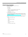
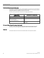
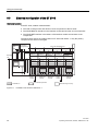
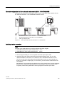
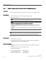
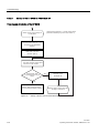
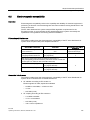
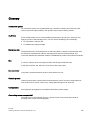
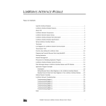
Structure of a PROFINET IO network
The figure below illustrates the typical layout of a PROFINET IO network. Existing
PROFIBUS slaves can be integrated by using an IE/PB link.
,2FRQWUROOHU
6
,2GHYLFH
(76
6ZLWFK
,2GHYLFH
(76
23
6ZLWFK
3*
6ZLWFK
,(3%
/LQN
352),%86'3
Figure 1-2
0D[P
352),1(7,2
,QGXVWULDO(WKHUQHW
Typical structure of a PROFINET IO network
Further information about structuring a PROFINET IO network is available in the PROFINET
System Description system manual.
ET 200S
Operating Instructions, 08/2008, A5E00515771-06
13
Description
1.3 What is the ET 200S distributed I/O system?
1.3
What is the ET 200S distributed I/O system?
Definition
The ET 200S distributed I/O system is a discretely modular, highly flexible DP slave for
connection to process signals on a central controller or a field bus. ET 200S supports field
bus types PROFIBUS DP and PROFINET IO. ET 200S has protection class IP 20.
Applications
You can connect virtually any number of I/O modules in virtually any combination right next
to the interface module that transfers the data to the central controller. You can thus set the
focus of your configuration on local requirements.
Depending on the interface module, each ET 200S can consist of up to 63 modules - for
example, power modules, I/O modules, and motor starters.
The fact that motor starters can be integrated (switching and protecting any three-phase load
up to 7.5 kW) ensures that the ET 200S can be quickly adapted to suit virtually any processrelated use of your machine.
The fail-safe modules of the ET 200S ensure the fail-safe reading and output of data to
safety category 4 (EN 954-1).
Terminal modules and electronic modules
The ET 200S distributed I/O system is
● Connected to PROFIBUS DP by a cable connector for PROFIBUS DP at the IM151-1 or
IM151-1 COMPACT interface module and
● Connected to PROFINET IO by a cable connector for PROFINET IO at the IM151-3
interface module.
Every ET 200S peripheral system is
● A DP slave on the PROFIBUS DP, or
● An IO device on the PROFINET IO.
14
ET 200S
Operating Instructions, 08/2008, A5E00515771-06
Description
1.3 What is the ET 200S distributed I/O system?
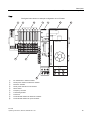
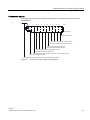
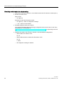
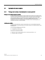
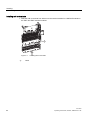
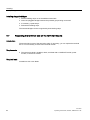
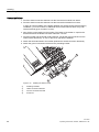
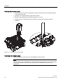
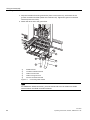
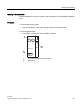
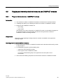
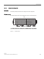
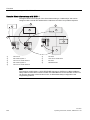
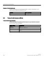
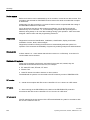
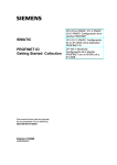
View
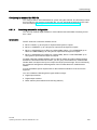
The figure below shows an example configuration of an ET 200S.
1
2
3
4
5
6
7
IPM25 FSA
10
9
8
①
ET 200S IM151-1 interface module
②
PM-E power module for electronic modules
③
Electronic modules
④
PM-D power module for motor starters
⑤
Direct starter
⑥
Frequency converter
⑦
Terminating module
⑧
Power bus
⑨
TM-E terminal modules for electronic modules
⑩
TM-P terminal modules for power modules
ET 200S
Operating Instructions, 08/2008, A5E00515771-06
15
Description
1.3 What is the ET 200S distributed I/O system?
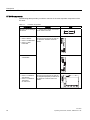
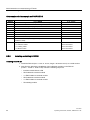
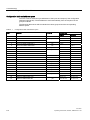
ET 200S components
The following table provides you with an overview of the most important components of the
ET 200S:
Table 1- 1
ET 200S components
Components
Function
View
Mounting rail according to ... ...carries the ET 200S. You mount
EN 60715
the ET 200S on the rail.
Interface module
• IM151-1 BASIC
• IM151-1 STANDARD
• IM151-1 HIGH
FEATURE
•
IM151-1 FO
STANDARD
COMPACTModule
• IM151-1 COMPACT
32DI DC24V
• IM151-1 COMPACT
16DI/16DO
24 VDC/0.5 A
16
... ...connects the ET 200S with the
DP master and prepares the data for
the electronic modules and motor
starters.
with RS485 interface:
with fiber-optic interface:
... ...connects the ET 200S with the
DP master and prepares the data for
the integrated periphery as well as for
any electronic modules and motor
starters.
with RS485 interface:
ET 200S
Operating Instructions, 08/2008, A5E00515771-06
Description
1.3 What is the ET 200S distributed I/O system?
Components
Function
Terminal module for
COMPACT modules
... ...carries the wiring and
accommodates COMPACT modules.
Terminal modules for COMPACT
modules are available in the following
versions:
• With screw-type terminal
• With spring-loaded terminal
Terminal module for
power and electronic
modules
... ...provides the electrical and
mechanical connection to the ET
200S module.
Terminal modules versions available:
• For power modules
• For electronic modules
• With screw-type terminal
• With spring-loaded terminal
• With Fast Connect (quick
connection method, no stripping
required)
Add-on terminal for
• Terminal module for
COMPACT modules
• Any terminal modules
with a width of 120
mm
... ...extends the terminal block and
enables the connection of sensors /
actuators for the individual channels
in 3 or 4 conductor technology
Additional terminals are available in
the following variants:
• With screw-type terminal
• With spring-loaded terminal
Power module
... Monitors the voltage for all the
electronic modules in the potential
group. The following power modules
are available:
• For a 24 VDC supply with
diagnostics
• For a 24 to 48 VDC supply with
diagnostics
• For a 24 to 48 VDC, 24 to
230 VAC supply with diagnostics
and fuse
ET 200S
Operating Instructions, 08/2008, A5E00515771-06
View
17
Description
1.3 What is the ET 200S distributed I/O system?
18
... ...is inserted onto the terminal
module and determines the function:
• Digital output modules with
24 VDC, 120 /230 VAC and
NAMUR
• Digital output modules with
24 VDC and 120/230 VAC
• Relay modules
• Analog input modules with
voltage, current, and resistance
measurement, thermoresistor and
thermocouple elements
• Analog output modules for voltage
and current
• Technology modules
• Weighing modules SIWAREX CS
and SIWAREX CF
• Fail-safe modules
• RESERVE modules
Terminating module
... ...terminates the ET 200S and can
be used to carry 6 reserve fuses (5
mm x 20 mm).
Shield contact
... ...is a pluggable mount for 3 x 10
mm standard power busbars and
enables a low-impedance cable
shielding to be applied with minimal
installation time.
Labeling sheet
(DIN A4, perforated, foil)
... ...for machine labeling or printing
• 80 strips per labeling sheet for
interface modules and electronic
modules
• 10 strips per labeling sheet for
COMPACT modules
Slot number plates
... ...used to identify the slots of the
terminal module.
63
Electronic module
62
View
2
Function
1
Components
ET 200S
Operating Instructions, 08/2008, A5E00515771-06
Description
1.3 What is the ET 200S distributed I/O system?
Components
Function
View
Color-coded labels
... ...allow customer/country specific
identification of the terminals on the
terminal module
PROFIBUS cable with
bus terminal connector
... ...combines nodes of a PROFIBUS
DP configuration with each other.
Fiber-optic duplex cable
with simplex plug
(in the plug adaptor for
IM151- 1 FO
STANDARD)
... ...combines nodes of a PROFIBUS
DP configuration with each other.
Interface module
• IM151-3 PN
• IM151-3 PN HIGH
FEATURE
... ...connects the ET 200S with
PROFINET IO controllers and
prepares the data for the electronic
modules and motor starters.
PROFINET connector as
per the specifications in
the PROFINET
Installation Guide and
Industrial Ethernet FC
installation lines
... ...connects nodes of a
PROFINET IO configuration with one
another.
With 2 PROFINET interfaces:
Characteristics and advantages of the ET 200S
The table below presents the properties and benefits of ET 200S.
Table 1- 2
Characteristics and advantages of the ET 200S
Properties
Advantages
About the structure
Function-oriented, cost-optimized station
design
Significant reduction of cost and effort for
configuration and documentation
Space saving due to the ability to string
modules together in random order
Discretely modular design
• 1-, 2-, 4- and 8-channel electronic modules
• Power modules
• Integrated motor starters
• 32-channel COMPACT modules
•
Extensive range of electronic modules
Broad area of application
ET 200S
Operating Instructions, 08/2008, A5E00515771-06
•
•
19
Description
1.3 What is the ET 200S distributed I/O system?
Properties
Advantages
ET 200S FC frequency converter
•
•
•
•
Speed control
Fail-safe technology: Safe braking ramp, safe
speed reduction
Regeneration into grid when motor in
generator mode
No grid commutation reactor required
Communication-capable, system-integrated
motor starters: Direct and reversing starter up to
7.5 kW
PLC inputs and outputs, terminal blocks, circuit
breakers and contactors in a plug-in module save
space and the effort involved in wiring
Permanent wiring due to the separation of
mechanical and electronic components
•
•
Prewiring possible
Module replacement during operation of the
ET 200S ("hot swapping")
Individual connection of power modules to
common potential
•
Individual formation of potential groups
(identifiable by color coding of the TM-P
terminal modules for power modules)
Simple load interruption
•
Robust structure for rough industrial conditions (5
g vibration resistance)
High operating reliability when mounted directly
on the machine, high availability
Connection system
Integrated voltage buses
Reduced effort required for wiring
Power bus up to 50 A for motor starters
Minimization of wiring in 400 V range
Screw-type terminals, spring-loaded terminals,
and Fast Connect
A change in terminal connection method is not
necessary
•
•
2- and 3-conductor connection or
2-, 3- and 4-conductor connection
Optimal selection in terms of space and cost
Connection method with no stripping required
Time saving during wiring
Fast Connect
•
•
Replaceable terminal box in the terminal module
No need to remove the terminal module in the
event of terminal damage
Automatic coding of the I/O modules
Quick and reliable module replacement
Large label plate
Adequate space for clear labeling
High data transmission speed of up to 12 Mbps
on PROFIBUS DP and 100 Mbps on
PROFINET IO
Short response times
Integrated safety functions
Savings on time-consuming safety engineering
For motor starters up to safety category
4 according to EN 954-1
Fail-safe modules
20
For acquiring and outputting fail-safe signals via
PROFINET (PROFIsafe) up to SIL3 in
accordance with IEC 61508, Category 4 in
accordance with EN 954-1, and Performance
Level e in accordance with ISO 13849.
ET 200S
Operating Instructions, 08/2008, A5E00515771-06
Brief instructions on commissioning ET 200S
2.1
Commissioning on PROFIBUS DP
2.1.1
Introduction
2
Introduction
The following simple examples will teach you how to commission the ET 200S on the
PROFIBUS DP step by step:
● ET 200S installation and wiring up
● Configuring ET 200S in the SIMATIC manager
● Creating a user program
● Switching on ET 200S
● Evaluating diagnostic messages:
– Removing and inserting of modules
– Switching off the load voltage on the power module
– Wire break in the actuator wiring on the digital output module
Requirements
● You have set up an S7 station consisting of a power supply component and a DP master
(e.g. CPU 315-2 DP). For this example a CPU 315-2 DP is used as the DP master. You
can of course use any other DP master (standard IEC 61784-1:2002 Ed1 CP 3/1).
● STEP 7 (V5.0 with ServicePack 3 or higher) is installed on your programming device. You
know how to work with STEP 7.
● The PD must be connected to the DP master.
ET 200S
Operating Instructions, 08/2008, A5E00515771-06
21
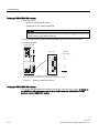
Brief instructions on commissioning ET 200S
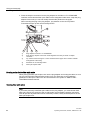
2.1 Commissioning on PROFIBUS DP
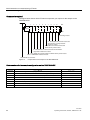
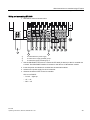
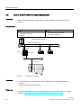
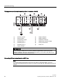
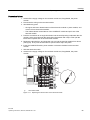
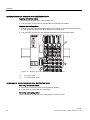
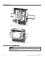
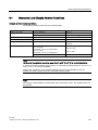
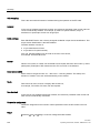
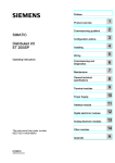
Components required
The figure below shows which ET 200S components you require for the sample on the
PROFIBUS DP:
,0
30 ', ',
',
', 30 '2 '2 '2 '2
6ORW
5DLO
7HUPLQDWLQJPRGXOH
[70(1$WHUPLQDOPRGXOHDQG
'2'&9$+LJK)HDWXUH
HOHFWURQLFPRGXOH
7031$WHUPLQDOPRGXOHDQG
30('&9SRZHUPRGXOH
[70(1$WHUPLQDOPRGXOHDQG','&9
+LJK)HDWXUHHOHFWURQLFPRGXOH
7031$WHUPLQDOPRGXOHDQG30('&9SRZHUPRGXOH
,067$1'$5'LQWHUIDFHPRGXOH
352),%86EXVFRQQHFWRU
Figure 2-1
Components for the sample on the PROFIBUS DP
Order numbers for the sample configuration on the PROFIBUS DP
Quantity
22
Ordering data
Order No.:
1×
Standard mounting rail 35 mm ( length = 483 mm, for example)
6ES5710-8MA11
1×
IM151-1 STANDARD interface module and terminating module 1 piece
6ES7151-1AA04-0AB0
2×
Fast Connect terminal module TM-P15N23-A1, 1 piece
6ES7193-4CC70-0AA0
2×
Fast Connect terminal module TM-E15N24-A1, 5 pieces
6ES7193-4CA70-0AA0
2×
PM-E DC24V, 1 piece
6ES7138-4CA01-0AB0
1×
2DI DC24V HF, 5 pieces
6ES7131-4BB01-0AB0
1×
2DO DC24V/0,5A HF, 5 pieces
6ES7132-4BB01-0AB0
1×
Bus connector
6ES7972-0BA12-0XA0
ET 200S
Operating Instructions, 08/2008, A5E00515771-06
Brief instructions on commissioning ET 200S
2.1 Commissioning on PROFIBUS DP
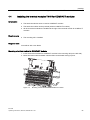
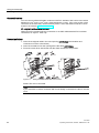
2.1.2
Install the ET 200S
Proceed as follows
1. Install the DIN rail (35 x 7.5 mm or 15 mm) with a length of at least 210 mm on a solid
surface.
2. Mount the various modules onto the rail, starting on the left side (hang in - swivel down slide to left.) Follow the following sequence:
– Interface module IM151-1 STANDARD
– TM-P15N23-A1 terminal module
– 4 x TM-E15N24-A1 terminal module
– TM-P15N23-A1 terminal module
– 4 x TM-E15N24-A1 terminal module
– Terminating module
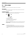
3. Set PROFIBUS address 3 on the IM 151-1 STANDARD interface module.
2)) 21
Figure 2-2
*
Setting PROFIBUS address 3
Intended for use with future add ins. Switch must be in OFF position.
ET 200S
Operating Instructions, 08/2008, A5E00515771-06
23
Brief instructions on commissioning ET 200S
2.1 Commissioning on PROFIBUS DP
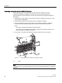
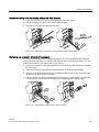
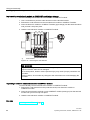
2.1.3
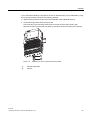
Wiring and assembling ET 200S
Proceed as follows
1. Wire the ET 200S as shown below:
$8;
$8;
$
$
/ 0
1
2
①
24 VDC electronic power supply
②
24 VDC sensor supply voltage group 1
③
24 VDC load supply voltage group 2
3
1. Use the PROFIBUS bus connector to connect the DP master with the ET 200S. The
PROFIBUS DP interface is located on the IM 151-1 STANDARD.
2. Insert the power and electronic modules into the terminal modules.
3. Switch on the supply voltage for the DP master.
4. Observe the status LEDs on the DP master.
CPU 315-2 DP:
– 5 VDC → lights up
– SF DP → off
– BUSF → off
24
ET 200S
Operating Instructions, 08/2008, A5E00515771-06
Brief instructions on commissioning ET 200S
2.1 Commissioning on PROFIBUS DP
2.1.4
Configuring ET 200S in the SIMATIC manager
Proceed as follows
1. Start SIMATIC Manager, and create a new project with a DP master
(e. g., CPU315-2 DP). Create OB 1, OB 82 and OB 122 for the project.
2. Create the PROFIBUS subnet.
3. Connect the PROFIBUS subnet with the DP master in HW Config.
4. Take the ET 200S from the hardware catalog and put it on the PROFIBUS.
5. Set the PROFIBUS address 3 for the ET200S.
6. Drag the individual ET 200S modules from the hardware catalog to the configuration
table.
7. Mark the electronic modules in the configuration table, and click the "Pack addresses"
button.
Table 2- 1
Configuration table in HW Config for PROFIBUS DP
Module/
DP identification
Order No.:
I address
Q address
Comment
1
6ES7138-4CA01-0AA0 PM-E DC24V
Power module
2
6ES7131-4BB01-0AB0 2DI DC24V
3
6ES7131-4BB01-0AB0 2DI DC24V
Bytes 0.2 and 0.3
4
6ES7131-4BB01-0AB0 2DI DC24V
Bytes 0.4 and 0.5
5
6ES7131-4BB01-0AB0 2DI DC24V
Byte 0.6 and 0.7
6
6ES7138-4CA01-0AA0 PM-E DC24V
Power module
7
6ES7132-4BB01-0AB0 2DO DC24V
8
6ES7132-4BB01-0AB0 2DO DC24V
Bytes 0.2 and 0.3
9
6ES7132-4BB01-0AB0 2DO DC24V
Bytes 0.4 and 0.5
10
6ES7132-4BB01-0AB0 2DO DC24V
Byte 0.6 and 0.7
0
Bytes 0.0 and 0.1
0
Bytes 0.0 and 0.1
1. Set the following parameters:
– In the DP slave properties dialog box for ET 200S:
Startup for set- <> actual configuration: enable
– In the DP slave properties dialog box for the PM-E DC24V, Module/DP ID 1 (in the
configuration table)
Diagnostics: Missing load voltage
– In the DP slave properties dialog box for the 2 DO DC24V, Module/DP ID 7 (in the
configuration table)
Diagnostics: Wire break A0
2. Save the configuration.
ET 200S
Operating Instructions, 08/2008, A5E00515771-06
25
Brief instructions on commissioning ET 200S
2.1 Commissioning on PROFIBUS DP
2.1.5
Creating a user program
Proceed as follows
1. Create the user program in the LAD/STL/FBD editor in OB 1.
Example 1: Reading an input and triggering an output:
STL
U I 0.0
If input byte 0.0 and
U M 2.0
memory bit 2.0 is set, then
S O 0.0
set output byte 0.0
Example 2: Transferring an input byte to an output byte:
STL
L PEB 0
Load I/O input byte 0 in the accumulator
(bytes 0.0 to 0.7)
T PAB 0
Transfer the accumulator content to
I/O output byte 0 (bytes 0.0 to 0.7)
1. Save the project in SIMATIC Manager.
2. Download the configuration to the DP master.
2.1.6
Switching on ET 200S
Proceed as follows
1. Switch on all the power supplies on the ET 200S.
2. Observe the status LEDs on the DP master and ET 200S.
– CPU 315-2 DP:
DC 5V: lights up
SF DP: off
BUSF: off
– ET 200S:
SF: off
BF: off
ON: lights up
26
ET 200S
Operating Instructions, 08/2008, A5E00515771-06
Brief instructions on commissioning ET 200S
2.1 Commissioning on PROFIBUS DP
2.1.7
Evaluating diagnostic messages
Introduction
In this example, you generate diagnostic messages by provoking errors on the ET 200S. In
the event of an error, OB 82 is started. You evaluate the start information in OB 82.
Tip: Call SFC13 in OB 82, and evaluate the diagnostic frame.
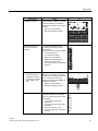
Removing and inserting the 2 DI DC24V HF digital electronic module
1. Remove the 2 DI DC24V HF electronic module from the terminal module during
operation.
2. Observe the status LEDs on the IM 151-1 STANDARD:
– SF: lights up → there is a diagnostic message.
– BF: off
– ON: lights up
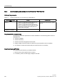
Result: The ET 200S continues to run error-free.
3. Evaluate the diagnostic information:
Result:
– Station status 1 (byte 0): Bit 3 is set → external diagnostics
– ID-related diagnostics: Byte 7.1 is set → slot 2
– Module status: bytes 19.2 / 19.3: 11B → no module
4. Reinsert the removed electronic module into the terminal module.
Result:
– Status LED on the IM 151-1 STANDARD:
SF: off
BF: off
ON: lights up
– The diagnostic message is deleted.
ET 200S
Operating Instructions, 08/2008, A5E00515771-06
27
Brief instructions on commissioning ET 200S
2.1 Commissioning on PROFIBUS DP
Switching off load voltage on the power module
1. Switch off the load voltage on the PM-E DC24V (slot 1).
2. Monitor the status LEDs.
IM151-1 STANDARD:
– SF: lights up
Power module:
– PWR: off → no load voltage available on the power module
– SF: lights up → there is a diagnostic message.
I/O modules in the voltage group:
– LEDs: light up
3. Evaluate the diagnostics.
Result:
– Station status 1 (byte 0): Bit 3 is set → external diagnostics
– ID-related diagnostics: Byte 7.0 is set → slot 1
– Channel-specific diagnostics:
Bytes 35.0 to 35.5: 000000B → slot 1
Bytes 37.0 to 37.4: 10001B → sensor or load voltage missing
4. Switch on the load voltage back on the power module and re-evaluate the diagnostics.
Result:
– Status LED on the IM 151-1 STANDARD:
SF: off
– Status LEDs on power module:
PWR: on
SF: off
– Status LEDs on I/O modules:
LEDs: off
– The diagnostic message is deleted.
28
ET 200S
Operating Instructions, 08/2008, A5E00515771-06
Brief instructions on commissioning ET 200S
2.1 Commissioning on PROFIBUS DP
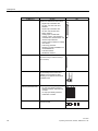
Simulating a wire break in the actuator wiring
1. Remove the cable from terminal 1 on the 2DO DC24V/0.5A HF electronic module (slot 7)
2. Monitor the status LEDs:
IM151-1 STANDARD:
– SF: lights up
Electronic module 2DO DC24V/0.5A HF:
– SF: lights up → there is a diagnostic message
– 1: off → output is not activated
3. Evaluate the diagnostic information:
Result:
– Station status 1 (byte 0): Bit 3 is set → external diagnostics
– ID-related diagnostics: Byte 7.6 is set → slot 7
– Channel-specific diagnostics:
Bytes 35.0 to 35.5: 000110B → slot 7
Bytes 36.0 to 35.5: 000000B → channel 0
Bytes 37.0 to 37.4: 00110B → wire break
4. Reattach the cable to the actuator in terminal 1 and reevaluate the diagnostics:
– Status LED on the IM 151-1 STANDARD:
SF: off
– Status LEDs electronic module 2DO DC24V/0.5 A HF:
SF: off
1: off/on
– The diagnostic message is deleted.
ET 200S
Operating Instructions, 08/2008, A5E00515771-06
29
Brief instructions on commissioning ET 200S
2.2 Commissioning on PROFINET IO
2.2
Commissioning on PROFINET IO
2.2.1
Introduction
Introduction
The following simple example teaches you step by step how to commission the ET 200S on
PROFINET IO:
● Installing and wiring ET 200S
● Configuring in HW Config or with the GSDML file
● Transferring device names to the IO device
● Integrating into the user program
● Switching the ET 200S on
● Evaluating the interrupts and diagnostics:
– Removing and inserting of modules
– Switching off the load voltage on the power module
– Wire break in the actuator wiring on the digital output module
Requirements
● You have set up an S7 station consisting of a power supply module and an IO controller
(e.g., CPU 317-2 PN/DP). In this example a CPU 317-2 PN/DP is used as the IO
controller with firmware version V2.3 and higher.
● STEP 7 V 5.3 + ServicePack 1 or higher is installed on your programming device. You
know how to work with STEP 7.
● The programming device connected to the PROFINET IO.
30
ET 200S
Operating Instructions, 08/2008, A5E00515771-06
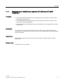
Brief instructions on commissioning ET 200S
2.2 Commissioning on PROFINET IO
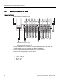
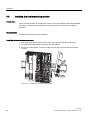
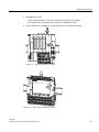
Components required
The figure below shows which ET 200S components you require for the example on the
PROFINET IO:
30 ', ',
',
', 30 '2 '2 '2 '2
6ORW
,0
31
0RXQWLQJUDLO
7HUPLQDWLQJPRGXOH
[7HUPLQDOPRGXOH70(1$DQG
HOHFWURQLFPRGXOH'2'&9$+)
7HUPLQDOPRGXOH7031$
DQGSRZHUPRGXOH30('&9
[7HUPLQDWLQJPRGXOH70(1$DQG
HOHFWURQLFPRGXOH','&9+)
7HUPLQDO0RGXOH7031$DQGSRZHUPRGXOH30('&9
,0b31LQWHUIDFHPRGXOH
,QGXVWULDO(WKHUQHW)&LQVWDOODWLRQFDEOHZLWK352),1(7FRQQHFWRU
Figure 2-3
Components for the example on PROFINET IO
ET 200S
Operating Instructions, 08/2008, A5E00515771-06
31
Brief instructions on commissioning ET 200S
2.2 Commissioning on PROFINET IO
Order numbers for the example on PROFINET IO
Quantity
Ordering data
Order number
1×
Standard mounting rail 35 mm (length = 483 mm, for example)
6ES5710-8MA11
1×
IM151-3 PN interface module and terminating module,1 unit
6ES7151-3AA20-0AB0
1×
SIMATIC Micro Memory Card (e.g. 64k)
6ES7953-8LF11-0AA0
2×
Fast Connect terminal module TM-P15N23-A1, 1 unit
6ES7193-4CC70-0AA0
2×
Fast Connect terminal module TM-E15N24-A1, 5 units
6ES7193-4CA70-0AA0
2×
PM-E DC24V, 1 piece
6ES7138-4CA01-0AA0
1×
2DI DC24V HF, 5 pieces
6ES7131-4BB01-0AB0
1×
2DO DC24V/0,5A HF, 5 pieces
6ES7132-4BB01-0AB0
PROFINET connector (according to the specifications in the PROFINET
Installation Guide)
Appropriate installation cables:
2.2.2
• FC Standard Cable
6XV1 840-2AH10
• FC Trailing Cable
6XV1 840-3AH10
• FC Marine Cable
6XV1 840-4AH10
Installing and wiring ET 200S
Installing the DIN rail
1. Install the DIN rail (35 x 7.5 mm or 15 mm, length = at least 210 mm) on a solid surface.
2. Start from the left with the installation of the individual modules on the DIN rail
(hook in - swivel in - slide to left). Follow the following sequence:
– Interface module IM151-3 PN
– TM-P15N23-A1 terminal module
– 4 x TM-E15N24-A1 terminal module
– TM-P15N23-A1 terminal module
– 4 x TM-E15N24-A1 terminal module
– Terminating module
32
ET 200S
Operating Instructions, 08/2008, A5E00515771-06
Brief instructions on commissioning ET 200S
2.2 Commissioning on PROFINET IO
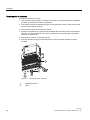
Wiring and assembling ET 200S
1. Wire the ET 200S as shown below:
/
$8;
0
$
$
$8;
1
2
3
①
24 VDC electronic power supply
②
24 VDC sensor supply potential group 1
③
24 VDC load supply potential group 2
1. Use the PROFINET connector to connect the ET 200S (IO device) to the IO controller via
a switch. The PROFINET interface is located on the IM 151-3 PN interface module.
2. Insert the power and electronic modules into the terminal modules.
3. Switch on the power supply for the IO controller.
4. Observe the status LEDs on the IO controller.
CPU 317-2 PN/DP:
– DC 5V → lights up
– SF → off
– BF2 → off
ET 200S
Operating Instructions, 08/2008, A5E00515771-06
33
Brief instructions on commissioning ET 200S
2.2 Commissioning on PROFINET IO
2.2.3
Configuring ET 200S in the SIMATIC manager
Proceed as follows
1. Start SIMATIC Manager and create a new project with an IO controller
(e g., CPU 317-2 PN/DP). For this project, create the OB 1, the OB 82, the OB 83 and the
OB 122.
2. Open the "Properties - Ethernet Interface" window in the HW Config and create a subnet
e. g. Ethernet (1).
3. Take the IM151-3 PN from the ET 200S catalog of the hardware catalog and insert it on
Ethernet(1):PROFINET IO System (100).
4. Drag the individual ET 200S modules from the hardware catalog to the configuration
table.
Table 2- 2
Module
Configuration table in HW Config for PROFINET IO
Order No.:
I address
Q address
Comment
0
6ES7151-3AA20-0AB0 IM151-3 PN
1
6ES7138-4CA01-0AA0 PM-E DC24V
2
6ES7131-4BB01-0AB0 2DI DC24V
0
Bytes 0.0 and 0.1
3
6ES7131-4BB01-0AB0 2DI DC24V
1
Bytes 1.0 and 1.1
4
6ES7131-4BB01-0AB0 2DI DC24V
2
Bytes 2.0 and 2.1
5
6ES7131-4BB01-0AB0 2DI DC24V
3
6
6ES7138-4CA01-0AA0 PM-E DC24V
7
6ES7132-4BB01-0AB0 2DO DC24V
0
Bytes 0.0 and 0.1
8
6ES7132-4BB01-0AB0 2DO DC24V
1
Bytes 1.0 and 1.1
9
6ES7132-4BB01-0AB0 2DO DC24V
2
Bytes 2.0 and 2.1
10
6ES7132-4BB01-0AB0 2DO DC24V
3
Byte 3.0 and 3.1
Power module
Byte 3.0 and 3.1
Power module
1. Set the following parameters:
– In the IO device properties dialog box for the PM-E DC24V, module 1 (in the
configuration table)
Diagnostics: Missing load voltage
– In the IO device properties dialog box for the 2 DO DC24V, Module 7 (in the
configuration table)
Diagnostics: Wire break A0
2. Compile and save the configuration.
34
ET 200S
Operating Instructions, 08/2008, A5E00515771-06
Brief instructions on commissioning ET 200S
2.2 Commissioning on PROFINET IO
2.2.4
Assigning device names for the IO device
Procedure
1. Insert the SIMATIC Micro Memory Card in the IM151-3 PN.
2. Switch on the power supply for the IM151-3 PN.
3. Open the "Properties - IM151-3 PN" window in HW Config and enter the device name for
the IO device there.
4. An online PROFINET connection from the programming device to the IO device via a
switch is required for in order to transfer the name to the IM151-3 PN interface module.
The device name is transferred to the IM151-3 PN using "PLC > Ethernet > Assign
Device Name". To do so, activate the "Assign name" button in the "Assign device name"
window. The device name is stored on the SIMATIC Micro Memory Card in the IM151-3
PN interface module.
Once the name is assigned, it appears in the window.
Alternative procedure:
Alternatively, you can write directly to a SIMATIC Micro Memory Card using a programming
device with an EPROM programming device installed or a PC connected to a SIMATIC USB
EPROM programming device and then use the memory card to transfer the device name to
the IM151-3 PN.
1. Open the "Properties - IM151-3 PN" window in HW Config and enter the device name for
the IO device there.
2. Insert the required SIMATIC Micro Memory Card into the EPROM programming device.
3. Select the IM151-3 PN in HW Config.
4. Select "Target system > Save device name to memory card" in HW Config.
5. Insert the SIMATIC Micro Memory Card written with the device name in the IM151-3 PN.
6. Switch on the power supply for the IM151-3 PN.
The device name is transferred to the IM151-3 PN.
ET 200S
Operating Instructions, 08/2008, A5E00515771-06
35
Brief instructions on commissioning ET 200S
2.2 Commissioning on PROFINET IO
2.2.5
Creating a user program
Proceed as follows
1. Create the user program in the LAD/STL/FBD editor in OB 1.
Example 1: Reading an input and triggering an output:
STL
U I 0.0
If input byte 0.0 and
U M 2.0
memory bit 2.0 is set, then
S O 0.0
set output byte 0.0
Example 2: Transferring an input byte to an output byte:
STL
L PEB 0
Load I/O input byte 0 in the accumulator
T PAB 0
Transfer the accumulator content to
(bytes 0.0 to 0.7)
I/O output byte 0 (bytes 0.0 to 0.7)
1. Save the project in SIMATIC Manager.
2. Download the configuration to the IO controller.
2.2.6
Switching on ET 200S
Procedure
1. Switch on all the power supplies of the ET 200S.
2. Observe the status LEDs on the IO controller, ET 200S, and switch.
– CPU 317-2 PN/DP:
DC 5V: lights up
SF: off
BF2: off
LINK: lights up
– ET 200S:
SF: off
BF: off
ON: lights up
LINK: lights up
– Switch:
LINK: lights up
36
ET 200S
Operating Instructions, 08/2008, A5E00515771-06
Brief instructions on commissioning ET 200S
2.2 Commissioning on PROFINET IO
2.2.7
Evaluating diagnostic messages
Introduction
In this example, you generate alarms by provoking errors on the ET 200S.
In the event of an error, OB 83 is started. Evaluate the start information in OB 83.
Tip: Call up the SFB 52 within the OB 83 and evaluate the E002H diagnostic telegram.
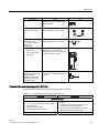
Removing and inserting the 2 DI DC24V HF digital electronic module
1. Remove the 2 DI 24VDC HF electronic module from the terminal module
(e.g., from slot 2) during operation.
2. Monitor the status LEDs on the IM 151-3 PN interface module:
– SF: lights up → there is a diagnostic message.
– BF: off
– ON: lights up
Result: The ET 200S continues to run error-free.
3. In the event of a remove interrupt the OB 83 is started. Start the SFB 52 in OB 83.
Evaluate the E002H diagnostic data record.
You can find information about evaluating the diagnostic data record E002H in the "From
PROFIBUS DP to PROFINET IO
(http://support.automation.siemens.com/WW/view/en/19289930)" programming manual in
the sections "Structure of the configuration data record W#16#E002" and "Blocks of the
diagnostics and configuration records".
4. Reinsert the removed electronic module into the terminal module.
Result:
– Status LEDs on the IM151-3 PN interface module:
SF: off
BF: off
ON: lights up
– Once the module is inserted, diagnostic data record E002H no longer indicates a
discrepancy between the preset and actual configurations for any slot.
ET 200S
Operating Instructions, 08/2008, A5E00515771-06
37
Brief instructions on commissioning ET 200S
2.2 Commissioning on PROFINET IO
2.2.8
Evaluating diagnostic messages
Introduction
In this example, you generate diagnostic messages by provoking errors in the ET 200S.
In the event of an error, OB 83 or OB 82 is started. Evaluate the start information in OB 83.
Tip: Call up the SFB 52 within the OB 83 and evaluate the C00A H diagnostic telegram.
Removal/Insertion Interrupt
1. Remove the 2 DI 24VDC High Feature electronic module from the terminal module
(e.g., from slot 2) during operation.
2. Monitor the status LEDs on the IM 151-3 PN interface module:
– SF: lights up → there is a diagnostic message
– BF: off
– ON: lights up
Result: The ET 200S continues to run error-free.
3. In the event of a remove interrupt the OB 83 is started. Start SFB 52 in OB 1. Evaluate
the E002H diagnostic data record.
You can find information about evaluating the diagnostic data record E002H in the "From
PROFIBUS DP to PROFINET IO
(http://support.automation.siemens.com/WW/view/en/19289930)" programming manual in
the sections "Structure of the configuration data record W#16#E002" and "Blocks of the
diagnostics and configuration records".
4. Reinsert the removed electronic module into the terminal module.
Result:
– Status LEDs on the IM151-3 PN interface module:
SF: off
BF: off
ON: lights up
– Once the module is inserted, diagnostic data record E002H no longer indicates a
discrepancy between the preset and actual configurations for any slot.
38
ET 200S
Operating Instructions, 08/2008, A5E00515771-06
Brief instructions on commissioning ET 200S
2.2 Commissioning on PROFINET IO
Switching off load voltage on the power module
1. Switch off the load voltage on the PM-E DC24V (slot 1).
2. Monitor the status LEDs.
IM151-3 PN:
– SF: lights up
Power module:
– PWR: off → no load voltage available on the power module
– SF: lights up → a diagnostic message is pending.
I/O modules in the voltage group:
– LEDs: light up
3. Evaluate diagnostic data record C00AH.
Tip: Call up the SFB 52 within the OB 1 or OB 82 and evaluate the diagnostic message.
You can find information about evaluating the diagnostic data record C00AH in the "From
PROFIBUS DP to PROFINET IO
(http://support.automation.siemens.com/WW/view/en/19289930)" programming manual in
the section "Structure of diagnostics data records".
4. Switch on the load voltage back on the power module and re-evaluate the diagnostics.
Result:
– Status LEDs on the IM151-3 PN:
SF: off
– Status LEDs on power module:
PWR: on
SF: off
– Status LEDs on I/O modules:
LEDs: off
– The diagnostic message is deleted.
ET 200S
Operating Instructions, 08/2008, A5E00515771-06
39
Brief instructions on commissioning ET 200S
2.2 Commissioning on PROFINET IO
Simulating a wire break in the actuator wiring
1. Remove the cable from terminal 1 on the 2DO DC24V/0.5A HF electronic module (slot 7)
2. Monitor the status LEDs:
IM151-3 PN:
– SF: lights up
Electronic module 2DO DC24V/0.5A HF:
– SF: lights up → there is a diagnostic message
– 1: off → output is not activated
3. Evaluate diagnostic data record C00AH.
You can find information about evaluating the diagnostic data record C00AH in the "From
PROFIBUS DP to PROFINET IO
(http://support.automation.siemens.com/WW/view/en/19289930)" programming manual in
the section "Structure of diagnostics data records".
4. Reattach the cable to the actuator in terminal 1 and reevaluate the diagnostics:
– Status LEDs on the IM151-3 PN:
SF: off
– Status LEDs electronic module 2DO DC24V/0.5 A HF:
SF: off
1: off/on
– The diagnostic message is deleted.
40
ET 200S
Operating Instructions, 08/2008, A5E00515771-06
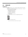
Application planning
3.1
3
Switching on the ET 200S
Simply put your ET 200S together yourself. A configuration tool supports you in doing so.
You can find the tool on the Internet (www.siemens.com/et200).
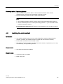
Using power and electronic modules in terminal modules
Various signals are available on the terminals depending on which terminal module is
selected. For more detailed information, refer to the manual for the specific I/O module.
The TM-P and TM-E terminal modules are mixable in the ET 200S configuration.
Usage of COMPACT modules on terminal modules
Various signals are available on the terminals depending on which terminal module is
selected. For more detailed information, refer to the IM 151-1 COMPACT Modules manual.
The terminal module TM-C must always be connected at the start of an ET 200S
configuration. Additional terminal modules TM-E or TM-P are to be connected to the right of
terminal module TM-C.
ET 200S
Operating Instructions, 08/2008, A5E00515771-06
41
Application planning
3.2 Use of the ET 200S in a redundant system
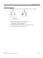
3.2
Use of the ET 200S in a redundant system
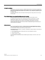
Properties
The ET 200S is integrated in a redundant DP system as DPV0 or DPV1 slave via the Y
switching.
Requirements
DPV0
•
•
•
DPV1
Possible with all interface modules
from STEP 7 V5.3 SP3
GSD file
•
•
IM151-1 HIGH FEATURE
(from 6ES7151-1BA01-0AB0)
from STEP 7 V5.3 SP3
5HGXQGDQW'3V\VWHP
5HGXQGDQW352),%86'3
</,1.
,0
<FRXSOHU
(70
(70
<VXEQHW
(76
Figure 3-1
ET 200S and Y switching
Procedure
1. Configuration of the redundant DP system (redundant DP master, PROFIBUS DP,
slaves)
2. Configure the ET 200S with STEP 7
Reference
42
For additional information see the documentation for the Y-connection (manual or product
information (http://support.automation.siemens.com/WW/view/en/1142696)).
ET 200S
Operating Instructions, 08/2008, A5E00515771-06
Application planning
3.3 Limitation of connectable modules/maximum configuration
3.3
Limitation of connectable modules/maximum configuration
Number of modules
The following modules are available for the ET 200S: interface modules, power modules,
electronic modules, RESERVE modules, technology modules, motor starters, and frequency
converters.
The number of modules you can insert is dependent on the interface module you are using:
● Max. 12 modules with:
– IM151-1 BASIC
– IM151-1 COMPACT
● Max. 63 modules with:
– IM151-1 STANDARD
– IM151-1 FO STANDARD
– IM151-1 HIGH FEATURE
– IM151-3 PN
– IM151-3 PN FO
– IM151-3 PN HIGH FEATURE
Bus length of the ET 200S
A maximum bus length of 2 m can be assigned for the ET 200S.
Deviations are noted in the properties of the interface modules.
Parameter length
● For PROFIBUS DP: Depending on the PROFIBUS DP master you are using
● For PROFINET IO: Not relevant for maximum configuration
Address space
● For PROFIBUS DP: Depending on the PROFIBUS DP master you are using
● For PROFINET IO: Not relevant
ET 200S
Operating Instructions, 08/2008, A5E00515771-06
43
Application planning
3.3 Limitation of connectable modules/maximum configuration
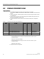
Maximum configuration per potential group
The number of modules that can be connected depends on the total current of all modules in
a potential group. This total current must not exceed the maximum current-carrying capacity
of the power modules or COMPACT modules you are using.
The total current is governed in large part by the digital output modules.
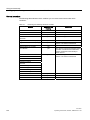
Table 3- 1
Maximum configuration per potential group
Power modules/
COMPACT modules
Maximum current-carrying capacity
Power Module PM-E DC24V
10 A
Power Module PM-E DC24..48V
10 A
Power Module PM-E DC24..48V/AC24..230V
• For 24 to 56.7 VDC
• For 24 to 48/120/230 VAC
10 A
8A
IM151-1 COMPACT
5 A, for I/O modules connected after the IM151-1
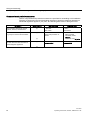
COMPACT
DP master 32-byte diagnostic message frame length
You can use the ET 200S with DP masters with a diagnostic frame length of 32 bytes
because you can set the length of the diagnostic frame in all the interface modules.
Reference
The relevant values can be found in the technical data for the respective modules.
44
ET 200S
Operating Instructions, 08/2008, A5E00515771-06
Application planning
3.4 Application of power modules
3.4
Application of power modules
3.4.1
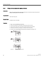
Placing power modules and connecting them to common potential
Placing and connecting to common potential
You can choose where to position the power modules in the ET 200S. Every TM-P terminal
module (for a power module) that you install in the ET 200S opens a new potential group. All
sensor and load supplies of the downstream electronic modules are fed from this TM-P
terminal module (for a power module). If you place an additional TM-P terminal module after
an electronic module/motor starter, you interrupt the potential buses (P1/P2) and
simultaneously open a new potential group. This enables sensor and load supplies to be
individually connected to common potential.
AUX(iliary) bus (AUX1)
A TM-P terminal module (for a power module) allows you to connect additional potential
(up to the maximum rated load voltage of the module), which you can apply by means of the
AUX(iliary) bus.
You can use the AUX(iliary) bus individually:
● As a protective conductor bar
● For additionally required voltage
The AUX1 bus is laid out as follows:
● Maximum current-carrying capacity (at 60°C ambient temperature): 10 A
● Permitted voltage: 230 VAC/DC
ET 200S
Operating Instructions, 08/2008, A5E00515771-06
45
Application planning
3.4 Application of power modules
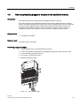
Placing power modules and connecting them to common potential
(0
2
(0
(0
6
(0
2
(0
(0
5
(0
2
(0
1
(0
4
3
7
8
7
9
①
Interface module
⑧
Supply voltage 2
②
Power module
⑨
Supply voltage 3
③
Terminating module
⑩
Protective conductor
④
Potential group 1
⑪
Additionally required voltage
⑤
Potential group 2
⑫
P1/P2 power buses
⑥
Potential group 3
⑬
AUX1 bus
⑦
Supply voltage 1
WARNING
If you connect the AUX1 bus to common potential independently of the P1/P2 buses
(different voltages), there is no safe electrical separation (in accordance with EN 50178)
between the AUX1 bus and the P1/P2 buses.
Connecting different potentials to the AUX1 bus
Note
If you apply different potentials to the AUX1 bus within an ET 200S station, you must
separate the potential groups by means of a power module with the TM-P15S23-A0 terminal
module.
46
ET 200S
Operating Instructions, 08/2008, A5E00515771-06
Application planning
3.4 Application of power modules
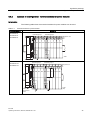
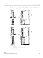
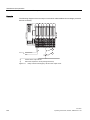
3.4.2
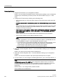
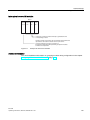
Example of a configuration: Terminal modules for power modules
Introduction
The following table shows how terminal modules for power modules can be used:
Table 3- 2
Terminal modules for power modules
Terminal module
Structure
TM-P15S22-01
TM-P15C22-01
3RWHQWLDOJURXS
3RWHQWLDOJURXS
%DFNSODQHEXV
3
3
TM-P15N22-01
30 (0 (0 (0 30 (0 (0 (0 (0 (0
$8;
TM-P15S23-A1
TM-P15C23-A1
3RWHQWLDOJURXS
3RWHQWLDOJURXS
%DFNSODQHEXV
3
3
TM-P15N23-A1
30 (0 (0 (0 30 (0 (0 (0 (0 (0
$ $
$ $
$FFHVVYLD
WHUPLQDOVRQ
$8;
ET 200S
Operating Instructions, 08/2008, A5E00515771-06
$8;
3(
47
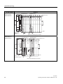
Application planning
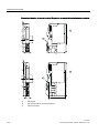
3.4 Application of power modules
Terminal module
Structure
TM-P15S23-A0
TM-P15C23-A0
3RWHQWLDOJURXS
3RWHQWLDOJURXS
%DFNSODQHEXV
3
3
TM-P15N23-A0
30 (0 (0 (0 30 (0 (0 (0 (0 (0
$ $
$ $
$8;
$FFHVVYLD
WHUPLQDOVRQ
$8;
2SHQQHZSRWHQWLDOJURXSYLD$8;
TM-P30S44-A0
TM-P30C44-A0
3RWHQWLDOJURXS
30
(0
3RWHQWLDOJURXS
30
$ $
$ $
%DFNSODQHEXV
3
3
(0
$8;
$FFHVVYLD
WHUPLQDOVWR$8;
2SHQQHZSRWHQWLDOJURXSYLD$8;
48
ET 200S
Operating Instructions, 08/2008, A5E00515771-06
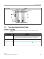
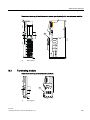
Application planning
3.4 Application of power modules
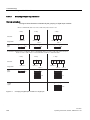
Terminal module
Structure
TM-PF30S47-F1
3RWHQWLDOJURXS
30
(0
3RWHQWLDOJURXS
30
%DFNSODQHEXV
3
3
(0
$8;
3.4.3
Finding the correct power module for an I/O device
Applicability of power modules
The following table describes which power modules you can use with the different I/O
modules:
Power modules
I/O modules
PM-E DC24V
Can be used for all electronic modules that require a maximum load voltage of 24 VDC.
PM-E DC24..48V
Applicable
• Can be used for all electronic modules that require a maximum load voltage of 24 VDC.
• For UC electronic modules if the maximum load voltage is 48 VDC and AC is not
required.
PM-E DC24..48V/
AC24..230V
Can be used with all electronic modules.
PM-E F pm DC24V
PROFIsafe
See "ET 200S Distributed I/O System - Fail-Safe Modules
(http://support.automation.siemens.com/WW/view/en/12490437)" Manual, Chapter
"Assigning Modules of an ET 200S"
PM-E F pp DC24V
PROFIsafe
PM-E F DC24V PROFIsafe
ET 200S
Operating Instructions, 08/2008, A5E00515771-06
49
Application planning
3.4 Application of power modules
Power modules
PM-D
I/O modules
For motor starters and frequency converters.
See "ET 200S Motor Starters
(http://support.automation.siemens.com/WW/view/en/6008567)" Manual or "Frequency
Converter ET 200S FC (http://support.automation.siemens.com/WW/view/en/26291825)"
Operating Instructions
PM-D F
For fail-safe applications with motor starter or frequency converter.
See "ET 200S Motor Starters
(http://support.automation.siemens.com/WW/view/en/6008567)" Manual or "Frequency
Converter ET 200S FC (http://support.automation.siemens.com/WW/view/en/26291825)"
Operating Instructions
50
ET 200S
Operating Instructions, 08/2008, A5E00515771-06
4
Installing
4.1
Basic principles of installation
WARNING
Open components
Modules of an ET 200S are open components. This means that you may only install the
ET 200S in cases, cabinets or electrical plant rooms where they will only be accessible with
a key or a tool. Only trained or authorized personnel are allowed access to such cubicles,
cabinets or electrical operating rooms.
Simple installation
The ET 200S distributed I/O system is designed for simple installation.
Installation rules
● The ET 200S distributed I/O system starts
– with an interface module or
– with a TM-C terminal module with COMPACT module.
● A power module comes after the interface module or at the beginning of each potential
group.
● After a power module come digital, analog, technological, or RESERVE modules.
● After a COMPACT module, digital, analog, technological, or RESERVE modules may
follow. If necessary, power modules may also be deployed.
● The ET 200S distributed I/O system ends with the terminating module.
● The maximum configuration of the distributed I/O system is dependent on the interface
modules being used.
Installation position
Preferably, the ET 200S is mounted horizontally on a vertical wall. All other positions are
possible, although there are certain restrictions regarding the ambient temperature.
ET 200S
Operating Instructions, 08/2008, A5E00515771-06
51
Installing
4.1 Basic principles of installation
Mounting rail
The ET 200S distributed I/O system is installed on a mounting rail according to EN 60715
(35 x 7.5 mm or 35 x 15 mm).
Appropriate surface designs are:
● Steel strip according to Appendix A of EN 60715, or
● Tinned steel strip. We recommend the following mounting rails for this purpose:
– 6ES5710-8MA11 (length: 483 mm)
– 6ES5710-8MA21 (length: 530 mm)
– 6ES5710-8MA31 (length: 830 mm)
– 6ES5710-8MA41 (length: 2000 mm)
Note
If you use mounting rails from other manufacturers, please check whether they have
the required properties for your climatic ambient conditions.
Note
If the ET 200S distributed IO device is exposed to increased vibrations and shock, we
recommend that you screw the mounting rail to the mounting surface at intervals of
200 mm.
To prevent the ET 200S distributed I/O system from slipping sideways, we
recommend that you apply a mechanical hold-down (e.g. with grounding terminal,
8WA2011-1PH20) at both ends of the device.
If you install the rail on grounded, zinc-plated mounting plates, there is no need to
ground the rail separately.
52
ET 200S
Operating Instructions, 08/2008, A5E00515771-06
Installing
4.1 Basic principles of installation
Minimum clearances for installation, wiring, and ventilation
When installing the ET 200S in a housing, ensure that the distance to the lid of the housing
or the front door is at least 1 mm.
PP
30 (0 (0 (0 30
(0 (0 (0
PP
PP
PP
PP
Figure 4-1
PP
PP
Minimum clearances
ET 200S
Operating Instructions, 08/2008, A5E00515771-06
53
Installing
4.2 Installing the interface module
4.2
Installing the interface module
Introduction
● The interface module connects the ET 200S with the PROFIBUS DP and PROFINET.
● The interface module transfers data between the higher-level controller and the I/O
modules.
Requirements
● The DIN rail is installed.
● All terminal modules are installed to the right of the interface module. The maximum
configuration of the ET 200S distributed I/O system is 12/63 I/O modules.
Required tools
Screwdriver with 3 mm blade
Installing the interface module
1. Hang the interface module on the rail.
2. Tip the interface module back until you hear the slider engage.
1
2
Figure 4-2
Installing the interface module
Removing the interface module
The interface module is wired, and the terminal modules are on the right:
1. Switch off the supply voltage on the interface module.
2. Disconnect the wiring and the bus connector on the interface module.
3. Use a screwdriver to push the slider on the interface module down until the mechanism
stops and move the interface module to the left.
Note: The locking mechanism is beneath the interface module.
4. Press down on the slider while taking the interface module off the mounting rail.
54
ET 200S
Operating Instructions, 08/2008, A5E00515771-06
Installing
4.3 Installing the TM-P and TM-E terminal modules
4.3
Installing the TM-P and TM-E terminal modules
Introduction
● The terminal modules serve to receive the I/O modules and power modules.
● The terminal modules can be wired (without I/O modules)
● All the terminal modules must be installed to the right of the interface module.
Requirements
● The DIN rail is installed.
Required tools
Screwdriver with 3 mm blade
Installing the terminal module
1. Fit the terminal module onto the rail.
2. Move terminal module backward until the slider can be heard locking in place.
3. Move the terminal module to the left until you hear it snap into place at the previous
interface module (if already installed) or the terminal module.
1
3
2
Figure 4-3
Installing the terminal module
ET 200S
Operating Instructions, 08/2008, A5E00515771-06
55
Installing
4.3 Installing the TM-P and TM-E terminal modules
Removing the terminal module
The terminal module is wired, and there are other terminal modules on the right and left.
A terminal module in the ET 200S distributed I/O system can only be removed when there is
a clearance of approx. 8 mm to the adjacent terminal modules (you achieve this clearance
by moving the adjacent modules).
1. Switch off the supply voltage on the terminal module and, if applicable, the power
module.
2. Disconnect the wiring on the terminal module.
3. Removing the terminal module (from the right):
Use a screwdriver to press down the slider on the previous (left hand) terminal module /
interface module until the mechanism stops then move the interface module to the right.
Removing the terminal module (from the right):
Use a screwdriver to press down the slider on the interface module until the mechanism
stops then move the interface module to the left.
Note: The slider is located underneath the terminal module.
4. Press down on the slider while taking the terminal module off the mounting rail.
3
3
4
1
Figure 4-4
①
Removing the terminal module (from the right)
Slide
Note
It is not necessary to remove the terminal module in order to replace the terminal box.
56
ET 200S
Operating Instructions, 08/2008, A5E00515771-06
Installing
4.4 Installing the terminal modules TM-C for COMPACT modules
4.4
Installing the terminal modules TM-C for COMPACT modules
Introduction
● The terminal modules serve to receive COMPACT modules.
● The terminal modules can be prewired (without COMPACT modules).
● All other terminal modules are installed to the right of the terminal module for COMPACT
modules.
Requirements
● The mounting rail is installed.
Required tools
Screwdriver with 3 mm blade
Mounting a terminal module for COMPACT modules
1. Insert the terminal module for COMPACT modules in the mounting rail (on the left side).
2. Move terminal module backward until the slider can be heard locking in place.
Figure 4-5
Mounting a terminal module for COMPACT modules
ET 200S
Operating Instructions, 08/2008, A5E00515771-06
57
Installing
4.4 Installing the terminal modules TM-C for COMPACT modules
Removing a terminal module for COMPACT modules
The terminal module is wired, and there are other terminal modules to the right.
The terminal module for COMPACT modules can only be removed when there is
approximately 8 mm space between it and the next terminal module (shift the modules if
necessary).
1. Switch off the supply voltage on the terminal module for COMPACT modules or for the
power module, if applicable.
2. Disconnect the wiring on the terminal module for COMPACT modules.
3. Use a screwdriver to press down the slider on the interface module for COMPACT
modules until the mechanism stops, then move the terminal module to the left.
Note:
– The slider is located underneath the terminal module.
– This step is not required if no other terminal modules are located to the right of the
terminal module for COMPACT modules.
4. Press down on the slider while taking the terminal module off the mounting rail.
Figure 4-6
①
Removing a terminal module for COMPACT modules
Slide
Note
The terminal box can be replaced without first removing the terminal module for COMPACT
modules.
58
ET 200S
Operating Instructions, 08/2008, A5E00515771-06
Installing
4.5 Installing add-on terminals
4.5
Installing add-on terminals
Introduction
● The add-on terminals expand the function of the terminal modules for ET 200S.
Extra potentials can be applied to the add-on terminal as necessary
(for example to connect encoders and actuators using 3- and 4- conductor technology
with IM151-1 COMPACT).
The add-on terminal can be cascaded if extra potentials are required.
● Terminal modules and add-on terminal can be prewired (without COMPACT modules or
I/O modules).
● Various voltage groups can be configured on the add-on terminal using pluggable
bridges.
Requirements
● The mounting rail is installed.
● The terminal module for COMPACT modules is installed or the terminal modules TM-P
and TM-E are installed at a width of 120 mm.
Note
Requirements for installing the add-on terminals under terminal modules TM-P and TM-E
Both of the "outside" terminal modules must have the same height. No higher terminal
modules are allowed to mounted between both of these terminal modules.
Required tools
4-mm screwdriver
ET 200S
Operating Instructions, 08/2008, A5E00515771-06
59
Installing
4.5 Installing add-on terminals
Installing add-on terminals
1. Slide the add-on terminal from below onto the terminal module for COMPACTmodules or
the TM-P and TM-E terminal modules.
Figure 4-7
①
60
Installing add-on terminals
Catch
ET 200S
Operating Instructions, 08/2008, A5E00515771-06
Installing
4.5 Installing add-on terminals
If your ET 200S modules are exposed to shocks or vibrations they can be stabilized by using
the mounting brackets included in the delivery package.
1. Slide the fixing bracket into the slot in the underside of the additional terminal.
2. Screw the fixing bracket firmly onto the base.
The lower part of the mounting bracket can be broken off and used to fill any gap
between the add-on terminal and its base by placement under the bracket (as a spacer).
Figure 4-8
Stabilizing an add-on terminal with fixing bracket
①
Mounting brackets
②
Spacer
ET 200S
Operating Instructions, 08/2008, A5E00515771-06
61
Installing
4.5 Installing add-on terminals
Removing add-on terminals
The add-on terminal is wired up.
1. Switch off the supply voltage on the add-on terminal, the terminal module for COMPACT
modules, and the power module, if applicable.
2. If the add-on terminal is stabilized using a mounting bracket, loosen it from the base and
pull it out of the add-on terminal.
3. Disconnect the wiring on the add-on terminal.
4. Push the screwdriver in the right hand slot between the terminal module and the add-on
terminal. Turn the screwdriver. The catch is released from its bracing when the add-on
terminal is pushed away.
5. Repeat this procedure on the left-hand slot.
6. Then pull the add-on terminal downwards and out of the terminal module / terminal
modules.
Figure 4-9
62
Removing add-on terminals
①
Mounting brackets
②
Catch
ET 200S
Operating Instructions, 08/2008, A5E00515771-06
Installing
4.6 Removing/installing pluggable bridges on the additional terminal
4.6
Removing/installing pluggable bridges on the additional terminal
Introduction
The additional terminal is fitted with three pluggable bridges on delivery.
All of the terminals on the additional terminal have the same potential with the 3 plugged
bridges. If additional potentials are required then various potential groups can be configured
by removing the pluggable bridges. Detailed information pertaining to the expansion of
potential groups can be found in the device manual in the chapter Terminal modules >
Additional terminals TE-U120S4x10 and TE-U120C4x10 (6ES7193-4FLx0-0AA0).
Requirements
● The DIN rail is installed.
Required tools
Screwdriver with 3 mm blade
Removing pluggable bridges
1. Pull the labeling strips out of the additional terminals.
2. Insert the screwdriver underneath the pluggable bridge being removed from the side.
3. Loosen the bridge and then pull it out.
4. If necessary, repeat steps 2 and 3.
5. Reinsert the labeling strips.
Figure 4-10
Removing the bridges
ET 200S
Operating Instructions, 08/2008, A5E00515771-06
63
Installing
4.7 Replacing the terminal box on the terminal module
Installing pluggable bridges
1. Pull the labeling strips out of the additional terminals.
2. Insert the pluggable bridge between the potential groups being connected.
3. If necessary, repeat step 2.
4. Reinsert the labeling strips.
The inserted bridges can be recognized by their labeling strips.
4.7
Replacing the terminal box on the terminal module
Introduction
The terminal box is part of the terminal module. If necessary, you can replace the terminal
box. It is not necessary to remove the terminal module.
Requirements
● The terminal module is installed, wired, and fitted with a COMPACTmodule, power
module, or electronic module.
Required tools
Screwdriver with 3 mm blade
64
ET 200S
Operating Instructions, 08/2008, A5E00515771-06
Installing
4.7 Replacing the terminal box on the terminal module
Proceed as follows
1. Switch off the supply voltage on the terminal module and, if applicable, the power
module.
2. Disconnect the wiring on the terminal module.
3. Simultaneously press
– the upper and lower release buttons of the electronic module or power module, and
remove it from the terminal module.
– The release button located above of the COMPACT module and pull it out of the
terminal module.
4. Push the screwdriver at an angle from below into the small opening underneath the slot
number. At the same time pull the terminal box downward until it stops. Then pull the
terminal box upward and out of the terminal module.
5. Replace the terminal box, and insert the new one into the terminal module from above
(see figure). Then push the terminal box upward until it snaps into place.
6. Insert the COMPACTmodule, power module or electronic module into the terminal
module.
7. Wire the terminal module.
8. Switch on the supply voltage on the terminal module and, if applicable, the power
module.
1
4
4
①
Slot number label
Figure 4-11 Replacing the terminal box on the terminal module
ET 200S
Operating Instructions, 08/2008, A5E00515771-06
65
Installing
4.8 Installing the bus terminating module
4.8
Installing the bus terminating module
Introduction
The terminating module on the right end of the ET 200S terminates the ET 200S distributed
I/O system. If you have not inserted a terminating module, the ET 200S is not ready for
operation.
Requirements
The last terminal module must be installed.
Installing the bus terminating module
1. Fit the bus termination module onto the rail to the right of the last terminal module.
2. Pivot the terminating module backwards onto the DIN rail.
3. Push the bus termination module to the left until you hear it lock into the last terminal
module.
1
3
2
Figure 4-12
66
Installing the bus terminating module
ET 200S
Operating Instructions, 08/2008, A5E00515771-06
Installing
4.9 Installing the shield contact
Removing the Bus Terminating Module
1. Use a screwdriver to push the slider on the last terminal module down until the
mechanism stops, and move the terminating module to the right.
2. Pivot the terminating module so that it comes off the DIN rail.
Note
If
• the terminating module of the ET 200S is removed and remounted under voltage, or
• the ET 200S backplane bus is interrupted during operation, e. g. at a terminal module,
and then restored to function,
the complete power supply of the ET 200S must be switched off and on again in order to
achieve a defined station status.
4.9
Installing the shield contact
Introduction
● You need the shield contact to connect cable shields (for example, analog electronic
modules, 1COUNT 24V/100kHz electronic module and 1SSI electronic module).
● Fit the shield connection on the terminal module.
● The shield connection consists of a shield connection element, a power bus (3 x 10 mm),
a shield clamp, and a grounding terminal.
Requirements
● The terminal modules are installed.
Required tools
● Screwdriver with 3 mm blade
● Metal-cutting saw
ET 200S
Operating Instructions, 08/2008, A5E00515771-06
67
Installing
4.9 Installing the shield contact
Proceed as follows
1. Push the shield connection element onto the first terminal module from below.
2. Push the shield connection element onto the last terminal module from below.
In order to achieve stability of the busbar between two shield contact elements during
installation, you must connect an additional shield contact element after every sixth
terminal module (given a width of 15 mm).
3. Saw off the correct length from the busbar. The length of the busbar is: equal to the
distance between the shield connection elements + 45 mm.
4. Push the busbar into the shield contact element. The busbar must protrude from the
shield contact element by 15 mm on the left or right after installation.
5. Attach the shield terminals to the busbar (between the shield connection elements).
6. Attach the ground connection terminal to the protruding busbar.
1
4
2
3
Figure 4-13
68
Installing the shield contact
①
Shielding terminals
②
shield connection elements
③
Ground connection terminal
④
Power bus
ET 200S
Operating Instructions, 08/2008, A5E00515771-06
Installing
4.10 Applying slot number labels and color identification labels
4.10
Applying slot number labels and color identification labels
Introduction
● The slot number labels identify the individual I/O modules with a slot (1 to 63).
● The color identification labels permit individual color coding of the terminals in
accordance with company or national conventions. The color identification labels are
available in white, red, blue, brown, yellow, yellow-green, and turquoise. Each terminal on
the terminal module can be fitted with a color identification label.
● The slot number labels and color identification labels are applied onto the terminal
modules.
– Position of the slot number plate: below the coding element on the terminal module.
– Position of the color-coding plates: directly next to each terminal on the terminal box.
Requirements
● The terminal modules are installed.
● You can only fit the slot number labels when no electronics modules are installed.
● The terminal modules should not be wired when you apply the color identification labels.
Required tools
3 mm screwdriver (for removal only)
ET 200S
Operating Instructions, 08/2008, A5E00515771-06
69
Installing
4.10 Applying slot number labels and color identification labels
Applying slot number labels and color identification labels
Applying slot number plates:
1. Break the slot number label (1 to 63) off the strip.
2. Use your finger to press the slot number label onto the terminal module.
Applying color-coding plates:
1. You can place the color identification labels in the opening next to the terminal while they
are still on the strip and then bend the strip back to pull them off.
2. Use your finger to press the color identification labels onto the terminal module.
1
2
2
2
Figure 4-14
2
Applying slot number labels and color identification labels
①
Slot number label
②
Color identification labels
Removing slot number labels and color identification labels
Removing slot number plates:
1. Remove the electronic module from the terminal module.
2. Lever the slot number label out of its mount.
Removing color-coding plates:
Use a screwdriver to lever the color-coding plates from their mounts.
70
ET 200S
Operating Instructions, 08/2008, A5E00515771-06
Installing
4.11 Mounting Color Identification Labels for ET 200S and ET 200S COMPACT
4.11
Mounting Color Identification Labels for ET 200S and ET 200S
COMPACT
Properties
● Color-coded labels allow terminals to be identified in the colors white, red, blue, yellow,
yellow-green, and turquoise.
● Color-coded labels can be used at the terminal modules TM-E, TM-P and TM-C of the
ET 200S and ET 200S COMPACT.
● The packaging unit encompasses 200 color-coded labels (10 star-shaped mounts with 20
piece each).
Introduction
You can provide every terminal at a terminal module with a color-coded label. The colorcoded labels are mounted on the terminal module. Color-coded labels are positioned directly
next to the terminal.
Requirement
The terminal module should not be wired in order to make mounting of the color-coded
labels easier.
Required tools
Screwdriver with 3.5 mm blade
ET 200S
Operating Instructions, 08/2008, A5E00515771-06
71
Installing
4.11 Mounting Color Identification Labels for ET 200S and ET 200S COMPACT
Mounting Color-Coded Labels
1. Press the point of the color-coded label using the screwdriver into the provided opening
of the terminal module.
2. Hold the color-coded label during the following steps.
3. Bend the star-shaped mount upwards by approx. 30° to 40°.
4. Detach the color-coded label from the mount by moving the mount back and forth
sideways.
Figure 4-15
Mounting Color-Coded Labels
Removing Color-Coded Labels
Use a screwdriver to lever the color-coded labels from their mounts.
Note
Ensure that the color-coded labels do not fall into the terminal openings. Color-coded labels
can only be removed from terminal openings after the COMPACT module has been
dismantled.
72
ET 200S
Operating Instructions, 08/2008, A5E00515771-06
5
Wiring and assembly
5.1
General rules and regulations for operating the ET 200S
Introduction
When operating the ET 200S distributed I/O system as part of a plant or system, special
rules and regulations have to be followed depending on the field of application.
This chapter provides an overview of the most important rules you must observe when
integrating the ET 200S distributed I/O system into a plant or system.
Specific application
Please observe the safety and accident prevention regulations applying to specific
applications (e.g. machine protection guidelines).
EMERGENCY-STOP devices
EMERGENCY-STOP devices according to IEC 204 (coincides with VDE 113) must remain
effective during all operating modes of the plant or system.
System Startup after Certain Events
The table below shows what you have to observe when restarting a plant after specific
events.
If there is ...
Start-up following a power drop or failure
Startup of the ET 200S follows an
interruption of the bus communication
Startup follows unlocking of the emergency
stop device
ET 200S
Operating Instructions, 08/2008, A5E00515771-06
then ...
No dangerous operating states may occur. If
necessary actuate an EMERGENCY-STOP!
There must not be an uncontrolled or undefined
startup.
73
Wiring and assembly
5.1 General rules and regulations for operating the ET 200S
Line voltage
The table below shows what must be monitored respecting supply voltage.
With ...
the ...
Stationary plants or systems without all-pole line
voltage disconnect switch
building installation must contain a mains
disconnect switch or a fuse.
load power supplies, power supply modules
the set rated voltage range must match the local
supply voltage.
All circuits of the ET 200S distributed I/O system
Any fluctuation/deviation in the supply voltage
from the rated value must be within the permitted
tolerance.
24 VDC supply
The table below shows what must be monitored for 24 VDC power supply.
With ...
you need to observe ...
Buildings
External lightning
protection
Take lightning protection
precautions
24 VDC power supply cables, signal
cables
internal lightning
protection
(for example, lightning protection
elements)
24 VDC supply
Safe (electrical) isolation of extra-low voltage
Protection against outside electrical influences
The table below shows how you must protect your system against electrical interference or
faults.
With ...
Make sure that ...
all plants or systems in which the ET 200S
is integrated,
The plant or system is connected to a protective
conductor for diverting electromagnetic interference.
power supply, signal, and bus cables
the cable routing and installation is correct.
Signal and bus cables
A cable or wire break cannot lead to undefined states
in the plant or system.
See also
Mechanical and Climatic Ambient Conditions (Page 133)
74
ET 200S
Operating Instructions, 08/2008, A5E00515771-06
Wiring and assembly
5.2 Operating the ET 200S on a grounded incoming supply
5.2
Operating the ET 200S on a grounded incoming supply
Introduction
In this section, you will find information on the overall configuration of an ET 200S distributed
I/O system on a grounded incoming supply (TN-S system). The specific subjects discussed
are:
● Disconnecting devices, short-circuit and overload protection to VDE 0100 and VDE 0113
● Load voltage supplies and load circuits.
Grounded incoming supply
In grounded incoming supplies, the neutral conductor of the supply line is grounded. A single
fault between a live conductor and ground or a grounded part of the installation results in
tripping of the protective devices.
Safety isolation
Safe electrical isolation must be provided for:
● Modules that require supply with voltages ≤ 60 VDC or ≤ 25 VAC.
● 24 VDC load circuits
Configuring the ET 200S with ungrounded reference potential
As of IM151-1 BASIC (6ES7151-1CA00-0AB0), IM151-1 STANDARD (6ES7151-1AA020AB0), IM151-1 FO STANDARD (6ES7151-1AB01-0AB0), IM151-1 HIGH FEATURE
(6ES7151-1BA00-0AB0), IM151-3 PN, IM151-3 PN HIGH FEATURE and IM151-1
COMPACT, the ground M of the nominal supply voltage of the IM151-x is connected to the
mounting rail (grounding conductor) via an RC combination, thus making a ground-free
installation is possible.
To divert interference current, the reference potential of the IM151-x is connected internally
to the mounting rail (protective conductor) via an RC combination (R = 10 MΩ / C = 22 nF).
High-frequency interference currents are thus discharged, and static charge is prevented.
ET 200S
Operating Instructions, 08/2008, A5E00515771-06
75
Wiring and assembly
5.2 Operating the ET 200S on a grounded incoming supply
Components and protective measures
Various components and protective measures are specified for assembling a full installation.
The type of components and and the binding character of protective measures depends on
which DIN regulation applies to your plant. The following table refers to the figure below.
Compare ...
Refer to figure
Disconnection element for control
system, sensors, and actuators
①
Short-circuit / overload protection:
②
In groups for sensors and actuators
DIN VDE 0100
... Part 460:
... Part 1:
Main switch
Disconnector
... Part 725:
Single-pole protection of
circuits
... Part 1:
• With grounded
secondary circuit:
unipolar
• otherwise: fuse all poles
Isolation by transformer
recommended
Isolation by transformer
recommended
③
Load current PS for AC power
circuits with more than five items of
electromagnetic apparatus
76
②
DIN VDE 0113
③
ET 200S
Operating Instructions, 08/2008, A5E00515771-06
Wiring and assembly
5.2 Operating the ET 200S on a grounded incoming supply
ET 200S in the overall configuration
The figure below shows the ET 200S distributed I/O system in the overall configuration (load
voltage supply and grounding concept) with incoming supply from a TN-S system.
L1
L2
L3
N
PE
Low voltage distribution e.g.
TN-S system (3 x 400 V)
FE: Functional earth for direct diversion
of interference levels to the mounting rail via
spring contact
ET 200S
1
FE
FE FE
FE FE
FE FE
FE
Mounting rail
2
PE (AUX1)
AC
DC
1L+
1M
Shield support for supporting
cable shields
Ground bus
2
Load circuit
400 VAC for motor starters
2
3
AC
DC
Load circuit 24 VDC for electronic modules and
motor starters
2
3
AC
AC
Load circuit 120 VAC / 230 VAC for AC modules
Figure 5-1
Operation of ET 200S with grounded reference potential
ET 200S
Operating Instructions, 08/2008, A5E00515771-06
77
Wiring and assembly
5.3 Electrical configuration of the ET 200S
5.3
Electrical configuration of the ET 200S
Galvanic isolation
In the ET 200S, isolation exists between:
● The load circuits/process and all other circuit components of the ET 200S
● The PROFIBUS DP interface in the interface module and all other circuit components
● The PROFINET interface in the IM151-3 PN interface module and all other circuit
components
The figure below shows the voltage ratios for ET 200S with IM151-1. Only the primary
components are shown in the figure.
(OHFWURQLFV
%DFNSODQHEXV
(76EDFNSODQHEXV
%XV
LQWHUIDFH
0RXQWLQJ
UDLO
(OHFWULFDO
LVRODWLRQ
(OHFWULFDO
LVRODWLRQ
,0
,0
,0
/
/ /
0
0
9'& 0 3(
3RZHU PRGXOH
%XV
LQWHUIDFH
(OHFWULFDO
LVRODWLRQ
%XV
LQWHUIDFH
%XV
LQWHUIDFH
(OHFWULFDO
LVRODWLRQ
(OHFWULFDO
LVRODWLRQ
3URFHVV
HOHFWURQLFV
3URFHVV
HOHFWURQLFV
(OHFWURQLF
PRGXOH
(OHFWURQLF
PRGXOH
%XV
LQWHUIDFH
(OHFWULFDO
LVRODWLRQ
3URFHVV
HOHFWURQLFV
9'& 0 3(
3RZHU
PRGXOH
7HUPLQDWLQJPRGXOH
'3
,QWHU
IDFH
(OHFWURQLF
PRGXOH
'3LQWHUIDFHSRWHQWLDO
3RWHQWLDO,2
Figure 5-2
78
3RWHQWLDOORJLFFLUFXLWU\
Potentials of the ET 200S with IM151-1
ET 200S
Operating Instructions, 08/2008, A5E00515771-06
Wiring and assembly
5.4 Wiring the ET 200S
5.4
Wiring the ET 200S
5.4.1
Wiring rules for the ET 200S
Wiring rules
Wiring Rules for...
Interface module
(supply voltage)
Terminal modules (spring
and screw terminals)
Terminal modules
(Fast Connect)
connectable cable cross sections for solid
cables
No
0.14 mm to 2,5 mm2
0.5 mm to 1.5 mm2
permitted crosssections of flexible
conductors
0.25 mm to 2.5 mm2
0.25 mm to 1.5 mm2
0.14 mm to 2,5 mm2
0.14 mm to 1.5 mm2
0.5 mm to 1.5 mm2
---
without wire end ferrule
with wire end ferrule
Number of wires per connection
1 or combination of 2 cables up to 1,5 mm2 (total)
in a mutual wire end ferrule
1
Maximum external diameter of the wire
insulation
∅ 3.8 mm
∅ 3.1 mm at 1.5 mm2
∅ 3.8 mm at 2.5 mm2
∅ 3.2 mm at 1.5 mm2
Stripping length of the wires
Wire-end ferrules
Without insulating collar
to DIN 46228
with insulating collar
0.25 to 1.5 mm2
11 mm
Form A, 8 to 12 mm
long
--Form A, up to 12 mm long ---
5.4.2
Form E, up to 12 mm long
---
Wiring a terminal module with screw-type terminals
Introduction
Requirements
In terminal modules with screw-type terminals, the individual wires are screwed into the
terminal.
● Adhere to the wiring rules.
● No wire end ferrules required
Required tools
Screwdriver with 3 mm blade
Proceed as follows
1. Strip 11 mm of insulation from the wires.
2. Insert the wires into the terminal.
3. Screw the ends of the individual wires onto the terminal module (torque of 0.4 to 0.7 Nm).
ET 200S
Operating Instructions, 08/2008, A5E00515771-06
79
Wiring and assembly
5.4 Wiring the ET 200S
5.4.3
Wiring a Terminal Module with Spring Terminals
Introduction
When wiring terminal modules with spring terminals, the wires are secured in the terminal
simply by inserting them into the terminal.
Requirements
Follow the wiring rules.
Required tools
Screwdriver with 3 mm blade
Procedure
1. Strip 11 mm of insulation from the wires.
2. Insert the screwdriver in the upper (round) opening of the terminal.
3. Insert the wire until it stops in the lower (square) opening of the terminal.
4. Release the terminal by pushing the screwdriver into the opening.
5. Push the wire into the released spring terminal, and pull the screwdriver out.
Figure 5-3
80
Wiring with Spring Terminals
ET 200S
Operating Instructions, 08/2008, A5E00515771-06
Wiring and assembly
5.4 Wiring the ET 200S
5.4.4
Wiring terminal modules with Fast Connect
Introduction
● In the case of terminal modules with Fast Connect, the individual wires are attached
using a quick connection method that requires no stripping.
● Fast Connect is a connection method that requires no conductor preparation
(i. e., the conductor insulation does not have to be stripped).
● Each terminal of the terminal module with Fast Connect has a test opening
(e.g. for measuring the voltage). The test opening is suitable for test probes with a
maximum diameter of Ø 1.5 mm.
● Wire end ferrules are not permitted.
● Diagram of the Fast Connect terminal module
1
2
3
4
①
Opening for measuring and testing: max. Ø 1.5 mm
②
Opening for 1 conductor: 0.5 ... 1.5 mm2
③
Slider open (the cable can be inserted)
④
Locking mechanism closed (the wire is connected)
Requirements
● Follow the wiring rules.
Required tools
Screwdriver with 3 mm blade
ET 200S
Operating Instructions, 08/2008, A5E00515771-06
81
Wiring and assembly
5.4 Wiring the ET 200S
Connectable wires
You can connect solid and flexible conductors with PVC insulation with a wire cross-section
between 0.5 mm2 and 1.5 mm2 (max. external diameter 3.2 mm). If the cross-section of the
conductors is the same they can be wired fifty times. A list of the tested conductors can be
found on the Internet (http://www.idc2.com).
UL-compliant cables and connections
Wiring range for insulating piercing connection 22-16 AWG solid/stranded PVC insulated
conductors, UL style no. 1015 only.
Proceed as follows
1. Insert the unstripped cable in the round opening until it stops (the insulation and
conductor must form a flat surface).
2. Insert the screwdriver into the opening above the slider until it stops.
3. Press the screw driver downwards until the slider reaches the end position.
PP
Figure 5-4
Wiring terminal modules with Fast Connect
Result: The wire is connected.
Note
If you would like to reuse a conductor after it was already connected once then it must be
recut.
82
ET 200S
Operating Instructions, 08/2008, A5E00515771-06
Wiring and assembly
5.4 Wiring the ET 200S
Release the wiring from the terminal module with Fast Connect
1. Insert the screwdriver into the opening below the slider until it stops.
2. Use the screwdriver to lever and push the slider upwards.
3. The wiring is disconnected: Remove the wire.
Figure 5-5
Release the wiring from the terminal module with Fast Connect
Removing any conductor remnants (if necessary)
To remove any remains of the conductor (insulation), you can deinstall the slider from the
terminal module (see Step 3). To do this, the slider must be open (upper position). You can
only insert the slider in the upper position (see Step 4).
1. Insert the screwdriver in the opening below the slider (the tip of the screwdriver is on the
lip of the slider).
2. Press the screwdriver downwards to lever the slider out of the terminal module.
3. Remove the locking mechanism from the terminal module. Remove any remnants of the
conductor from the locking mechanism.
4. Use your fingers to press the slider back into the opening. Caution: Make sure the slider
is inserted in the correct position otherwise you can damage the clamping point.
Figure 5-6
Deinstalling the slider from the terminal module
ET 200S
Operating Instructions, 08/2008, A5E00515771-06
83
Wiring and assembly
5.4 Wiring the ET 200S
5.4.5
Wiring terminal modules
Introduction
The ET 200S distributed I/O system incorporates terminal modules for power modules,
electronic modules and COMPACT modules:
● Connect the supply/load voltage for the respective voltage group for the power terminal
modules.
● Terminal modules for electronic modules connect the ET 200S with the process.
● With the terminal modules for electronic modules you can connect cable shielding by
means of a shield connection.
● For terminal modules for COMPACT modules, connect:
– the supply voltage for the interface part
– the load voltage for the relevant voltage group
– the connections for the integrated peripherals with the process
(with the help of add-on terminals for 3- and 4-conductor technology)
Requirements
● You must wire the terminal modules with the supply/load voltage switched off at the
power module and the load voltage switched off at the electronic module.
● Wire terminal modules for COMPACT modules with the supply voltage for the interface
part switched off and the supply/load voltage for the potential groups switched off.
● Follow the wiring rules.
Required tools
Screwdriver with 3 mm blade
84
ET 200S
Operating Instructions, 08/2008, A5E00515771-06
Wiring and assembly
5.4 Wiring the ET 200S
Wiring terminal modules for power modules
The terminal assignment of the terminal module depends on which power module is
inserted. You can find information regarding the terminal and power modules in the ET 200S
device manual.
Wiring terminal modules for digital, analog, and technological modules
The terminal assignment of the terminal module depends on which electronic module is
inserted. You can find information regarding the terminal and electronic modules in the
ET 200S device manual. You can find information about technological modules in the
Technological Functions manual.
Wiring terminal modules for COMPACT modules
The terminal assignment of the terminal module depends on which COMPACT module is
inserted. You can find information regarding the terminal and COMPACT modules in the
chapter entitled COMPACT- Modules and in the ET 200S device manual.
Connecting the Cable Shielding
We recommend that you use the shield connection to connect cable shielding (e.g. in the
case of analog electronic modules, the 1COUNT 24V/100kHz electronic module and the
1SSI electronic module.).
1. Remove the insulation material from the area around the shield terminal, and clamp the
cable shield in the shield terminal (above the conductor rail). The shield clamp is suitable
for one cable with a maximum diameter of 8 mm or two cables with a maximum diameter
of 4 mm each.
2. Tighten the shield terminal (approximately 0.5 Nm)
3. Repeat steps 1 and 2 if you want to connect additional cable shields.
ET 200S
Operating Instructions, 08/2008, A5E00515771-06
85
Wiring and assembly
5.4 Wiring the ET 200S
4. Strip the insulation from the ground wire (from 6 mm to 25 mm2), and insert it in the
ground connection terminal (under the conductor rail). Tighten the ground connection
terminal (2 Nm to 2.5 Nm).
5. Attach the other end to the ground bus.
1
5
2
4
①
Shield terminal
②
Insulation material removed
③
Cable to the encoder
④
Cable to the ground bus
3
⑤
Ground connection terminal
Figure 5-7
Connecting cable shields
Note
To stabilize the shield connection, you must mount and screw in at least one shield
terminal above the shield connection element.
86
ET 200S
Operating Instructions, 08/2008, A5E00515771-06
Wiring and assembly
5.4 Wiring the ET 200S
5.4.6
Wiring an interface module with PROFIBUS DP interface (electrically)
Introduction
Requirements
The supply voltage and the bus connector (RS 485) are connected at the IM151-1 BASIC,
IM151-1 STANDARD, and IM151-1 HIGH FEATURE interface modules.
● Wire the interface module with the supply voltage switched off.
● Follow the wiring rules.
Required tools
Procedure
Screwdriver with 3 mm blade
1. Connecting the supply voltage:
– Strip the insulation from the wires for the supply voltage of the interface module.
– Secure the individual wires in the screw-type terminal.
2. Connecting PROFIBUS DP:
– Insert the bus connector onto the PROFIBUS DP connection.
– Tighten the screws of the bus connector.
3
1
(76
2
Figure 5-8
See also
Wiring IM151-1 BASIC, IM151-1 STANDARD, and IM151-1 HIGH FEATURE
①
Labeling strip
②
Supply voltage (1L+, 2L+, 1M, 2M)
③
PROFIBUS DP
Wiring rules for the ET 200S (Page 79)
ET 200S
Operating Instructions, 08/2008, A5E00515771-06
87
Wiring and assembly
5.4 Wiring the ET 200S
5.4.7
Wiring an interface module with PROFIBUS DP interface (optically)
Introduction
The supply voltage and the fiber-optic cable are connected at the IM151-1 FO STANDARD
interface module via a simplex connector.
Requirements
● Wire the interface module with the supply voltage switched off.
● Follow the wiring rules.
Required tools
3-mm screwdriver
Required accessories
● Package of Simplex connectors and polishing sets (6GK1901-0FB00-0AA0)
● Package of plug adapters (6ES7195-1BE00-0XA0)
● Fiber optic duplex cable see catalog IK PI
Rules for configuring a fiber optic cable network with IM151-1 FO STANDARD
In fiber-optic networks with participants with integrated fiber-optic interfaces:
● The fiber-optic network can only be configured as a line.
● If you remove the fiber-optic cable from an integrated fiber-optic interface or the supply
voltage to the IM151-1 FO STANDARD fails, all subsequent nodes will no longer be
accessible.
88
ET 200S
Operating Instructions, 08/2008, A5E00515771-06
Wiring and assembly
5.4 Wiring the ET 200S
Example configuration of a fiber-optic cable network with IM151-1 FO STANDARD
The figure below presents an example of how to set up a fiber-optic cable network with the
ET 200S and the IM151-1 FO STANDARD interface module.
1
2
3
①
S7-400H automation system with IM 467 FO as the DP master
②
ET 200S Distributed I/O with IM151-1 FO STANDARD
③
Fiber-optic duplex cable
Figure 5-9
Fiber-optic cable network with IM151-1 FO STANDARD
Installing simplex connectors
Note
The fiber-optic duplex cable may have the following maximum lengths:
• PROFIBUS Plastic Fiber Optic standard cable 50 m
• PROFIBUS PCF Fiber Optic standard cable
300 m
1. Remove approximately 30 cm of the jacket of the fiber-optic duplex cable.
2. Attach the fiber-optic duplex cable with the associated simplex plugs. You can find
detailed installation instructions in the SIMATIC NET- PROFIBUS Networks manual.
Tip: Do not click the 2 simplex plugs closed individually, click them closed together so
that they a complete a "duplex plug". In this manner you will achieve a better hold in the
plug adapter.
IMPORTANT: The smoothed and polished surface of the plastic fibers must be absolutely
flat and even. Likewise, the plastic jacket must not protrude or be cut unevenly. Every
irregularity causes strong attenuation of the light signal via the fiber-optic cable!
ET 200S
Operating Instructions, 08/2008, A5E00515771-06
89
Wiring and assembly
5.4 Wiring the ET 200S
3. Place the simplex connectors into the plug adapter for the IM151-1 FO STANDARD
interface module and the fiber-optic cable into the designated cable ducts. Snap the plug
adapter closed until you can hear clearly that the side panels have engaged.
When inserting the plug in the plug adaptor, pay attention to the correct position:
Transmitter always up and receiver always down!
1
2
5
4
3
①
Plug adapter for IM151-1 FO STANDARD
②
Snap the two simplex connectors closed together such that you obtain a "duplex
connector."
③
Tip: Cut the lower wire approx. 10 mm shorter than the upper wire to achieve a better
arrangement of the wiring.
④
Maximum 30 mm bending radius!
⑤
Fiber-optic duplex cable
Bending radius for the fiber-optic cable
When placing the fiber-optic duplex core into the plug adapter and routing the cable, be sure
not to exceed the permissible bending radius of 30 mm. Refer also to the installation
guidelines for fiber-optic cable in the ET 200 Distributed I/O System or SIMATIC NET PROFIBUS Networks manual.
Reusing fiber-optic cable
Note
If you insert previously used fiber-optic cable into the plug adapter, you must shorten both
fiber-optic cores by the amount of the curved lengths and reinstall the simplex connectors.
This will prevent any attenuation losses caused by re-bent, heavily-stressed portions of the
fiber-optic duplex core.
90
ET 200S
Operating Instructions, 08/2008, A5E00515771-06
Wiring and assembly
5.4 Wiring the ET 200S
Wiring interface module IM151-1 FO STANDARD
1. Connecting the supply voltage:
– Strip the insulation from the supply voltage wires on the interface module.
– Secure the individual wires in the screw-type terminal.
2. Connecting PROFIBUS DP:
– Insert the fiber-optic cable with the mounted plug adapters into the IM151-1 FO
STANDARD.
– Fold the protruding plug adapter grip upward.
Pay attention to the correct position: The transmitter fiber optic cable is inserted into the
receiver female connector and the receiver fiber optic cable into the transmitter female
connector of the fiber optic cable interface of the IM151-1 FO STANDARD.
If the IM151-1 FO STANDARD interface module is the last node of the fiber-optic cable
network, the unoccupied fiber-optic cable interface must be blanked off (blanking plug
inserted in IM151-1 FO STANDARD, as supplied).
CAUTION
Do not look directly into the opening of the optical transmit diodes. The emitted light beam
could damage your eyes.
2
1
7
6
4
3
ET 200S
5
①
②
③
④
⑤
⑥
⑦
Transmitter
Grip
Simplex connectors
Receiver
Supply voltage (1L+, 2L+, 1M, 2M)
Labeling strip
PROFIBUS DP (fiber-optic cable)
Figure 5-10
See also
Wiring IM151-1 FO STANDARD
Wiring rules for the ET 200S (Page 79)
ET 200S
Operating Instructions, 08/2008, A5E00515771-06
91
Wiring and assembly
5.4 Wiring the ET 200S
5.4.8
Wiring an interface module with PROFINET IO interface (electrically)
Introduction
Connect the supply voltage and the bus connectors to the IM151-3 PN interface module.
Requirements
● Wire the interface module with the supply voltage switched off.
● Follow the wiring rules.
Note
Provide a suitable strain relief for the PROFINET connecting cable.
Note
Guideline for setting up modules with PROFINET I/O interfaces
You may only operate modules with PROFINET I/O interfaces in LAN networks if all
connected nodes are equipped with SELV/PELV power supplies (or have equivalent
protection).
For linking up to the WAN, a data transfer point is prescribed that guarantees this degree
of safety.
Note
When using a CPU 315-2 PN/DP or CPU 317-2 PN/DP an industrial-quality switch must be
placed directly on the CPU to which the downstream I/O devices must be connected.
Required tools
● Screwdriver with 3 mm blade
● Industrial Ethernet Fast Connect stripping tool (6GK1901-1GA00) (stripping tool for
Industrial Ethernet Fast Connect installation cables)
Required accessories
● PROFINET connector (according to the specifications in the PROFINET Installation
Guide)
● Industrial Ethernet Fast Connect installation cables
The following are suitable:
92
Fast Connect standard cable
6XV1840-2AH10
Fast Connect trailing cable
6XV1840-3AH10
Fast Connect marine cable
6XV1840-4AH10
ET 200S
Operating Instructions, 08/2008, A5E00515771-06
Wiring and assembly
5.4 Wiring the ET 200S
Installing a bus connector
Install the PROFINET connector according to the specifications in the PROFINET Installation
Guide.
Procedure
1. Connecting the supply voltage:
– Strip the insulation from the supply voltage wires on the interface module.
– Secure the individual wires in the screw-type terminal.
2. Connecting PROFINET:
– Insert the bus connector into the PROFINET connection.
1
2
(76
3
①
2-port switch (switched hub) for PROFINET
②
Labeling strip
③
Supply voltage (1L+, 2L+, 1M, 2M)
ET 200S
Operating Instructions, 08/2008, A5E00515771-06
93
Wiring and assembly
5.4 Wiring the ET 200S
5.4.9
Wiring the power supply
Required tools
Connect the power supply using a screwdriver with 3 mm blade width.
Power supply unit
You may only use PELV-type power supply units with a guaranteed electrically isolated
extra-low voltage (≤ 60 VDC).
Connection for power supply
The power supply connections for the 24 V power supply are located on the front of the
interface module. The connections have the following meaning:
0
/
0
/
① + 24 VDC from the power supply
② Ground of the power supply
③ + 24 VDC from the power supply for looping through
④ Ground of the power supply for looping through
Figure 5-11
Power supply connection
The maximum cross-section of the connection is 2.5 mm2. A strain relief is not present. The
connection plug allows you to loop through the power supply without interruption even in
unplugged condition.
Procedure
1. Strip the wires to a length of 10 mm.
2. Insert the line into the round opening of the connection plug up to the endstop. (The
connecting plug is plugged into the power supply connection in the delivery condition.)
3. Insert the wired plug connection onto the power supply connection on the interface
module.
94
ET 200S
Operating Instructions, 08/2008, A5E00515771-06
Wiring and assembly
5.5 Plugging and removing electronic modules and COMPACT modules
5.5
Plugging and removing electronic modules and COMPACT modules
5.5.1
Plug and label electronic or COMPACT modules
Introduction
● The electronic modules or COMPACT modules are inserted in the terminal modules.
● A labeling strip allows you to identify the electronic modules or COMPACT modules.
● Electronic and COMPACT modules are:
– Self-coding
– Type-coded
The first time you insert an electronic or COMPACT module, a code element engages on
the terminal module. This mechanically prevents the wrong electronic module or
COMPACT module from being inserted.
Requirement
Observe the rules regarding inserting electronic modules as detailed in the Application
Planning chapter.
Inserting electronic and COMPACT modules
1. Insert the electronic module or COMPACT module into the terminal module until you hear
it snap into place.
2. For identification purposes, pull the labeling strip
– upward out of the electronic module.
– to the right out of the COMPACT module.
You have to lift the labeling strip to the right above the notch (with a 3 mm
screwdriver).
3. Then reinsert the labeling strip back into the electronic module or COMPACT module.
ET 200S
Operating Instructions, 08/2008, A5E00515771-06
95
Wiring and assembly
5.5 Plugging and removing electronic modules and COMPACT modules
3
2
1
Figure 5-12
Inserting and labeling the electronic modules
Figure 5-13
Inserting and identifying a COMPACT module
Removing electronic or COMPACT modules
CAUTION
An electronic or COMPACT module may only be removed if the associated load voltages
have been switched off.
96
ET 200S
Operating Instructions, 08/2008, A5E00515771-06
Wiring and assembly
5.5 Plugging and removing electronic modules and COMPACT modules
1. Simultaneously press
– the two release buttons on the top and bottom of the electronic module.
– the release button positioned at the top of the COMPACT module.
2. Pull the electronic or COMPACT module forward out of the terminal module.
Figure 5-14
Removing electronic modules
Figure 5-15
Removing the COMPACT module
ET 200S
Operating Instructions, 08/2008, A5E00515771-06
97
Wiring and assembly
5.5 Plugging and removing electronic modules and COMPACT modules
Implementing an electronic module or COMPACT module type change
You have already removed the electronic module or COMPACT module:
1. Use a screwdriver to push the code element out of the terminal module.
2. Reinsert the code element onto the used electronic module or COMPACT module.
3. Insert the electronic module or COMPACT module (type change) into the terminal module
until you hear it snap into place.
4. Label the new electronic module or COMPACT module.
1
①
Code element
Figure 5-16 Removing the code element
WARNING
If you make changes to the code element, dangerous plant conditions can result and the
outputs of the ET 200S can be damaged.
As a consequence, death or severe personal injury may result if proper precautions are
not taken.
For this reason, do not make any changes to the code element to avoid damaging the
ET 200S.
Replacing a defective electronic module or COMPACT module
You have already removed the electronic module or COMPACT module:
1. Remove the code element from the (underside of the) new electronic module or
COMPACT module.
2. Insert the new electronic module or new COMPACT module (same type) into the terminal
module until you hear it snap into place.
3. Label the new electronic module or COMPACT module.
See also
98
Switching on the ET 200S (Page 41)
ET 200S
Operating Instructions, 08/2008, A5E00515771-06
Wiring and assembly
5.5 Plugging and removing electronic modules and COMPACT modules
5.5.2
Removing and inserting modules during operation
Introduction
ET 200S supports the removal and insertion of modules during operation (RUN mode).
The ET 200S remains in RUN mode when an electronic module is removed. The protective
conductor connections of the ET 200S are not interrupted.
Rules
● You cannot remove and insert modules during operation unless the corresponding
parameters have been assigned.
● You can remove and insert modules during operation with IM151-1 BASIC, IM151-1
COMPACT, IM151-1 STANDARD (6ES7151-1AA01-0AB0 or higher), IM151-1 FO
STANDARD, IM151-1 HIGH FEATURE, IM151-3 PN and IM151-3 PN HIGH FEATURE.
● If one module is missing (gap) and the ET 200S POWER ON is switched, the station will
not start up.
● The removal and insertion of modules affects the cycle synchronization (constant bus
cycle time).
● When replacing more than one module, make sure that only one gap occurs.
ET 200S
Operating Instructions, 08/2008, A5E00515771-06
99
Wiring and assembly
5.5 Plugging and removing electronic modules and COMPACT modules
General procedure
The following table indicates which modules you can remove and insert under which
conditions:
Table 5- 1
Removing and inserting electronic modules
Module
Removing and
inserting
Conditions
Interface module
No
---
IM151-1 COMPACT
No
---
Power modules
yes
The load voltage must be switched off!
Potential distributor module
4POTDIS
yes
The load voltage must be switched off!
Digital electronic modules (input)
yes
---
Digital electronic modules (output)
yes
The load voltage must be switched off by
means of an external switch/fuse!
Analog electronic modules
yes
---
4 IQ-SENSE
yes
The sensors can also be replaced during
operation. The electronic module then
assigns parameters automatically to
these sensors.
1COUNT 24V/100kHz
yes
The load voltage must be switched off by
means of an external switch/fuse!
1SI 3964/ASCII
yes
---
1SI Modbus/USS
yes
---
RESERVE
yes
---
1COUNT 5V/500kHz
1SSI
1STEP 5V/204kHz
2PULSE
1POS INC/Digital
1POS SSI/Digital
1POS INC/Analog
1POS SSI/Analog
100
ET 200S
Operating Instructions, 08/2008, A5E00515771-06
Commissioning
6.1
6
Safety tests prior to commissioning
Performing tests
Note
You must ensure the safety of your facility. Before a system undergoes final commissioning,
you should perform a complete function test and the necessary safety tests.
Incorporate foreseeable errors when planning the tests. In this way, you can avoid exposing
your personnel or property to danger during operation.
ET 200S
Operating Instructions, 08/2008, A5E00515771-06
101
Commissioning
6.2 Commissioning on PROFIBUS DP
6.2
Commissioning on PROFIBUS DP
6.2.1
Configuring ET 200S on PROFIBUS DP
6.2.1.1
Basic principles of configuration for the ET 200S on PROFIBUS DP
Introduction
Configuration involves configuring and assigning parameters to the ET 200S.
● Configuration: The systematic arrangement of the different ET 200S modules (setup).
● Assigning parameters: Defining the ET 200S parameters with the configuration software.
Note
The ET 200S is included in the hardware catalog of HW Config:
• IM151-1 BASIC: STEP 7 V5.2 and higher
• IM151-1 COMPACT: STEP 7 V5.3 with Service Pack 3 or higher +HSP
"ET 200S/COMPACT"
• IM151-1 STANDARD: STEP 7 V5.0 with Service Pack 3 or higher
• IM151-1 FO STANDARD: STEP 7 V5.1 with Service Pack 1 or higher
• IM151-1 HIGH FEATURE: from STEP 7 V5.1 with Service Pack 3 or higher
You will not need a GSD file. Advantages:
• Simplified summary of the devices (via the "Pack addresses" button in HW Config)
• Validity checking of parameters
You can find further information about the procedure in the STEP 7 Online Help.
DPV1 operation
If you are using IM151-1 STANDARD (6ES7151-1AA04-0AB0 or higher) in DPV1 mode on
an S7 CPU that does not support an insert/remove module interrupt, you must not enable
the "Operation at preset <> actual configuration" parameter in STEP 7. Otherwise, the
removal of a module (module failure) always results in a station failure (OB 86).
If it is imperative that you enable "Operation at preset <> actual configuration", you must
either select DPV0 mode or configure IM151-1/FO STANDARD using the GSD file (under
"Additional field devices - I/O" in the STEP 7 hardware catalog). "Operation at preset <>
actual configuration" is then possible even when the insert/remove module interrupt is
disabled.
However, the S7-CPU does not register an insertion or removal (module failure). You can
detect such events only by cyclically reading the diagnostic frame and evaluating the module
status.
102
ET 200S
Operating Instructions, 08/2008, A5E00515771-06
Commissioning
6.2 Commissioning on PROFIBUS DP
Configuring by means of the GSD file
You configure the ET 200S distributed I/O system using the GSD file. The ET 200S is linked
as norm slave in your system via the GSD file. You can download the GSD file for ET 200S
from the Internet (http://support.automation.siemens.com/WW/view/en/652154):
6.2.1.2
Combining modules for configuration
You can only combine digital modules or motor starters with useful data amounting to less
than 1 byte.
Introduction
The ET 200S has a maximum address area of:
● IM151-1 BASIC: up to 88 bytes for inputs and 88 bytes for outputs.
● IM151-1 COMPACT: up to 100 bytes for inputs and 100 bytes for outputs.
● IM151-1 STANDARD (up to 6ES7151-1AA03-0AB0), IM151-1 FO STANDARD (up to
6ES7151-1AB02-0AB0) up to 128 bytes for inputs and 128 bytes for outputs.
● IM151-1 STANDARD (from 6ES7151-1AA04-0AB0), IM151-1 HIGH FEATURE: up to
244 bytes for inputs and 244 bytes for outputs.
To better utilize the available address space of the DP master and reduce data exchange
between the ET 200S and the DP master, you can group several electronic modules/load
feeders within one byte in the input or output area of the process image. This is achieved by
the systematic arrangement and designation of the ET 200S electronic modules/motor
starters.
A list of the address space requirements for the individual modules is to be found in the
appendix.
You can combine the following device types within one byte:
● Digital input modules
● Digital output modules
● Motor starters (direct starters and reversing starters)
ET 200S
Operating Instructions, 08/2008, A5E00515771-06
103
Commissioning
6.2 Commissioning on PROFIBUS DP
Proceed as follows
1. Integrate the GSD file in your configuration software.
Result: You can identify combinable devices in the hardware catalog of your configuration
software by the fact that they are twice present. The devices differ only by a "*" in the
name.
2. Configure the ET 200S setup, adhering to the following rules:
– The modules that you can group within a byte must be of the same module type (see
above).
– Interface module IM151-1 STANDARD, 6ES7151-1AA00-0AB0 with product version 1
to 4:
The modules that can be combined within one byte must be inserted right next to each
another. Only power modules are permitted between the electronic modules. Power
modules do not open a new byte.
– After Interface module IM151-1 BASIC; IM151-1 STANDARD, 6ES7151-1AA00-0AB0
with creation state 5, 6ES7151-1AA01-0AB0; IM151-1 FO STANDARD and IM151-1
HIGH FEATURE:
Other modules may be connected between the modules that can be combined.
– There can be a total of no more than 8 channels (1 byte).
Note
In STEP 7 applications, if you combine the modules for IM151-1 STANDARD, IM 1511 FO STANDARD or IM151-1 HIGH FEATURE in the DPV1 mode:
• No insert/remove module interrupts (OB83) are triggered for these modules. In this
case, you can recognize that a module has been removed by evaluating the
module status in the diagnostic frame in the cyclic user program.
• Each grouped module then receives its own diagnostic address.
3. Select the module designation without "*" from the hardware catalog of your configuration
software.
Result: You open a byte and store the first module there.
4. Select the module designation with "*" from the hardware catalog of your configuration
software.
Result: You store other modules in the opened byte until all bits are occupied.
5. If a byte is filled, you must configure a module again (that is, open a new byte without "*").
Note
Configuring by means of the GSD file:The configuration software does not check the
correct combination of the devices. If you configure more than 8 channels in a byte, the
modules that exceed the byte limit are reported as improperly configured in the
diagnostics:
Module status → 10B: wrong module; invalid user data
These modules are not addressed.
104
ET 200S
Operating Instructions, 08/2008, A5E00515771-06
Commissioning
6.2 Commissioning on PROFIBUS DP
No grouping
If you do not want to group digital input modules, digital output modules, or motor starters
within a byte when configuring the ET 200S distributed I/O system, use only those module
designations without "*" from the hardware catalog of your configuration software.
Each individual electronic module/motor starter will then occupy one byte in the input or
output area of the process image.
ET 200S
Operating Instructions, 08/2008, A5E00515771-06
105
Commissioning
6.2 Commissioning on PROFIBUS DP
6.2.1.3
Grouping of digital input modules
General procedure
The figure below illustrates schematically the grouping of digital input modules.
,067$1'$5'(6$$$%ZLWKSURGXFWYHUVLRQWR
',
6WUXFWXUH
,QSXW
E\WH
', ',
ZLWKRXWಯರ
'HVLJQDWLRQ
6WHS
6WHS
6WHS
', ', ',
ZLWKRXWಯರ
ZLWKಯರ
',
ZLWKRXWಯರ
ZLWKಯರ
',
',
$VRI,0%$6,&,0&203$&7,067$1'$5'(6$$$%ZLWKSURGXFWYHUVLRQ
(6$$$%,0)267$1'$5'XQG,0+,*+)($785(
',
6WUXFWXUH
,QSXW
E\WHV
', $, ', $2 ',
', $, ',
ZLWKRXWಯರ
ZLWKRXWಯರ
'HVLJQDWLRQ
6WHS
6WHS
6WHS
ZLWKRXWಯರ
ZLWKಯರ
',
ZLWKಯರ
ZLWKಯರ
',
',
$,
$,
2XWSXW
E\WHV
$2
Figure 6-1
106
Grouping of digital input modules in a single byte
ET 200S
Operating Instructions, 08/2008, A5E00515771-06
Commissioning
6.2 Commissioning on PROFIBUS DP
6.2.1.4
Grouping of digital output modules
General procedure
The figure below illustrates schematically the grouping of digital output modules.
,067$1'$5'(6$$$%ZLWKSURGXFWYHUVLRQWR
'2
6HWXS
2XWSXW
E\WH
'2 '2
ZLWKRXWಯರ
'HVLJQDWLRQ
6WHS
6WHS
6WHS
'2 '2 '2
ZLWKRXWಯರ
ZLWKRXWಯರ
ZLWKಯರ
ZLWKಯರ
'2
'2
'2
$VRI,0%$6,&,0&203$&7,067$1'$5'(6$$$%ZLWKSURGXFWYHUVLRQ
(6$$$%,0)267$1'$5'DQG,0+,*+)($785(
'2
'2
6HWXS
ZLWKRXWಯರ
'HVLJQDWLRQ
6WHS
6WHS
6WHS
$, '2
ZLWKRXWಯರ
$, '2 $2 '2
ZLWKRXWಯರ
ZLWKಯರ
,QSXW
E\WHV
'2
ZLWKಯರ
$,
2XWSXW
E\WHV
'2
ZLWKಯರ
$,
'2
'2
$2
Figure 6-2
Grouping of digital output modules in a single byte
ET 200S
Operating Instructions, 08/2008, A5E00515771-06
107
Commissioning
6.2 Commissioning on PROFIBUS DP
6.2.1.5
Grouping of motor starters
General procedure
The figure below illustrates schematically motor starter grouping.
6WHS
6WHS
06
6HWXS
06 06
'HVLJQDWLRQ
,QSXW
E\WH
',
',
2XWSXW
E\WH
'2
'2
Figure 6-3
108
ZLWKಯರ
Grouping of motor starters within a byte
ET 200S
Operating Instructions, 08/2008, A5E00515771-06
Commissioning
6.2 Commissioning on PROFIBUS DP
6.2.1.6
Example of a configuration
Introduction
The following example describes how to design an ET 200S configuration:
ET 200S structure
An example design of an ET 200S configuration is shown in the following figure:
6ORW
'6
%XVWHUPLQDWRU
30'
'6
'6
'29
'29
30($&9
'2'&9
'2'&9
$2,
30('&9
52
$,8
'2'&9
'2'&9
','&9
$,8
$2,
','&9
','&9
30('&9
,QWHUIDFHPRGXOH
*URXSLQJLQDVLQJOHE\WH
$VRI,0%$6,&,0&203$&7,067$1'$5'(6$$$%ZLWK
3URGXFWYHUVLRQ(6$$$%,0)267$1'$5'DQG,0+,*+)($785(
Figure 6-4
ET 200S structure
ET 200S
Operating Instructions, 08/2008, A5E00515771-06
109
Commissioning
6.2 Commissioning on PROFIBUS DP
Configuration table and address space
The user is free to select the byte addresses of the inputs and outputs (if the configuration
software supports this). The bit addresses result automatically from the sequence of the
grouped modules.
The following table shows which modules have been grouped and the corresponding
address space.
Table 6- 1
Slot
Module
1
110
Configuration table and address space
Grouping
I/O address
Inputs
Outputs
---
6ES7138-4CA01-0AA0 PM-E DC24V
---
---
2
6ES7131-4BB01-0AB0 2DI DC24V
yes
0.0 to 0.1
3
6ES7131-4BB01-0AB0* 2DI DC24V
4
6ES7134-4FB01-0AB0 2AI U
No
5
6ES7135-4GB01-0AB0 2AO I
No
6
6ES7131-4BD01-0AA0* 4DI DC24V
yes
7
6ES7132-4BD01-0AA0 4DO DC24V
yes
8
6ES7132-4BB01-0AB0* 2DO DC24V
0.2 to 0.3
1 to 4
0 to 3
0.4 to 0.7
4.0 to 4.3
4.4 to 4.5
9
6ES7132-4HB01-0AB0* 2DO Rel.
10
6ES7134-4FB01-0AB0 2AI U
No
11
6ES7135-4GB01-0AB0 2AO I
No
12
6ES7138-4CA01-0AA0 PM-E DC24V
---
13
6ES7132-4BB31-0AB0 2DO DC24V
yes
9.0 to 9.1
14
6ES7132-4BB31-0AB0* 2DO DC24V
yes
9.2 to 9.3
15
6ES7138-4CB11-0AB0 PM-E AC230
---
16
6ES7132-4FB01-0AB0* 2DO 230V
yes
17
6ES7132-4FB01-0AB0* 2DO 230V
yes
18
3RK1903-0BA00 PM-D
---
---
---
19
3RK1301-xxB00-0AA0 DS
yes
9.0 to 9.3
10.0 to 10.3
9.4 to 9.7
10.4 to 10.7
10.0 to 10.3
11.0 to 11.3
20
3RK1301-xxB00-0AA0 *DS
21
3RK1301-xxB00-0AA0 DS
4.6 to 4.7
yes
5 to 8
5 to 8
---
---
---
--9.4 to 9.5
9.6 to 9.7
ET 200S
Operating Instructions, 08/2008, A5E00515771-06
Commissioning
6.2 Commissioning on PROFIBUS DP
6.2.2
Commissioning and startup of ET 200S on PROFIBUS DP
6.2.2.1
Setting the PROFIBUS Address
Introduction
The PROFIBUS address is used to specify the address of the ET 200S distributed I/O
system on PROFIBUS DP.
● The PROFIBUS DP address for the ET 200S is set on the interface module or COMPACT
module by means of DIP switches. The DIP switches are to be found on the front of the
interface module, protected by a sliding window.
● Valid PROFIBUS DP addresses are 1 to 125.
● Each address can be assigned only once on PROFIBUS DP.
Requirements
Address setting is not yet assigned on PROFIBUS DP.
Required tools
3-mm screwdriver
ET 200S
Operating Instructions, 08/2008, A5E00515771-06
111
Commissioning
6.2 Commissioning on PROFIBUS DP
Setting the PROFIBUS DP address
1. Slide the window
– upwards on the interface module.
– downwards on the COMPACT module.
CAUTION
When open, the window protrudes out from underneath the COMPACT module case.
This can cause it to be easily broken off.
2. Use a screwdriver to set the desired PROFIBUS DP address via the DIP switch.
3. Close the window.
,QWHUIDFHPRGXOH
2))
21
([DPSOH
'3DGGUHVV
(76
2QO\ZLWK,067$1'$5',0)267$1'$5'
5HVHUYHGIRUIXWXUHXSJUDGHV7KLVVZLWFKPXVWEHLQWKH2))SRVLWLRQ
Figure 6-5
Setting the PROFIBUS Address
Setting the PROFIBUS DP address
You change the PROFIBUS DP address in exactly the same way as you set it. A change in
the PROFIBUS DP address becomes valid for the ET 200S after a POWER ON at the
interface module / COMPACT module.
112
ET 200S
Operating Instructions, 08/2008, A5E00515771-06
Commissioning
6.2 Commissioning on PROFIBUS DP
6.2.2.2
Commissioning ET 200S on PROFIBUS DP
Software Requirements
The table below details the software requirements for commissioning on PROFIBUS DP.
Table 6- 2
Software requirements for commissioning on PROFIBUS DP
Configuration software
used
STEP 7
Version
from Version 5.0 and
ServicePack 3
Configuration software for
a different DP master used
Explanations
You use HW Config. With Service Pack 3 or higher the ET 200S is
included in the hardware catalog.
You need the GSD file from ET 200S.
Requirements for commissioning
The following additional requirements must be satisfied for commissioning the ET 200S on
PROFIBUS DP:
● DP slave installed
● DP slave wired up
● DP slave is configured (configured and parameters assigned)
● Supply voltage for the DP master is switched on (see manual for the DP master)
● DP master is switched to RUN mode (see manual for the DP master)
Proceed as follows
To commission the DP slave, proceed as follows:
1. Switch on the power supply for the DP slave.
2. If necessary, switch on the supply voltage for the load.
See also
Basic principles of configuration for the ET 200S on PROFIBUS DP (Page 102)
Basic principles of installation (Page 51)
Setting the PROFIBUS Address (Page 111)
Wiring rules for the ET 200S (Page 79)
ET 200S
Operating Instructions, 08/2008, A5E00515771-06
113
Commissioning
6.2 Commissioning on PROFIBUS DP
6.2.2.3
Startup of the ET 200S on PROFIBUS DP
Flow diagram for startup of the ET 200S
6WDUWXSZKHQH[SHFWHG!DFWXDOFRQILJXUDWLRQ
SDUDPHWHUGLVDEOHGRQO\LQWKHFDVHRI'39
6ZLWFKRQWKHVXSSO\YROWDJHIRU
WKH'3VODYH
'3VODYHVHWVRXWSXWVWRDQG
DFFHSWVWKHVHW352),%86
DGGUHVV
/('V21'&9
DQG%)OLJKWXS
'3VODYHUHFHLYHVFRQILJXUDWLRQ
GDWDIURPWKH'3PDVWHU
&RQILJXUDWLRQGDWD
FRUUHVSRQGWRWKHDFWXDO
VHWXS"
1R
6)OLJKWVXSUHG
%)EOLQNVUHG
<HV
%)/('RIILQSXWVDQGRXWSXWV
HQDEOHGGDWDWUDQVIHUEHWZHHQ
(76DQG'30DVWHUSRVVLEOH
Figure 6-6
114
5HPHG\0DWFKFRQILJXUDWLRQGDWD
WRVHWXSRUYLFHYHUVD
Startup of the ET 200S on PROFIBUS DP
ET 200S
Operating Instructions, 08/2008, A5E00515771-06
Commissioning
6.3 Commissioning on PROFINET IO
Note
All interface modules support the default startup. In other words, configuration using the
GSD file or HW Config is not necessary.
The following conditions then apply:
• Preset parameters are used.
• AKF (general identifier format in compliance with the PROFIBUS standard) in the
configuration frame
• Grouping (packing) of the electronic modules is not possible without parameterization.
• All supply voltages on the power modules must be switched on.
• It is not possible to remove or insert modules during operation.
Reference
You can find information regarding the parameter assignment of electronic modules in the
Device Manual ET 200S in the chapters Digital or Analog electronic Modules in each case
under "Parameter for ...".
6.3
Commissioning on PROFINET IO
6.3.1
Configuring the ET 200S on the PROFINET IO
Introduction
The interface module IM151-3 requires a unique device name in order to operate at an IO
controller (refer to the following chapter).
Configuration involves configuring and assigning parameters to the ET 200S.
● Configuration: The systematic arrangement of the different ET 200S modules (setup).
● Assigning parameters: Defining the ET 200S parameters with the configuration software.
Note
The ET 200S can be operated with STEP 7 V5.3 Service Pack 3 and higher.
GSD file
You configure the ET 200S using the GSD file. This file is used to integrate the ET 200S in
your system as an IO device. You can download the GSD file for ET 200S from the Internet
(http://support.automation.siemens.com/WW/view/en/19699080):
The following GSD file is available for the IM151-3 interface module:
GSDML-Vx.y-Siemens-ET200S-"Date in yyyymmdd format".xml
You can find further information about the procedure in the STEP 7 Online Help.
ET 200S
Operating Instructions, 08/2008, A5E00515771-06
115
Commissioning
6.3 Commissioning on PROFINET IO
6.3.2
Assigning device names to the I/O device
Introduction
Each PROFINET IO device is assigned a unique device ID by the manufacturer
(MAC address).
For configuration and in the user program, each ET 200S IO device is addressed with its
device name.
For detailed information on addressing in PROFINET IO, refer to the PROFINET System
Description.
Requirements
● IM151-3 Interface Module
● SIMATIC Micro Memory Card 64k and higher
● The PD must be online on PROFINET to the IO device to let you assign a device name to
the interface module.
● The IO device is configured in HW Config and assigned an IP address.
Assigning a device name
1. Insert an empty SIMATIC Micro Memory Card into the module slot on the front of the
IM151-3.
2. Switch on the power supply for the IM151-3 PN.
3. Open the Properties - IM151-3 PN window in the HW Config or Properties - IM151-3 PN
HIGH FEATURE and enter the device name for the IO Device there and confirm with OK.
Do not use the device name "noname" (not case-sensitive).
Transferring the device name to the interface module
1. In HW Config select PLC > Ethernet > Assign Device Name.
2. Click the Assign name button in the Assign device name window.
Result
The device name is stored on the SIMATIC Micro Memory Card in the IM151-3 interface
module.
116
ET 200S
Operating Instructions, 08/2008, A5E00515771-06
Commissioning
6.3 Commissioning on PROFINET IO
Alternative procedure
Alternatively, you can write directly to a SIMATIC Micro Memory Card using a programming
device with an EPROM programming device installed or a PC connected to a SIMATIC USB
EPROM programming device and then use the memory card to transfer the device name to
the IM151-3 PN.
Proceed as described in the online help for HW Config under "Assign device name using a
memory card".
Forwarding the device name when the interface module is replaced
The device name of the IO device is saved to the SIMATIC Micro Memory Card.
To transfer the device name when exchanging the interface module IM151-3, pull the
SIMATIC Micro Memory Card out of the "old" IM151-3 and insert it in the "new one".
The IO device adopts the device name from the SIMATIC Micro Memory Card after
switching the power supply off/on. Then the station is addressable again and functions the
same as before the exchange.
Station flash test
If you are using multiple IO devices, multiple IO devices are also indicated in the "Assign
device name" dialog. In this case, you should compare the MAC address of the device with
the indicated MAC address and select the proper IO device.
The identification of IO devices in a system is facilitated by a station flash test. The flash test
is activated as follows:
1. In the "Assign device name" dialog, select one of the indicated IO devices.
2. Select a flash duration.
3. Click the "Flash on" button.
The LINK LED on the selected IO device flashes (open the flaps on the front cover of the
IM151-3).
ET 200S
Operating Instructions, 08/2008, A5E00515771-06
117
Commissioning
6.3 Commissioning on PROFINET IO
6.3.3
Combing modules for the configuration
Introduction
The IM151 has a maximum address area of 256 bytes for inputs and 256 bytes for outputs.
For a better utilization of the available address space of the IO controller, you can group
multiple electronic modules/ load branches within a byte in the input or output area of the
process image. This is achieved by the systematic arrangement and designation of the
ET 200S electronic modules/motor starters.
Note
Grouping is only possible with the IM151-3 PN after 6ES7151-3AA10-0AB0 and STEP 7
V5.3 SP 3.
A list of the address space requirements for the individual modules is to be found in the
appendix.
You can combine the following device types within one byte:
● Digital input modules
● Digital output modules
● Motor starters (direct starters and reversing starters)
Other modules may be connected between the modules that can be combined.
The procedure is identical to that for PROFIBUS DP.
Modules are grouped during configuration. By selecting a module label without "*", you open
a byte. By selecting a module with "*", you fill the byte until all bits are occupied.
The generation of interrupts results in the following behavior:
Interrupts at removed DO modules
%\WH[
0RGXOH0RGXOH0RGXOH 0RGXOH
ZLWKRXWಯರZLWKಯರZLWKಯರ
ZLWKಯರ
,IUHPRYHGDUHPRYHPRGXOHLQWHUUXSWLVJHQHUDWHGIRUWKH
FRUUHVSRQGLQJPRGXOH
2SHQLQJPRGXOH,IUHPRYHGWKHJURXSHG
'2PRGXOHVRXWSXWWKHLUFRQILJXUHGVXEVWLWXWHYDOXHVVWDUWLQJZLWK
WKH[FKDQQHO)URPWKHJURXSHGPRGXOHV
GLDJQRVWLFLQWHUUXSWVFDQFRQWLQXHWREHJHQHUDWHG
Figure 6-7
118
Interrupts at removed DO modules
ET 200S
Operating Instructions, 08/2008, A5E00515771-06
Commissioning
6.3 Commissioning on PROFINET IO
Interrupts at removed DI modules
%\WH[
0RGXOH0RGXOH0RGXOH 0RGXOH
ZLWKRXWಯರZLWKಯರZLWKಯರ ZLWKಯರ
,IUHPRYHGDUHPRYHPRGXOHLQWHUUXSWLVJHQHUDWHGIRUWKH
FRUUHVSRQGLQJPRGXOH
2SHQLQJPRGXOH,IUHPRYHGWKH,2&RQWUROOHUUHDGVQHLWKHUWKH
LQSXWVRIWKHUHPRYHG',PRGXOHQRUWKHLQSXWVRIWKH
JURXSHGPRGXOHVDQ\ORQJHU7ULJJHULQJRI
SURFHVVDQGGLDJQRVWLFLQWHUUXSWVIURPJURXSHG',PRGXOHV
FRQWLQXHVWREHSRVVLEOH
Figure 6-8
Interrupts at removed DI modules
Additional information
You can find additional information on grouping modules during configuration in the chapter
Configuring ET 200S on PROFIBUS DP (Page 102).
ET 200S
Operating Instructions, 08/2008, A5E00515771-06
119
Commissioning
6.3 Commissioning on PROFINET IO
6.3.4
Commissioning and startup of ET 200S on the PROFINET IO
Software Requirements
Table 6- 3
Software requirements for commissioning on PROFINET IO
Configuration software
used
STEP 7
Version
•
•
Explanations
Version 5.3 and higher and ServicePack 1 for
IM151-3 PN (6ES7151-3AA00-0AB0)
Version 5.3 and higher and ServicePack 3 for
IM151-3 PN (6ES7151-3AA10-0AB0 and higher)
and IM151-3 PN HIGH FEATURE (6ES71513BA20-0AB0 and higher)
Configuration software for
a different IO controller
You use HW Config and the supplied
GSD file.
You need the GSD file from ET 200S.
Requirements for commissioning
The following additional requirements must be satisfied for commissioning the ET 200S on
PROFINET IO:
● IO device installed
● IO device wired up
● IO device has been assigned a device name
● Supply voltage for the DP master is switched on (see manual for the IO controller)
● IO controller is switched to RUN mode (see manual for the IO controller)
Commissioning the ET 200S
To commission the IO device, proceed as follows:
1. Switch on the power supply for the IO device.
2. If necessary, switch on the supply voltage for the load.
120
ET 200S
Operating Instructions, 08/2008, A5E00515771-06
Commissioning
6.3 Commissioning on PROFINET IO
Startup of the ET 200S
Switch on the supply voltage for
the IO device
IO device sets outputs to
"0" and accepts the
configured device name from the
SIMATIC Micro Memory Card
The "ON" LED comes on
"BF" LED flashes.
(with connection to the switch)
“BF” LED lights up
(without connection to the switch)
IO device receives
connect telegram and
parameter data
from IO controller
"BF" LED off;
inputs and outputs
enabled;
data transfer possible.
Figure 6-9
Startup of ET 200S on PROFINET IO
Note
The interface modules IM151-3 PN and IM151-3 PN HIGH FEATURE support the default
startup.
The following conditions then apply:
• The preset parameters are used (refer to parameters for the electronic modules).
• All supply voltages on the power modules must be switched on.
ET 200S
Operating Instructions, 08/2008, A5E00515771-06
121
Commissioning
6.3 Commissioning on PROFINET IO
122
ET 200S
Operating Instructions, 08/2008, A5E00515771-06
7
Functions
7.1
Direct data exchange on PROFIBUS DP
Introduction
The ET 200S can be used as the sender (publisher) for the direct exchange of data (cross
traffic). Naturally, the DP master used must also support direct data exchange. You will find
information on this in the description of the DP master.
General procedure
Direct data exchange (cross traffic) is characterized by PROFIBUS DP nodes which "listen"
on the bus and know which data a DP slave returns to its DP master. This mechanism allows
the "listener" (recipient / subscriber) direct access to modified input data from the remote DP
slaves.
During configuration in STEP 7 the respective I/O input addresses are used to specify the
address space of the recipient where the sender data is stored.
ET 200S
Operating Instructions, 08/2008, A5E00515771-06
123
Functions
7.1 Direct data exchange on PROFIBUS DP
Example: Direct data exchange with IM151-1
The figure below is an example of the direct data exchange / "relationships" that can be
configured with a sender ET 200S and the nodes that can "listen" as possible recipients.
2
4
1
3
5
9
6
8
8
8
7
①
CPU 31x-2
⑥
DP slave
②
DP master system 1
⑦
CPU 31x-2 as DP slave
③
CPU 31x-2 as DP master 1
⑧
ET 200S
④
DP master system 2
⑨
PROFIBUS DP
⑤
CPU 31x-2 as DP master 2
Note
The interface module IM151-1 HIGH FEATURE supports as of 6ES7151-1BA01-0AB0 the
safety related I-Slave-Slave-Communication via PROFIBUS DP for the fail-safe module. You
can find the description of this function in the S7 Distributed Safety Configuration and
Programming manual.
124
ET 200S
Operating Instructions, 08/2008, A5E00515771-06
Functions
7.2 Option handling on the PROFIBUS DP
7.2
Option handling on the PROFIBUS DP
7.2.1
Basic principles of option handling on PROFIBUS DP
Principle
Option handling enables you to set up the ET 200S for future expansions (options). Option
handling means that you install, wire, configure, and program the planned maximum
configuration of the ET 200S.
You can choose between two option handling variants, according to your requirements:
● Option handling with RESERVE modules
● Option handling without RESERVE modules
The two option handling variants are mutually exclusive.
Option handling with RESERVE modules
The optional electronic modules are initially replaced with inexpensive RESERVE modules
which are then later exchanged with the planned electronic modules.
This means that the ET 200S can be completely prewired ("master cabling") since the
RESERVE module is not connected to the terminal module terminals and therefore not to the
process.
The RESERVE modules for future expansions at the right-hand end of the station do not
have to be mounted. In this case, preparatory installation and wiring are possible but not a
prerequisite.
Option handling without RESERVE modules
With this variant, the use of RESERVE modules is not necessary. The modules are mounted
side-by-side without gaps. Preparatory mounting and wiring are not required for the optional
electronic modules.
Note
Mark the modules in your installation with the slot numbers from your configuration.
Reference
Refer to the "Properties" in the manuals for the ET 200S interface modules to find out which
interface modules support "Options handling".
ET 200S
Operating Instructions, 08/2008, A5E00515771-06
125
Functions
7.3 Identification data
7.3
Identification data
Definition
Identification data are data that are stored in a module for assisting the user in:
● Checking the system configuration
● Locating hardware changes in a system
● Correcting errors in a system
Identification data enable modules to be uniquely identified online.
STEP 7 shows the identification data in the "Module information - IM 151" and "Properties DP Slave" tabs.
Reference
Refer to the "Properties" in the manuals for the ET 200S interface modules to find out which
interface modules support "Identification data".
126
ET 200S
Operating Instructions, 08/2008, A5E00515771-06
General technical specifications
8.1
8
Standards and approvals
Introduction
The general technical specifications comprise the standards and test specifications which
satisfy the ET 200S distributed I/O system and form the base criteria for testing the ET 200S
distributed I/O system.
CE certification
The ET 200S distributed I/O system satisfies the requirements and objectives of the
following EC directives and satisfies the Harmonized European Standards (EN) for
Programmable Logic Controllers which were published in the official pamphlets of the
European Community:
● 73/23/EEC "Electrical Equipment for Use within Fixed Voltage Ranges" (Low-Voltage
Directive)
● 89/336/EEC "Electromagnetic Compatibility" (EMC guideline)
● 94/9/EC "Equipment and protective systems intended for use in potentially explosive
environments" (ATEX).
The EU conformity declaration certificates are available for the responsible authorities and
are kept at the following address:
Siemens Aktiengesellschaft
Industry Sector
IA AS RD ST Type Test
P.O. Box 1963
D-92209 Amberg
ET 200S
Operating Instructions, 08/2008, A5E00515771-06
127
General technical specifications
8.1 Standards and approvals
UL approval
Underwriters Laboratories Inc. in accordance with
● UL 508 (Industrial Control Equipment)
CSA approval
Canadian Standards Association in accordance with
● C22.2 No 142 (Process control Equipment)
or
Underwriters Laboratories Inc. in accordance with
● UL 508 (Industrial Control Equipment)
● CSA C22.2 No. 142 (Industrial Control Equipment)
or
Underwriters Laboratories Inc. according to
● UL 508 (Industrial Control Equipment)
+$=/2&
● CSA C22.2 No. 142 (Process Control Equipment)
● UL 1604 (Hazardous Location)
● CSA-213 (Hazardous Location)
APPROVED for use in
Class I, Division 2, Group A, B, C, D Tx;
Class I, Zone 2, Group IIC Tx
The ET 200S motor starters do not possess cULus for HAZ. LOC. certification.
Note
The certifications currently valid can be found on the nameplate of the specific module.
128
ET 200S
Operating Instructions, 08/2008, A5E00515771-06
General technical specifications
8.1 Standards and approvals
FM approval
Factory Mutual Research (FM) according to
Approval Standard Class Number 3611, 3600, 3810
APPROVED for use in Class I, Division 2, Group A, B, C, D Tx;
Class I, Zone 2, Group IIC Tx
The ET 200S motor starters do not possess FM certification. All other modules of the
ET 200S are FM certified.
acc. to EN 50021 (Electrical apparatus for potentially explosive atmospheres; Type of
protection "n")
,,*([Q$,,77
WARNING
Personal injury and property damage can occur.
There is a risk of injury or damage if you disconnect any plug-in connections in potentially
explosive environments while the ET 200S is in operation.
Always de-energize the ET 200S in potentially explosive environments before
disconnecting plug-in connections.
WARNING
Explosion Hazard
Components may no longer qualify for Class I, DIV. 2 if they are substituted.
WARNING
This device is only appropriate for use in Class I, Div. 2, Group A, B, C, D, or in nonhazardous areas.
Tick-Mark for Australia
The ET 200S distributed I/O system satisfies the requirements of the standard AS/NZS 2064
(Class A).
IEC 61131
The ET 200S distributed I/O system satisfies the requirements and criteria of the standard
IEC 61131-2 (Programmable Logic Controllers, Part 2: Equipment Requirements and Tests).
PROFIBUS standard
The ET 200S distributed I/O system is based on the IEC 61784-1:2002 Ed1 CP 3/1
standard.
ET 200S
Operating Instructions, 08/2008, A5E00515771-06
129
General technical specifications
8.1 Standards and approvals
Marine type approval
Classification organizations:
● ABS (American Bureau of Shipping)
● BV (Bureau Veritas)
● DNV (Det Norske Veritas)
● GL (Germanischer Lloyd)
● LRS (Lloyds Register of Shipping)
● Class NK (Nippon Kaiji Kyokai)
Use in industrial environment
SIMATIC products are designed for use in industrial environments.
Table 8- 1
Use in industrial environment
Area of application
Requirement for
Emitted interference
Industry
EN 61000-6-4 : 2001
Immunity to noise
EN 61000-6-2 : 2001
Use in residential areas
If ET 200S is used in residential areas you must comply with limit class B in accordance with
EN 55011 regarding the emission of radio interference.
Appropriate measures for achieving the radio interference level required by limit class B are:
● Installation of the ET 200S in grounded switch cabinets/switch boxes
● Use of filters in supply lines
130
ET 200S
Operating Instructions, 08/2008, A5E00515771-06
General technical specifications
8.2 Electromagnetic compatibility
8.2
Electromagnetic compatibility
Definition
Electromagnetic compatibility refers to the capability and reliability of electrical equipment in
performing its function in an electromagnetic environment without causing interference in the
same environment.
The ET 200S distributed I/O system meets all EMC legislation requirements for the
European market. As a prerequisite the ET 200S distributed I/O system must satisfy the
specifications and guidelines concerning electrical installation.
Pulse-shaped Interference
The following table shows the electromagnetic compatibility of the ET 200S distributed I/O
system when compared with pulse-shaped interference.
Pulse-shaped interference
tested with
Electrostatic discharge according
to IEC 61000-4-2
8 kV
3 (air discharge)
4 kV
2 (contact discharge)
Burst pulse (fast transients)
complying with IEC 61000-4-4
corresponds with degree
of severity
2 kV (supply line)
3
2 kV (signal line)
3
High-energy single pulse (surge) according to IEC 61000-4-5
Only with lightning protection elements (see the DP master manual and
the description of SIMATIC NET PROFIBUS Networks)
•
asymmetrical coupling
2 kV (supply line)
2 kV (signal / data line)
•
symmetrical coupling
1 kV (supply line)
3
1 kV (signal / data line)
Sinusoidal Interference
The following table shows the electromagnetic compatibility of the ET 200S Distributed I/O
System when confronted with sinusoidal interference.
● HF radiation according to IEC 61000-4-3
Electromagnetic HF field, amplitude-modulated
– 80 MHz to 1000 MHz, 1.4 GHz to 2 GHz
– 10 V/m
– 80% AM (1 kHz)
● HF coupling according to IEC 61000-4-6
– 0.15 MHz to 80 MHz
– 10 Vrms unmodulated
– 80% AM (1 kHz)
– 150 Ω source impedance
ET 200S
Operating Instructions, 08/2008, A5E00515771-06
131
General technical specifications
8.3 Transport and storage conditions
Emission of Radio Interferences
Emission of interference from electromagnetic fields in compliance with EN 55011: Limit
class A, group 1 (measured at a distance of 10 m).
8.3
Frequency
Emitted interference
from 30 to 230 MHz
< 40 dB (µV/m)Q
from 230 to 1000 MHz
< 47 dB (µV/m)Q
Transport and storage conditions
Transport and storage conditions
The ET 200S distributed I/O system surpasses the IEC 61131-2 requirements of transport
and storage conditions. The specifications below apply to modules which are transported
and stored in their original packaging.
132
Type of condition
Permitted range
Free fall
≤1m
Temperature
between –40 °C and +70 °C
Rate of temperature change
20 K/h
Air pressure
between 1080 and 660 hPa (corresponds with altitudes of 1000 m to
3500 m)
Relative humidity
From 5 % to 95 %, without condensation
ET 200S
Operating Instructions, 08/2008, A5E00515771-06
General technical specifications
8.4 Mechanical and Climatic Ambient Conditions
8.4
Mechanical and Climatic Ambient Conditions
Climatic environmental conditions
The following climatic environmental conditions apply:
Ambient conditions
Areas of application
Remarks
Temperature
between 0 and 60°C
for horizontal installation
From 0 to 40 °C
for all other mounting positions
Rate of temperature change
10 K/h
Relative humidity
From 15 to a maximum of 95%
Without condensation
Air pressure
from 1080 hPa to 795 hPa
Corresponds to an altitude of -1000 m
to 2000 m
Contaminant concentration
SO2: < 0.5 ppm;
rel. humidity < 60 %, no condensation
H2S: < 0.1 ppm;
rel. humidity < 60 %, no condensation
ISA-S71.04 serverity level G1; G2; G3
Check:
10 ppm; 4 days
1 ppm; 4 days
—
Note
Modules for the extended operating range from 0 to 55 °C / 50 °C for vertical installation
A series of ET 200S modules is approved for an extended operating range from 0 to 55 °C or
from 0 to 50 °C for vertical installation.
Refer to the "Properties" in the relevant manuals for the ET 200S modules to find out
whether a module is approved for the extended operating range.
Note
Any supply or load voltage for the ET 200S may not exceed 24 VDC. This voltage limit must
be ensured.
ET 200S
Operating Instructions, 08/2008, A5E00515771-06
133
General technical specifications
8.4 Mechanical and Climatic Ambient Conditions
Mechanical ambient conditions
The table below shows the mechanical ambient conditions in the form of sinusoidal
oscillation.
ET 200S modules
Frequency range
All modules except motor starters 10 ≤ f ≤ 58 Hz
58 ≤ f ≤ 150 Hz
Constant
Intermittent
0.15 mm amplitude
0.35 mm amplitude
2 g constant acceleration
5 g constant acceleration
Testing for Mechanical Ambient Conditions
The following table provides information about the type and scope of testing for mechanical
ambient conditions.
Testing
Test Standard
Terminal modules and electronic modules
Vibrations
Vibration test to
IEC 60068-2-6
Type of vibration: Frequency cycles with a rate of change of 1
octave/minute.
10 Hz ≤ f ≤ 58 Hz, constant amplitude 0.35 mm
58 Hz ≤ f ≤ 150 Hz, constant acceleration 5 g
Duration of vibration: 20 frequency cycles per axis in each of the 3
mutually perpendicular axes
Shock
Shock, tested to
IEC 60068-2-27
Type of shock: Half-sine
Type of shock: 15 g peak value, 11 ms duration
Direction of shock: 3 shocks each in +/- direction in each of the
3 mutually vertical axes
Repetitive shock
Shock, tested to
IEC 60068-29
Type of shock: Half-sine
Type of shock: 25 g peak value, 6 ms duration
Direction of shock: 1000 shocks each in +/- direction in each of the
3 mutually vertical axes
134
ET 200S
Operating Instructions, 08/2008, A5E00515771-06
General technical specifications
8.5 Specifications concerning insulation tests, protection class, and rated voltage for ET 200S
8.5
Specifications concerning insulation tests, protection class, and rated
voltage for ET 200S
Test voltage
The insulation resistance is tested during routine tests using the following test voltage
according to IEC 61131-2:
Circuits with a rated voltage of Ue relative to
other circuits or ground
Test voltage
< 50 V
500 VDC
< 150 V
2500 VDC
< 250 V
4000 VDC
Degree of Pollution / Overvoltage Category to IEC 61131
● Pollution level 2
● Overvoltage category
– When UN = 120 / 230 VAC: III
– at UN = 24 VDC: II
Protection Class
Protection class I in accordance with IEC 60536
Protection class IP 20
Protection class IP 20 according to IEC 60529 for all ET 200S modules i.e.:
● Protection against touch with standard test fingers
● Protection against foreign bodies with a diameter greater than 12,5 mm
● No specific protection against water
Rated voltage for operation
The ET 200S distributed I/O system works with the rated voltage and corresponding
tolerances shown in the following table.
ET 200S modules
Rated voltage
Tolerance range
Everything except motor starters
24 VDC
20.4 to 28.8 VDC 1
18.5 to 30.2VDC2
120 VAC
93 to 132 VAC (47 to 63 Hz)
230 VAC
187 to 264 VAC (47 to 63 Hz)
1
Static value: Generation as functional extra-low voltage with safety isolation in accordance with IEC 60364-4-41
2
Dynamic value: Including ripple, e.g., during three phase current bridge rectification
ET 200S
Operating Instructions, 08/2008, A5E00515771-06
135
General technical specifications
8.6 Variations in general technical specifications for the ET 200S FC frequency converter
8.6
Variations in general technical specifications for the ET 200S FC
frequency converter
Variations in general technical specifications
The table below shows variations in the general technical specifications for the ET 200S FC
frequency converter compared to the ET 200S.
Table 8- 2
Variations in general technical specifications for the ET 200S FC frequency converter
Section
Variations
Standards and approvals
The frequency converter is not approved for
• cULus for HAZ.LOC.
• FM (Factory Mutual Research)
• Marine
Transport and storage conditions
Free fall: ≤ 0.35 m
Climatic environmental conditions
Temperature for horizontal installation:
from 0 to 60 °C
Temperature for vertical installation:
from 0 to 40 °C
Mechanical ambient conditions
Rated voltage for operation
Use in Zone 2
8.7
See operating instructions for ET 200S FC
Frequency Converter (6SL3298-0CA12-0xP0)
The frequency converter ET 200S FC is not
approved for use in zone 2 potentially explosive
environments.
Use of ET 200S in a zone 2 potentially explosive environments
See product information Use of subassemblies/modules in a Zone 2 Hazardous Area:
136
ET 200S
Operating Instructions, 08/2008, A5E00515771-06
A
Order numbers
A.1
Order numbers for ET 200S accessories
The table shows the order numbers for ET 200S accessories.
Table A- 1
Order numbers for ET 200S accessories
Name
Shield connection
• Shield connecting element, 5 pieces
Order number
6ES7193-4GA00-0AA0
•
Power rail, 1 piece ・1 m, 3 x 10 mm
8WA2842
•
Shield terminal, 5 pieces
6ES7193-4GB00-0AA0
•
Grounding terminal, 1 piece
8WA2868
Add-on terminal
• TE-U120S4x10 (screw-type terminal), 1 piece
6ES7193-4FL10-0AA0
TE-U120C4x10 (screw-type terminal), 1 piece
6ES7193-4FL00-0AA0
•
Labeling sheet for interface modules and electronic modules; DIN
A4 10 pieces
• beige
6ES7193-4BA00-0AA0
•
red
6ES7193-4BD00-0AA0
•
yellow
6ES7193-4BB00-0AA0
•
teal
6ES7193-4BH00-0AA0
Labeling sheet for COMPACT modules; DIN A4 10 pieces
• beige
6ES7193-4BA10-0AA0
•
red
6ES7193-4BD10-0AA0
•
yellow
6ES7193-4BB10-0AA0
•
teal
6ES7193-4BH10-0AA0
200 color-coded plates per packaging unit (10 star-shaped
supports in packs of 20 items per color)
• white
6ES7193-4LA20-0AA0
•
red
6ES7193-4LD20-0AA0
•
yellow
6ES7193-4LB20-0AA0
•
yellow-green
6ES7193-4LC20-0AA0
•
brown
6ES7193-4LG20-0AA0
•
blue
6ES7193-4LF20-0AA0
•
turquoise
6ES7193-4LH20-0AA0
Slot number labels, 10 x (1 to 20), 200 pieces
8WA8861-0AB
Slot number labels, 5 x (1 to 40), 200 pieces
8WA8861-0AC
Terminating module, 1 piece
6ES7193-4JA00-0AA0
ET 200S
Operating Instructions, 08/2008, A5E00515771-06
137
Order numbers
A.2 Order numbers for ET 200S network components
A.2
Order numbers for ET 200S network components
The tables below list all the network components for the ET 200S Distributed I/O System that
you may require to use the ET 200S.
Table A- 2
Network components (PROFIBUS DP) for ET 200S order numbers
Name
Order number
RS 485-Repeater, PROFIBUS DP, IP 20
6ES7972-0AA01-0XA0
PROFIBUS bus connector (12 MBaud)
• Anthracite (without PD plug)
• Anthracite (with PD plug)
6ES7972-0BA12-0XA0
6ES7972-0BB12-0XA0
Bus cable
• normal
• Drum cable
• Direct-buried cable
6XV1830-0EH10
6XV1830-3BH10
6XV1830-3AH10
Repeater adapter
6GK1510-1AA00
Active RS485 terminating element
6ES7972-0DA00-0AA0
PROFIBUS connecting cable
6ES7901-4BD00-0XA0
Table A- 3
Network components (PROFINET IO) for ET 200S order numbers
Name
138
Order number
Industrial Ethernet FC RJ45 Plug 90 (RJ45 plug for Industrial Ethernet
with robust metal housing and integrated cutting/clamping contacts for
connecting the Industrial Ethernet FC installation cables; with 90°
cable outlet
• 1 unit
• 10 units
• 50 units
6GK1901-1BB20-2AA0
6GK1901-1BB20-2AB0
6GK1901-1BB20-2AE0
Industrial Ethernet Fast Connect installation cables
• Fast Connect standard cable
• Fast Connect trailing cable
• Fast Connect marine cable
6XV1840-2AH10
6XV1840-3AH10
6XV1840-4AH10
Industrial Ethernet Fast Connect stripping tool
6GK1901-1GA00
ET 200S
Operating Instructions, 08/2008, A5E00515771-06
B
Dimensional drawings
B.1
Interface modules
Interface module
Dimensional drawing IM151-1 interface module (dimensions in mm):
1
①
Rail support
Dimensional drawing IM151-3 PN / IM151-3 PN HIGH FEATURE interface module
(dimensions in mm):
1
①
Rail support
ET 200S
Operating Instructions, 08/2008, A5E00515771-06
139
Dimensional drawings
B.1 Interface modules
Interface module IM151-3 PN FO
Dimensional drawing IM151-3 PN FO interface module (dimensions in mm):
140
ET 200S
Operating Instructions, 08/2008, A5E00515771-06
Dimensional drawings
B.2 Terminal module for COMPACT module with COMPACT module inserted
B.2
Terminal module for COMPACT module with COMPACT module
inserted
Dimensional drawing of COMPACT modules with COMPACT module inserted:
①
Rail support
②
with spring terminal / screw-type terminal
B.3
Terminal modules with an electronic module inserted
The dimensions of the terminal modules with inserted power module are identical to those
with inserted electronic module.
Dimensional drawing of terminal module (6 terminals in rows with inserted electronic module:
ET 200S
Operating Instructions, 08/2008, A5E00515771-06
141
Dimensional drawings
B.3 Terminal modules with an electronic module inserted
2
1
3
1
①
Rail support
②
with spring terminal / screw-type terminal
③
with Fast Connect
* 30 mm for double-width modules
142
ET 200S
Operating Instructions, 08/2008, A5E00515771-06
Dimensional drawings
B.3 Terminal modules with an electronic module inserted
Dimensional drawing of terminal module (4 terminals in rows with inserted electronic module:
2
1
3
1
①
Rail support
②
with spring terminal / screw-type terminal
③
with Fast Connect
* 30 mm for double-width modules
ET 200S
Operating Instructions, 08/2008, A5E00515771-06
143
Dimensional drawings
B.3 Terminal modules with an electronic module inserted
Dimensional drawing of terminal module (3 terminals in rows with inserted electronic module:
2
1
3
1
144
①
Rail support
②
with spring terminal / screw-type terminal
③
with Fast Connect
ET 200S
Operating Instructions, 08/2008, A5E00515771-06
Dimensional drawings
B.4 Terminating module
66,5
3
Dimensional drawing of terminal module (screw-type terminal) with inserted power module:
130
196,5
1
30
①
B.4
67
Rail support
Terminating module
Dimensional drawing of the terminating module:
1
①
Rail support
ET 200S
Operating Instructions, 08/2008, A5E00515771-06
145
Dimensional drawings
B.5 Shield contact
B.5
Shield contact
Dimensional drawing of the shield contact:
B.6
Additional terminal
Dimensional drawing of the additional terminal:
146
ET 200S
Operating Instructions, 08/2008, A5E00515771-06
C
Leakage resistance
C.1
Establishing the leakage resistance of an ET 200S station
Ohmic resistance
When establishing the leakage resistance for an ET 200S station (e.g. for a ground-fault
detector) you must take the ohmic resistance from the RC combination of the relevant
module into account:
Module
Ohmic resistance from RC network
Interface module
10 MΩ (±5 %)
IM151-1 COMPACT
10 MΩ (±10 %)
Power Module PM-E DC24V
10 MΩ (±5 %)
PM-E DC24V/AC120/230V power module
---
Formula
With the following formula you can calculate the leakage resistance of an ET 200S station if
you protect all the aforementioned modules withone ground-fault detector:
RET200S
=
50RGXO
1
RET 200S
=
Leakage resistance of the ET 200S station
Rmodule
=
Leakage resistance of a module
N
=
Number of power modules and the interface module in the ET 200S
station
RIM 151
=
RPM-E DC24V = Rmodule = 9.5 MΩ
RIM 151
=
Leakage resistance of the IM151-1 interface module
RPM-E DC24V
=
Leakage resistance of power module PM-E DC24V
If you protect the modules within an ET 200S station listed above with several ground-fault
detectors, you must determine the leakage resistance for every single ground-fault detector.
ET 200S
Operating Instructions, 08/2008, A5E00515771-06
147
Leakage resistance
C.1 Establishing the leakage resistance of an ET 200S station
Example
In the setup of an ET 200S there is one IM151-1 STANDARD and two PM-E DC24V power
modules and various input and output modules. The entire ET 200S station is protected by
one ground-fault detector:
5(76
0വ
Figure C-1
148
0വ
Calculation example for the leakage resistance
ET 200S
Operating Instructions, 08/2008, A5E00515771-06
Interference-free operation
D.1
D
Special Measures for Interference-Free Operation
Inductive voltages
Overvoltage occurs when sources of inductance are switched off. Examples of this are relay
coils and contactors.
Integrated overvoltage protection
The digital output modules of the ET 200S have an integrated overvoltage protection device.
Additional overvoltage protection
Inductance must only be connected to additional overvoltage protective devices in the
following cases:
● If digital output circuits can be switched of by additionally installed contacts
(e. g. relay contacts).
● If the inductance cannot be controlled by digital output modules.
Note: Inquire about how the respective overvoltage protective devices must be dimensioned
from your inductance supplier.
ET 200S
Operating Instructions, 08/2008, A5E00515771-06
149
Interference-free operation
D.1 Special Measures for Interference-Free Operation
Example
The following diagram shows an output circuit which makes additional overvoltage protection
devices necessary.
1
'&9
2
0
①
Contact in the output circuit
②
Inductance requires a circuit (see figures below)
Figure D-1
150
Relay contact for Emergency-STOP in the output circuit.
ET 200S
Operating Instructions, 08/2008, A5E00515771-06
Interference-free operation
D.1 Special Measures for Interference-Free Operation
Wiring of DC-operated coils
The figure below shows DC-operated coils wired with diode or Zener diode circuits
1
2
①
with diode
②
with Zener diode
Diode/Zener diode circuits have the following properties:
● Switch off surge voltage can be totally avoided.
Zener diode has higher switch off voltage.
● High switch-off delay (6 to 9 times higher than without protective circuit).
Zener diode switches off faster than diode circuit
ET 200S
Operating Instructions, 08/2008, A5E00515771-06
151
Interference-free operation
D.1 Special Measures for Interference-Free Operation
Wiring of DC-operated coils
AC-operated coils are wired with varistors or RC elements as illustrated in the following
diagram.
1
2
a
a
a
a
①
with varistor
②
with RC element
A circuit with varistors has the following properties:
● The amplitude of the switch off surge voltage is limited, but not dampened.
● The gradient of the overvoltage remains the same.
● The switch-off delay is small.
The properties of RC circuits are:
● Amplitude and gradient of the switch-off power surge are reduced.
● The switch-off delay is small.
152
ET 200S
Operating Instructions, 08/2008, A5E00515771-06
Glossary
Automation system
An automation system is a programmable logic controller consisting of at least one CPU,
various input and output modules, and operator control and monitoring devices.
AUX1 bus
Power modules allow you to connect additional potential (up to 230 VAC), which you can
apply by means of the AUX(iliary) bus. You can use the AUX(iliary) bus individually:
● As a protective conductor bar
● For additionally required voltage
Backplane bus
The backplane bus is a serial data bus via which the IM151-1 interface communicates with
the electronic modules/motor starters, supplying them with the required voltage. The
connection between the individual modules is established by means of the terminal modules.
Bus
A common transfer route connecting all nodes and having two defined ends.
In the case of the ET 200, the bus is a two-wire or fiber-optic cable.
Bus connector
A physical connection between the bus nodes and the bus line.
Chassis ground
Chassis ground refers to all the interconnected inactive parts of a piece of equipment that,
even in the event of a fault, cannot carry voltage that is dangerous to the touch.
Configuration
The systematic arrangement of the different ET 200S modules (setup).
Connecting to common potential
The opening of a new potential group by a power module. This permits the individual
grouping of the sensor and load supplies.
ET 200S
Operating Instructions, 08/2008, A5E00515771-06
153
Glossary
Device names
Before an IO device can be addressed by an IO controller, it must have a device name. This
procedure was selected for PROFINET because names are easier to handle than complex
IP addresses.
Assignment of a device name for a concrete IO device can be compared with the setting of
the PROFIBUS address for a DP slave.
An IO device does not have a device name upon delivery. An IO device can only be
addressed by an IO controller - i.e., for transferring configuration data (including the IP
address) during startup or for user data exchange during cyclic operation - after it has been
assigned a device name with the programming device/PC.
Diagnostics
Diagnostics involves the identification, localization, classification, display, and further
evaluation of errors, faults, and messages.
Diagnostics includes monitoring functions that run automatically while the system is in
operation. This increases the availability of systems by reducing setup times and downtimes.
Direct starter
A direct starter is a → motor starter that switches a motor on or off directly. It consists of a
circuit breaker and a contactor.
Distributed IO systems
These are input/output units that are not located in the base unit; instead, they are
distributed at some distance from the CPU, for example:
● ET 200M, ET 200X, ET 200L, ET 200S
● DP/AS-I Link
● Other DP slaves from either Siemens or other vendors
The distributed IO systems are connected to the DP master by means of PROFIBUS DP.
DP master
A → master that complies with IEC 61784-1:2002 Ed1 CP 3/1 is known as a DP master.
DP slave
A → slave running on the PROFIBUS on the basis of the PROFIBUS DP protocol in
accordance with IEC 61784-1:2002 Ed1 CP 3/1 is known as a DP slave.
DP standard
The DP standard is the bus protocol of the ET 200 distributed IO system in accordance with
IEC 61784-1:2002 Ed1 CP 3/1.
154
ET 200S
Operating Instructions, 08/2008, A5E00515771-06
Glossary
Electronic modules
Electronic modules provide inputs and outputs for process signals. There are digital and
analog electronic modules.
Firmware update
Updating of the firmware of the interface module.
You should update the interface module to the latest firmware version following (compatible)
function-related expansions or performance improvements.
FREEZE
This is a control command of the DP master to a group of DP slaves.
When a DP slave receives the FREEZE control command, it freezes the current status of the
inputs and transfers them cyclically to the DP master.
After each subsequent FREEZE control command, the DP slave freezes the status of the
inputs again.
The input data is not transferred from the DP slave to the DP master again cyclically until the
DP master sends the UNFREEZE control command.
Frequency converter
The frequency converter implements the smooth controlling of the speed of asynchronous
motors. It masters both simple (frequency controlling) as well as more complex driving tasks
(vector controlling). It can also be used for torque control.
Ground
The conductive mass of earth, the electrical potential of which is equivalent to zero. In the
vicinity of grounding electrodes, the potential may not be zero. The term "reference ground"
is often used here.
Grounding
Grounding means connecting an electrically conductive part to a grounding electrode by
means of a grounding system.
GSD file
The properties of a PROFINET device are described in a GSD (General Station Descriptor)
file that contains all required information for configuration.
As with PROFIBUS, you can link a PROFINET device in STEP 7 by means of a GSD file.
In PROFINET IO, the GSD file is always in XML format. The structure of the GSD file
corresponds to ISO 15734, the worldwide standard for device descriptions.
In PROFIBUS, the GSD file is in ASCII format (as defined in IEC 61784-1:2002 Ed1 CP 3/1).
ET 200S
Operating Instructions, 08/2008, A5E00515771-06
155
Glossary
Hot swapping
This is the removal and insertion of modules during the operation of the ET 200S.
Isolated
In the case of isolated input/output modules, the reference potentials of the control and load
circuit are electrically isolated - for example, by means of optical isolators, relays, or
transformers. Input/output circuits can be grouped.
MAC address
Each PROFINET device has a factory-assigned worldwide unique device identification. This
6-byte device identification is the MAC address.
The MAC address consists of:
● 3-byte manufacturer ID and
● 3-byte device ID (serial number)
As a rule, the MAC address can be read on the front of the device,
for example: 08-00-06-6B-80-C0
Master
When it has a token, a master can send data to and request data from other nodes (= active
participants). Examples of DP masters are the CPU 315-2 DP or the IM308-C.
Motor starter (MS)
Motor starter is the generic term for → direct and → reversing starters. The startup and
direction of rotation of a motor are determined by motor starters.
Node
Device that can send, receive or amplify data via the bus,
for example,. DP master, DP slave, RS 485 repeater.
Non-isolated
In the case of non-isolated input/output modules, the reference potentials of the control and
load circuits are electrically connected.
Parameter assignment
Parameter assignment is the transfer of slave parameters from the DP master to the DP
slave.
PELV
Protective Extra Low Voltage = extra low voltage with safe isolation
156
ET 200S
Operating Instructions, 08/2008, A5E00515771-06
Glossary
Power buses (P1/ P2)
Two internal buses (P1 and P2) that supply the electronic modules with voltage. The power
buses are fed by the power module and connected by means of the terminal modules.
Power modules
Power modules monitor the supply voltage for all the electronic modules in the potential
group. The supply voltage is fed in by means of the TM-P terminal module.
Prewiring
The wiring of the terminal modules before the electronic modules are inserted.
Process image
The process image is a component of the system memory of the DP master. The signal
states of the input modules are transferred to the process-image input area at the beginning
of the cyclic program. At the end of the cyclic program, the values of the process-image
output area are transferred to the DP slave as the signal states.
PROFIBUS
PROcess FIeld BUS, German process field bus standard specified in IEC 61784-1:2002 Ed1
CP 3/1. It defines functional, electrical, and mechanical properties for a bit-serial field bus
system.
PROFIBUS is available with the protocols DP (which stands for distributed peripherals, that
is, distributed or remote IO), FMS (which stands for field bus message specification), PA (=
process automation), or TF (= technological functions).
PROFIBUS address
Each bus node must receive a PROFIBUS address to identify it uniquely on the PROFIBUS.
The PC/programming device has the PROFIBUS address "0".
The PROFIBUS addresses 1 to 125 are permitted for the ET 200S distributed IO system.
PROFINET
Within the context of Totally Integrated Automation (TIA), PROFINET is the systematic
development of the following systems:
● PROFIBUS DP, the established field bus and
● Industrial Ethernet, the communication bus for the cell level
Experiences from both systems have been and are being integrated in PROFINET.
PROFINET as the Ethernet-based automation standard of PROFIBUS International (formerly
PROFIBUS Nutzerorganisation e.V.) defines a cross-vendor communication, automation,
and engineering model.
ET 200S
Operating Instructions, 08/2008, A5E00515771-06
157
Glossary
PROFINET device
A PROFINET device always has at least one Industrial Ethernet connection. In addition, a
PROFINET device can also have a PROFIBUS connection and even act as a master with
proxy functionality. In exceptions, a PROFINET device can also have a several PROFIBUS
connections (for example CP 5614).
Provider-consumer principle
In a PROFINET IO both partners are independent providers in sending data, in contrast to
PROFIBUS DP.
Real time
Real time means that a system processes external events within a defined time.
Determinism means that a system responds in a predictable (deterministic) manner.
Both requirements are important for industrial networks. PROFINET satisfies these
requirements. Thus, as a deterministic real-time network, PROFINET is designed as follows:
● The transfer of time-critical data between different stations via a network is guaranteed
within a defined interval of time.
● To this end, PROFINET has an optimized communication channel for real-time
communication: real time (RT): Real time (RT).
● The time of transfer can be accurately determined.
● It is ensured that seamless communication can take place in the same network by means
of other standard protocols, such as industrial communication for programming
device/PC.
Reference potential
Potential from which the voltages of the circuits involved can be observed and/or measured.
Reversing starter
A reversing starter is a → motor starter that determines the direction of rotation of a motor. It
consists of a circuit breaker and two contactors.
Segment
The bus line between two terminating resistors forms a segment. A segment contains 0 to 32
→ bus nodes. Segments can be coupled via RS 485 repeaters.
SELV
Safety Extra Low Voltage
158
ET 200S
Operating Instructions, 08/2008, A5E00515771-06
Glossary
Slave
A slave can only exchange data with a → master when requested by it to do so. By slaves we
mean, for example, all DP slaves such as ET 200X, ET 200M, ET 200S, etc.
SNMP
SNMP (Simple Network Management Protocol) is the standardized protocol for performing
diagnostics and assigning parameters to the Ethernet network infrastructure.
In the office setting and in automation engineering, devices from many different vendors
support SNMP on the Ethernet.
SNMP-based applications can be operated on the same network in parallel to applications
with PROFINET.
The scope of supported functions depends on the device type. For example, a switch has
more functions than a CP 1616.
SSI
The positional information is transferred synchronously on the basis of the SSI (synchronous
serial interface) protocol. The SSI protocol is used with absolute encoders.
Stationary wiring
All the wiring-carrying elements (terminal modules) are mounted on a rail. The power and
electronic modules are inserted in the terminal modules.
Switch
PROFIBUS is a linear network. The communication nodes are linked by means of a passive
cable– the bus.
By contrast, the Industrial Ethernet consists of point-to-point connections: each
communication node is interconnected directly with one other communication node.
If a communication node is linked to several communication nodes, this communication node
is connected to the port of an active network component – the switch. Additional
communication nodes (including switches) can now be connected to the other ports of the
switch. The connection between a communication node and the switch remains a point-topoint connection.
A switch also has the task of regenerating and distributing received signals. The switch
"learns" the Ethernet address(es) of a connected PROFINET device or additional switches
and only forwards those signals that are intended for the connected PROFINET device or
switch.
A switch has a specific number of ports. You connect at most one PROFINET device or
additional switch to each port.
ET 200S
Operating Instructions, 08/2008, A5E00515771-06
159
Glossary
SYNC
This is a control command of the DP master to a group of DP slaves.
With the SYNC control command the DP master orders the DP slave that the DP slave
freeze the states of the outputs to the current value. With the subsequent frames, the DP
slave stores the output data, but the statuses of the outputs remain unchanged.
After each new SYNC control command, the DP slave sets the outputs that it has stored as
output data. The outputs are not cyclically updated again until the DP master sends the
UNSYNC control command.
Technological modules
Modules that are equipped with technological functions, such as counting pulses,
positioning, and controlling stepping motor power units.
Terminal modules
Terminal modules implement the electrical and mechanical connection of the I/O modules
with the interface module and the terminating module.
The inserted I/O module determines the signals at the terminals of the terminal module.
Depending on the selected terminal module only certain terminals are available.
Terminating module
The ET 200S distributed IO system is completed by the terminating module. If you have not
inserted a terminating module, the ET 200S is not ready for operation.
160
ET 200S
Operating Instructions, 08/2008, A5E00515771-06
Index
Add-on terminal
Installing, 60
removing, 62
Address area, 103, 118
Approval
Standards, 127
Assembly, 67, 68
Shield contact, 67, 68
Assigning a device name, 116
AUX(iliary) bus (AUX1), 45
Commissioning the ET 200S
on PROFIBUS DP, 113
on PROFINET IO, 120
COMPACT modules, 95, 96, 98
changing type, 98
Exchange, 98
identifying, 95
Mounting, 95
removing, 96
Components and protective measures, 76
Configuration, 102, 115
ET 200S, 102, 115
Configuration examples
Terminal modules for power modules, 47
Connecting cable shields, 85
Connecting PROFIBUS DP, 87, 91
Connecting the supply voltage, 87, 91
Connecting to common potential, 45
B
D
Brief instructions on commissioning
ET 200S on PROFINET IO, 30
ET 200S on the PROFIBUS DP, 21
Burst pulses, 131
Bus cable, 16
Diagnostics, 102
Digital input modules, 103, 118
Digital output modules, 103, 118
Dimensions
Additional terminal, 146
Shield contact, 146
Terminal module for COMPACT module with
COMPACT module inserted, 141
Terminal modules with an electronic module
inserted, 141
Terminal modules with inserted power module, 141
Terminating module, 145
Distributed I/O systems, 11
DP master, 11
DP slave, 11
2
24 VDC supply, 74
A
C
CE
Certification, 127
Certification
CE, 127
FM, 129
Marine, 130
Changing the PROFIBUS Address, 112
Climatic environmental conditions, 133
Color-coded labels, 16, 71
Mounting, 72
Removing, 72
Commissioning, 102
PROFIBUS DP, 113
PROFINET IO, 120
Requirements for PROFIBUS DP, 113
Requirements for PROFINET IO, 120
ET 200S
Operating Instructions, 08/2008, A5E00515771-06
161
Index
E
H
Electromagnetic compatibility, 131
Electronic module, 16
Electronic modules, 95, 96, 98, 99
changing type, 98
Exchange, 98
identifying, 95
Mounting, 95
removing, 96
Removing and inserting during operation, 99
Electrostatic discharge, 131
EMC, 131
EMERGENCY-STOP devices, 73
Emission of radio interference, 132
ET 200S, 75, 77, 102, 113, 120
Characteristics and benefits, 19
Configuration, 102, 115
Overall configuration, 77
with grounded reference potential, 75
ET 200S components, 16
ET 200S distributed I/O system
Applications, 14
Definition, 14
Terminal modules and electronic modules, 14
View, 15
ET 200S FC
Variations in the technical specifications, 136
Example configuration of a fiber-optic cable network
with IM151-1 FO STANDARD, 89
Example of a configuration, 109
Exchange terminal box
on terminal module, 64
Heat dissipation, 53
F
Fiber-optic cable
bending radius, 90
Fiber-optic duplex cable, 16
FM
Certification, 129
Frequency converter
Variations in the technical specifications, 136
G
I
Identification data, 126
IEC 204, 73
IEC 61131, 129
IEC 61784-1 standard
2002 Ed1 CP 3/1, 11
IM151-1 BASIC interface module, 16
IM151-1 FO STANDARD interface module, 16
IM151-1 HIGH FEATURE interface module, 16
IM151-1 STANDARD interface module, 16
IM151-3 PN interface module, 16
Installation, 54, 66, 69
Color identification labels, 69
Interface module, 54
Slot number plates, 69
Terminating module, 66
Installation position, 51
Installation rules, 51
Installing, 51
Installing the terminal module
TM-C, 57
TM-E, 55
TM-P, 55
Insulation test, 135
Interface module IM151-1 FO STANDARD
Plug adapters, 89
L
Label sheet, 16
M
Marine
Certification, 130
Mechanical ambient conditions, 134
Minimum clearances, 53
Motor starter, 103, 118
Mounting rail, 16, 52
Galvanic isolation, 78
General Rules, 73
General technical specifications, 127
Grounded incoming supply, 75
GSD file, 103, 115
Guide
for the operating instructions, 5
162
ET 200S
Operating Instructions, 08/2008, A5E00515771-06
Index
O
S
Operating instructions
Purpose, 3
Option handling, 125
Properties, 125
Order numbers
ET 200S accessories, 137
Order numbers for sample configuration
on PROFIBUS DP, 22
on PROFINET IO, 32
Safety isolation, 75
Scope, 3
Self-coding, 95
Setting the PROFIBUS Address, 111
Shield contact, 16
Shock, 134
Simplex connectors
installing, 89
Sinusoidal Interference, 131
Slot number plates, 16
Software Requirements
Commissioning on PROFIBUS DP, 113
Commissioning on PROFINET IO, 120
Specific application, 73
Standards and approvals, 127
Startup, 113, 120
Startup of the ET 200S
on PROFIBUS DP, 114
on PROFINET IO, 121
Storage conditions, 132
System Startup after Certain Events, 73
P
Placing and connecting to common potential, 45
Placing power modules and connecting them to
common potential, 45
Plug adapters
for IM151-1 FO STANDARD, 89
Pollution level, 135
Potential group, 45
Power module, 16
Power supply, 45
Connecting, 94
PROFIBUS DP, 11
Devices, 11
PROFIBUS DP network
Structure, 12
PROFIBUS standard, 129
PROFINET IO
Network structure, 13
Protection against outside electrical influences, 74
Protection Class, 135
Protection class IP 20, 135
Pulse-shaped Interference, 131
R
Rated voltage, 135
Recycling, 5
Redundancy, 42
Regulations, 73
Removing and inserting
Electronic modules, 100
Removing the terminal module
TM-C, 58
TM-E, 56
TM-P, 56
Repetitive shock, 134
Required level of knowledge, 3
Rules for fiber-optic cable network, 88
ET 200S
Operating Instructions, 08/2008, A5E00515771-06
T
Technical specifications
Climatic environmental conditions, 133
Electromagnetic compatibility, 131
mechanical ambient conditions, 133
terminal box on terminal module
replace, 64
Terminal module, 16, 79, 80, 81
Wiring with Fast Connect, 81
wiring with screw-type terminals, 79
wiring with spring terminals, 80
Terminal modules, 84
Terminating module, 16
Test voltage, 135
Tick-mark for Australia, 129
Transport conditions, 132
Type-coded, 95
U
Use in industrial environment, 130
Use in residential areas, 130
163
Index
V
Vibrations, 134
Voltage relationships
in the ET 200S with IM151-1, 78
Wiring and assembly, 73
Wiring rules, 79
Wiring terminal modules, 84
for COMPACT modules, 85
for digital, analog, and technological modules, 85
For power modules, 85
W
Wiring, 87, 88, 92
IM151-3 PN interface module, 92
Interface module IM151-1 BASIC, 87
Interface module IM151-1 FO STANDARD, 88
Interface module IM151-1 HIGH FEATURE, 87
Interface module IM151-1 STANDARD, 87
164
Y
Y switching, 42
ET 200S
Operating Instructions, 08/2008, A5E00515771-06