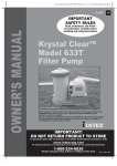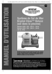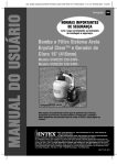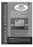
1
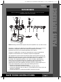
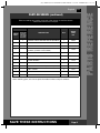
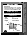
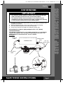
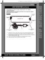
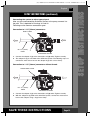
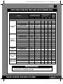
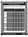
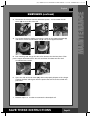
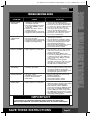
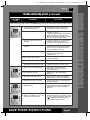
(131) MODEL CS8110 SALTWATER SYSTEM ENGLISH 7.5” X 10.3” PANTONE 295U 07/28/2010
OWNER’S MANUAL
English
131
IMPORTANT
SAFETY RULES
Read, understand, and follow all
instructions carefully before
installing and using this product.
Krystal Clear
®
Saltwater System
Model CS8110
For illustrative purposes only.
Don’t forget to try these other fine Intex products: pools, pool accessories,
inflatable pools and in-home toys, airbeds and boats available at fine
retailers or visit our website.
IMPORTANT!
DO NOT RETURN PRODUCT TO STORE
To purchase parts and accessories or to obtain non-technical assistance,
Visit www.intexcorp.com
For technical assistance and missing parts call us toll-free (for U.S. and Canadian Residents):
1-800-234-6839
Monday through Friday, 8:30am to 5:00pm Pacific Time
131**-R0-1108
(131) MODEL CS8110 SALTWATER SYSTEM ENGLISH 7.5” X 10.3” PANTONE 295U 07/28/2010
131
Warnings............................................................................... 3
Parts List & References....................................................... 4-6
Product Information & Specifications................................ 7
Setup Instructions................................................................ 8-12
Salt & Pool Water Volumes................................................... 13
Intex Pools Salt Table........................................................... 14
Intex Pools Operating Time Table........................................ 15
Intex Pools Cyanuric Acid Table.......................................... 16
Non-Intex Pools Salt Table................................................... 17
Non-Intex Pools Operating Time Table................................ 17
Non-Intex Pools Cyanuric Acid Table................................. 17
Operating Instructions......................................................... 18-19
LED Code Chart.................................................................... 20
Maintenance.......................................................................... 21-23
Long Term Storage............................................................... 23
Pool Maintenance and Chemical Definitions..................... 24
Troubleshooting Guide........................................................ 25-26
General Aquatic Safety........................................................ 27
Limited Warranty................................................................... 28
Intex Service Center Locations........................................... 29
SAVE THESE INSTRUCTIONS
Page 2
TABLE OF CONTENTS
English
(131) MODEL CS8110 SALTWATER SYSTEM ENGLISH 7.5” X 10.3” PANTONE 295U 07/28/2010
131
IMPORTANT SAFETY RULES
Read, Understand and Follow All Instructions Carefully Before Installing and Using this Product.
READ AND FOLLOW ALL INSTRUCTIONS
WARNING
• To reduce the risk of injury, do not permit children to use this product. Always
supervise children and those with disabilities.
• Children must stay away from this product and all electrical cords.
• Assembly and disassembly by adults only.
• Risk of electric shock. Connect this product only to a grounding type receptacle
protected by a ground-fault circuit interrupter (GFCI). Contact a qualified electrician
if you cannot verify that the receptacle is protected by a GFCI.
• Always unplug this product from the electrical outlet before removing, cleaning,
servicing or making any adjustment to the product.
• Do not bury the electrical cord. Locate the cord where it will not be damaged by
lawn mowers, hedge trimmers and other equipment.
• To reduce the risk of electric shock, the supply cord cannot be replaced. If the cord
is damaged, the appliance should be replaced immediately.
• To reduce the risk of electric shock, do not use extension cords, timers, plug
adaptors or converter plugs to connect unit to electric supply; provide a properly
located outlet.
• Do not attempt to plug in or unplug this product while standing in water or when
your hands are wet.
• Do not use an appliance leakage current interrupter (ALCI) in place of a GFCI
since the ALCI will not protect people.
• Position this product away from the pool, so as to prevent children from climbing on
it and accessing the pool.
• Do not operate this product when the pool is occupied.
• This product is intended to be used only for the purposes described in the manual!
FAILURE TO FOLLOW THESE WARNINGS MAY RESULT IN
PROPERTY DAMAGE, ELECTRIC SHOCK, ENTANGLEMENT OR
OTHER SERIOUS INJURY OR DEATH.
CAUTION
This product is for use with storable pools only. Do not use with
permanently-installed pools. A storable pool is constructed so that it is capable of
being readily disassembled for storage and reassembled to its original integrity. A
permanently-installed pool is constructed in or on the ground or in a building such
that it cannot be readily disassembled for storage.
These product warnings, instructions and safety rules provided with the product represent
some common risks of water recreation devices and do not cover all instances of risk and
danger. Please use common sense and good judgement when enjoying any water activity.
For portable Above-Ground-Pools only
SAVE THESE INSTRUCTIONS
Page 3
SAFETY RULES
English
(131) MODEL CS8110 SALTWATER SYSTEM ENGLISH 7.5” X 10.3” PANTONE 295U 07/28/2010
131
PARTS LIST
English
PARTS LIST
1
2
3
4
5
6
7
8
9
* Optional
* Optional
10
11
12
NOTE: Drawings for illustration purpose only. Actual product may vary. Not to scale.
SAVE THESE INSTRUCTIONS
Page 4
(131) MODEL CS8110 SALTWATER SYSTEM ENGLISH 7.5” X 10.3” PANTONE 295U 07/28/2010
131
PARTS REFERENCE
Before assembling your product, please take a few minutes to check the contents
and become familiar with all the parts.
3
5
7
1
2
4
2
6
2
9
8
10
NOTE: Drawings for illustration purpose only. Actual product may vary. Not to scale.
Operation is subject to the following two conditions: (1) this device may not cause
interference, and (2) this device must accept any interference, including
interference that may cause undesired operation of the device.
Changes or modifications not expressly approved by the party responsible for
compliance could void the user’s authority to operate the equipment.
This equipment has been tested and found to comply with the limits for Class B
digital device, pursuant to part 15 of the FCC Rules. These limits are designed to
provide reasonable protection against harmful interference in a residential
installation. This equipment generates, uses and can radiate radio frequency
energy and, if not installed and used in accordance with the instructions, may
cause harmful interference to radio or television reception, which can be
determined by turning the equipment off and on, the user is encouraged to try to
correct the interference by one or more of the following measures:
• Reorient or relocate the receiving antenna.
• Increase the separation between the equipment and the receiver.
• Connect the equipment into an outlet on a circuit different from that to which the
receiver is connected.
• Consult the dealer or an experienced radio/TV technician for help.
SAVE THESE INSTRUCTIONS
Page 5
PARTS REFERENCE
English
(131) MODEL CS8110 SALTWATER SYSTEM ENGLISH 7.5” X 10.3” PANTONE 295U 07/28/2010
131
PARTS REFERENCE (continued)
Before assembling your product, please take a few minutes to check the contents
and become familiar with all the parts.
REF. NO.
DESCRIPTION
QTY.
SPARE
PART
NO.
ADAPTOR A WITH THREADED COLLAR (OPTIONAL)
1
10849
2
O-RING A
3
10712
3
SCREW
4
10713
4
ELECTROLYTIC CELL (WITH TITANIUM
PLATES) (O-RING A INCLUDED)
1
11233
5
COPPER ELECTRODE
1
11234
6
FLOW SENSOR CONDUIT
1
11250
7
FLOW SENSOR
1
11143
8
CONNECTOR HOSE WITH THREADED FITTINGS
1
10720
THREADED ADAPTOR B (OPTIONAL)
1
10722
10
CELL COVER
2
11131
11
CHLORINE TEST STRIPS
1
19635
12
COPPER TEST STRIPS
1
11254
COMMON
PARTS
PARTS FOR
CONNECTION
TO FILTER
PUMPS WITH
1-1/4" (32MM)
HOSE SIZE
1
9
When ordering parts, be sure to quote the model number and part numbers.
SAVE THESE INSTRUCTIONS
Page 6
PARTS REFERENCE
English
(131) MODEL CS8110 SALTWATER SYSTEM ENGLISH 7.5” X 10.3” PANTONE 295U 07/28/2010
131
HOW THE CHLORINE IS GENERATED
This product is specially designed for above ground pools. It will destroy the
bacteria, oxidize bather organics and control algae, which provide a safe, clean and
comfortable swimming pool.
Common salt (sodium chloride) is made up of two elements, sodium and chloride.
During the installation of your Saltwater System, a measured quantity of salt is
dissolved in the pool water to make it slightly salty. The pool water flows through
the Saltwater System ’s electrolytic cell to produce chlorine. The chlorine dissolves
in the water and instantly starts destroying bacteria and algae. It also oxidizes all
other organic materials.
HOW COPPER IONS ARE GENERATED
Low voltage direct current is applied to the copper electrode, and copper ions are
generated and dissolved instantly in the water. Copper is an effective algaecide,
which will prevent algae from growing in the pool.
PRODUCT SPECIFICATIONS
Power:
Amperage:
Wattage:
Ideal Salt Level:
Maximum Chlorine Output/hour:
Copper Ionizer Output Current:
Minimum Flow Rate:
Limited Warranty:
Copper electrodes
110 - 120 Volt AC
1.1A
125W
3000 ppm (parts per million)
12 grams/hour
175 mA
700 ~ 4000 gallons/hour (2650 - 15140 liters/hour)
2 Years (see “Limited Warranty”)
Electrolytic Cell
Flow Sensor
Hose Returning
Water to Pool
Hose from
Filter Pump
Power Switch
Power Supply
Electronic
Control Station
SAVE THESE INSTRUCTIONS
Page 7
PRODUCT I NFORM ATI ON/ SPECS
English
(131) MODEL CS8110 SALTWATER SYSTEM ENGLISH 7.5” X 10.3” PANTONE 295U 07/28/2010
131
SETUP INSTRUCTIONS
IMPORTANT
• The Saltwater System requires a separate filter pump [700~4000 gph
(2650~15140 lph)] to drive the water and function properly.
• The Saltwater System must be installed as the last piece of pool
equipment in the water return line to the pool as displayed in Drawing
#1. This location extends the life of the titanium plates.
1. Assemble the above-ground-pool (AGP) and its filter pump according to their
installation instructions.
2. Take the Saltwater System and its accessories out of the packaging.
3. Place the Saltwater System in line after the filter pump.
4. Connect the connector hose (8) to the Saltwater System inlet.
Connecting the system to pump and pool with 1-1/4” (32mm)
connections/hoses:
The saltwater system features 1-1/2” (38mm) connections. It is accordingly
supplied with adaptors A (1) and B (9) for connecting to the small 1-1/4”
(32mm) diameter connections/hoses. Install as follows:
Drawing #1
WATER TO
POOL
WATER FROM
POOL
SWIMMING POOL
ID 1-1/4”
(32mm) HOSE
FILTER
PUMP
BOOST
ID 1-1/4” (32mm)
HOSE
SALTWATER
SYSTEM
9
1
8
9
SAVE THESE INSTRUCTIONS
Page 8
SETUP INSTRUCTI ONS
English
(131) MODEL CS8110 SALTWATER SYSTEM ENGLISH 7.5” X 10.3” PANTONE 295U 07/28/2010
131
SETUP INSTRUCTIONS (continued)
1. Go directly to step 2 if your pool is empty. If your above-ground-pool is filled
with water, unscrew the strainer grids from the strainer connectors and insert
the black hat-like plugs into the connectors, before installing the saltwater pool
system.
2. Connect the adaptor A (1) to the electrolytic cell (4) outlet as shown in Drawing
#1. Tighten securely.
4
1
3. Disconnect the water return hose from the filter pump connection and connect
it to the adaptor A (1) on the Saltwater System with a hose clamp. (see
Drawing #1)
4. Connect adaptor B (9) to the connector hose (8). Tighten securely. (see
Drawing #1)
9
8
5. Connect adaptor B (9) to filter pump outlet (lower connection). Tighten
securely.
9
8
Filter
Pump
6. Remove the black hat-like plugs that prevent water from flowing out of the pool.
Now, return the strainer grids to the strainer connectors.
SAVE THESE INSTRUCTIONS
Page 9
SETUP INSTRUCTI ONS
English
(131) MODEL CS8110 SALTWATER SYSTEM ENGLISH 7.5” X 10.3” PANTONE 295U 07/28/2010
131
SETUP INSTRUCTIONS (continued)
Connecting the system to pump and pool with 1-1/2” (38mm)
connections/hoses:
Pump and pool with 1-1/2” (38mm) connections do not require the adaptors
A (1) or B (9). Install as follows:
Drawing #2
PLUNGER
VALVE
WATER TO
POOL
SWIMMING POOL
WATER FROM
POOL
FILTER
PUMP
BOOST
ID 1-1/2” (38mm)
HOSE
SALTWATER
SYSTEM
8
ID 1-1/2” (38mm)
HOSE
1. Go directly to step 2 if your pool is empty. If your above-ground-pool is filled
with water, close the plunger valves before installing the Saltwater System.
2. Disconnect the water return hose from the filter pump connection and connect
it to the Saltwater System outlet.
3. Connect the connector hose (8) to the filter pump outlet connection.
4. Open the plunger valves to allow the water to flow.
SAVE THESE INSTRUCTIONS
Page 10
SETUP INSTRUCTI ONS
English
(131) MODEL CS8110 SALTWATER SYSTEM ENGLISH 7.5” X 10.3” PANTONE 295U 07/28/2010
131
SETUP INSTRUCTIONS (continued)
Connecting the system to other types of pump (with different type of
thread or no thread):
The Saltwater System can also be adapted to other filter pumps with different
thread or those without a thread on the connection.
Connection to 1-1/4” (32mm) hose:
9
8
FILTER PUMP
BOOST
ID 1-1/4” (32mm)
CONNECTION
SALTWATER SYSTEM
1. Connect one end of adaptor B (9) to the connector hose (8). Tighten securely.
2. Now, connect the other end of adaptor B (9) to the filter pump outlet. Tighten
securely.
Connection to 1-1/2” (38mm) hose with clamp:
8
LARGE HOSE
CLAMP
FILTER PUMP
BOOST
ID 1-1/2” (38mm)
CONNECTION
SALTWATER SYSTEM
1. Connect the connector hose (8) to the filter pump outlet connection with a large
hose clamp. Tighten securely.
SAVE THESE INSTRUCTIONS
Page 11
SETUP INSTRUCTI ONS
English
(131) MODEL CS8110 SALTWATER SYSTEM ENGLISH 7.5” X 10.3” PANTONE 295U 07/28/2010
131
SETUP INSTRUCTIONS (continued)
Connecting the system to other types of pool
After you have connected the Saltwater System to the pump, connect it to
the pool. This is depicted in Drawings #1 and #2.
Following are the common connection types:
Connection to 1-1/4” (32mm) connectors:
HOSE CLAMP
BOOST
ID 1-1/4” (32mm)
HOSE
1
SALTWATER SYSTEM
1. Connect the adaptor A (1) to the electrolytic cell (4) outlet. Tighten securely.
2. The adapter A (1) is now fitted to the Saltwater System. The following step is to
connect the water return hose to the adaptor A (1) with a hose clamp.
Connection to 1-1/2” (38mm) connectors without thread:
LARGE HOSE CLAMP
BOOST
ID 1-1/2” (38mm)
HOSE
1
SALTWATER SYSTEM
1. Connect the adaptor A (1) to the electrolytic cell (4) outlet. Tighten securely.
2. With the adaptor A (1) fixed to the Saltwater System, connect the water return
hose to the adaptor, using a large hose clamp.
SAVE THESE INSTRUCTIONS
Page 12
SETUP INSTRUCTI ONS
English
(131) MODEL CS8110 SALTWATER SYSTEM ENGLISH 7.5” X 10.3” PANTONE 295U 07/28/2010
131
SALT & POOL WATER VOLUMES
• Which kind of salt to use:
Use only Sodium Chloride Salts
Use only sodium chloride (NaCl) salt that is at least 99.8% pure. It is also
acceptable to use water conditioning salt pellets (the compressed forms of
evaporated salt). However, it will take a longer time for them to dissolve.
Do not use iodized or yellow (yellow prussiate of soda) colored salt.
Salt is added to the pool water and the electrolytic cell uses the salt to create
chlorine. The purer the salt the better the performance of the electrolytic cell.
• Optimum Salt Levels
The ideal salt level in the pool water is between 2500-3500 ppm (parts per million).
The optimal level is 3000 ppm.
A too low salt level will reduce the efficiency of the Saltwater System and result in
low chlorine production. A high salt level may generate a salty taste to the pool
water (this may occur at a salt level above 3500-4000ppm). Too high a salt level
may damage the power supply and cause corrosion to the pool metal fixtures and
accessories. The Salt Table page of this manual, shows the correct dosage of salt
needed. The salt in the pool is constantly recycled. The loss of salt is due only to
pool water being physically removed from the pool. Salt is not lost due to
evaporation.
• Adding Salt
1.
2.
3.
4.
Switch the filter pump on to start the water circulation.
Keep the Saltwater System turned off.
Determine the amount of salt to be added (see “Salt Table”).
Evenly spread the proper amount of salt around the inside perimeter of the
pool.
5. Avoid clogging the filter. Do not add salt through the skimmer.
6. Brush the pool bottom to speed up the dissolving process. Do not allow salt to
pile up on the bottom of the pool. Run the filter pump 24 consecutive hours to
thoroughly dissolve the salt.
7. After 24 hours and if all the salt is dissolved, turn on the Saltwater System and
set the saltwater pool system to desired operating time (see “Operating Time
Table”).
• Removing Salt
If too much salt has been added, the unit will beep and display “Code 92” (see
“Alarm Codes”). You will need to lower the salt concentration. The only way to do so,
is to partially drain the pool and refill it with fresh water. Drain and refill
approximately 20% of the pool’s water until the “Code 92” disappears.
• Pool Volume Calculation
Types of Pool
Gallons
(pool size in feet)
Cubic Meters
(pool size in meters)
Rectangular
Length x Width x Average Depth x 7.5
Length x Width x Average Depth
Circular
Length x Width x Average Depth x 5.9
Length x Width x Average Depth x 0.79
Oval
Length x Width x Average Depth x 6.0
Length x Width x Average Depth x 0.80
SAVE THESE INSTRUCTIONS
Page 13
SALT & POOL WATER VOLUMES
English
(131) MODEL CS8110 SALTWATER SYSTEM ENGLISH 7.5” X 10.3” PANTONE 295U 07/28/2010
English
131
INTEX POOLS SALT TABLE
This table shows the amount of salt needed to achieve and maintain the optimal 3000 ppm
salt level.
Pool Size
Water Capacity (Calculated at Salt Needed for
90% for Frame Pool and 80%
Startup
for Easy Set & Oval Pool)
3.0g/L (3000ppm)
Salt Needed when
Low Salt Detected
(CODE “91”)
(Gals)
(Liters)
(Lbs)
(Kgs)
(Lbs)
(Kgs)
15' x 33" (457cm x 84cm)
2587
9792
65
30
20
10
INTEX ABOVE GROUND POOLS (AGP’s)
EASY SET®
POOL
CIRCULAR
METAL
FRAME POOL
15' x 36" (457cm x 91cm)
2822
10681
65
30
20
10
15' x 42" (457cm x 107cm)
3284
12430
80
35
20
10
15' x 48" (457cm x 122cm)
3736
14141
95
45
20
10
16' x 42" (488cm x 107cm)
3754
14209
95
45
20
10
16' x 48" (488cm x 122cm)
4273
16173
110
50
30
15
18' x 42" (549cm x 107cm)
4786
18115
120
55
30
15
18' x 48" (549cm x 122cm)
5455
20647
135
60
35
15
18' x 52" (549cm x 132cm)
5894
22309
150
65
40
20
15' x 36" (457cm x 91cm)
3282
12422
80
35
20
10
15' x 42" (457cm x 107cm)
3861
14614
100
45
20
10
15' x 48" (457cm x 122cm)
4440
16805
110
50
30
15
16' x 48" (488cm x 122cm)
5061
19156
125
55
30
15
18' x 48" (549cm x 122cm)
6423
24311
160
75
40
20
18' x 52" (549cm x 132cm)
6981
26423
175
80
45
20
20' x 52" (610cm x 132cm)
8638
32695
220
100
60
25
43462
290
130
75
35
24' x 48" (732cm x 122cm)
11483
24' x 52" (732cm x 132cm)
12481
47241
310
140
85
40
16' x 48" (488cm x 122cm)
5061
19156
125
55
35
15
POOL
18' x 52" (549cm x 132cm)
6981
26423
175
80
45
20
SEQUOIA SPIRIT®
POOL SET
16'8" x 49" (508cm x 124cm)
5061
19156
125
55
35
15
18'8" x 53" (569cm x 135cm)
6981
26423
175
80
45
20
18' x 10' x 42" (549cm x 305cm x 107cm)
2885
10920
65
30
20
10
OVAL FRAME 20' x 12' x 48" (610cm x 366cm x 122cm)
POOL
24' x 12' x 48" (732cm x 366cm x 122cm)
4393
16628
110
50
30
15
5407
20465
135
60
35
15
28' x 12' x 48" (853cm x 366cm x 122cm)
6420
24300
160
75
40
20
18' x 9' x 52" (549cm x 274cm x 132cm)
RECT. ULTRA 24' x 12' x 52" (732cm x 366cm x 132cm)
FRAME POOL
32' x 16' x 52" (975cm x 488cm x 132cm)
4545
17203
115
50
30
15
8403
31805
210
100
55
25
14364
54368
360
165
95
45
ULTRA FRAME®
SAVE THESE INSTRUCTIONS
Page 14
(131) MODEL CS8110 SALTWATER SYSTEM ENGLISH 7.5” X 10.3” PANTONE 295U 07/28/2010
English
131
INTEX POOLS OPERATING TIME TABLE (WITH CYANURIC ACID)
Water Capacity (Calculated at Operating Time (hours) Intex Filter
90% for Frame Pool and 80% at different ambient/air
pump
temperatures
for Easy Set & Oval Pool)
Operating
Time
10 - 19°C 20 - 28°C 29 - 36°C
(Gals)
(Liters)
(50 - 66°F) (68 - 82°F) (84 - 97°F) (hours)
Pool Size
INTEX ABOVE GROUND POOLS (AGP’s)
EASY SET®
POOL
CIRCULAR
METAL
FRAME POOL
15' x 33" (457cm x 84cm)
2587
9792
1
1
1
2
15' x 36" (457cm x 91cm)
2822
10681
1
1
1
2
15' x 42" (457cm x 107cm)
3284
12430
1
1
2
4
15' x 48" (457cm x 122cm)
3736
14141
1
2
2
4
16' x 42" (488cm x 107cm)
3754
14209
1
2
2
4
16' x 48" (488cm x 122cm)
4273
16173
2
2
2
4
18' x 42" (549cm x 107cm)
4786
18115
2
2
2
4
18' x 48" (549cm x 122cm)
5455
20647
2
2
3
4
18' x 52" (549cm x 132cm)
5894
22309
2
2
3
4
15' x 36" (457cm x 91cm)
3282
12422
1
1
2
4
15' x 42" (457cm x 107cm)
3861
14614
1
2
2
4
15' x 48" (457cm x 122cm)
4440
16805
2
2
2
4
16' x 48" (488cm x 122cm)
5061
19156
2
2
2
4
18' x 48" (549cm x 122cm)
6423
24311
2
2
3
4
18' x 52" (549cm x 132cm)
6981
26423
2
2
3
4
20' x 52" (610cm x 132cm)
8638
32695
3
3
4
4
24' x 48" (732cm x 122cm)
11483
43462
4
4
5
6
24' x 52" (732cm x 132cm)
12481
47241
5
5
6
8
2
4
ULTRA FRAME®
16' x 48" (488cm x 122cm)
5061
19156
2
2
POOL
18' x 52" (549cm x 132cm)
6981
26423
2
2
3
4
SEQUOIA SPIRIT®
POOL SET
16'8" x 49" (508cm x 124cm)
5061
19156
2
2
2
4
18'8" x 53" (569cm x 135cm)
6981
26423
2
2
3
4
18' x 10' x 42" (549cm x 305cm x 107cm)
2885
10920
1
1
1
2
OVAL FRAME 20' x 12' x 48" (610cm x 366cm x 122cm)
POOL
24' x 12' x 48" (732cm x 366cm x 122cm)
4393
16628
2
2
2
4
5407
20465
2
2
3
4
28' x 12' x 48" (853cm x 366cm x 122cm)
6420
24300
2
2
3
4
18' x 9' x 52" (549cm x 274cm x 132cm)
4545
17203
2
2
2
4
8403
31805
3
3
4
6
14364
54368
6
6
7
8
RECT. ULTRA
24' x 12' x 52" (732cm x 366cm x 132cm)
FRAME POOL
32' x 16' x 52" (975cm x 488cm x 132cm)
IMPORTANT
The filter pump running time should be 1 hour longer than the required
operating time of the Saltwater System.
SAVE THESE INSTRUCTIONS
Page 15
(131) MODEL CS8110 SALTWATER SYSTEM ENGLISH 7.5” X 10.3” PANTONE 295U 07/28/2010
English
131
INTEX POOLS CYANURIC ACID TABLE
Cyanuric acid is a chemical that reduces the loss of chlorine in water due to ultraviolet rays. To
maintain maximum performance, we recommend that the cyanuric acid level be maintained at
approximately 1% of the salt, i.e. 100 Lbs (45 Kgs) salt x1% = 1 Lbs (0.45 Kgs) cyanuric acid.
Pool Size
INTEX ABOVE GROUND POOLS (AGP’s)
15' x 33" (457cm x 84cm)
EASY SET®
POOL
CIRCULAR
METAL
FRAME POOL
ULTRA FRAME®
POOL
SEQUOIA SPIRIT®
POOL SET
OVAL FRAME
POOL
RECT. ULTRA
FRAME POOL
Water Capacity (Calculated at
90% for Frame Pool and 80%
for Easy Set & Oval Pool)
Cyanuric Acid Needed for
Startup
0.03g/L (30ppm)
(Gals)
(Liters)
(Lbs)
(Kgs)
2587
9792
0.6
0.3
15' x 36" (457cm x 91cm)
2822
10681
0.7
0.3
15' x 42" (457cm x 107cm)
3284
12430
0.8
0.4
15' x 48" (457cm x 122cm)
3736
14141
0.9
0.4
16' x 42" (488cm x 107cm)
3754
14209
0.9
0.4
16' x 48" (488cm x 122cm)
4273
16173
1.1
0.5
18' x 42" (549cm x 107cm)
4786
18115
1.2
0.5
18' x 48" (549cm x 122cm)
5455
20647
1.4
0.6
18' x 52" (549cm x 132cm)
5894
22309
1.5
0.7
15' x 36" (457cm x 91cm)
3282
12422
0.8
0.4
15' x 42" (457cm x 107cm)
3861
14614
1.0
0.4
15' x 48" (457cm x 122cm)
4440
16805
1.1
0.5
16' x 48" (488cm x 122cm)
5061
19156
1.3
0.6
18' x 48" (549cm x 122cm)
6423
24311
1.6
0.7
18' x 52" (549cm x 132cm)
6981
26423
1.7
0.8
20' x 52" (610cm x 132cm)
8638
32695
2.2
1.0
24' x 48" (732cm x 122cm)
11483
43462
2.9
1.3
24' x 52" (732cm x 132cm)
12481
47241
3.1
1.4
16' x 48" (488cm x 122cm)
5061
19156
1.3
0.6
18' x 52" (549cm x 132cm)
6981
26423
1.7
0.8
16'8" x 49" (508cm x 124cm)
5061
19156
1.3
0.6
18'8" x 53" (569cm x 135cm)
6981
26423
1.7
0.8
18' x 10' x 42" (549cm x 305cm x 107cm)
2885
10920
0.7
0.3
20' x 12' x 48" (610cm x 366cm x 122cm)
4393
16628
1.1
0.5
24' x 12' x 48" (732cm x 366cm x 122cm)
5407
20465
1.4
0.6
28' x 12' x 48" (853cm x 366cm x 122cm)
6420
24300
1.6
0.7
18' x 9' x 52" (549cm x 274cm x 132cm)
4545
17203
1.1
0.5
24' x 12' x 52" (732cm x 366cm x 132cm)
8403
31805
2.1
1.0
32' x 16' x 52" (975cm x 488cm x 132cm)
14364
54368
3.6
1.6
SAVE THESE INSTRUCTIONS
Page 16
(131) MODEL CS8110 SALTWATER SYSTEM ENGLISH 7.5” X 10.3” PANTONE 295U 07/28/2010
English
131
SALT CALCULATION FORMULA FOR ALL POOLS
Salt Needed for Startup
(Lbs)
Salt Needed for Startup
(Kgs)
Water Capacity (Gals) x 0.025 Water Capacity (Liters) x 0.003
Salt Needed when
Salt Needed when
Low Salt Detected (Lbs) Low Salt Detected (Kgs)
Water Capacity (Gals) x 0.0067
Water Capacity (Liters) x 0.0008
SALT TABLE FOR COMMON NON-INTEX POOLS
Water Capacity
Salt Needed when
Low Salt Detected
(CODE “91”)
Salt Needed for Startup
(Gals)
(Liters)
2000
4000
6000
8000
10000
12000
14000
7500
15000
22500
30000
37500
45500
53000
(Lbs)
(Kgs)
(Lbs)
(Kgs)
50
100
150
200
250
300
350
20
45
65
90
110
135
160
10
25
40
55
70
80
95
5
10
20
25
30
35
45
OPERATING TIME TABLE FOR COMMON NON-INTEX POOLS
Operating Time (hours)
at different ambient/air temperatures
10 - 19°C
20 - 28 °C
29 - 36 °C
(50 - 66°F)
(68 - 82 °F)
(84 - 97 °F)
1
1
1
2
2
2
2
2
3
3
3
4
4
4
5
5
5
6
6
6
7
Water Capacity
(Gals)
(Liters)
2000
4000
6000
8000
10000
12000
14000
7500
15000
22500
30000
37500
45500
53000
CYANURIC ACID TABLE FOR COMMON NON-INTEX POOLS
Cyanuric Acid Needed for Startup
0.03g/L (30ppm)
Water Capacity
(Gals)
(Liters)
(Lbs)
(Kgs)
2000
4000
6000
8000
10000
12000
14000
7500
15000
22500
30000
37500
45500
53000
0.5
1.0
1.5
2.0
2.5
3.0
3.5
0.23
0.45
0.68
0.90
1.13
1.37
1.59
SAVE THESE INSTRUCTIONS
Page 17
(131) MODEL CS8110 SALTWATER SYSTEM ENGLISH 7.5” X 10.3” PANTONE 295U 07/28/2010
131
OPERATION INSTRUCTIONS
1. Turn on the filter pump.
2. Start up the unit:
Plug the power cord into the electrical
outlet and test the GFCI/RCD (circuit breaker).
Switch on the unit. Code “00” appears on
the electronic control station’s LED, indicating
that the unit is in a Stand-By Mode. This is normal.
3. Unlock keypad controls:
Press and hold the -- button for 2 seconds until you hear a
short “beep”. Then press and hold the
button for another 2
seconds until you hear the second short “beep”. The LED
flashes “00”. This procedure unlocks the keypad control
buttons.
4. Set operating hours for Saltwater system:
Increase the scheduled number of operating
hours by pressing the button
. Or reduce
them by pressing the button
. See the
“Operating Time Table” for the required
operating hours related to each pool size.
Press the button
to select the desired
hours. You can press
if you have
selected too many hours. The built-in timer
will now activate your Saltwater System, at
the same time each day, for the number of
(1 to 12 hours max per cycle)
hours you have set.
NOTE: The Saltwater System will not operate if the filter pump is not operating.
Make sure to program your filter pump (or start it manually) for operation
beginning 5 minutes before the saltwater system and finishing 15 minutes after
the saltwater system.
5. Lock keypad controls:
With the desired hour value showing, press and hold the
button for 2 seconds until you hear a long “beep”. Then press
and hold
for another 2 seconds until you hear the second
long beep. A green “WORKING” indicator on the control panel
will light up within a few seconds to indicate that the saltwater
system has started chlorine production. Locking the control
buttons into this setting prevents unauthorized changing of the
operating cycle.
NOTE: If you forget to lock the keypad controls, the system will
automatically lock it and start working 1 minute later.
6. Readjust operating time if necessary:
The operating hours can be re-adjusted if necessary. Just repeat the steps 3
through 5.
7. Test the copper concentration in the
pool water.
The Saltwater System recommends a
copper level of 0.1 to 0.2 ppm. This is
easily tested by the copper ion test strips
provided. If the test result is 0.1~0.2ppm,
go directly to step 9.
Copper (ppm)
0
SAVE THESE INSTRUCTIONS
0.1
0.2
0.5
0.9
1.3
OK
Page 18
OPERATING INSTRUCTI ONS
English
(131) MODEL CS8110 SALTWATER SYSTEM ENGLISH 7.5” X 10.3” PANTONE 295U 07/28/2010
131
OPERATION INSTRUCTIONS (continued)
8. Boost cycle
• If the test result is below 0.1ppm, press and hold “BOOST”
button for 5 seconds until the indicator lights up and the
LED display “80”. This indicates that the saltwater
system has started copper ion production.
You can press and hold the “BOOST” button for another 5
seconds until the indicator is off, which will cancel the Boost
cycle.
Note: Once the system has started copper ion production, the
boost button can’t be re-set until the power switch is off.
•
The boost operating hours is 4 times the amount of time programmed into the
system, i.e. if your saltwater system operating time is 2 hours, the boost procedure
will run 4 x 2 = 8 hours. After boost procedure has been completed, the system
will automatically switch to the normal working mode.
•
Once the boost is operating, check whether the filter pump operating hours
have been set properly. For example, the boost operating time is 8 hours, the
filter pump should be set to run for 8 hours at least. Increase the filter pump
operating time if necessary.
Note: If an Intex filter pump is attached to the system, set the pump switch to
on “I” position.
•
After a heavy rain or if the pool is dirty, press the “BOOST” button to shock the
pool again.
9. Test pool water regularly:
Once the copper level appears to be balanced, test the pool water every week
to maintain the proper sanitizer level.
It’s very important that the free chlorine is between 0.4-1.5 ppm and copper
ion concentration is between 0.1~0.2 ppm. When the copper level is below 0.1
ppm, repeat step 8.
NOTE: A High copper ion concentration may cause blonde hair to exhibit a
green hair. To prevent this, wear a swimming cap during swimming, and wash
hair with special shampoo after using the pool.
See “Troubleshooting Guide”.
10. Stand-by/power saving mode:
• When the cycle ends, the green “SLEEP” indicator on the
control panel lights up and the LED display flashes “93”.
The system is now in Stand-By mode. After a while, it
shuts down and sets itself in a Power Saving mode. The
system will automatically turn itself back on in 24 hours,
starting its daily cycle of chlorine production.
•
The “SLEEP” indicator stays on, while the system is in the
Power Saving mode. The LED display however, goes blank
after 1 hour. Press any button (
or
) to view the last LED
code.
SAVE THESE INSTRUCTIONS
Page 19
OPERATING INSTRUCTI ONS
English
(131) MODEL CS8110 SALTWATER SYSTEM ENGLISH 7.5” X 10.3” PANTONE 295U 07/28/2010
131
LED CODE CHART
LED Reading
Definitions
80
Boost Mode
00
Stand-By Mode (Start-up)
01
Minimum Operating Hour (1 hour remaining)
02
Operating Hours (2 hours remaining)
03
Operating Hours (3 hours remaining)
04
Operating Hours (4 hours remaining)
05
Operating Hours (5 hours remaining)
06
Operating Hours (6 hours remaining)
07
Operating Hours (7 hours remaining)
08
Operating Hours (8 hours remaining)
09
Operating Hours (9 hours remaining)
10
Operating Hours (10 hours remaining)
11
Operating Hours (11 hours remaining)
12
Maximum Operating Hours (12 hours remaining)
90
Alarm Code (Low Water Flow / No Flow)
91
Alarm Code (Low Salt Level)
92
Alarm Code (High Salt Level)
93
Stand-By Mode (Operating Process finished)
“BLANK”
No Power or “Power Saving Mode” waiting to start next
Saltwater System cycle.
IMPORTANT
When Code “90” alarm is shown, ensure the timer of the filter pump is set
one (1) hour longer than the Saltwater System.
If the filter pump does not have a built-in timer, the filter pump needs to
be turned on/off manually every day.
SAVE THESE INSTRUCTIONS
Page 20
LED CODE CHART
English
(131) MODEL CS8110 SALTWATER SYSTEM ENGLISH 7.5” X 10.3” PANTONE 295U 07/28/2010
131
MAINTENANCE
IMPORTANT
Unplug the power cord before cleaning your system. Also close the
plunger valves on your pool or insert the black hat-like plugs in the
strainer opening to prevent water spillage. After completing all
maintenance tasks, you must plug the power cord back in and open the
plunger valves or remove the plugs.
Flow Sensor Cleaning
1. In a counter-clockwise motion unscrew the collar of the flow sensor (7) and
remove it from the electrolytic cell conduit (6). See “Part Reference”.
2. If deposits and debris are seen on the surface of the flow sensor, then use a
garden hose to wash it off.
Hinge
Locator Notch
Connection Ridge
3. If flushing with water does not remove the deposits, use a plastic brush to
clean the surface and the hinge if necessary. Do not use a metal brush.
4. After the flow sensor has been inspected and cleaned, align the locator notch
on the flow sensor to the connection ridge in the conduit. Now turn the collar in
a clockwise motion, tightening the sensor back into its position. Do not
overtighten.
Electrolytic Cell Cleaning
The electrolytic cell (6) has a self cleaning function incorporated into the electronic
control's programming. In most cases this self cleaning action will keep the cell
working at optimum efficiency. If the pool water is hard (high mineral content) the
cell may require periodic manual cleaning. To maintain maximum performance, we
recommend that you open and visually inspect the electrolytic cell (6) monthly.
The following steps provide instructions on how to clean your cell.
Inspection and cleaning:
1. Switch off the unit, unplug the power cord from the electrical socket.
2. For filter pumps with 1-1/4” (32mm) hose size - To prevent water from
flowing out of the pool, unscrew the strainer grids from the strainer connectors
and insert the hat-like plugs into the strainer connectors.
For filter pumps with 1-1/2” (38mm) hose size - Grasp a plunger valve
handle. Turn the handle counter-clockwise, push down until it stops and then
turn it clockwise until the plastic protruding notch anchors in the "0/I" position.
Repeat for the second plunger valve. This prevents the water from flowing out
of the pool.
SAVE THESE INSTRUCTIONS
Page 21
MAINTENANCE
English
(131) MODEL CS8110 SALTWATER SYSTEM ENGLISH 7.5” X 10.3” PANTONE 295U 07/28/2010
131
MAINTENANCE (continued)
3. Disconnect the 2 hoses from the Saltwater System, and assemble the cell
cover (10) at each side of the cell.
4. In a counter-clockwise motion, unscrew the collar of the copper electrode (5)
and remove it from the electrolytic cell (4). Lift up the copper electrode.
5. Pour kitchen grade vinegar into the cell to immerse the titanium plates. Then
put the copper electrode back in the cell, soak them for about one hour until
no colored areas remain.
6. Open one side of the cell cover (10), drain and properly dispose of the vinegar.
Connect the hose which goes from the pool to the cell. Flush the cell with the
pool water.
7. Reverse steps 3, 4, 5 and 6 to reconnect the electrolytic cell.
SAVE THESE INSTRUCTIONS
Page 22
MAINTENANCE
English
(131) MODEL CS8110 SALTWATER SYSTEM ENGLISH 7.5” X 10.3” PANTONE 295U 07/28/2010
131
MAINTENANCE (continued)
INTEX® COPPER ION TEST STRIPS (PACKED WITH THE PRODUCT)
The Copper Ion Test Strips can be used to test the copper ion concentration in the
water.
Directions and Use
1. Dip the entire strip into the water for 3 seconds, then remove it
2. Hold the strip level for 15 seconds. Do not shake excess water from the strip.
3. Now compare the copper ion strip pad to the color chart on the packaging
label.
INTEX® 3-WAY TEST STRIPS (PACKED WITH THE PRODUCT)
The 3-Way Test Strips can test the “Free Chlorine”, “pH”, and “Total Alkalinity” levels
at the same time. We recommend that you test the water chemistry weekly, and
maintain the chlorine concentration at 0.4-1.5 ppm.
Directions and Use
1. Dip the entire strip into the water and remove immediately.
2. Hold the strip level for 15 seconds. Do not shake excess water from the strip.
3. Now compare the strip pad to the color chart on the packaging label. If
necessary, adjust the chemical level in the pool water. It is very important, to
use the proper technique when testing the water's chemical level. Read and
follow the written strip instructions carefully.
LONG TERM STORAGE
1. Disconnect the power cord from the electrical outlet.
2. After the pool is completely empty, disconnect the Saltwater System from the
hoses by reversing the installation instructions.
3. Air-dry the unit before you store it. This might be a good time to visually inspect
and clean the electrolytic cell.
4. Store the unit and accessories in a dry place. The temperature should be
controlled, between 32 degrees Fahrenheit (0 degrees Celsius) and 97
degrees Fahrenheit (36 degrees Celsius).
5. The original package can be used for storage.
SAVE THESE INSTRUCTIONS
Page 23
MAINTENANCE
English
(131) MODEL CS8110 SALTWATER SYSTEM ENGLISH 7.5” X 10.3” PANTONE 295U 07/28/2010
131
POOL MAINTENANCE & CHEMICAL DEFINITIONS
Preferred Water Chemistry Reading
Minimum
Ideal
Copper Ions
0
0.1 - 0.2 ppm
Free Chlorine
0
0.4 - 1.5 ppm
0
0 ppm
Combined Chlorine
pH
7.2
7.4 - 7.6
Total Alkalinity
100 ppm
100 - 140 ppm
Calcium Hardness
150 ppm
200 - 400 ppm
Stabilizer (Cyanuric Acid)
10 ppm
30 - 50 ppm
Maximum
0.2 ppm
3.0 ppm
0.2 ppm
7.8
140 ppm
500 - 1000 ppm
100 ppm
Free Chlorine - Is the chlorine residual present in pool water.
Combined Chlorine - Is formed by the reaction of free chlorine with ammonia
wastes.
Result if too high - Sharp chlorinous odor, eye irritation.
pH - A value that indicates how acidic or basic a solution is.
Result if too low -
Corroded metals, eye & skin irritation,
destruction of total alkalinity.
Result if too high - Scale formation, cloudy water, shorter
filter runs, eye & skin irritation, poor
chlorine efficiency.
Total Alkalinity - Indicates the degree of the water's resistance to change
in pH. It determines the speed and ease of pH change,
so always adjust total alkalinity before adjusting the pH
level.
Result if too low - Corroded metals, eye & skin irritation.
Low alkalinity will cause the pH to be
unstable. Any chemical added to the
water will have an affect on pH.
Result if too high - Scale formation, cloudy water,
eye & skin irritation, poor chlorine
efficiency.
Calcium Hardness - Refers to the amount of calcium and magnesium
dissolved in the water.
Result if too high - Scale will form and will cause the
water to become cloudy.
Stabilizer - Stabilizers extend the life of chlorine in swimming pools.
(Cyanuric Acid)
• Do not add pool chemicals directly to the skimmer. This may damage the cell.
• Maintaining a salt and sanitizer level above the recommended range can
contribute to the corrosion of the pool equipment.
• Check the expiry date of the test kit as the test results may be inaccurate if the
kit is used after that date.
• If, due to heavy pool usage, it is required to increase the sanitizer level, then use
a chemical based on Trichloro-s-triazinetrione or sodium dichloro-s-triazinetrione
dihydrate.
SAVE THESE INSTRUCTIONS
Page 24
MAINTENANCE
English
(131) MODEL CS8110 SALTWATER SYSTEM ENGLISH 7.5” X 10.3” PANTONE 295U 07/28/2010
131
TROUBLESHOOTING GUIDE
PROBLEM
CAUSE
SOLUTION
INSUFFICIENT
CHLORINE
• Insufficient operating hours of
the Saltwater System.
• The salt level in the pool water
is less than 2000ppm. This is
insufficient.
• Chlorine loss due to intense
sunlight exposure.
• The bather load has increased.
• Clogged or dirty electrolytic cell.
• Increase the daily Saltwater System
operating time. See “Operating Instructions”.
• Check the salt level with the Test Kit. Adjust
as needed. See “Salt & Pool Water Volumes”.
• Use a pool cover when the pool is not
in use and/or when the unit is operating.
• Increase the daily Saltwater System
operating time. See “Operating Instructions”.
• Remove the cell for inspection, clean it if
necessary. See “Maintenance”.
INSUFFICIENT
COPPER ION
LEVEL
•
•
•
•
•
• Increase operating time per day. See
“Operating Instructions”.
• Use PH decrease chemical to adjust,
contact your local pool chemical store.
• Increase the operating time per day.
See “Operating Instructions”.
• Remove the cell for inspection, clean it
if necessary. See “Maintenance”.
• Contact Intex Service Center.
POOL IS STAINED
• High copper ion concentration.
• Drain about 20% of the pool water and add
fresh water to decrease the copper ion con
centration below 0.2ppm.
• Add aluminum sulfate: 1000 liters water
need around 2g (1000 gals need 0.27 ounce)
or aluminum potassium sulfate: 1000 liters
water need around 3g (1000 gals need 0.4
ounce) to pool.
• Use a lemon based cleaning product
(preferably containing citric acid). Don’t scrub
with aggressive cleaning products because
this might etch the underlying surface.
WHITE FLAKES IN
THE WATER
• Excessive calcium hardness is
present in pool water.
• Drain about 20 to 25% of the pool
water and add fresh water to decrease
the calcium hardness. Inspect the
electrolytic cell for scale buildup. Clean
the electrolytic cell if necessary.
NO LED DISPLAY
•
•
•
•
• Plug the cell cord firmly into the cell
housing receptacle.
• Reset the RCD/GFCI.
• Contact Intex Service Center.
• Contact Intex Service Center.
GREEN HAIR
• High copper ion concentration.
Insufficient operating hours.
The PH is too high.
The bather load has increased.
Clogged or dirty electrolytic cell.
Copper electrode defective.
No power supply.
RCD/GFCI has not reseted.
A power fuse has blown.
LED failure.
• Drain about 20% of the pool water and
add fresh water to decrease the copper
ion concentration below 0.2ppm.
• Add aluminum sulfate: 1000 liters
water need around 2g (1000 gals need
0.27 ounce) or aluminum potassium
sulfate: 1000 liters water need around
3g (1000 gals need 0.4 ounce) to pool.
• Use ‘Ultra-Swim’ shampoo, or shampoo
containing chelating agents.
IMPORTANT
If you continue to experience difficulty, please contact our Consumer
Service Department for assistance. See back cover for contact information.
SAVE THESE INSTRUCTIONS
Page 25
TROUBLESHOOTING GUIDE
English
(131) MODEL CS8110 SALTWATER SYSTEM ENGLISH 7.5” X 10.3” PANTONE 295U 07/28/2010
131
TROUBLESHOOTING GUIDE (continued)
LED PANEL
CODE
PROBLEM
SOLUTION
LED Panel Code Flash & Alarm On (NOTE: Always turn off the power before cleaning and servicing).
1. Filter pump not attached to
system and/or switch on.
2. Circulation line is blocked.
3. Incorrect inlet and outlet hose
direction.
4. Incorrectly installed flow sensor
conduit.
5. Scale on the flow sensor.
6. Flow sensor cord is loose.
7. Flow sensor failure.
8. Inner timer conflict between
filter pump and saltwater system.
1. Dirt or scale on titanium plates.
2. Low salt level / No salt.
3. Electrolytic cell cord is loose.
4. Possible electrolytic cell failure.
• Ensure filter pump is attached and
operating. See "Setup Instruction".
• If your unit has plunger valves, ensure
that they are open.
• Clear your filter cartridge and cell from
debris and dirt. See “Maintenance”.
• Release all trapped air in the circulation
line. See the filter pump manual.
• Check the direction of the inlet and the
outlet hose. Reverse the hoses if
necessary. See “Set Up Instructions”.
• Check that the arrow on the flow sensor
conduit points in the same direction as
the one on the cell. Reverse the flow
sensor conduit if necessary.
• Clean the flow sensor, paying special
attention to the hinge. See
“Maintenance”.
• Plug the flow sensor firmly into the flow
sensor receptacle.
• Contact Intex Service Center.
• Reset both timers on the filter pump and
saltwater system.See “Boost Cycle”.
• Remove the electrolytic cell for
inspection. Clean it if necessary.
See “Maintenance”.
• Add salt. See “Salt & Pool Water
Volumes”.
• Ensure that the cell cord is plugged
firmly into the cell housing receptacle.
• Contact Intex Service Center. Replace
the cell if needed.
1. High salt level.
• Partially drain the pool and refill it with
fresh water. See “Salt & Pool Water
Volumes”.
1. Display and all lights are off - the
system does not power up.
• Household voltage is too high or too low
(+ 20%). Check the voltage is within the
range stated on the device housing.
• Contact Intex Service Center.
SAVE THESE INSTRUCTIONS
Page 26
TROUBLESHOOTING GUI DE
English
(131) MODEL CS8110 SALTWATER SYSTEM ENGLISH 7.5” X 10.3” PANTONE 295U 07/28/2010
131
GENERAL AQUATIC SAFETY
Water recreation is both fun and therapeutic. However, it involves
inherent risks of injury and death. To reduce your risk of injury, read
and follow all product, package and package insert warnings and
instructions. Remember, however, that product warnings, instructions
and safety guidelines cover some common risks of water recreation,
but do not cover all risks and dangers.
For additional safeguards, also familiarize yourself with the following
general guidelines as well as guidelines provided by nationally
recognized Safety Organizations:
• Demand constant supervision. A competent adult should be appointed as
a “lifeguard” or water watcher, especially when children are in and around
the pool.
• Learn to swim.
• Take the time to learn CPR and first aid.
• Instruct anyone who is supervising pool users about potential pool
hazards and about the use of protective devices such as locked doors,
barriers, etc.
• Instruct all pool users, including children what to do in case of an
emergency.
• Always use common sense and good judgement when enjoying any
water activity.
• Supervise, supervise, supervise.
For additional information on safety, please visit
• The Association of Pool and Spa Professionals: The Sensible Way to
Enjoy Your Aboveground/Onground Swimming Pool www.nspi.org
• American Academy of Pediatrics: Pool Safety for Children www.aap.org
• Red Cross www.redcross.org
• Safe Kids www.safekids.org
• Home Safety Council: Safety Guide www.homesafetycouncil.org
• Toy Industry Association: Toy Safety www.toy-tia.org
SAFETY IN YOUR POOL
Safe swimming depends on constant attention to the rules. The "NO DIVING"
sign within this manual can be posted near your pool to help keep everyone
alert to the danger. You may also wish to copy and laminate the sign for
protection from the elements.
SAVE THESE INSTRUCTIONS
Page 27
SAFETY GUI DELI NES
English
(131) MODEL CS8110 SALTWATER SYSTEM ENGLISH 7.5” X 10.3” PANTONE 295U 07/28/2010
English
131
LIMITED WARRANTY
Your Krystal Clear Saltwater System® has been manufactured using the highest
quality materials and workmanship. All Intex products have been inspected and
found free of defects prior to leaving the factory. This Limited Warranty applies only
to the Krystal Clear Saltwater System®.
The provisions of this Limited Warranty apply only to the original purchaser and is
not transferable. This Limited Warranty is valid for a period of two (2) years from the
date of the initial retail purchase. Keep your original sales receipt with this manual,
as proof of purchase will be required and must accompany warranty claims or the
Limited Warranty is invalid.
If a manufacturing defect is found within this two (2) years period, please contact the
appropriate Intex Service Center listed in this manual. The Service Center will
determine the validity of the claim. If the Service Center directs you to return the
product, please carefully package the product and send with shipping and insurance
prepaid to the Service Center. Upon receipt of the returned product, the Intex
Service Center will inspect the item and determine the validity of the claim. If the
provisions of this warranty cover the item, the item will be repaired or replaced at no
charge.
Any and all disputes regarding the provisions of this Limited Warranty shall be
brought before an informal dispute settlement board and unless and until the
provisions of these paragraphs are carried forth, no civil action may be instituted.
The methods and procedures of this settlement board shall be subject to the rules
and regulations set forth by the Federal Trade Commission (F.T.C.). IMPLIED
WARRANTIES ARE LIMITED TO THE TERMS OF THIS WARRANTY AND IN NO
EVENT SHALL INTEX, THEIR AUTHORIZED AGENTS OR EMPLOYEES BE
LIABLE TO THE BUYER OR ANY OTHER PARTY FOR DIRECT OR
CONSEQUENTIAL DAMAGES OR LIABILITIES. Some states, or jurisdictions do not
allow the exclusion or limitation of incidental or consequential damages, so the
above limitation or exclusion may not apply to you.
This Limited Warranty does not apply if the Krystal Clear Saltwater System® is
subject to negligence, abnormal use or operation, accident, improper operation,
improper voltage or current contrary to operating instructions, or to damage by
circumstances beyond Intex’s control, including but not limited to, ordinary wear and
tear and damage caused by exposure to fire, flood, freezing, rain, or other
external environmental forces. This Limited Warranty applies only to those parts and
components sold by Intex. The Limited Warranty does not cover unauthorized
alterations, repairs or disassembly by anyone other than Intex Service Center
personnel.
DO NOT GO BACK TO THE PLACE OF PURCHASE FOR RETURN
OR REPLACEMENT. IF YOU ARE MISSING PARTS OR NEED
ASSISTANCE, PLEASE CALL US TOLL-FREE (FOR U.S. AND
CANADIAN RESIDENTS): 1-800-234-6839.
Proof of Purchase must accompany all returns or the warranty claim will be invalid.
SAVE THESE INSTRUCTIONS
Page 28
(131) MODEL CS8110 SALTWATER SYSTEM ENGLISH 7.5” X 10.3” PANTONE 295U 07/28/2010
English
COUNTRIES/REGIONS
SERVICE CENTER LOCATIONS
• UNITED STATES
• CANADA
INTEX RECREATION CORP.
14779 Bar Harbor Road
Fontana, CA 92336
Tel: 1-800-234-6839
Fax: 310-549-2900
Website: www.intexcorp.com (U.S./Canada only)
Consumer Service Hours: 8:30 am to 5:00 pm
Pacific Time, Mon. thru FRI. only.
• MEXICO
KAY INTERNACIONAL, S.A. DE C.V.
SAN JERONIMO # 550- INT.501 Y 502. COL.
JARDINES DEL PEDREGAL. C.P. 01900
MÉXICO D.F.
Tel: 01-800-347-4020 (Collect Call)
Tel: 55-9172-8035
Fax: 55-9172-8047
E-mail: [email protected]
Website: www.intexmexico.com.mx
•
•
•
•
•
•
SUPRO MUNDIAL S.A./
PRODUCTOS SUPERIORES S.A.
Boulevard Andrews, Albrook,
Panama, Rep. of Panama
Tel: 507-300-3800
Fax: 507-300-3813
E-mail: [email protected]
PANAMA
PARAGUAY
ECUADOR
HONDURAS
EL SALVADOR
NICARAGUA
• COSTA RICA
• DOMINICAN REPUBLIC
• GUATEMALA
• COLOMBIA
• VENEZUELA
CENTURY USA, LLC
4731 W. Atlantic Ave., Suite B-3
Delray Beach, FL 33445, USA
Tel: 561-495-0648
Fax: 561-495-4782
E-mail: [email protected]
• MIDDLE EAST REGION
REGION
FIRST GROUP INTERNATIONAL
AL MOOSA GROUP BUILDING, 1ST FLOOR,
OFFICE 102 & 103, UMM HURAIR ROAD,
KARAMA, DUBAI, UAE
TEL: 00971-4-800INTEX(46839) / +971-4-3373322
FAX: 00971-4-3375115
E-mail: [email protected].
Website: www.firstgroupinternational.com
• ASIA
INTEX DEVELOPMENT CO. LTD.
9th Floor,
Dah Sing Financial Centre
108 Gloucester Road,
Wanchai, Hong Kong
Tel: 852-28270000
Fax: 852-23118200
E-mail: [email protected]
Website: www.intexdevelopment.com
131
For answers to most frequently asked questions, please visit www.intexcorp.com.
Non U.S. Residents, please visit www.intexdevelopment.com.
SAVE THESE INSTRUCTIONS
Page 29
(131) MODEL CS8110 SALTWATER SYSTEM ENGLISH 7.5” X 10.3” PANTONE 295U 07/28/2010
INTEX
®
English
For Residents of the U.S. & Canada:
INTEX RECREATION CORP.
Attn: Consumer Service
14779 Bar Harbor Road
Fontana, CA 92336
Phone: 1-800-234-6839
Fax: (310) 549-2900
Consumer Service Hours:
8:30 am to 5:00 pm Pacific time
Monday thru Friday only
Website: www.intexcorp.com
For Residents outside of the U.S. and Canada:
Please refer to the Service Center Locations
©2010 Intex Marketing Ltd. - Intex Development Co. Ltd. Intex Trading Ltd. - Intex Recreation Corp.
All rights reserved/Tous droits réservés/Todos los
derechos reservados/Alle Rechte vorbehalten.
Printed in China/Imprimé en Chine/Impreso en
China/Gedruckt in China.
®™ Trademarks used in some countries of the world under
license from/®™ Marques utilisées dans certains pays sous
licence de/Marcas registradas utilizadas en algunos países
del mundo bajo licencia de/Warenzeichen verwendet in
einigen Ländern der Welt in Lizenz von/Intex Marketing Ltd.
to/à/a/an Intex Trading Ltd., Intex Development Co. Ltd.,
G.P.O Box 28829, Hong Kong & Intex Recreation Corp.,
P.O. Box 1440, Long Beach, CA 90801 • Distributed in the
European Union by/Distribué dans l’Union Européenne
par/Distribuido en la unión Europea por/Vertrieb in der
Europäischen Union durch/Intex Trading B.V., P.O. Box nr.
1075 – 4700 BB Roosendaal – The Netherlands