1
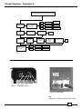
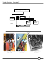
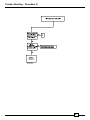
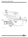
Refrigerator
Service Manual
Models:
DC440, DC451, DC490
DE441, DE451, DE461, DE490
MRFT415, MRFT440, MRFT460
NORCOLD, INC.
P.O BOX 4248
SIDNEY, OH 45365-4248
Part No.619730E (01/01)
Trouble Shooting - Table of Contents
-- Procedure A - Thermostat “ON” Compressor does not run ........................................................... 3
-- Procedure B - Compressor Resistance ....................................................................................... 4
-- Procedure C - Power Supply Output Voltage ............................................................................... 5
-- Procedure D - Compressor Amp Draw ........................................................................................ 6
-- Procedure E - Evaporator Thermister Resistance ....................................................................... 7
-- Procedure F - Insufficient Coolling ............................................................................................... 8
-- Procedure G - Refrigerator to Cold .............................................................................................. 9
-- Procedure H - Auto Shut-OFF Device ........................................................................................ 10
-- Wiring Schematic .......................................................................................................................11
-- Procedure I - Ventilation ....................................................................................................... 12-14
-- Quick Reference Repair Sheet .................................................................................................. 15
WARNING
Perform all tests using a fully charged 12 VDC battery. Using other equipment that
supplies DC voltage may cause permanent refrigerator compressor failure.
2
Trouble Shooting - Procedure A
Thermostat "ON" Compressor does not run
NO
Check Battery
Voltage
Short Circuit
DC 5 V
Power Supply
Failure
Change
Power Supply
DC 2 V
Normal
See Procedure B
Measure terminal
voltage of Temperature
Control between
TP1 & TP2
Is Temperature
Control LED on? YES
Wrong
Correct DC Voltage
Compressor runs
YES
(10.5 - 32 VDC)
Good
Check DC Fuse
Change
Temperature
Control
DC 0 V
OK
NO
Check DC
Polarity
Bad
Good
Wrong
Reverse Polarity
& Check operation
(Red+/Blk-)
Replace fuse if defective
10A (DE/DC)
8A (MRFT)
See Figure 2
OK
NO
Good
Measure
terminal voltage of
Temperature Control
between TP2 & TP3
See Figure 1
Compressor runs YES
DC 0 V
Power Supply
Failure
Change
Power Supply
DC 12 to
32 V
Normal
See Procedure B
ART01190
Red
TP3
Brn
TP1
Blk
TP2
Yel
Org
Figure 1 - Temperature Control
Figure 2 - Power Supply
Note:
If 10 Amp fuse is blown, check wiring of vehicle
3
Trouble Shooting - Procedure B
Compressor Resistance
Note: Perform procedure at room temperature.
0
Measure
compressor
resistance
Internal Compressor
Failure
3
+/-.5
Normal
Change
Cooling Unit
See Procedure C
ART01192
Turn the refrigerator to OFF.
Remove the black wire to the compressor. Measure
the resistance of the compressor bewteen Point A and
Point B.
B
A
Figure 2 - Measuring Compressor Resistance
4
Trouble Shooting - Procedure C
Power Supply Output Voltage
Measure voltage
between A & B
at the compressor
Below
15 V AC
Power Supply
Failure
Change
Power Supply
0 V AC
Power Supply
Failure
Remove Power
Supply
Check F3 fuse
on circuit board
Ohms:
Replace Power
Supply &
Cooling Unit
0 Ohms:
Replace
Power Supply
ART01196
15 - 25
V AC
Normal
See Procedure D
F3 Fuse
B
A
A
Figure 3 - Measuring Power Supply
Output Voltage
Figure 4 - DE Models only - F3
Fuse Location
Figure 4A - DC Models only - F3
Fuse Location
5
Trouble Shooting - Procedure D
Figure 5 - Measuring Amp draw of
Compressor
6
Trouble Shooting - Procedure E
Thermister Check-Out
Turn the refrigerator to OFF to measure resistance
of the Evaporator Thermistor.
1.6K - 29K Ω = good Thermistor.
Disconnect the three pole connector (Figure 6)
Measure resistance (Figure 7).
Thermistor will stop compressor operation.
Replace Thermistor.
Ω = openThermistor windings. An open
The Evaporator Thermistor is checked by measuring the temperature and resistance of the Thermistor (Table 1).
Table 1
Evaporator Thermistor Resistance
Thermistor
Temperature
°F
Resistance
Allowable
Resistance Range
0
9.7K
8.7K -10.7K
10
7.8K
7.0K - 8.6K
20
6.4K
5.7K - 7.0K
30
5.3K
4.8K - 5.7K
40
4.5K
4.0K - 4.9K
50
3.6K
3.2K - 4.0K
60
2.8K
2.5K - 3.1K
70
2.1K
1.9K - 2.3K
80
1.9K
1.7K - 2.0K
90
1.8K
1.6K - 1.9K
Three Pole Connector
Measure Resistance
Figure 6 - Evaporator Thermister
Figure 7 -Evaporator Thermister
7
Trouble Shooting - Procedure F
8
Trouble Shooting - Procedure G
9
Trouble Shooting - Procedure H
Auto-Shut Off Device
Trouble Shooting Shut-Off Device
WARNING
Do not operate refrigerator with Shut-OFF
Device disconnected. Operating the
refrigator without device may cause
compressor failure.
To determine if Shut-OFF Device is functional,
disconnect the Shut-Off Device from the Temperature
Control. Connect the Temperature Control direct to
power supply. IF refrigerator operates, replace the
Shut-OFF Device. If no operation, replace the
Temperature Control.
Overheating Shut-off Device Installation
1. Remove the wire [1] from the upper connection [2] of the
POWER SUPPLY [3] (See Art01324).
2. Attach the SHUT-OFF DEVICE to the refrigerator:
NOTE: On some refrigerator models, remove the screw
from the two (2) upper holes [4] of the POWER SUPPLY
(See Art01324).
- Position the SHUT-OFF DEVICE [5] above the POWER
SUPPLY and align the mounting holes of the SHUT-OFF
DEVICE with the upper holes of the POWER SUPPLY
(See Art01325).
- Put a screw through each mounting hole of the SHUT-OFF
DEVICE, through the POWER SUPPLY and into the back
of the refrigerator.
- Tighten each screw.
3. Connect the SHUT-OFF DEVICE wires to the refrigerator
(See Art01325):
- Push the longer wire [6] of the SHUT-OFF DEVICE onto
the upper connection of the POWER SUPPLY.
- Push the shorter wire [7] of the SHUT-OFF DEVICE onto
the wire [1] that you removed in step #1.
Overheating Shut-off Device Operation
The refrigerator will not restart until the refrigerator is manually
turned off and the air temperature is lower than 110° F.
Operating the refrigerator in high ambient temperatures can
overheat the cooling unit and cause premature failure of the
compressor. (Refer to the label inside the refrigerator.)
To protect the cooling unit from overheating, the refrigerator
will automatically shut-off when the vehicle air temperature is
higher than 110° F. If shut off occurs, an audible alarm tone
(an intermittent beeping) from the refrigerator will sound.
To stop the audible alarm tone and restart the refrigerator, you
must turn the thermostat knob counterclockwise to “OFF” and
then clockwise to the desired setting.
10
Trouble Shooting - Wiring Schematic
10 or 8 AMP
Blade Fuse
+ DC
DC 12-32 V
- DC
Red
Battery In +
Red
Black
DC Out
Black
Battery In -
DC Out
Orange
AC - IN (L)
White
Converter
AC -
In (N)
-
+
AC/DC
AC 85-132 V
+
DC 24 V
DC 24V
Fan Motor
AC/DC Part
Red
Black
Compressor
Fan
Red
Temperature
Control
+
TP 3
F2
Fuse
DC Input
-
DC 44.5 V
DC/DC
Converter
Red
Monitor
Electronic
Brown
TP 2
Black
Input High
Voltage
Yellow
TP 1
Inverter
Black
F3 Fuse
Blue
Black
@ 60 W
Current
Protector
Protector
Thermostat
Low Temp.
Protector
TP 7
Blue
TP 8
Blue
TP 5
Output
DC 51 V
Electronic
Battery
Orange
@ 40 W
+
Ambient Thermistor
DC/Inverter
Evaporator
Thermistor
ART01204
11
TP 6
Ventilation - Procedure I
Ventilation is necessary for the correct operation of the refrigerator and to increase the life of the
refrigerator cooling system. Ventilation allows the natural air flow that is necessary for good refrigeration.
Cooler air comes in from the living area of the vehicle through a lower intake vent, goes around the
refrigerator coils where it removes the excess heat from the refrigerator components, and goes out into
the living area of the vehicle through an upper exhaust vent. If this air flow is blocked or decreased, the
refrigerator will not cool correctly. Do not install the vents into areas such as closets or cabinets.
Each refrigerator has specified minimum vent size requirements (See page 12). However, more air
flow over the refrigerator coils increases the cooling performance of the refrigerator. If the construction of
the vehicle does not allow you to install the vents into the living area of the vehicle, use any of the following
approved vent combinations that are at the rear of the refrigerator (See Art01129).
CAUTION:
Each refrigerator has specified minimum vent size requirements. Vent sizes that are less than the minimum
requirements can cause:
-
shortened life of the refrigerator cooling unit.
poor cooling performance of the refrigerator.
continuous operation of the refrigerator.
fast battery discharge.
void of the refrigerator warranty.
A / B, B / C, C / D, D / E, E / I, F / I, G / I; H / I
A / D, B / E,,C / I, D / F, E / J , F / J, G / J, H / J
A / I, B / F, C / J; D / G, A / J, B / G, D / H, B / H
12
Ventilation - Procedure I
In addition to the required vents sizes, a fan can be added to increase the refrigerator performance and
to decrease the refrigerator current consumption . A fan kit is available through Norcold part distribution
network. Refer to Fan Kit Assembly chart on page 12.
1. Side view of refrigerator
2. Ventilation Fan
3. Air Intake
4. Exhaust
13
Ventilation - Procedure I
VENTILATION REQUIREMENT CHART
Refrigerator Model
Min. Vent Sizes Without Fan
Min. Vent Sizes With Fan
Recommended Fan
C FM
DC440,K,V
50 Square Inches Inlet
50 Square Inches Outlet
25 Square Inches Inlet
25 Square Inches Outlet
28
DC/DE/EV451
50 Square Inches Inlet
50 Square Inches Outlet
25 Square Inches Inlet
25 Square Inches Outlet
28
DE490,V
100 Square Inches Inlet
100 Square Inches Outlet
35 Square Inches Inlet
35 Square Inches Outlet
28
DE/EV441
100 Square Inches Inlet
100 Square Inches Outlet
50 Square Inches Inlet
50 Square Inches Outlet
28
DE/EV461
100 Square Inches Inlet
100 Square Inches Outlet
50 Square Inches Inlet
50 Square Inches Outlet
60
Part Number
Description
Model
AMP
160928900
Fan Only
DE/DC451
.15
160928900
Fan Only
DC440,K,V
.15
160928900
Fan Only
D E 490, V
.1
160928900
Fan Only
D E 441
.15
160929310
Fan Only
D E 461
.15
14
Trouble Shooting - Quick Reference
1. Check for 12 VDC (supply voltage) at rear of the refrigerator. Turn refrigerator ON, operating voltage is between 10.5 VDC to 32 VDC.
2. Check for voltage (15 VAC-25 VAC) at compressor between points A and B. If voltage is not within
range, refer to Procedure C on page 5.
B
A
B
A
3. Take an Ohm (2.5-3.5 Ohms) reading at compressor between points A and B. If Ohms is not
within range, refer to Procedure B on page 4.
4. Take an Amp (1.5-2.5 Amps) reading at the black
wire (with rubber boot) connected to the compressor. If Ohms is not within range, refer to Procedure
D on page 6.
15
!"
!
(
#$% &
&
'
'


![[U4.83.02] Opérateur CALC_FATIGUE](http://vs1.manualzilla.com/store/data/006374623_1-e85d8cf4e7284ac02c1342b80d157293-150x150.png)
![[U4.83.02] Opérateur CALC_FATIGUE](http://vs1.manualzilla.com/store/data/006376292_1-d6a96b1b567f30d29b3d30aa57e8ca79-150x150.png)