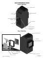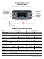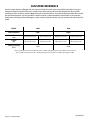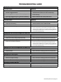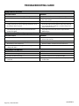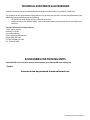
1
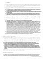
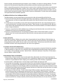
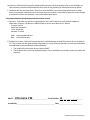
OWNERS MANUAL
We manufacture, test and certify 100% of our wine cooling units in
the USA. By sourcing the best components and closely controlling our
manufacturing processes, we can assure the highest-quality, lowest
defect manufacturing rates in the industry.
Copyright © 2011. CellarCool. All rights reserved.
This manual, the product design, and the design concepts are copyrighted by CellarCool, with all rights reserved. Your rights with
regard to the hardware and manual are subject to the restrictions and limitations imposed by the copyright laws of the United
States of America. Under copyright laws, this manual may not be copied, reproduced, translated, transmitted, or reduced to any
printed or electronic medium or to any machine-readable form, for any purpose, in whole or in part, without the written consent
of CellarCool.
Every effort has been made to ensure that the information in this manual is accurate. CellarCool is not responsible for printing or
clerical errors.
CellarCool reserves the right to make corrections or improvements to the information provided and to the related hardware at
any time, without notice.
Vinothèque and CellarCool are registered trademarks, and ECE is a trademark of CellarCool. All rights reserved.
Mention of third-party products is for informational purposes only and constitutes neither an endorsement nor a
recommendation. CellarCool assumes no liability with regard to the performance or use of these products.
07.03.13
Page 2 | 1-800-343-9463
UFM 070313
TABLE OF CONTENTS
Quick Reference Guide
Unit . . . . . . . . . . . . . . . . . . . . . . . . . . . . . . . . . . . . . . . . . . . . . . . . . . . . . 2
Controller. . . . . . . . . . . . . . . . . . . . . . . . . . . . . . . . . . . . . . . . . . . . . . . . 3
Fan Speed & Specifications. . . . . . . . . . . . . . . . . . . . . . . . . . . . . . . 4
Introduction. . . . . . . . . . . . . . . . . . . . . . . . . . . . . . . . . . . . . . . . . . . . . . . . 5
Receiving & Inspecting The Unit. . . . . . . . . . . . . . . . . . . . . . . . . . . . 6
Quick Start Guide. . . . . . . . . . . . . . . . . . . . . . . . . . . . . . . . . . . . . . . . . . . 7
Preparing the Wine Cellar. . . . . . . . . . . . . . . . . . . . . . . . . . . . . . . . . . . 8
Through-the-Wall Installation
Pre-Installation. . . . . . . . . . . . . . . . . . . . . . . . . . . . . . . . . . . . . . . . . . . 11
Preparing the Installation Location . . . . . . . . . . . . . . . . . . . . . . . 12
Installing the Cooling Unit. . . . . . . . . . . . . . . . . . . . . . . . . . . . . . . . 13
Installing the Drain Line. . . . . . . . . . . . . . . . . . . . . . . . . . . . . . . . . . 15
Drain Line Pump System . . . . . . . . . . . . . . . . . . . . . . . . . . . . . . . . . 16
Ducted Installation
Duct Work Option 1. . . . . . . . . . . . . . . . . . . . . . . . . . . . . . . . . . . . . . 18
Duct Work Option 2. . . . . . . . . . . . . . . . . . . . . . . . . . . . . . . . . . . . . . 19
Ducting Overview. . . . . . . . . . . . . . . . . . . . . . . . . . . . . . . . . . . . . . . . 21
Multi Speed Fan Control. . . . . . . . . . . . . . . . . . . . . . . . . . . . . . . . . . . . 22
Unit Operation. . . . . . . . . . . . . . . . . . . . . . . . . . . . . . . . . . . . . . . . . . . . . . 23
Control Functions. . . . . . . . . . . . . . . . . . . . . . . . . . . . . . . . . . . . . . . . . . . 24
Ultimate FM 8000 Wire Diagram. . . . . . . . . . . . . . . . . . . . . . . . . . . . 26
Maintenance Schedule . . . . . . . . . . . . . . . . . . . . . . . . . . . . . . . . . . . . . 27
Troubleshooting Guide. . . . . . . . . . . . . . . . . . . . . . . . . . . . . . . . . . . . . 28
Technical Assistance & Accessories. . . . . . . . . . . . . . . . . . . . . . . . . 31
Installation Terms and Conditions. . . . . . . . . . . . . . . . . . . . . . . . . . 32
www.whisperkool.com | Page 1
QUICK REFERENCE GUIDE
Front / Side View
Exhaust Collar
Rear Intake Plenum
Supply
Air Sensing Probe
Controller
Power Inlet
Return
Fan Speed Control
Condensate Pump
Access Panel
Rear / Side View
Exhaust Plenum
Drain Port
Rear Intake Plenum
Unattached
Intake Plenum
Register
Power Inlet
Filter
Page 2 | 1-800-343-9463
UFM 070313
QUICK REFERENCE GUIDE
Controller Layout
Refer to page 24 for complete listing of buttons and symbols.
Menu Navigation
& Value Increase
*Press and hold
to manually enter
anti-frost mode.
Power On/Off
(hold for approx. 3 seconds)
& Escape
Probe Values &
Alarm Folder
Menu Navigation
& Value Decrease
*Press and hold to
enter the parameter
menu.
Compressor On
Alarm is Present
Unit is in Anti-Frost Mode
Temperature Measurement
Fans are On
ULTIMATE FM UNIT SPECIFICATIONS
Model
Ultimate FM 8000
Low Speed
Ultimate FM 8000
High Speed
2000
2000
Cellar Size (cu. ft.)
Dimensions
15 1/4”w x 36.25”h x 16”d
BTUh with 90° air entering
the Condenser Coil
CFM
Refrigerant
5610
275 Evaporator Side
6206
257 Condenser Side
303 Evaporator Side
279 Condenser Side
R-134a
Compressor HP
1/2+
1/2+
131
131
Voltage Rating (20 amp 120V
dedicated circuit required)
Weight (lbs)
AMPS (Starting/Running)
dBA
38.6 Starting
9.2 Running
40 Starting
9.5 Running
65 Evaporator Side
54 Condenser Side
68 Evaporator Side
56 Condenser Side
Drainline
1/4” I.D
Installation
Partially Ducted System. Maximum Ducted feet: 15’
Thermostat
Digital Control Display
Temp. Delta
55°F Temperature differential between the cellar temperature and condenser air intake temperature.
Warranty
2 year parts and labor
www.whisperkool.com | Page 3
FAN SPEED REFERENCE
Your fan speed selection will depend on the amount of heat that needs to be removed from the cellar. Fan speed
selection will depend on the cellar size, insulation factor, door seal and desired wine temperature. When initially
installing the unit, set the fan speed to High setting for a quick chill down. Once the temperature of the cellar reaches
the desired temperature, you may be able to select a lower fan speed to handle the normal load. In the event the
temperature outside goes above 90 degrees, (when exhausting to the outside) you may need to select the higher fan
speed.
Model
8000
8000
Speed Selection
Low
High
Air Flow
275 Evaporator Side
257 Condenser Side
303 Evaporator Side
279 Condenser Side
Sound
65 Evaporator Side
54 Condenser Side
68 Evaporator Side
56 Condenser Side
(CFM)
(dBA)
Cooling Capacity
(BTU/h)
5610
6206
* To get a feeling for decibels, a food blender at 3ft is 90 dBA, garbage disposal at 3ft is 85 dBA, vacuum cleaner at
10ft is 75 dBA, normal speech at 3ft is 79 dBA, dishwasher in the next room is 55dBA, Quiet night is 35dBA
Page 4 | 1-800-343-9463
UFM 070313
INTRODUCTION
Customer Service
Thank you for purchasing a CellarCool Ultimate FM Series cooling unit. We strive to provide the highest quality
products and the best possible customer service. If you have any questions about your CellarCool unit, please call us
at 1(800) 343-9463 or visit cellarcool.com.
Using the Manual
This User’s Manual is intended to assist in the proper installation and maintenance of the CellarCool cooling unit. In
order to ensure the longevity of your cooling unit, the equipment should be installed properly and have a proper
care and maintenance schedule. Please read and review this manual carefully and keep it for future reference.
What Is the CellarCool Cooling Unit?
The CellarCool unit is a specialized refrigeration unit designed for one purpose only: to maintain the optimal
temperature and humidity levels conducive to the proper storage and aging of fine wines. It is a self-contained
cooling unit designed to be used as a forced-air partially ducted system.
How Does the CellarCool Ultimate FM Series Work?
The CellarCool unit is especially designed for the use and application to maintain optimal conditions for wine storage
and aging. The unit is fully self-contained and is designed to be installed completely inside the wine cellar. The unit
draws air in from an adjacent room and exhausts heat via duct work to an acceptable area. This provides the ease
of installation of a through the wall system, while keeping unwanted noise and heat to a minimum. All Ultimate FM
units are temperature controlled via a Air Sensing probe and come standard with an advanced digital thermostat.
Temperature Setting
The CellarCool Ultimate FM unit can be set at any temperature within the acceptable wine-aging range of 50°F to
70°F. It is designed to cool up to 55°F cooler than the ambient temperature of the space to which it is exhausting.
www.whisperkool.com | Page 5
RECEIVING & INSPECTING THE UNIT
Receiving and Inspecting the Unit
• Lift only at the designated hand hold locations on the shipping container or fully support the unit from
•
•
•
•
underneath. A shipment may include one or more boxes containing accessories.
Before opening the container, inspect the packaging for any obvious signs of damage or mishandling.
Write any discrepancy or visual damage on the Bill of Lading before signing.
Place the box containing the CellarCool unit on a tabletop to prepare it for testing prior to installing.
Sit upright for 24 hours.
Note: CellarCool Ultimate FM units are manufactured in the USA and tested prior to shipment.
Review the Packing Slip to Verify Contents
• Check the model number to ensure it is correct.
If any items listed on the packing slip do not match your order information,
contact CellarCool Customer Service immediately.
Check the Box for the following contents:
• Ultimate FM Cooling Unit
• Ultimate FM Register
• Ultimate FM Intake Plenum • Filter
Accessory Kit One:
• CellarCool Ultimate FM Series Owner’s Manual
• 8’ Power Cord
• Air Sensing Temperature Probe (Standard Unit)
• 10’ Drain Line
• Anti-Siphon device
• Tubing adapter
Please leave the CellarCool unit in its original box until you are ready for installation. This will allow you to move the
product safely without damaging it. When you are ready to remove the product from the box, refer to the installation
instructions.
TIP: Save your box and all packaging materials. They provide the only safe means of transporting/shipping the unit.
Page 6 | 1-800-343-9463
UFM 070313
QUICK START GUIDE
This guide is meant to serve as a quick reference for installation of the CellarCool unit. The remainder of this Owner’s
Manual will provide more detailed information and instructions.
Upon receiving the CellarCool unit:
1. Inspect the unit before installation. If damage is found, please contact your distributor or CellarCool Customer
Service at 1.800.343.9463 ext 799.
2. The unit should remain in an upright position for 24 hours prior to operation.
3. The CellarCool unit requires a dedicated 115-volt 20-amp circuit. Use a surge protector with the CellarCool unit.
Do not use a GFI (Ground Fault Interrupter) line.
4. The unit is designed to gently cool down the temperature of the cellar over time by cycling cooler and cooler air
throughout. Test the unit prior to installation. Operate unit for twenty minutes. While the unit is running and
working properly, the air discharged from the front should be 10 - 15°F cooler than the air in the room. This
means that in an environment where the air is 80°F, the unit will discharge air that is 65-70°F.
5. It is REQUIRED to install a drain line to remove condensation from the unit.
6. The CellarCool unit is intended for use in properly designed and constructed wine cellars. Hire a professional
wine storage consultant with a valid contractor’s license to build your wine cellar. Refer to the “How to Build a Wine
Cellar” video available on the CellarCool website at www.cellarcool.com.
7. Install the Intake Plenum as shown on (page 13).
8. Install duct work as shown on (pages 17-19).
9. Install Drain Line as shown on (page 15).
10. Plug in the cooling unit.
Never try to open the CellarCool unit, repair it yourself, or use a service company without CellarCool’s
authorization. This will void your warranty.
If you encounter a problem with your CellarCool unit, please refer to the Troubleshooting Guide. If you have any
further questions, concerns, or need assistance, please contact CellarCool Customer Service at 1.800.343.9463 ext.
799. Please be sure all testing has been completed prior to contacting Customer Service. Please have your results
ready for your representative.
www.whisperkool.com | Page 7
PREPARING THE WINE CELLAR
The performance and life of your CellarCool unit is contingent upon the
steps you take in preparing the wine cellar.
Note: Improperly preparing your enclosure or incorrectly installing your CellarCool
unit may cause unit failure, leaking of condensation, and other negative side effects.
IT IS HIGHLY RECOMMENDED THAT YOU OBTAIN THE ASSISTANCE
OF A WINE STORAGE PROFESSIONAL.
Wine storage professionals work with licensed contractors, refrigeration technicians, and racking companies to build
well-insulated, beautiful, and protective wine cellars. CellarCool has put together some useful tips to assist in the
installation process. Our recommendations are meant to act as a guide in the process of building a proper enclosure.
Your intended location may have specific needs that we do not address.
How to Build a Wine Cellar Instructional Video
CellarCool has a construction tutorial available on line at our website: www.cellarcool.com. This tutorial will walk you
through the steps of constructing a properly built wine cellar and the installation of our CellarCool product line.
Wall & Ceiling Framing
Build wine cellar walls using standard 2x4 or 2x6 construction methods and ceiling joists following the guidelines of
local and state codes in your area. As a general rule, the thicker the walls and the higher the insulation value in your
cellar, the better it will be at maintaining a consistent temperature.
Insulation
Insulation is REQUIRED with the use of the CellarCool product. Standard fiberglass or rigid foam insulation is normally used in cellar construction or, in some cases, “blown-in” insulation is used. It is very important that all walls and
ceilings are insulated to keep the cellar temperature as consistent as possible during the summer and winter months.
The R-value, or quality of insulation, is determined by the rate at which heat passes through the insulation. The
higher the R-value, the more resistant the insulation is to conducting heat. Using higher R-values in insulation will
lower your operating costs and unit run time. (R-13 minimum, R-19 recommended, R-30 for ceiling and exterior walls.)
Vapor Barrier
A vapor barrier is REQUIRED to prevent the intrusion of water vapor so that the cellar can be kept at the correct
temperature and humidity. 6 mm plastic sheeting (recommended) should be applied to the warm side of the cellar
walls. The vapor barrier must also be applied to the outside walls and ceiling. If it is impossible to reach the outside,
then the plastic must be applied from within the cellar. The most common method is to wrap the entire interior,
leaving the plastic loose in the stud cavity so the insulation can be placed between each stud. All of the walls and
ceiling must be wrapped in plastic for a complete vapor barrier.
In areas of high humidity, such as Southern and Gulf States, the vapor barrier will prevent infiltration of warm moist
air. The moist air can cause mold to form, and standing water in drain pans promote microbial and fungal growth that
cause unpleasant odors and indoor air quality problems. If mold is found, remove it immediately and sanitize that
portion of the unit.
Page 8 | 1-800-343-9463
UFM 070313
Cooling Unit
Keep Clear
Unobstructed Airflow
Unobstructed airflow to and from the unit is critical for the unit’s overall performance and life-span. A
minimum three-foot clearance (five foot is ideal) area is crucial. The air the fans blow needs to circulate and either
dissipate or absorb heat from the space, the more air to exchange the more efficient the unit will operate.
Note: Avoid attempting to camouflage the unit. This will restrict airflow and thus the unit’s ability to work efficiently.
Door and Door Seal
An exterior grade (1 3/4”) door must be installed as a
cellar door. It is very important that weather stripping is
attached to all 4 sides of the doorjamb. A bottom “sweep”
or threshold is also required. The door must have a very
good seal to keep the cool cellar air from escaping out
of the cellar. One of the most common problems with
cooling units running continually is due to the door not
sealing properly. In cases where glass doors are used
and the room size is close to the recommended unit
size, the next larger size CellarCool should be used.
This will compensate for the insulation loss due to the
lower insulating rating of glass.
www.whisperkool.com | Page 9
Ventilation
The necessity of dissipating heat away from the unit is critical to the unit’s performance and cannot be overstated. As
the unit operates and cools, a greater amount of heat is generated on the exhaust side of the unit. Adequate ventilation
is required in order to dissipate heat away from the unit. If ventilation is inadequate, the exhaust will heat up the
area or room and adversely affect the unit’s ability to cool. In some cases, it may be advisable to install a vent fan to
dissipate heat within the exhaust area on the backside of the unit. However, you must have a fresh air inlet as well.
Note: If you are unsure about having adequate ventilation in your install location, please
contact us to assess your specific installation at [email protected] or 1.800.343.9463.
Ambient Temperature Factor
The cooling unit has the ability to cool a wine cellar efficiently to 55°F as long as the ambient temperature of the
area that it is exhausting to does not exceed 110°F. Therefore, you want to exhaust the unit in a room which will not
exceed 110°F. Otherwise the unit will not have the capacity to keep the wine at a desirable 55°F.
Warning, allowing your unit to operate in high ambient temperatures for extended
periods of time will greatly decrease the life of your unit and void your warranty.
Page 10 | 1-800-343-9463
UFM 070313
PRE-INSTALLATION
TEST THE UNIT PRIOR TO INSTALLATION
To prepare it for testing before installation in wall:
• Unit needs to be in the upright position for 24 hours before starting.
• Remove unit from box
• Plug in unit to electrical outlet
• Turn on to test (see #4 on the Quick Start Guide for details).
• Turn off after test
Electrical Needs
The CellarCool Ultimate FM Unit requires a dedicated 115-volt 20-amp circuit. The unit draws a large amount of
amps at initial start up. By designating a dedicated circuit breaker, you will guarantee the unit has enough power to
run effectively. Contact an electrician for assistance with the installation of this dedicated electrical circuit:
• Match the electrical outlet to the plug provided on the CellarCool unit.
• Provide a dedicated circuit and wiring for the unit.
Plug your CellarCool unit into a surge protector or power conditioner. As with any sensitive electrical equipment,
the CellarCool electrical equipment may be damaged by power surges and spikes. Power surges and spikes are not
covered under warranty.
WE RECOMMEND THAT YOU DO NOT USE A GROUND FAULT INTERRUPTER (GFI) WITH THIS PRODUCT.
Electrical Inlet
The unit is equipped with a power inlet which is located on the right side of the cooling unit and is labeled in the
Quick Reference Guide on page 2. The power inlet is to be connected inside of the cellar.
In case the unit should lose power, check the home/main circuit breaker. If the unit does not respond properly, refer
to the Troubleshooting section.
www.whisperkool.com | Page 11
PREPARING THE INSTALLATION LOCATION
Through-the-Wall
Minimum Tools Needed
Level
Hammer
Screwdriver
Saw
Locate the desired installation location. Using a stud finder, locate the studs
on either side.
Place the unit against the wall to determine the height of the Intake Plenum
on the rear of the Cooling Unit.
Using a level and a pencil, make an outline of a 12 1/4” square in between the
two studs to provide an entry for the two Intake Plenums pieces.
Using a saw, cut out the outlined square. Be careful not to cut into any studs,
electrical, or plumbing.
12 1/4”
If present, only remove the insulation covering the area of the cut-out.
Now you have to make the same hole on the other side of the wall. Since you
already have one hole, this is an easy process. Using a nail, mark all four corners
of the first hole by making nail holes through the sheetrock. Then on the other
side of the wall, connect the holes with a pencil mark and cut.
12 1/4”
Though there are still steps prior to the installation of the unattached Intake
Plenum, check to see that the Plenum fits snugly through the cut-out area.
Place the Register on the unattached Intake Plenum. Mark the holes that will
be drilled.
Pre-Drill the holes on the unattached intake Plenum.
Page 12 | 1-800-343-9463
UFM 070313
INSTALLING THE UNIT
From outside the cellar:
1. Apply air-tight sealant or caulking on the area of the unattached Intake Plenum that will contact the wall (as shown
in Figure 1).Make sure to seal all cracks and gaps. This will prevent heat transfer between the cellar and the adjacent
area.
2. Slide in and secure the unattached Intake Plenum to the wall from out side of the cellar using sheetrock anchors or
wood screws when going into a stud.
FIGURE 1
FIGURE 2
From inside the cellar:
3. Position the Rear Intake Plenum through the cellar wall. This will provide the intake on the condenser side of the
unit with fresh air.
It is not required to place the cooling unit directly against the cellar wall, however, having the unit as close to the wall
as possible is recommended.
FIGURE 3
www.whisperkool.com | Page 13
INSTALLING THE UNIT
From outside the cellar:
Make sure to remove all insulation or debris left inside either Plenum prior to sliding the cooling unit against the
cellar wall and connecting the Intake Plenum and the rear unattached Intake Plenum.
4. From outside the cellar seal all cracks and gaps where the two Intake Plenums meet on the inside of the
unattached Intake Plenum with an air-tight sealant or caulking to prevent heat transfer between the cellar and the
adjacent area (as shown in Figure 4).
5. Attach the Register to the unattached Intake Plenum.
6. Insert the Filter into the Register.
7. Plug in the Cooling Unit when finished ducting the exhaust on the condenser side of the unit.
FIGURE 4
Note: If you use decorative moulding, it should be attached to the walls and never to the cooling unit itself.
The moulding itself should be removable incase the unit needs servicing.
Page 14 | 1-800-343-9463
UFM 070313
DRAIN LINE
Condensation Drain Line Tube
The condensation drain line tube is used to remove excess condensation from the unit to a proper discharge location.
It is important that the drain line tube is properly connected and used to prevent leakage and other problems
associated with excess condensation.
Failure to use the condensation drain line tube will void the warranty on the unit.
Drain Line
During operation, the cooling unit will strip
excess condensate from the air in order to
maintain the proper level of humidity within the
cellar. Thus the drain line will prevent overflow
and leaking by allowing for discharge of the
additional condensate.
Connect the Drain Line Tube to the Drain Port on
the Top of the Cooling Unit. Routing the Drain
Line to the attic and then to a dispense area is
recommended. The Ultimate FM Cooling Unit will
Pump the excess condensate through the Drain
Line Tube.
Do not rout the drain line more than 30 vertical ft.
If the outlet of the drain line is below the base of
the unit, install the anti-siphon device as shown
in (Figure 5).
Anti-Siphon
Device
FIGURE 5
Failure to install the drain line voids the warranty.
To prevent mold from growing, allow the drain
line to hang above the water line.
WRONG: Drain line is under water.
www.whisperkool.com | Page 15
DRAIN LINE PUMP SYSTEM
CORRECT: Typical sequence of operation for correct Discharge Hose installation with Anti-Siphon Device
1. Drain pan fills with water which flows into reservoir. Intake hose between reservoir and pump is empty (filled with
air).
2. Raising water lifts float, activating pump, which self primes by drawing water up from reservoir. During this period
the pump is operating hot and dry and will click loudly. Once the air in the intake hose has been purged, water
entering the pump cools and lubricates it so that the clicking noise becomes a low hum. Water flows through the
pump and out of the discharge hose.
3. Water level in the reservoir has now receded enough to lower the float which deactivates the pump, however, since
an Anti-Siphon Device is included in the discharge hose, atmospheric pressure is equalized at both ends of the hose
system so the siphoning effect cannot occur and THE INTAKE HOSE REMAINS FILLED WITH WATER.
4. The drain pan again fills up with water which flows into the reservoir and activates the pump. THE INTAKE HOSE
IS ALREADY FILLED WITH WATER so no air is sucked in, and the pump is immediately cooled and lubricated. NO
CLICKING NOISE IS HEARD.
PUMP
PUMP
1
AIR GAP
2
AIR GAP
MAXIMUM 2”
MAXIMUM 2”
MINIMUM 6”
DRAIN PAN
RESERVOIR
MINIMUM 6”
DRAIN PAN
3/4” PVC OR
COPPER PIPE
BREATHER TUBE
RESERVOIR
PUMP
3
PUMP
AIR GAP
ATMOSPHERE
PRESSURE
4
AIR GAP
MAXIMUM 2”
DRAIN PAN
RESERVOIR
NOTE: THIS APPLIES ONLY TO
INSTALLATIONS WHERE THE POINT
AT WHICH THE CONDENSATE WATER
EMERGES FROM THE DRAIN HOSE
OR PIPE IS BELOW THE DRAIN PAN IN
THE EVAPORATOR.
IF THE END OF THE PUMP
DISCHARGE HOSE OR PIPE IS ABOVE
THE LEVEL OF THE DRAIN TRAY IN
THE EVAPORATOR NO SIPHONING
CAN OCCUR AND AN ANTI-SIPHON
DEVICE IS NOT REQUIRED.
MAXIMUM 2”
MINIMUM 6”
ATMOSPHERE
PRESSURE
3/4” PVC OR
COPPER PIPE
BREATHER TUBE
THE PUMP IS NOW OPERATING
ENTIRELY WITHIN NORMAL
PARAMETERS AND IS IN NO DANGER
OF OVERHEATING OR FAILING.
MINIMUM 6”
DRAIN PAN
BREATHER TUBE
Page 16 | 1-800-343-9463
3/4” PVC OR
COPPER PIPE
RESERVOIR
BREATHER TUBE
3/4” PVC OR
COPPER PIPE
UFM 070313
DRAIN LINE PUMP SYSTEM
INCORRECT: Failure to follow correct Discharge Hose installation will damage pump.
1. Drain pan fills with water which flows into reservoir. Intake hose between reservoir and pump is empty (filled with
air).
2. Raising water lifts float, activating pump, which self primes by drawing water up from reservoir. During this period
the pump is operating hot and dry and will click loudly. Once the air in the intake hose has been purged, water
entering the pump cools and lubricates it so that the clicking noise becomes a low hum. Water flows through the
pump and out of the discharge hose.
3. Water level in the reservoir has now receded enough to lower the float, deactivating the pump. However, the
weight of the water in the discharge hose plus atmospheric pressure at the drain pan outlet forces the water
remaining in the intake hose to continue flowing out through the pump until the reservoir, intake hose, pump and
discharge hose are completely empty, at which point the siphoning stops.
4. As the evaporator produces more condensate, the drain pan again fills up with water which flows into the reservoir.
Since the intake hose is filled with air again, the cycle repeats itself.
PUMP
PUMP
1
THE NEXT TIME THE PUMP STARTS
UP DRY, IT MAY RUN FOR 11
SECONDS BEFORE IT COOLS DOWN
THE NEXT TIME 12 SECONDS
AND SO ON. ALSO WHILE THIS IS
OCCURRING, THE PUMP IS CLICKING
LOUDLY. THIS IS ACCEPTABLE
DURING THE INITIAL START UP
PHASE, BUT NOT ACCEPTABLE
DURING SUBSEQUENT OPERATIONS
OF THE PUMP.
2
DRAIN PAN
DRAIN PAN
RESERVOIR
RESERVOIR
BREATHER TUBE
BREATHER TUBE
PUMP
3
PUMP
4
ATMOSPHERE
PRESSURE
DRAIN PAN
RESERVOIR
DRAIN PAN
BREATHER TUBE
RESERVOIR
BREATHER TUBE
RESULT: EVERY TIME THE PUMP
RUNS HOT AND DRY, IT SUSTAINS
A SMALL AMOUNT OF DAMAGE
WHICH CAUSES PREMATURE WEAR.
WHEN YOU CONSIDER THAT
THIS WILL OCCUR A NUMBER
OF TIMES EVERY DAY OF THE
COOLING SEASON IT IS EASY
TO SEE THAT THE DAMAGE WILL
RAPIDLY ACCUMULATE. IF THE
PUMP IS ALLOWED OPERATE IN
THIS CONDITION REPEATEDLY, THE
NOISY PERIOD WILL GET LONGER
AND LONGER OVER THE COOLING
SEASON UNTIL THE CUSTOMER
COMPLAINS OR THE PUMP
EVENTUALLY FAILS.
THIS CAN EASILY BE AVOIDED
BY INSTALLING THE DISCHARGE
HOSING CORRECTLY WITH AN
ANTI-SIPHON DEVICE WHICH WILL
EQUALIZE THE ATMOSPHERIC
PRESSURE AND ELIMINATE THE
SIPHONING.
www.whisperkool.com | Page 17
INSTALLING THE DUCT WORK
Building a Facade
The Ultimate FM Cooling Unit is set up to have a variety of Ducting Installation Options. The exhaust may be ducted
into the attic or out to the exterior of the house through the attic. The first option to consider is using a standard
6”x14” Duct Boot and 8” diameter duct work for the exhaust followed by building a facade around the duct work.
Figure 5 below is an example that may be followed to create a facade to extend to the Ceiling using: 1/2” Plywood,
1/2” Drywall (2) 2x2, (2) 3x3.
“
“
“
“
“
Measure the space between the
cooling unit and the wall and add
the distance to these dimensions for
the total length.
FIGURE 5
Page 18 | 1-800-343-9463
UFM 070313
INSTALLING THE DUCT WORK
Custom Duct Work
Another Option that might be considered is building Insulated Custom Duct Work. Figure 6 below is an example
that may be followed to create Insulated Custom Duct Work to extend to the attic using 1/2” Plywood, 1/2” Insulation
Board and (24) Angle Brackets.
Ducting Information
When Ducting the Exhaust away from the Cooling Unit, custom Ducting will be sufficient if it follows these
recommendations:
• Custom Ducting is insulated so that the warm exhaust air in the duct does not affect the air in the Cellar.
• The surface area of inside the duct is greater than or equal to 51 sq. in.
• The Duct Work follows the General Duct Recommendations on page 21.
“
“
“
Measure the space between the
cooling unit and the wall and add
the distance to these dimensions for
the total length.
“
FIGURE 6
www.whisperkool.com | Page 19
NOTES
Page 20 | 1-800-343-9463
UFM 070313
DUCTING OVERVIEW
Use of Ductwork
Use ductwork to connect the Exhaust Collar on the top of the cooling unit to the desired exhaust area. Use only
insulated ductwork to minimize cooling losses and reduce noise.
Note: Do not exceed a total of 15’ for the length of ductwork.
Avoid crimping the flexible ducts. This chokes down the inside area and reduces the airflow causing the unit to
operate improperly. Be sure all duct work is insulated.
DO NOT ALLOW FLEXIBLE DUCTING TO GET SQUEEZED OR ALLOW THE INSIDE
DIAMETER TO DECREASE DUE TO VERY SHARP TURNS.
General Duct Recommendations
• Use a 6”x14” duct boot to connect to the Exhaust Collar (when using standard duct work).
• Provide support for the flexible duct to prevent sags and bends.
• Ultimate FM 8000 Duct Size: 8” dia.
• Stretch out the duct to make a smoother interior which reduces air resistance.
• Maximum duct length is 15’.
• For 90° bends, use a 90° adjustable elbow.
• No more than two 90° bends. Sweep 90° bends are recommended rather than sharp 90° bends.
• Generously apply duct sealant to all metal seams to fill in gaps that can leak air. Allow sealant to dry until firm
to the touch before applying fiberglass insulation.
• Do not squeeze or reduce the inside diameter of the ducts as this will reduce airflow.
• Use short and straight ductwork where possible.
• Check that all fan blades move freely.
• Keep air paths free of loose foreign objects and debris.
Do not: Locate the Exhaust where it will be blocked for any reason.
www.whisperkool.com | Page 21
MULTI SPEED FAN CONTROL
Designed for wine cellars up to 2000 cubic feet, the Ultimate FM 8000 features multi-speed fans with a “high”
setting for maximum performance in high-temperature (+110°F) environments and a “low” setting for superquiet operation.
Fan Speed Selector Switch (Low/High): The cooling unit fans may operate on two speed settings: Low and
High. For optimum sound and energy efficiency, select the lowest fan speed that will maintain the desired cellar
temperature. If the relative humidity is low, a higher fan speed will cause less moisture to be removed during
cooling. High speed is recommended for initial cellar cool down.
Your fan speed selection will depend on the amount of heat that needs to be removed from the cellar and the
application of the unit. Fan speed selection will depend on the cellar size, insulation factor, door seal and desired
wine temperature. When initially installing the unit, set the fan speed to the Highest setting for a quick chill down.
Once the temperature of the cellar reaches the desired temperature, you may be able to select the lower fan speed to
handle the normal load. In the event the temperature of the intake air on the condenser side goes above 90 degrees,
you may need to select the higher fan speed.
Model
8000
8000
Speed Selection
Low
High
Air Flow
275 Evaporator Side
257 Condenser Side
303 Evaporator Side
279 Condenser Side
Sound
65 Evaporator Side
54 Condenser Side
68 Evaporator Side
56 Condenser Side
(CFM)
(dBA In Cellar / Out of Cellar)
Cooling Capacity
(BTU/h)
Page 22 | 1-800-343-9463
5610
6206
UFM 070313
UNIT OPERATION
Initial Start-Up:
When power is applied to the unit, the control will briefly
display all symbols, and the Compressor symbol will be
displayed (if unit is calling for cooling). There may be a brief
delay prior to the evaporator and condenser fans turning on.
Set Point:
The set point is set from the factory (Cellarcool) at 55°. It can
be adjusted by the customer between 50° and 70° in one
degree increments.
Cooling Operation:
Cooling is activated once the Air Sensing probe senses
a temperature that is 1° greater than the set point. The
controller then energizes the compressor relay which
activates the compressor. The evaporator and condenser
fans operate with the compressor. The unit provides cooling
until the Air Sensing probe senses the set point. At this
point the compressor relay is de-energized which stops
the compressor. The evaporator and condenser fans will
continue to run for 1 minute to re-evaporate any moisture
from the evaporator coil and reduce the head pressure.
Humidity Features:
The FDC parameter can be increased to allow the evaporator
and condenser fans to run for a longer period of time after
the compressor turns off, allowing more moisture to be reevaporated into the cellar.
Defrost/Anti-frost:
When the evaporator probe senses a temperature of
26 degrees for 5 minutes, the unit will go into Anti-frost
mode. This will shut down the compressor and allow the
evaporator and condenser fans to run to evaporate any frost
accumulation on the coil. The compressor will remain off
until the evaporator coil reaches 40°, or for a maximum of 10
minutes. The unit will then return to normal operation.
If the evaporator is not above 26 degrees after the anti-frost
sequence has ended, the red error light will display in the
upper right corner. Alarm “Ad3” will be recorded in the alarm
folder, meaning that the anti-frost sequence ended based
on time. The unit will run for 5 minutes and then enter
another Anti-Frost cycle. This sequence will continue until
the evaporator temperature increases above 26°.
Display:
The Air Sensing probe temperature is displayed by default.
“Def” is displayed during anti-frost. The Air Sensing probe
and evaporator probe temperatures can be accessed by
pushing the set button and scrolling through PB1 (Air
Sensing probe) and PB2 (evaporator probe).
Safety Features:
Once the compressor relay is de-energized the controller
must wait 5 minutes before re-energizing the relay. This
prevents the compressor from repeatedly turning off and
on. If the unit is calling for cooling during this time, the
compressor symbol will blink indicating that cooling is
needed but the control is waiting for the anti-short cycle
delay.
In the event of a faulty Air Sensing probe, the compressor
will cycle off for 10 minutes and on for 40 minutes. E1 will
be displayed on the screen.
Alarms:
If the Air Sensing temperature reaches 4 degrees above the
set point, a red light will blink in the upper right corner of
the display. The set button can then be pressed to reach
the alarm menu. The menu will display “AH1” indicating a
high Air Sensing temperature. The same thing will happen
if the Air Sensing temperature reaches 4 degrees below the
set point, except the alarm will read “AL1”. These alarms will
not display for the first 10 hours after the unit is turned on
to allow the cellar to reach temperature. They will also wait
one hour after an anti-frost cycle before displaying.
In the event of a faulty evaporator probe E2 will flash on the
screen intermittently. The red alarm light will be displayed
in the upper right corner. The unit will go through one antifrost sequence every 24 hours.
Press the set button and enter the Al folder to view any
current alarms that are not flashing on the display.
In the event of a high water alarm the compressor will turn
off, the alarm will sound and “Opd” will be displayed in the
alarm folder. The unit will continue normal operation once
the pump has removed enough water to clear the high
water alarm.
“Def” will be displayed during anti-frost. If the anti-frost
sequence is less than 5 minutes, the control will not allow
the compressor to start until 5 minutes has elapsed. This is
to prevent short cycling of the compressor.
Holding down the up button for approximately five seconds
manually starts the Anti-frost sequence, but only if the
evaporator is below 40 degrees (defrost end temperature).
If the evaporator is above 40 degrees, the display will blink
three times and continue normal operation.
www.whisperkool.com | Page 23
CONTROLLER FUNCTIONS
Button/Symbol
Normal Functions
ON/OFF •
•
Up and Down •
•
SET •
•
•
•
•
Press and hold the on/off button for approximately 3 seconds to turn the unit on or off.
Note: This does not disconnect power from the unit. In order for the power to be shut off from
the unit, the power cord must be unplugged from the wall receptacle.
This button also serves as an escape button.
Use these buttons to scroll up or down a menu.
Press and hold the up button for approximately five seconds to manually start the Anti-frost
sequence. The Anti-frost sequence will begin, but only if the evaporator is below 40 degrees. If
the evaporator is above 40 degrees, the display will blink three times, signalling that an Anti-frost
cycle is not needed, and the unit will continue normal operation.
Press the set button once to view the set point, temperature of the evaporator and actual Air
Sensing temperature as well as any alarms.
Once the set button is pressed “SEt” will be displayed. Press the up or down arrows to scroll
through Pb1, Pb2.
SEt
Set Point
Pb1
Liquid Temperature
Pb2
Evaporator Coil Temperature
Press the set button again to view any of these values.
To change the set point, press the set button when “SEt” is displayed on the screen. The current
set point will be displayed. Use the up or down arrows to change the set point to the desired
temperature. Press the set button again once the desired temperature is reached.
Hold the set button for approximately 5 seconds to enter the CPSM (Customer Preference
Selection Mode) menu. (CPSM detail on next page)
Snowflake Constant - Unit is in cooling mode and the compressor is running.
Blinking - The unit is calling for cooling, but must wait 5 minutes before restarting the compressor.
This 5 minute delay serves as an anti-short cycle for the compressors protection.
Dripping Snowflake Unit is in Anti-frost mode. The evaporator and condenser fans are running to evaporate any frost
which may have formed on the evaporator coil.
Fan The evaporator and condenser fans are on.
Alarm The Alarm symbol is shown and a audible buzzer will sound when the unit encounters an issue that
needs attention, the displayed alarm codes are explained below. To silence the buzzer press any
button, the alarm code will remain displayed until corrected.
Page 24 | 1-800-343-9463
UFM 070313
Alarm Codes
Message
“E1”
“E2”
Cause
Solution
Faulty Air Sensing Probe
Connection
1. Check Air Sensing Probe attachment at circular connector.
2. Check Air Sensing Probe connection at the back of controller.
Defective Air Sensing Probe
Replace the Air Sensing Probe.
Faulty Evaporator Probe
Connection
Check Evaporator Probe connection at the back of controller.
Defective Evaporator Probe
Replace the Evaporator Probe.
“AH1”
The Air Sensing probe is
1. Allow time for the wine to reach the desired temperature.
sensing a temperature that is 2. Make sure all windows and doors are closed and have a proper seal.
4° above the set point
3. Follow the procedures in the pre-installation instructions to test the unit for proper
cooling.
“AL1”
1. Make sure unit is not in cooling mode. (the snowflake symbol will not be lit)
The Air Sensing probe is
sensing a temperature that is 2. Add heat to the room until the wine reaches the desired temperature.
4° below the set point
“Ad3”
Anti-frost ended on time-out 1. Check the evaporator coil for ice buildup. Unplug the unit and allow coil to thaw
before re-starting.
2. Make sure the room to which the unit is exhausting is not less than 60°.
3. If unit continues to go into continuous anti-frost cycles (every 5 minutes), call
customer service for more troubleshooting information.
“Opd”
Water level is too high
1. Check drain line for debris & kinks
2. Check power supply to pump
3. Make sure pump & float are level
CPSM (Customer Preference Selection Mode)
Press and hold the set button for approximately 5 seconds to enter the CPSM menu.
“Fdc” will be displayed on the screen. Use the down arrow to access the following parameters.
Fdc This parameter is set to 1 from the factory which should provide adequate relative humidity for the
Humidity Management/ cellar. An increase in this parameter will increase the Humidity Enhancement (%RH). This parameter
Enhancement should not be adjusted below 1. Adjustments should be made in increments of 5, with a maximum of
15 and a minimum of 1. After any adjustment to Humidity Enhancement you should wait a minimum
of three days before making any additional adjustments. This will allow the cellar sufficient time to
acclimate to the new setting.
PA2 No adjustable settings in this parameter.
tab No adjustable settings in this parameter.
Rel No adjustable settings in this parameter.
loc Change this parameter from “n” to “y” to lock the keyboard from changes to the set point.
ddd Select one of these numbers to display your preference:
0 = Set Point
1 = Air Sensing Probe Temperature
2 = Evaporator Probe Temperature
3 = Condenser Probe Temperature
“CA1” Use this parameter to calibrate the Air Sensing probe to a known temperature. This parameter can be
adjusted between -12°F and 12°F.
Example:
Air Sensing temperature reading = 58°F
Known temperature reading = 55°F
CA1 parameter setting to match known temperature = -3
www.whisperkool.com | Page 25
Blue
Black
Gray
Purple
Red
Condensate
Pump
3
NC
7
4
C
8
2
NO
6
Blue
White
Blue
Blue
Green
Green
Green
Gray
Evap.
Fan
Gray
d
Re
Capacitor
Red
White
Brown
t
Compressor
al
utr
Ne
Cond.
Fan
nd
ou
Gr
Ho
1
COMP
0
Crankcase
Heater
8 9 10 11
Black
Black
Orange
Green
Eliwell 974
White
1 2 3 4 5 6 7
(+)
Black
Green
White
Black
Black
Brown
White
2 Way F.S.
2
1
3
Capacitor
UFM 070313
Page 26 | 1-800-343-9463
White
Black
(-)
ULTIMATE FM 8000 WIRING DIAGRAM
Bl
ac
k
MAINTENANCE SCHEDULE
Monthly
1. Check Coils
2. Check for unusual noise or vibration
3. Check the drain line to see if it is above the waterline if draining into a vessel.
Quarterly 1. Clean Coils
2. Replace Filters on the duct work.
3. Check the drain line pump and thoroughly clean the reservoir, filter and float with an
antibacterial cleansing solution.
4. All drain line hoses should be checked for leaks.
Annually
1. Replace filters if worn or plugged beyond cleaning.
2. Use a vacuum with brush attachment to clean coils. Be careful not to crush coil fins
when cleaning.
3. Inspect for corrosion.
4. Check wiring connections and integrity of cords.
5. Examine duct work for cracks or possible leaks.
6. Pour a 50/50 bleach solution into the drain line every spring.
www.whisperkool.com | Page 27
TROUBLESHOOTING GUIDE
Unit has ice forming on the Evaporator
Possible Cause
Solution
Evaporator coil is dirty.
Clean coil with a vacuum.
If coil is very dirty, use a small hand spray with a small amount
of liquid dish washer detergent. Spray coil, let set for 5 min, then
flush with fresh water.
There is something blocking the supply and or return air
Remove blockage
The evaporator fan is not turning on.
Call a service tech to troubleshoot
The Unit has not gone through its anti-frost sequence, yet.
Check for ice in the depth of the coil. Melt with blow drier
until coil is warm to the touch. Soak up water with a towel.
If Unit continues to ice.
Observe ice formation pattern. If only part way up the coil
face, the system could be low on refrigerant. If all the way
up, the coil may be dirty or airflow is blocked.
Unit does not run/power up
Possible Cause
Solution
Unit is not plugged in
Make sure the unit is plugged into an outlet
Power switch not on
Turn unit on by pressing the power button on the control
Line voltage is incorrect rating for the system
Check line voltage to make sure there is 110v/120v
Air Sensing at set point
Lower set point
Thermostat not calling for cooling
Lower set point
Faulty thermostat or wiring
Call Customer Service at 1-800-343-9463
Cellar Temperature is to Warm
Possible Cause
Solution
The temperature of the room supplying the condenser
side of the unit has exceeded 110°F
Intake temperature needs to drop below 110°.
The unit is undersized for the cellar.
Order correct size system
There is something blocking the supply and/or return air,
on the Evaporator or the Condenser side of the Unit.
Remove air flow obstruction
One or more of the fans are not turning on.
Please contact the installing technician to troubleshoot.
Compressor is not turning on.
Please contact the installing technician to troubleshoot.
Compressor keeps cycling on overload
Make sure all fans are working and there are no airflow
obstructions.
Poor seal around door or other areas requiring a seal
(around the unit, wall joints, etc)
Make sure there are no air gaps around the door. If door
seal is damaged, replace it.
Controller Set Point set too high
Lower the set point.
Evaporator coil is frosted or iced up
Observe ice formation pattern. If only part way up the coil
face, Unit could be low on refrigerant. If so, contact your
installing technician to assist with troubleshooting.
System Runs Constantly
Possible Cause
Leaky door seal or poorly insulated cellar.
Page 28 | 1-800-343-9463
Solution
Fix leaky door seal and insulate cellar in accordance with
this manual. (Page 9)
UFM 070313
TROUBLESHOOTING GUIDE
Unit leaks water
Possible Cause
Solution
Unit is not level
Unit should be level to prevent leaking.
Drain line clogged or kinked
Check drain line to make sure water can flow freely.
Drain is clogged preventing water form escaping
Disconnect drain and clear out, open access door and check
drain for blockage
Coil is iced causing drain pan ice and water overflowing
Melt ice with blow drier. Soak up with a towel
Unit runs but does not cool
Possible Cause
Solution
Lack of air flow
Make sure fan is unobstructed; clean evaporator if necessary.
Compressor not running
Contact Customer Service at 800-343-9463
Unit undersized
Contact Customer Service at 800-343-9463
Compressor is overheating
Shut system off for 1 hour to allow compressor to cool. Turn
back on and check for cooler air flow out. If compressor runs,
check and clean condenser coil as possible cause of compressor
overheating. If problem repeats, contact you installing technician
to assist with troubleshooting.
Evaporator fan runs but compressor does not
Possible Cause
Solution
Running an Anti-Frost Cycle
Compressor and/or starting components faulty
Please contact the installing technician to troubleshoot.
System may be performing the WHM function
Allow cooling system to revert back to cooling mode.
Compressor may have overheated.
Shut system off for 1 hour to allow compressor to cool. Turn
back on and check for cooler air flow out. If compressor runs,
check and clean condenser coil as possible cause of compressor
overheating. If problem repeats, contact you installing technician
to assist with troubleshooting.
Compressor runs but evaporator fan does not
Possible Cause
Solution
Faulty fan motor
Please contact the installing technician to troubleshoot.
Faulty Controller
Please contact the installing technician to troubleshoot.
Compressor short cycles
Possible Cause
Solution
Unit low on refrigerant charge
Please contact the installing technician to troubleshoot.
Condensing fan motor/capacitor faulty
Please contact the installing technician to troubleshoot.
Compressor and /or starting components faulty
Please contact the installing technician to troubleshoot.
Humidity in cellar too low
Possible Cause
Not enough moisture
Solution
Raise the Fdc setting to increase the humidity level
www.whisperkool.com | Page 29
TROUBLESHOOTING GUIDE
Pump runs all the time
Possible Cause
Solution
Float is positioned with the magnet facing downwards.
Reposition the float with the magnet facing up wards.
The float is not in the correct location.
Check that the float is located inside the reservoir around
the sensor column.
The top is not secured properly to the reservoir.
Make sure that the top is clipped firmly on to the reservoir.
Sludge has built up and is preventing the float to rest on
the bottom of the reservoir.
Clean with anti bacterial solution. Note: The pump will
only switch off when the float is actually resting on the
bottom of the reservoir.
The evaporator produces more condensate than the
pump can handle.
The pump is too small and must be replaced with a
different type.
Pumps runs but does not pump any water
Possible Cause
Solution
Evaporator has been disconnected from reservoir.
Connect the evaporator’s drain outlet hose onto the drain
inlet on the reservoir.
Reservoir has been disconnected pump.
Connect the reservoir outlet to the pump inlet.
Restriction in one of the hoses.
Remove all kinks and debris from the drain hose
Reservoir, filter and discharge hose are being restricted by
sludge and debris.
Clean with anti bacterial solution.
Pump does not operate
Possible Cause
Solution
Power is not reaching the Pump
Contact Customer Service at 800-343-9463
Pump is not wired correctly
Contact Customer Service at 800-343-9463
The pump was too hot and the thermal cut out has been
activated.
The pump will automatically reset once the pump has
cooled down.
Page 30 | 1-800-343-9463
UFM 070313
TECHNICAL ASSISTANCE & ACCESSORIES
CellarCool Customer Service is available Monday through Friday from 8:00 a.m. to 4:00 p.m. Pacific Time.
The customer service representative will be able to assist you with your questions and warranty information more
effectively if you provide them with the following:
• The model and serial number of your CellarCool Series Unit.
• Location of unit and installation details, such as ventilation, ducting, construction of your wine cellar, and
room size.
Contact CellarCool Customer Service
1738 E. Alpine Avenue
Stockton, CA 95205
www.cellarcool.com
Email: [email protected]
Phone: (209) 466-9463
US Toll Free (800) 343-9463
Fax (209) 466-4606
ACCESSORIES FOR COOLING UNITS
CellarCool offers accessories to enhance and customize your Ultimate FM wine cooling unit.
- Casters
Accessories can be purchased at www.cellarcool.com
www.whisperkool.com | Page 31
Ultimate Series
Product Warranty Information
CellarCool Product Terms and Conditions
Including Product Limited Warranty And Product Installation Requirements
For CellarCool Extreme Series
ATTENTION: PLEASE READ THESE TERMS OF USE CAREFULLY BEFORE INSTALLING YOUR CELLARCOOL COOLING
SYSTEM. INSTALLING YOUR CELLARCOOL COOLING SYSTEM INDICATES THAT YOU ACCEPT AND AGREE TO EACH OF
THE TERMS AND CONDITIONS SET FORTH HEREIN (“TERMS OF USE”). IF YOU DO NOT ACCEPT THESE TERMS OF USE,
YOU RISK VOIDING YOUR WARRANTY AND ASSUMING ADDITIONAL REPAIR AND REPLACEMENT COSTS.
1. Purchase of a CellarCool Cooling System assumes that the Purchaser (“End User”) fully accepts and agrees
to the Terms and Conditions set forth in this document. The Terms and Conditions of Sale and Owner’s Manual
are shipped with each unit and, if another copy is needed, replacement copies can be downloaded from the
company website (cellarcool.com) or by contacting CellarCool directly for a new copy. CellarCool reserves the
right, in its sole discretion, to change its Terms and Conditions at any time, for any reason, without notice.
2. CellarCool Product Limited Warranty:
A. Two (2) Year Limited Warranty. For the period of TWO (2) YEARS (the “Limited Warranty Period”) from the date of
original sale of a Product by CellarCool, if a CellarCool Product is found to be defective in material or workmanship
after undergoing CellarCool’s customer service troubleshooting, then, subject to the CellarCool Product Limited
Warranty Limitations and Exclusions as well as the other Terms and Conditions stated herein, CellarCool will do the
following, as appropriate, for the end user (“End User”) who has installed and is actually using the Product, with
regard to LABOR, PARTS and FREIGHT:
1. LABOR - repair or replace (at CellarCool’s sole option) the Product. If CellarCool determines that Product is
to be REPLACED, there will be no labor reimbursement. If CellarCool chooses to REPAIR the Product, CellarCool
will consider possibility of maximum reimbursement of $350.00 in labor for REPAIRING Product on site and
supplying all parts at no charge. Invoice for service must be forwarded to CellarCool for assessment and
processing.
2. PARTS – supply, at no charge, new or rebuilt replacement parts for the Product in exchange for the return of
defective parts. CellarCool, at its option, will assess possibility to replace unit that is at the original site with a
warranty replacement unit OR consider possibility of supplying all parts at no charge.
3. FREIGHT – cover normal ground freight charges for parts, and, in the event the Product is not repairable
in the field, CellarCool, at its option, will pay freight charges to return original Product to CellarCool for
evaluation. End User is responsible for freight charges of replacement Product being shipped to End User.
B. Five (5) Year Compressor Limited Warranty. CellarCool Product’s compressor only will be covered for five (5) years
from date of purchase. Labor and freight of compressor is the End Users responsibility.
C. Product Warranty Limitations and Exclusions:
1. This limited warranty does not cover cosmetic damage caused during installation, damage due to acts
of God, commercial use, accident, misuse, abuse, negligence, or modification to any part of the Product.
Delivery and installation of the Product, any additional parts required, as well as removal of the Product if
warranty work is required, are all at the sole cost, risk and obligation of the End User.
2. This limited warranty does not cover damage due to improper installation or operation or lack of proper
maintenance of the Product, connection of the Product to improper voltage supply, or attempted repair of
the Product by anyone other than a technician approved by CellarCool to service the Product.
3. This limited warranty does not cover any Product sold “AS IS” or “WITH ALL FAULTS.”
4. Product that has been replaced during warranty period does not extend the warranty period past the
original date of purchase.
5. This limited warranty is valid only in the continental United States. Sales elsewhere are excluded from this
Page 32 | 1-800-343-9463
UFM 070313
1. warranty.
2. Proof of purchase of the Product in the form of a bill of sale, receipted invoice or serial number, which is
evidence that the Product is within the Limited Warranty Period, must be presented by the End User to
CellarCool in order to obtain limited warranty service.
3. This limited warranty is void if the factory applied serial number has been altered or removed from the
Product.
4. This limited warranty is voided if installed in an enclosure of insufficient design that does not follow the
Product installation requirements stated herein and in the owner’s manual.
5. Removing the rivets from the Product’s unit housing without prior authorization from CellarCool voids this
limited warranty.
6. The End User must first contact CellarCool Customer Service by telephone (at 1-800-343-9463) prior to
attempting service on any Product still under the limited warranty; else the limited warranty is voided.
7. This limited warranty does not cover Product being concealed by, but not limited to, vegetation, fabric,
shelving, mud, snow, or dirt. Product must not be painted or limited warranty will be void.
8. This limited warranty does not cover exposure to corroding environments such as, but not limited to,
petroleum and gasoline products, cleaning solvents, caustic pool chemicals, and marine air.
9. This limited warranty does not cover any cause not relating to Product defect.
10. THE REPAIR OR REPLACEMENT OF THE PRODUCT AS PROVIDED UNDER THIS LIMITED WARRANTY IS THE
EXCLUSIVE REMEDY OF YOU, THE END USER, AS WELL AS ANYONE ELSE IN THE CHAIN OF TITLE OF THE
PRODUCT, DOES NOT START A NEW LIMITED WARRANTY TIME PERIOD, AND IS IN LIEU OF ALL OTHER
WARRANTIES (EXPRESS OR IMPLIED) WITH REGARD TO THE PRODUCT. IN NO EVENT SHALL CellarCool BE
LIABLE FOR INCIDENTAL, CONSEQUENTIAL, SPECIAL OR CONTINGENT DAMAGES FOR BREACH OF ANY
EXPRESS OR IMPLIED WARRANTY ON THIS PRODUCT. THE IMPLIED WARRANTIES OF MERCHANTABILITY
AND FITNESS FOR A PARTICULAR PURPOSE ARE HEREBY EXPRESSLY DISCLAIMED. Some states do not
allow the exclusion or limitation of incidental or consequential damages, or allow limitations on how
long an implied warranty lasts, so the above limitations or exclusions may not apply to you. This limited
warranty gives you specific legal rights, and you may have other rights, which vary from state to state.
11. Failure of the End User to comply with all of the Product Installation Requirements, Maintenance
Requirements and End User Requirements may, at CellarCool’s sole discretion, void this limited warranty.
12. No one has any authority to add to or vary the limited warranty on this Product.
3. Product Installation Requirements:
A. Prior to installing a CellarCool Product, the End User must read the CellarCool Owner’s Manual and thereafter
the End User must follow the required installation, use and maintenance procedures set forth by CellarCool in
CellarCool’s Owner’s Manual. The Owner’s Manual is shipped with each Product and if another copy is needed,
replacement copies can be downloaded from CellarCool’s website (www.cellarcool.com) or by contacting
CellarCool directly for a new copy of the Owner’s Manual.
B. It is highly recommended that the End User obtain the assistance of a wine storage professional.
C. Failing to address all of the variables associated with proper installation will cause the Product to operate
incorrectly and limit both the Product’s ability to cool and the longevity of the Product itself.
D.The End User is responsible for all risks and costs of installation of the Product, including but not limited to
all labor costs as well as cost of any additional parts required for the proper and complete installation of the
Product. The End User is responsible for all risks and costs of removing the Product if limited warranty work is
required.
E. The Product cannot operate at its optimum capacity if airflow is constricted by ducting or venting the exhaust
side of the Product into a location with inadequate ventilation.
4. Maintenance Requirements
It is the End User’s responsibility to clean off any accumulated dust, lint, or other debris from the front and rear
intake grills; failure to do this on a regular basis will restrict the airflow and may affect the Product’s ability to
www.whisperkool.com | Page 33
function properly. Periodically cleaning the Product’s vents will help assure maximum cooling efficiency. The drain
tube must also be checked and kept clean and free of debris and mold to maintain proper performance.
Mold is a natural living organism in the environment. It exists in the air in the form of microscopic spores that move
in and out of buildings through doors, windows, vents, HVAC systems and anywhere else that air enters. Once it is
discovered, mold must be addressed quickly and appropriately. Delayed or improper treatment of mold issues can
result in costly and reoccurring repairs. If the End User suspects a mold problem, it is always best to hire a qualified
and experienced mold remediation specialist.
5. Additional End User Costs And Responsibilities
The following items are not covered under any warranty and are the sole responsibility of the End User:
A. End Users should satisfy themselves that the Product they are purchasing is suitable for their particular needs
and requirements, and thus no responsibility will be placed with CellarCool for the End User’s decisions in this
regard.
B. It is the End User’s responsibility to secure safe haven/storage for ANY AND ALL items that are being kept and
stored in the End User’s wine cellar, including any Product. CellarCool takes no responsibility for the safety and
preservation of the aforementioned items in the event that the environment becomes unsuitable to maintain a
proper storage environment.
C.End User is responsible for initial installation costs, including, but not limited to, labor costs and the cost of any
additional parts necessary to complete the installation.
D.End User is responsible for all costs incurred for the installation and/or removal of the Product, or any part
thereof, unless such cost has been agreed by CellarCool to be a warranty repair prior to the work being
performed.
6. Sales and Use Tax
CellarCool only collects California sales tax for orders shipped within the State of California; CellarCool does not
collect sales tax for orders shipped to other states. However, the Purchaser and the End User may be liable to the
taxing authority in their state for sales tax and/or use tax on the Product. The Purchaser and the End User should
each check with their state’s taxing authority for sales and use tax regulations.
7. Customer Service and Troubleshooting
CellarCool’s customer service department is available to answer any questions or inquiries for End Users regarding
a CellarCool Product, as well as to assist in performing basic troubleshooting, Monday through Friday, from 6:30
a.m. to 4:00 p.m. PST, at telephone number 1-800-343-9463. CellarCool Corporation is located at 1738 East Alpine
Avenue, Stockton, California 95205.
8. Miscellaneous Terms and Conditions
A.Return Policy. All return inquiries must be made within thirty (30) calendar days of the original purchase of a
Product and are subject to a twenty five percent (25%) restocking fee. Shipping costs are not refundable and the
Purchaser is responsible for all return shipping costs (including customs fees and duties, if applicable).
B. Security Interest. CellarCool retains a security interest in each Product until payment in full.
C.Construction and Severability. Every provision of these Terms and Conditions shall be construed, to the extent
possible, so as to be valid and enforceable. If any provision of these Terms and Conditions is held by a court of
competent jurisdiction to be invalid, illegal or otherwise unenforceable, such provision will, to the extent so held,
be deemed severed from the contract of sale between Purchaser and CellarCool, and all of the other non-severed
provisions will remain in full force and effect.
D.Governing Law/Choice of Forum. The laws of the State of California (without regard for conflicts of law) shall
govern the construction and enforcement of the these Terms and Conditions of Sale (Sections 1 through 9
inclusive, including Product Limited Warranty And Product Installation Requirements), and further these Terms
and Conditions of Sale shall be interpreted as though drafted jointly by CellarCool and Purchaser. Any dispute
will be resolved by the courts in and for the County of San Joaquin, State of California, and all parties, CellarCool,
Purchaser and End User, hereby irrevocably submit to the personal jurisdiction of such courts for that purpose.
Page 34 | 1-800-343-9463
UFM 070313
No waiver by CellarCool of any breach or default of the contract of sale (including these Terms and Conditions of
Sale) concerning a Product will be deemed to be a waiver of any preceding or subsequent breach or default.
E. Correction of Errors and Inaccuracies. These Terms and Conditions may contain typographical errors or other
errors or inaccuracies. CellarCool reserves the right to correct any errors, inaccuracies or omissions, and to change
or update these Terms and Conditions, at any time without prior notice.
9. Questions, Additional Information And Technical Assistance
A.Questions. If you have any questions regarding these Terms and Conditions or wish to obtain additional
information, contact us via phone at 1-800-343-9463 or please send a letter via U.S. Mail to:
Customer Service
CellarCool Corporation
1738 E Alpine Ave
Stockton, CA 95205
Email: [email protected]
Web: www.cellarcool.com
B. Technical Assistance. CellarCool Customer Service is available Monday through Friday from 6:30 a.m. to 4:00 p.m.
PST. The Customer Service representative will be able to assist you with your questions and warranty information
more effectively if you provide them with the following:
1. The model and serial number of your CellarCool UNIT.
2. The location of the system and installation details, such as ventilation, construction of your wine cellar, and
room size.
Ult i m ate FM
A
Model_______________________________________
Serial Number___________________________
Installed by___________________________________________ Date___________________________
www.whisperkool.com | Page 35
CellarCool
1738 E. Alpine Ave
Stockton, CA 95205
1(855) 235-5271
www.cellarcool.com