1
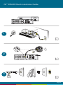
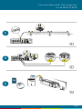
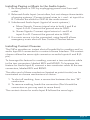
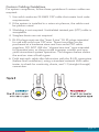
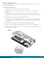
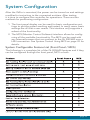
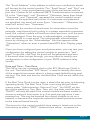
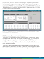
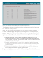
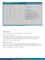
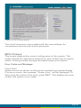
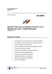
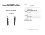
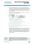
Qt 300/600
™
Installation & Operations Guide
csmqt.com
800.219.8199
Qt™ 300/600 Quick Installation Guide
1
2
3
page 2
For more information visit csmqt.com
or call 800.219.8199
4
5
6
page 3
Contents
Qt 300/600 Introduction
6
Hardware Installation
8
Installing the Control Module
8
Wall Mount
8
Rack Mount
9
Installing Qt Emitters
Emitter Installation Order
10
10
Installing Paging or Music to the Audio Inputs
12
Installing Contact Closures
12
Custom Cabling Guidelines
13
Battery Replacement
14
System Configuration (Front Panel and Monitor Control Software) 15
System Configurable Feature List (Front Panel / MCS)
15
Configuring the Control Module for the Network
16
IP Address DHCP
16
NETBIOS Support
16
Other Recommended Connections
16
Suggestions for Managing Multiple Control Modules
16
Front Panel Control
17
System Information
17
Setting Sound Masking Levels
18
Setting Audio Input Levels
20
Lock/Unlock the Front Panel
20
Configure Network Name and IP Address
21
Real-Time Clock or Network Clock
21
Reset System to Default Settings
21
System Control Using Monitor Control Software (MCS)
22
Connecting to the Qt 300/600 over Ethernet
22
MCS: Operation Section
23
page 4
Changing Masking Level Using MCS
24
Auto Ramping
24
Changing Input A and B Level
25
Time of Day Masking
26
Errors
27
27
MCS: Administration Section
Service
28
Zone Names
28
Networking and Security
28
Notification of Errors
28
Date and Time – Time Zone
29
Setting Equalizers and Emitter Fault Detection
MCS: Help
30/31
33
Links to Help Topics
33
Software Update
33
Documentation
34
34
MCS: Printout
Error Codes and Message
34
Post Installation Handoff
36
Warranty
37
Warranty
38
Settings Record
39
Homerun Zone Destination Record
40
page 5
Qt 300/600 Introduction
This manual discusses the installation of a sound masking system
using either the Qt 300 or the Qt 600. The Qt 300 and Qt 600
controllers have identical functionality, but different number of
zones supported - the Qt 300 supports 3 zones whereas the Qt 600
supports 6 zones. As you use this guide, remember the number of
zones and total area of coverage is the only real functional difference
between the systems. Collectively, the systems are referred to as
‘QtPro’ throughout this guide.
The Qt 600 supports six zones of sound masking, each with 1 to 120
emitters covering 100 to 12,000 square feet (9.3 m2 - 1,115 m2) per
zone. The Qt 300 supports three zones of sound masking, each with
1 to 120 emitters, covering up to 12,000 square feet per zone (1,115
m2). Each systems comes with two audio inputs which can be used
for paging and/or music. Additional controls for each zone include
time-of-day masking, auto ramping, self-monitoring fault detection
and notification, and independent equalizers for masking and audio
inputs. The system may be operated from its control module front
panel OR by a computer directly-connected to the module OR by
a computer connected through a local area network. See system
configuration on page 15.
It is important that the control module’s masking volumes be set
correctly for each zone to obtain the full effectiveness of the system.
If volumes are set too low, speech privacy will be reduced and work
place distractions will be much more apparent. If volumes are set too
high, the masking sound itself could become a source of distraction.
The higher the setting that can be used comfortably, the better the
acoustic privacy. For a given open office design, including ceiling
height, ceiling material and workstation panel height, we can define
the masking volume required to achieve “normal acoustic privacy,”
i.e., when it is relatively easy to ignore surrounding conversations.
For a very large range of open office designs, the target level is
in the 45–48 dBA range, measured 3 ft. (0.9 m) above floor level.
Similarly, for private offices, based on wall panel design and ceiling
construction, we can define masking volumes required to achieve
“confidential privacy,” i.e., conversations in adjacent offices cannot
be understood. Most private offices have a target level in the 38–42
dBA range, averaged spatially within the office.
page 6
Setting the masking volumes can be approached in one of two ways:
BEST: If a sound level meter is available, it is recommended that
the control module’s masking volumes be adjusted up or down to
achieve the following readings on the meter:
Private Office Zones
38-42 dBA, averaged spatially within the office
Open Area Zones
45-48 dBA, measured 3 ft. (0.9 m) above floor level
OTHERWISE: If a sound level meter is not available, the above levels
are likely to be achieved in most environments by setting the control
module’s masking volumes as follows:
Private Office Zones
05-09, for all ceiling heights
Open Area Zones
13-16, for 8 ft. (2.4 m) ceilings
15-18, for 10 ft. (3 m) ceilings
17-20, for 12 ft. (3.7 m) ceilings
Masking volumes must be set sufficiently high to improve speech
privacy and reduce distraction but not so high that the masking
sound becomes objectionable. Settings within the above ranges
should accommodate both objectives. As a general rule, use the high
end of the range. Base final settings on site conditions and customer
preferences. If people object to the sound level, set masking volumes
toward the bottom of the range or refer to the ‘Ramping’ section of
this guide, found on page 24 for more information on introducing
masking into the space gradually. Remember that the effectiveness
of the system relies on sufficient masking sound level and that initial
objections are often overcome as people become accustomed to the
sound.
Different day and a night volumes may be set. The control module
ramps linearly between these two settings beginning at the time
specified and over the period of time specified. As the control
module ramps between settings, the current volume is displayed
under “Current.”
NOTE: This document uses the QtPro software version 6.0.0 for
feature configuration.
page 7
Qt 300/600 Introduction
Installing the Control Module
NOTE: Always plug/unplug power supply at wall outlet
NOTE: The Qt 600 is shown in the figures, but the Qt 300 installs in
the same manner.
Wall Mount
Mount the bracket using the three screws and plastic anchors
(mollies) provided. Use a ¼ inch drill bit for the anchor hole. See
Figure 1.
Plastic anchors are #10-12 x 1¼ in. with #10 x 1½ screws.
B
A
Figure 1
GND
-/L
R
M3v
Bgnd
Check to see that the panel lock switch is in the
UN-LOCKED position.
Mgnd
B3v
A
AUDIO
B
+
NOTE: The control module hinges forward for wall mounting and
cable installation. To hinge forward, loosen screws A and B (see
Figure 1) used to secure the module during shipping.
page 8
Rack Mount
Attach optional rack mount brackets to each end of the control
module.
NOTE: When rack mounted, the control module does not hinge
forward.
A
Step 1
Remove the QtPro and
power supply bracket from
wall mount bracket.
B
Step 2
Reassemble power supply
to right rack mount bracket
using 6:32 black screws
(included with bracket).
Step 3
Fasten left and right rack
mount brackets to QtPro
using the screws removed in
Step 1.
B
Step 4
Mount QtPro to 19” cabinet
rail using 10:32 screws
as shown (included with
bracket).
page 9
Installing the Qt Emitters
Important Considerations:
▪▪ Each run has a maximum of 60 emitters
▪▪ Each run should have a maximum length of 1000 ft. (305 m).
▪▪ Each home run cable attached to the control module should
be labeled by zone # and run #. Adding a logical name (e.g.
Marketing, Private Offices) is suggested. In addition, fill out
“Home Run Zone Destination Record” at the end of this Guide.
▪▪ Each zone has two identical outputs, run 1 and run 2. All
emitters on run 1 and run 2 are controlled equally for each zone.
▪▪ Each job-made cable should be manufactured according to
ANSI/ TIA/EIA Standard 568-B. See custom cabling guidelines
on page 13.
▪▪ Job-made cables should be tested with a LAN tester before
installation. Adjustable emitters should be set for lower sound
levels, within a zone, when sound level measurements show an
acoustically loud subsection.
Emitter Installation Order
1. Set the masking output level of all zones to level 20.
2. Refer to the emitter layout and wiring diagram provided by the
dealer for cable run connections by zone.
3. Run home run cables from control module to the location of the
first emitter for all runs in all zones.
4. Gather all ceiling tiles (per layout drawing) that are to receive
emitters. Use the supplied hole saw to cut holes in designated
tiles. Cut all tiles from the front. (Different types of emitter
housings are available to attach in areas where there are no
suspended ceiling tiles.)
5. Push the emitter through the front of the hole in tile and secure
it by pushing down and twisting the locking ring at the back of
the emitter.
6. Connect a run cable from the specified zone OUTPUT jack on
the module to the INPUT jack of the first emitter. Listen to each
emitter as it is connected. If you cannot hear its “whooshing”
sound:
a. Try a different emitter.
b. Test all four previous cables for continuity and shorts.
Repair any faulty cables.
c. If there is a short, masking volume will shut off. The
short should clear itself in approximately five minutes.
If it does not, power cycle (unplug and re-plug) the
control module.
page 10
NOTE: The “tombstone” hook on the back of each emitter is next to
the INPUT jack. This can help you find the INPUT jack by touch.
NOTE: To adjust for unexpected obstacles such as sprinkler heads,
each emitter may be moved up to two feet (one tile) in any direction,
if necessary.
7. Connect the next OUTPUT cable to the emitter OUTPUT jack.
8. Run the cable to next designated tile specified on emitter layout
and wiring diagram. Tie cables up to structure or suspend from
deck as required by local building code.
9. On the next emitter, connect this cable to the INPUT jack.
10. Repeat Steps 4 through 9 for the remaining emitters on the
home run.
11. Set sound masking volume levels for each zone, using either the
front panel controls or the software interface. Set sound levels
according to Table 1.
12. If a small area within a zone exhibits a perceived volume louder
than the rest of the zone, use the adjustable emitter toggle
switches to turn the volume down for the emitters in that area.
Emitters can decrease volume by 3,6 or 9 dB. See emitter spec
sheet for more details.
Be sure to fix any problems and hear the “whooshing” sound before
installing the next emitter. If necessary see the Errors section of this
guide, found on page 27.
Note:
The input jack of each emitter bears this symbol
and is located near the safety tie off
The output jack of each emitter bears this symbol
page 11
Installing Paging or Music to the Audio Inputs
1. Be sure power is OFF by unplugging power cord from wall
outlet.
2. Balanced Audio Input: (most often, but not always characteristic
of paging systems.) Connect signal wires to + and - at input A or
B. Connect the shield to GND at the audio source.
3. Unbalanced Audio Input: (typical of music systems.)
a. Mono Signals: Connect signal wire to both L and R at
input A or B. Connect the ground wire to GND.
b. Stereo Signals: Connect signal wires to L and R at
input A or B. Connect the ground wire to GND.
4. If a music source is to be connected, using Input B allows
emergency music shut-off. See Contact Closures below.
Installing Contact Closures
The QtPro provides an instant shut-off capability for masking and/ or
audio Input B if connected to a contact closure interface. The contact
closure utilizes the same style connector as audio Inputs A and B (4pin).
To leverage this feature for masking, connect a two-conductor cable
to the two connectors, labeled M3V and MGND. To leverage this
feature for Audio Input B, connect a two-conductor cable to the two
connectors, labeled B3V and BGND.
The other end of these conductors (treated as pairs/circuits) can be
terminated on closure mechanisms of choice.
1. To shut off masking, form a connection between the two “M”
conductors.
2. To resume masking, break the connection (Don’t break the
connectors as you may want to reuse them).
The contact closure for audio Input B follows the same logic.
page 12
Custom Cabling Guidelines
For system compliance, follow these guidelines if custom cables are
required:
1. Use solid conductor 24 AWG CAT cable that meets local code
requirements.
2. If the system is installed in a return air plenum, the cable must
be plenum rated.
3. Shielding is not required. Unshielded twisted pair (UTP) cable is
acceptable.
4. Snagless boots are not required.
5. RJ-45 plugs must use the “bent 3-tine” RJ 45 plugs intended
for use with solid core CAT wire. Three tine plugs can be
purchased at a hardware store and from most CAT cable
suppliers. DO NOT USE the “aligned two-tine” type intended
for stranded wire, as they provide improper contact and may
yield intermittent system operation. The diagram below shows
the end-on view of both types.
6. Field test each cable after fabrication with the RJ-45 connectors
(before final installation), using a standard network LAN cable
tester, to check for continuity, shorts, and 1:1 (straight through)
connection.
page 13
Battery Replacement
A coin-style battery (Cr1220 or Br1220) powers the real time clock
during a power loss.
To replace the battery:
1. Unplug the control module from wall outlet.
2. Hinge the control module forward to access the connection
panel.
3. Remove the zone run connections. They should already be
labeled, if not, label before removing (for example: Zone 1 Run
2).
4. Remove the six screws that hold the panel.
5. Taking care not to disturb the other connections, lift the panel
to expose the coin battery in its housing at the front left of the
module.
6. Use a ball-point pen to dislodge the existing battery.
7. Insert a new battery with the positive (+) side facing upward.
8. Replace the connection panel, securing all six screws. Reconnect
the zone run cables.
page 14
System Configuration
After the QtPro is mounted, the power can be turned on and settings
modified to test wiring to the connected emitters. After testing,
it is time to configure the controller for operations. There are two
methods for performing configuration:
1. The front panel display can be used for basic configuration settings to get the system working and tested. In many cases, basic
settings are all that a user needs. This interface only supports a
subset of the functionality.
2. The MCS (Monitor Control Software) interface allows for configuring all the available functionality. The MCS can be used with
any internet browser that can connect to the Qt 300/600 over a
LAN connection. See System Control Using MCS on page 22 for
details.
System Configurable Feature List (Front Panel / MCS)
The following is a complete list of the Qt 300/600 features and if they
can be configured through the front panel, MCS or both.
page 15
Configuring the Control Module for the Network
IP Address DHCP
The IP address is preset for systems that are not on the network. To
directly connect to the control module over Ethernet, the user uses
any internet browser and places the IP address or control module
name in the navigation bar.
If the MCS is not used, DHCP will allocate an IP address when the
system is connected to the network. This field can be statically set
through the MCS, but it will be dynamically allocated when MCS is
not used.
NETBIOS Support
The system supports NETBIOS and advertises its hostname as QtXX,
where XX is the last two digits of the MAC address. The hostname
may be changed after a connection is made by a browser.
It may be helpful to use hostnames that convey information about
the area served, for example: qt_b1f3 (building one floor three). If
multiple control modules are installed on a single network, be sure
that no two control modules use the same hostname.
Other Recommended Connections
Access to an SMTP server enables the sending of error notification
emails.
Access to an SNTP server obtains the SNTP time stamp. The module
sends its SNTP request to “pool.ntp.org” (by default). If the SNTP
server is enabled, the real-time clock feature is disabled. A time
server other than the default time server may be specified in the
Administration section under date and time.
Suggestions for Managing Multiple Control Modules
Browser bookmarks are a convenient tool for managing multiple
control modules. A bookmark add-on stores bookmarks on a web
server and allows access from any computer on the LAN.
Create a “Sound Masking” folder (under Bookmarks) to hold a
bookmark for each control module. Use location-based names for
each module’s bookmark. To access a specific control module, open
Bookmarks>SoundMasking, and the specific module bookmark.
page 16
Front Panel Control
The front panel is used for configuring basic functionality and initial
system test. For advanced system configuration, the MCS is required.
Once the MCS is used to configure the system, using the front panel
will erase the settings configured by the MCS. Once the MCS is used
to configure the system, it should be used exclusively.
System Information
Initial displays of the front panel, shown below, shows the software
version and system status.
The VERSION X.X.X field stands for:
major release . minor changes . bug fixes.
The HxBx field is to identify the version of the internal code and used
as reference for technical support on rare occasions.
VERSION X.X.X
Status: OK HxBx
Status indicates if there are errors (see error codes, page 35) or if
the system is OK. The HxBx field indicates the version of the internal
code images and is only used by Cambridge Sound Management
when debugging a problem.
The MAC address is displayed for reference when the system is
on the network. The network administrator will need this when
configuring a network connection. This is also used when requesting
an advanced password for the MCS user interface.
Shown in the next block is the display for the IP Address. This is a
default value that can be used in a browser, for direct connection. As
noted, DHCP will change it when the system is on a network
IP Address DHCP
169.254.1.1
page 17
Hostname is set at the factory to a default value. This can be changed
through the MCS.
Host Name
QT XX
The next 2 blocks show the username and password when connecting
using MCS. The default is admin/secret. These can be changed at the
MCS window.
Username
admin
Password
secret
A warning message is displayed on the front panel after the MCS
is used for configuration (Warning: Time of day Ops). This tells
anyone about to use the front panel that the MCS has been used for
configuration and using the front panel will reset the settings made
by the MCS.
Setting Sound Masking Levels
Masking
Z1 Volume: Mute
Figure 10: The format of the panel for configuring masking. Z1 stands for zone 1
and it is currently set to mute.
There is a discussion in the Introduction section for recommended
volume settings.
Settings within the recommended ranges should optimize speech
privacy without excessive distractions. Generally, set masking volumes
toward the high end of the range and adjust according to site
conditions and user preferences. If possible, measure the results with
a sound level meter and check for the achieved sound pressure level.
Adjust as necessary or judge by listening in the area.
page 18
If installation occurs before the office is occupied, turn the system to
the desired level and leave it at that level. If the system is installed
after the office is occupied, turn the system to the correct level when
the space is unoccupied and employ auto ramping, only supported
through the MCS, to provide for a period of acclimatization.
To set the masking level for a zone, use the arrow keys on the front
panel to move to the right until the zone of interest is shown (Z1 is
zone 1 which matches the first column of ports on the back). Then use
the up and down arrows to change the value.
After setting the value for one zone, arrow to the right or left to
set the value for zone of interest. Repeat for all zones. If a portion
of a zone is louder than the rest of the zone due to a difference in
acoustics, it should either be a different zone of the volume lowered
using the adjustment on the back of the emitters. The volume will still
change based on the value of the controller, but the output can be
turned down 3,6 or 9 dB from the value set at the controller.
IMPORTANT:
For full system effectiveness, it is essential to set the volumes
correctly for each zone.
If the volume is set too low, speech privacy is reduced and workplace
distractions are more apparent.
If too high, the masking sound can become a distraction. Since,
in general, acoustic privacy improves as sound masking volume
increases, the general strategy is to set the masking volumes as high
as possible without being distracting.
NOTE: If making adjustments from the front panel, do not disconnect
power for 10 minutes after setting values, or data may be lost. If
adjustments are being made via the web interface, there is no need
to wait.
page 19
Setting Audio Input Levels
Input A
Z1 Volume: 6
This figure shows the format of the panel for configuring the volume for input A or
B. The level of the input is set for each zone, where the example shows Input A is
level 6 for zone 1.
The system has two inputs for paging or music. Either input may be
connected to any or all zones via software or front panel interface. If
no paging and/or music from these inputs are desired in a particular
zone, set the audio volume level of that zone to mute.
Note that Input B is the preferred music input due to its ability to be
shut down via a contact closure.
The audio input levels are set in a similar way as the masking. Use the
arrows on the front panel to move left and right to find the input A
and input B field for each zone. The inputs are enabled and level set
for each zone for flexibility. Arrow to each zone for each input and set
the level using the up and down arrows.
Lock/Unlock the Front Panel
The settings of the Qt 600/Qt 300 can be locked by a physical switch
on the back of the control module. Lock the control module panel by
moving the “lock” switch to the “Locked” position. This prevents any
casual interaction from changing the settings.
Unlock the Front Panel and Control the System
1. Loosen screws and lift the control module slightly and hinge it
forward to give access to its connection panel.
2. Move the panel lock switch to the UNLOCKED position. Close
the module.
3. Press NEXT or PREVIOUS to scroll between screens for adjusting
sound masking, paging or music volumes by zone.
4. Modify a value by 1 dB on any screen by pressing + or -.
5. Press NEXT to accept a screen value.
6. After completing adjustments, lock the system.
NOTE: The system returns to the Version, Status screen after five
minutes of inactivity. Z1 indicates Zone 1, Z2 indicates Zone 2, etc.
If an error is detected, an error code is displayed on the control
module. See page 35 for details about Error Codes.
page 20
Configure Network Name and IP Address
Creating a static IP address or controller name is not available from
the front panel. The MCS software can configure both the network
name and the IP address (see below). If the system is not connected
to the network, the initial values shown on the front panel are used
when connecting a PC to the QtPro over Ethernet.
If the QtPro is connected to the network, a DHCP server will
dynamically allocate an IP address. The system MAC address is used
by the network system administrator to configure the DHCP server.
NOTE: When connecting a PC directly to the control module, the
control module acts as a DHCP server and serves the DHCP enabled
PC and IP address.
Real-Time Clock or Network Clock
If the QtPro is not connected to the network, it will use a real-time
clock within the controller. This requires the battery for power. This is
often the way time is supplied to the QtPro.
If the QtPro is on the network, it will look for the network clock to
retrieve the time and date. Access to an SNTP server obtains the
SNTP time stamp. The module sends its SNTP request to “pool.ntp.
org” (by default). If the SNTP server is enabled, the real-time clock
feature is disabled. A time server other than the default time server
may be specified on the MCS.
NOTE: When the QtPro is configured in the factory the date and time
is set to Jan 1. Basic operations will work without changing this time.
For any advanced features that require the time of day, either the
network clock or correct setting of the time is required.
Reset System to Default Settings
To clear an error indication (after problem is fixed) or reset the
settings to the initial default state, the system should go through a
hard reboot.
Steps for the hard reboot:
1. Unplug the power and wait 15 seconds or more.
2. Hold the up arrow on the front panel and re-connect power.
Release the up arrow once the LCD display shows it is booting.
page 21
System Control Using Monitor Control Software (MCS)
The MCS (Monitor Control Software) is an interface that configures
the QtPro over a LAN/network connection. The MCS software is
operated from any network browser. Below are the instructions to
connect to the control module over Ethernet locally and over the
network.
After the discussion on connecting to the control module, the MCS
screens will be discussed.
Connecting to the Qt 300/600 over Ethernet
1. System software is operated from any network browser. Software
is pre-installed in the control module. The HELP function
provides comprehensive software control operating instructions.
2. Connect a computer or the network to the 10/100 Ethernet jack.
3. Power the control module on by plugging it into a standard wall
outlet.
4. Press the right arrow on the control module to advance to the IP
address screen. An assigned IP address is displayed on the front
panel within two minutes of powering the module.
5. Access the Qt System Monitoring and Control Software
a. Read the control module Hostname or IP address
from the front control panel.
b. Enter either the hostname or IP address into the
browser address bar.
c. A prompt will appear requiring a username and
password.
d. The default username is “admin”. The default
password is “secret”.
6. After logging in with the defaults, you may change the
hostname, username and password.
DHCP Support
The system uses DHCP to obtain an IP address.
The system displays its MAC address on the front panel. This allows
the network administrator to use the MAC address to configure
the DHCP server to deliver a fixed (static) IP address to the control
module.
page 22
MCS: Operation Screen
Figure 12: Operations Section in review mode.
Note: The software version is displayed at the bottom right of every screen. The 3
digits indicate major release version, minor feature changes and bug fixes. There
are times when Cambridge Sound Management will release software to fix unique
bugs or small feature changes, and later roll them in to a major release. When a
customer reports a problem, the software version number is usually requested. The
Qt 300 will only differ on this screen by the number of zones shown. The Qt 600 will
display six, while the Qt 300 will only display three.
Figure 13: Operations Section in modify mode
The Operations Section contains two blocks. The block on the left
allows the configuration of:
▪▪ Masking level for min and max outputs.
▪▪ Sound level for auxiliary audio inputs A and B.
▪▪ Auto ramping.
The block on the right allows for the configuration of:
▪▪ Ramping start times.
▪▪ Ramping interval.
▪▪ Weekend ramping schedule.
page 23
Changing Masking Level Using MCS
Follow these steps to update the parameters within the masking level
block:
1. Review – selecting the review button will allow the user to select
a zone and see the current configuration. Click on the zone on
the right side of the operations screen.
2. To modify a zone, start by clicking the modify button.
3. Select the zones to modify by checking the boxes of the zones
on the right side of the operations screen.
4. To set the masking level, use the multi-select for max. and min.
settings in the left box.
5. Select Submit to commit the values.
NOTE: Only modify one block at a time and then click submit. If
you modify both zone masking and Time of Day, only one window
is updated. The suggested volume setting is discussed earlier in the
Introduction section.
If a portion of a zone is louder than the rest of the zone due to a
difference in acoustics, it should either be a different zone of the
volume lowered using the adjustment on the back of the emitters.
The volume will still change based on the value of the controller, but
the output can be turned down 3,6 or 9 dB from the value set at the
controller.
Auto Ramping
The Auto Ramping function is typically used once, when the system
is first installed. The Auto Ramping function is used to introduce
sound masking into an occupied space gradually. The Auto Ramping
function sets the operational volumes for a zone a specified number of dBA below its programmed value. The control module will
raise the zone’s operational level by 1 dBA per weekday until the
Auto Ramping value is back to zero and the zone is operating at its
specified “Max” and “Min” values. If the system is running “quiet,”
check that Auto Ramping has been set properly. The Auto Ramping
control is also a useful means of temporarily lowering the volume in
a zone. This may be necessary if, for instance, there is a problem with
some other electrical or mechanical system and maintenance needs
absolute quiet to listen for the source. By using the Auto Ramping
control, if the administrator forgets to shut off auto-ramping, the
control module will gradually ramp back to the operational levels. If
the administrator had “Muted” the zone using the “Max” and “Min”
levels, masking would remain off indefinitely until someone set off to
correct the problem.
page 24
Example: Zone 1 is planned to be masking level 9. Auto Ramping
is set to -15dB. On day one, the level is active 15dB less than the
planned level. Day 2, it is only 14 dB lower. It rises each day until it is
functioning at full masking.
Changing Input A and B Level
The control module operates as a paging amplifier. Refer to the control module’s specifications for the electrical characteristics of Inputs
A and B. Each signal is routed to all zones. The (acoustical) output
level for each signal can be specify for each zone. Set a Zone/ Input
A/B output level to “Mute” if you do not wish to connect the signal
to the zone.
NOTE: Input B is the preferred music input due to its ability to be
shut down via a contact closure.
The audio input levels are set in a similar way as the masking. Within the Operations window, each zone has a selector for the level of
input A or B.
1. Select the modify button.
2. Select the zones to modify on the right by clicking the box.
3. Change the value in the left window.
4. Select Submit.
Auxiliary Line Level Adjustment
From the operations tab and the zone block (shown in figure 13), selecting the Input A or Input B link in the window will open the window
shown below. This allows the incoming level on the auxiliary input
to be left at line level or increased by 10 dB in the case that the line
level is below typical AV line level -10 dBv to +4 dBv.
page 25
Select Line Level to use the signal as it comes to the controller and
adjust volume from the zone window. Use Boost to add 10 dB to
the signal and then continue the adjustment of volume in the zone
window.
Time of Day Masking
QtPro allows the specification of a max time masking volume and
a min time masking volume for each zone. This allows complete
flexibility to when the masking level needs to be high or low. Use the
pull down menus to specify each start time and the ramping interval
- the period of time allotted to accomplish the full, linear (in 0.5 dB
increments) transition. QtPro also allows you to specify Saturday
and Sunday operation. You can chose weekday operation (max/min)
or min operation where the min volume is in effect for the entire
(weekend) day.
QtPro obtains the time-of-day from either an Internet-based NTP time
server (pool.ntp.org) using the SNTP protocol or from its onboard real
time clock. QtPro requires the user to define the time zone in which
the box is operating and the daylight savings time rules for that time
zone. If you are unfamiliar with your time zone, or daylight savings
time rules, a quick search on the Internet should help you find this
information. Go to “Administration: Time Zone” to specify the control
module’s time zone and daylight savings time rules.
NOTE: NTP timer servers do not provide time zone or daylight
savings time rules and therefore these values MUST be specified by
the administrator.
page 26
Errors
If the control module is operating properly, software will display
“Status: Ok”. If the control module encounters an error, software will
display “Status: Error”. Click on “Error” to obtain additional information. Click on “acknowledge” to clear the error (see Administration:
Notification of Errors, page 28). If the error condition persists, the
error will be signaled again after clearing the error.
WARNING: If a “System Thermal Fault” occurs, be sure that the
control module is not exposed to conditions beyond its ambient air
specification of 104°F, 40°C.
WARNING: In order to protect the electronic circuitry from damage,
the control module introduces a delay after experiencing an amp
short before turning the amp back on. A persistent short will result in
the amp being turned off once again. Shorts are most likely to occur
during installation of the system due to termination mistakes by the
installer. Shorts are unlikely once the control module is operational.
MCS: Administration Section
The following section will use figure 14 for reference.
Figure 14: Administration Section
IMPORTANT: Only update one block at a time and press Submit!
Changes to blocks that are not submitted will be lost if a different
block is submitted.
page 27
Service
The service window holds the following fields:
Control Module Name: This is just a reference name for the
control module and is not used for networking. An example of an
informative name is “120 Main Street - First Floor”.
Location: This is a good reference to track where the control
module is located when faults are detected. Faults can be sent
via email and the control module’s location can be useful.
Serviced By: This is for getting help when there are errors/ problems. The name of the service company can be stored. By default
it is Cambridge Sound Management, but it could be changed to
the installer.
Phone No.: Cambridge Sound Management (by default)
Zone Names
Use this screen to provide informative names for each served zone.
Examples of informative names are: “Reception”, “Offices East”,
“Cubicles East”, “Offices West”, and “Cubicles West”.
Networking and Security
Use this screen to obtain the control module’s MAC and IP Addresses,
to change its NETBIOS hostname, and to change the username
or password for logging in. If you change the control module’s
hostname, QtPro will automatically advertise its new NETBIOS name.
NOTE: If the control panel is locked (the toggle switch on the inside
of the control module is set to the “locked” position), the control
module cannot be controlled from its front panel. If it is unlocked, the
control module’s operational parameters can be modified from the
control panel.
NOTE: The “Username” and “Password” specified under
Administration: Networking and Security to control access to
the control module over the network, and the “Username” and
“Password” specified under “Administration: Notification of Errors”
to log into an SMTP outbound mail server need not be identical.
Notification of Errors
Use this screen to configure access to the mail server that will be
used by QtPro for sending email messages notifying the system
administrator of errors.
page 28
The “Email Address” is the address to which error notification emails
will be sent by the control module. The “Email Server” and “Port” are
the name (i.e., smtp.mymailservice.com) of the mail server and the
port that it listens to for outbound SMTP. If authentication is required,
fill in the “Username” and “Password.” Otherwise, leave them blank.
“Username” and “Password” represent the control module’s email
account on the specified mail server. If a username and password
are specified, the email will arrive From: “Username.” Otherwise, the
email will arrive From: “Hostname.”
To minimize the number of emails sent for intermittent errors (for
example, amp thermal fault cycling in a system exposed to excessive
heat), the control module will send one email per error, until the error
is acknowledged. Once the error is acknowledged, a subsequent
error will result in a new email. The administrator acknowledges
errors by clicking on the “Acknowledge” link that appears under
“Operations” when an error is present (see MCS Error Display, page
34).
Once you have configured your email parameters, you may test your
configuration by asking the control module to generate a “test”
email. To do this, click Test. An email will be generated and sent.
If the email does not get through, you may need to modify your
configuration or the configuration of your SMTP outbound relay
(server).
Date and Time – Time Zone
The QtPro can use a network clock or the RTC (Real-time Clock) in
the unit. The field called “NTP Server” is used to identify the name
of the network time server when it is being used (default being pool.
ntp.org). The date and time for the Real-time Clock are set within this
window.
If the Real Time Clock is to be used, it should be set prior to adjusting
operating levels. The Real Time Clock is set using the pull-down
menus under “Administration: Date and Time”. You MUST set the
day-of-the-week (e.g. Sun, Mon, Tues, etc), the date, and the time.
The RTC will only be used if the control module has been unable to
access an external time server (e.g. 0.us.pool.ntp.org) since it was
powered on. This may be because the control module is not on a
network or because the corporate network’s firewall prevents access
to the Internet based servers.
The source for the control module’s time stamp is listed next to the
time stamp as either “SNTP” (external time server - accessed via
page 29
the “Simple Network Time Protocol” protocol) or “RTC” (Real Time
Clock).
WARNING: Manually changing the RTC’s time/date via the
“Administration: Date and Time” window should not be attempted
between the hours of 12:00 AM and 2:00 AM on DST transition days
(two per year). Doing so could result in a missed “spring ahead” or
“fall behind” event. Set the date and time before midnight on a DST
transition day or after 2:00 AM on a DST transition day.
If the date is wrong following a power failure, and the system is
relying on the internal real time clock (RTC) and not a network-based
time server, it is likely that the RTC’s battery is depleted. Replace the
battery (see battery replacement, page 14). Reassemble the control
module and then plug it back into the wall outlet. Reset the Real
Time Clock.
Setting Equalizers and Emitter Fault Detection
A special login password is required to gain access to the ENFD
screens. Contact Cambridge Sound Management to obtain the
password(s) for your control module(s). You will need to provide
the Mac Address of each control module. See “Administration:
Networking and Security” for the MAC Address or it can be seen on
the front panel.
Below are the screens for emitter fault detection and equalizer
settings when logged in with the second level password.
Equalizer Update
After logging in with the second level password, the operations
sections will have a block that includes the equalizer settings. The
Masking and Audio equalizers are configured by the factory and
should not need to be modified in most installations. However,
if desired, the equalizers may be used to adjust the system to a
different masking, paging, or music spectrum.
You may specify the gain for a tap in its corresponding box. All values
are measured in dB and the range is +/- 12 dB, in whole number
increments. To specify a negative gain, precede the number by a
minus sign (for example, -2). Once you have specified all of the taps
of interest, press “Submit.” The values will be changed and saved,
and the equalizer will redraw to provide a visual representation of
your settings.
When an equalizer’s settings are modified, the control module
calculates and reports the impact the new settings have on speech
page 30
privacy. The report is shown in the Masking Equalizer control box
and is stated in terms of change to the Privacy Index. A change
must be at least 1% for it to display. The calculation is performed as
specified in “ASTM International; Designation: E1130-02, Standard
Test Method for Objective Measurement of Speech Privacy in Open
Offices Using Articulation Index”.
Figure 15: Operations Section with the equalizers block displayed after a higher
level password has been entered.
ENFD (Emitter Network Fault Detection)
The ENFD is a feature used after installation to monitor the status
of the emitter cable runs. As shown on the screen, the installation
should be complete without defect before the ENFD feature is
enabled. The installation is complete by following the steps for
installation, ensuring all the emitters are working and there are no
error codes displayed.
The ENFD feature will start taking measurements of the cable runs
after power is applied. It will take 15 minutes after booting to learn
the emitter network and determine the steady state of the system.
page 31
Figure 16: Standard view of the ENFD configuration section.
The diagram above shows the window as it appears and is learning
the network configuration.
After the 15 minutes are expired and the system is fully installed, it
is time to enable fault detection if you desire. It is not required for
proper operation. The window shown on the next page shows that
after the 15 minutes have expired there is a dropdown in the upper
right corner that allows 3 actions:
1. Refresh settings - this is used just before enabling ENFD to
make sure any setup data is cleared and proper measurements
will be taken. This can also be used after an error has been fixed
and a new test can begin.
2. Enable fault detection - once this is selected, select the zone
in which you want the emitter run monitored, by choosing the
submit button.
3. Disable fault detection - this is used to turn off the feature by
then using the submit button for each run
If there is a fault, an error code 4 will be displayed for that failed zone
in the status block.
page 32
Figure 17: ENFD adjustment drop-down view
MCS: Help
The following section will use figure 18 for reference.
Links to Help Topics
From the Help screen on the MCS, there are links to some common
questions when using the MCS. The links are shown on the right
under Operations and Administration. This information is also
contained within this document.
Software Update
This is a link to the Cambridge Sound Management web site for
access to the latest software. When the user selects the link from the
MCS, it displays the current software on the control module and the
version of software available to install.
page 33
Figure 18: MCS Help Section
The install directions are provided with the new software for
convenience and not part of this document.
MCS: Printout
This screen displays the current configuration of the system. This
screen should be captured and stored in case of data loss or system
failure. Printing is done through the web browser print option.
Error Codes and Messages
Front Panel
System errors are shown on the control module front panel display.
If an error occurs, the message “Status: Error” will be displayed. To
determine the cause of the error, press NEXT. This displays the error
screen with system error codes.
page 34
Error Codes
If one or more errors exist in the sound masking system, an eight
digit error code is displayed on the LCD display (scroll forward to the
“Error” screen). The error state is indicated by an eight digit code of
the form:
Error: 0_000000
Error Code for Zone 1
Error Code for Zone 2
Error Code for Zone 3
Error Code for Zone 4
Error Code for Zone 5
Error Code for Zone 6
Reserved
Error Code for Control Module
Where a number other than “0” indicates an error.
Examples
Error: 00000100
Short sensed in the wiring in zone 3
Error: 00110000
Short sensed in the wiring in zones 5 and 6
Error: 00000004
One or more emitters are not operating in zone 1
Error: 80000000
Contact the manufacturer
MCS Error Display
When there is an error in the system, the operations window will show
a status in red as shown in the window below. Beside the status are
the words “Error” and “acknowledge” which are described next.
page 35
Selecting “Error” for the screen above pops open a window that
details the error in the system. The format of the error string is the
same as shown on the front panel. The screen below shows there
are emitter faults in 3 zones and the administrator should look for
nonfunctional emitters.
Click OK to close the window.
Click the acknowledge link and the status goes back to OK. If the
error persists, the status will show the error. This can be used to test
problem resolutions.
Post Installation Handoff
Perform a final walkthrough to satisfy all aspects of the system
performance:
1. Fill out the settings record.
2. Store guide with completed settings record in the clear plastic
job ticket holder next to the control module. If there is a hard
module failure, the recorded values can be used to reconfigure
the system. System settings are retained after a power outage.
3. Lock the control module panel by moving the “lock” switch to
the Locked position.
4. Lift the control module front panel and hinge it backward into its
closed position. Tighten all retaining screws.
5. If operating by software control, show the administrator how to
connect to the control module using both the Hostname and IP
Address methods. Share this guide with the administrator.
page 36
WARRANTY:
Note: This equipment has been tested and found to comply with the limits for
a Class A digital device, pursuant to part 15 of the FCC Rules. These limits are
designed to provide reasonable protection against harmful interference when
the equipment is operated in a commercial environment. This equipment
generates, uses, and can radiate radio frequency energy and, if not installed
and used in accordance with the instruction manual, may cause harmful
interference to radio communications. Operation of this equipment in a
residential area is likely to cause harmful interference in which case the user
will be required to correct the interference at his own expense.
Modifications not expressly approved by the manufacturer could void the
user’s authority to operated the equipment under FCC rules.
Warranty Coverage — Qt™ Emitters
Cambridge Sound Management, LLC (the “warrantor”) will, for a period of five
(5) years, starting with the date of purchase, warrant that the Qt™ Emitters
(the “speakers”) will be free of defects in materials and workmanship that
interfere with proper operation as a sound masking, paging and music speaker
system. During that period, the warrantor will, at its option, either (a) repair the
speaker, or (b) replace the speaker. The decision to repair or replace will be
made by the warrantor.
Warranty Coverage — Qt control unit
The warrantor will, for a period of one (1) year, starting with the date of
purchase, warrant that the Qt control unit (the “system”) will be free of defects
in materials and workmanship that interfere with its proper operation as a
sound masking, paging and music distribution control system. During that
period, the warrantor will, at its option, either (a) repair the system, with new or
refurbished parts, or (b) replace the system with a new or refurbished system of
equal functionality at no charge. The decision to repair or replace will be made
by the warrantor.
All software installed in the Qt system is warranted to substantially conform to
its published specifications. In no event does the warrantor warrant that the
software is error free or that the customer will be able to operate the software
without problems or interruptions. The warrantor will, from time to time,
make available software bug fixes. It is the responsibility of the purchaser to
download and install these software modifications.
Except for the forgoing, all software and software upgrades are
provided AS IS.
The following terms apply to all
These warranty terms are extended only to the original purchaser of a new product.
A purchase order or other proof of the original purchase date and purchaser is
required for warranty service.
page 37
Obtaining warranty repairs: Please access and review online help
resources for the product before requesting warranty service. If the product
is still not functioning properly after making use of these resources, please
contact Cambridge Sound Management for a return authorization number. All
returns are to be prepaid. The warrantor will pay return surface freight within
the continental United States on warranty repairs. All customs and freight
charges in excess of surface freight within the United States will be born by the
purchaser.
Warranty Limits and Exclusions
This warranty ONLY COVERS failures due to defects in materials or
workmanship, and DOES NOT COVER normal wear and tear or cosmetic
damage. THIS WARRANTY DOES NOT COVER USE OF THE SYSTEM WITH
ANY OTHER SPEAKER OR EMITTER MANUFACTURED BY ANY ENTITY,
ORGANIZATION OR COMPANY OTHER THAN CAMBRIDGE SOUND
MANAGEMENT, LLC OR USE OF THE SYSTEM FOR ANY PURPOSE OTHER
THAN SOUND MASKING AND/OR PAGING AND/OR MUSIC DISTRIBUTION.
THIS WARRANTY DOES NOT COVER THE USE OF ANYTHING OTHER THAN
CAT-3 OR EQUIVALENT, 24 GAGE CABLING. The warranty ALSO DOES
NOT COVER damages that occurred in shipment, failures that are caused by
products not supplied by the warrantor (e.g., replacement power supplies)
or failures that result from accidents, misuse, abuse, neglect, mishandling,
misapplication, alteration of any sort, installation, use as a system driver during
speaker installation, set-up adjustments, misadjustment of controls, improper
maintenance, power line surge, lightning damage, power surges, modification,
rental use, service by anyone other than the warrantor or damage that is
attributable to acts of God.
THERE ARE NO EXPRESS OR IMPLIED WARRANTIES EXCEPT AS LISTED
UNDER “WARRANTY COVERAGE.” THE WARRANTOR IS NOT LIABLE FOR
ANY INCIDENTAL OR CONSEQUENTIAL DAMAGES RESULTING FROM
THE USE OF THE PRODUCT OR ARISING OUT OF ANY BREACH OF THIS
WARRANTY. As an example, this specifically excludes damages for lost
time, lost use of the system, cost of removal or reinstallation of the system
or travel to and from the purchaser’s location. ALL EXPRESS AND IMPLIED
WARRANTIES ARE LIMITED TO THE PERIOD OF THE WARRANTY.
This warranty provides specific legal rights, and there may be others that
vary from state to state or in the country of compliant use. Therefore, certain
additional exclusions may apply.
page 38
Settings Record (Installer/Administrator)
If using software control, select the “Print Settings” link under the Administration page to print a complete list of system information. Place
the printout in the job ticket holder near the control module. If using
front panel control, fill in the details below. This information is critical
to ease recovery from a hardware fault.
page 39
Homerun Zone Destination Record
Zone 1
Run 1 ____________
Run 2 ____________
Zone 2
Run 1 ____________
Run 2 ____________
Zone 3
Run 1 ____________
Run 2 ____________
Zone 4
Run 1 ____________
Run 2 ____________
Zone 5
Run 1 ____________
Run 2 ____________
Zone 6
Run 1 ____________
Run 2 ____________
csmqt.com
800.219.8199