1
MB760 / MB770
MPS5502
Service Manual
70913A
Copyright © 2013 by Oki Data. All Rights Reserved
Oki Data America's, Inc. ("Oki Data"), authorizes you to view, copy, and print
documents published by Oki Data for noncommercial use within your organization only.
In consideration of this authorization, you agree and acknowledge that any copy of these
documents shall retain all copyright and proprietary rights contained herein. Each
document published by Oki Data may contain additional copyright information and
proprietary notification relating to that individual document.
Nothing contained herein shall be construed as conferring by estoppel, implication or
otherwise any license or right under any patent or trademark of Oki Data, Oki Electric
Industry Co., Ltd. ("Oki Electric"), or any third party. Except as provided above nothing
contained herein shall be construed as conferring any license or right under any Oki
Data copyright.
Oki Data has taken care to insure that the information which follows is complete,
accurate and up-to-date. However, Oki Data assumes no responsibility for errors or
omissions which may occur. All the information provided is subject to change from time
to time at the sole discretion of Oki Data.
All publications may include technical inaccuracies or typographical errors. We reserve
the right to make periodic changes, additions, and deletions to publications without
notice.
The most up-to-date drivers and manuals are available from the web site:
http://www.okiprintingsolutions.com
Oki Data CONFIDENTIAL
Oki Data CONFIDENTIAL
Trademarks
• The official name of Windows 8 is Microsoft Windows 8 Operating System.
• The official name of Windows 7 is Microsoft Windows 7 Operating System.
• The official name of Windows Vista is Microsoft Windows Vista Operating System.
• The official name of Windows XP is Microsoft Windows XP Operating System.
• Microsoft, Windows, Windows NT, Windows Vista and the brand names and product names of
other Microsoft products are trademarks or registered trademarks of Microsoft Corporation in
the U.S. and/or other countries.
• Apple, AppleTalk, Macintosh, and Mac are trademarks of Apple Inc. in the U.S. and other
countries.
• PostScript is a trademark of Adobe Systems Incorporated.
• NOVELL, NetWare, and NDS are trademarks or registered trademarks of Novell, Inc.
• FLOIL is a registered trademark of Kanto Kasei Ltd. CORPORATION.
• Molykote is a registered trademark of Dow Corning Corporation.
• Web Page is a trademark of OKI DATA Corporation.
• Other company names and product names in this manual are the trademarks of their
respective companies.
© 2013 OKI DATA CORPORATION All rights reserved
Under the copyright laws, this manual cannot be reproduced in any form without prior written
permission of OKI DATA CORPORATION.
45641001TH Rev.1
iii /
Oki Data CONFIDENTIAL
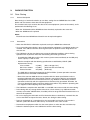
GENERAL PRECAUTIONS REGARDING THE SERVICE FOR THIS EQUIPMENT
The installation and service shall be done by a qualified service technician.
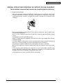
1. Transportation/Installation
- When transporting/installing the equipment, employ two or more persons and be sure
to hold the positions as shown in the figure. The equipment is quite heavy and weighs
approximately 55 kg (121.23 lb.) (including the finisher), therefore pay full attention when
handling it.
- Be sure not to hold the movable parts or units (e.g. the control panel, ADU or RADF) when
transporting the equipment.
- Be sure to use a dedicated outlet with AC 110V/15A, 120V/12A, 220-240V/8A for its power
source.
- The equipment must be grounded for safety.
- Select a suitable place for installation. Avoid excessive heat, high humidity, dust, vibration
and direct sunlight.
- To insure adequate working space for the copying operation, keep a minimum clearance of
30 cm (12”) on the left, 30 cm (12”) on the right and 60 cm (24”) on the rear.
- The equipment shall be installed near the socket outlet and shall be accessible.
- Be sure to fix and plug in the power cable securely after the installation so that no one trips
over it.
- If the unpacking place and where the equipment is to be installed differ, perform image
quality adjustment (automatic gamma adjustment) according to the temperature and
humidity of the place of installation and the paper to be used.
- If the equipment has casters, lock them after the installation.
45641001TH Rev.1
iv /
Oki Data CONFIDENTIAL
2. General Precautions at Service
- Be sure to turn the power OFF and unplug the power cable during service (except for the
service should be done with the power turned ON).
- Unplug the power cable and clean the area around the prongs of the plug and socket outlet
once a year or more. A fire may occur when dust lies on this area.
- When the parts are disassembled, reassembly is the reverse of disassembly unless
otherwise noted in this manual or other related documents. Be careful not to install small
parts such as screws, washers, pins, E-rings, star washers, harnesses in the wrong places.
- Basically, the equipment should not be operated with any parts removed or disassembled.
- The PC board must be stored in an anti-electrostatic bag and handled carefully using a
antistatic wrist strap since the ICs on it may be damaged due to static electricity.
Caution: Before using the antistatic wrist strap, unplug the power cable of the equipment
and make sure that there are no charged objects which are not insulated in the
vicinity.
- Be sure not to touch high-temperature sections such as the fuser unit and areas around
them.
- Be sure not to touch high-voltage sections such as the chargers, transfer belt, developer,
high- voltage transformer, and power supply unit. Especially, the board of these
components should not be touched since the electric charge may remain in the capacitors,
etc. on them even after the power is turned OFF.
- Make sure that the equipment will not operate before touching potentially dangerous places
(e.g. rotating/operating sections such as gears, belts pulleys, and fans).
- Be careful when removing the covers since there might be the parts with very sharp edges
underneath.
- When servicing the equipment with the power turned ON, be sure not to touch live sections
and rotating/operating sections.
- Use designated jigs and tools.
- Use recommended measuring instruments or equivalents.
- Return the equipment to the original state and check the operation when the service is
finished.
- Be very careful to treat the touch panel gently and never hit it. Breaking the surface could
cause malfunctions.
3. Important Service Parts for Safety
- The door switch, fuse, thermostat, thermofuse, thermistor, batteries, IC-RAMs including
lithium batteries, etc. are particularly important for safety. Be sure to handle/install them
properly. If these parts are short-circuited and their functions become ineffective, they may
result in fatal accidents such as a burnout. Avoid short-circuiting and do not use parts not
recommended by OKI DATA Corporation.
45641001TH Rev.1
v/
Oki Data CONFIDENTIAL
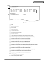
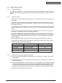
4. Cautionary Labels
- During servicing, be sure to check the rating plate and cautionary labels to see if there is
any dirt on their surface and if they are properly stuck to the equipment.
[1]
[1] Identification label
5. Disposal of the Equipment, Supplies, Packing Materials, Used Batteries and IC-RAMs
- Regarding the recovery and disposal of the equipment, supplies, packing materials, used
batteries and IC-RAMs including lithium batteries, follow the relevant local regulations or
rules.
- Never attempt to incinerate a used transfer belt unit. This could cause an explosion and
burn you since the toner inside would be scattered.
Caution:
Dispose of used batteries and IC-RAMs including lithium batteries according to this
manual.
Attention:
Se débarrasser de batteries et IC-RAMs usés y compris les batteries en lithium selon ce
manuel.
Vorsicht:
Entsorgung der gebrauchten Batterien und IC-RAMs (inclusive der Lithium-Batterie) nach
diesem Handbuch.
45641001TH Rev.1
vi /
Oki Data CONFIDENTIAL
ALLEGEMEINE SICHERHEITSMASSNAHMEN IN BEZUG AUF DIE WARTUNG
Die Installation und die Wartung sind von einem qualifizierten ServiceTechniker durchzuführen.
1. Transport/Installation
- Das Tragen oder Installieren des Gerätes braucht wenigstens zwei Menschen. Die
angezeigten Stellen sind wie in der Abbildung festzuhalten. Das Gerät ist ziemlich schwer
und wiegt ungefähr 55 kg (mit dem Finisher); deshalb wenn Sie es hochheben oder tragen,
passen Sie besonders auf.
- Beim Transportieren des Geräts nicht an den beweglichen Teilen oder Einheiten (z.B. das
Bedienungsfeld, die Duplexeinheit oder die automatische Dokumentenzuführung) halten.
- Eine spezielle Steckdose mit Stromversorgung von AC 110V/15A, 120V/12A, 220-240V/8A
als Stromquelle verwenden.
- Das Gerät ist aus Sicherheitsgründen zu erden.
- Einen geeigneten Standort für die Installation wählen. Standorte mit zuviel Hitze, hoher
Luftfeuchtigkeit, Staub, Vibrieren und direkter Sonneneinstrahlung sind zu vermeiden.
- Um einen optimalen Kopierbetrieb zu gewährleisten, muss ein Abstand von mindestens 30
cm links, 30 cm rechts und 60 cm dahinter eingehalten werden.
- Das Gerät ist in der Nähe der Steckdose zu installieren; diese muss leicht zu erreichen
sein.
- Nach der Installation muss das Netzkabel richtig hineingesteckt und befestigt werden,
damit niemand darüber stolpern kann.
- Falls der Auspackungsstandort und der Installationsstandort des Geräts verschieden
sind, die Bildqualitätsjustierung (automatische Gammajustierung) je nach der Temperatur
und Luftfeuchtigkeit des Installationsstandorts und der Papiersorte, die verwendet wird,
durchführen.
- Wenn das Gerät Rollen hat, sind sie nach der Installation zu verriegeln.
45641001TH Rev.1
vii /
Oki Data CONFIDENTIAL
2. Allgemeine Sicherheitsmassnahmen in bezug auf die Wartung
- Während der Wartung das Gerät ausschalten und das Netzkabel herausziehen (ausser
Wartung, die bei einem eingeschalteten Gerät, durchgeführt werden muss).
- Das Netzkabel herausziehen und den Bereich um die Steckerpole und die Steckdose die
Umgebung in der Nähe von den Steckerzacken und der Steckdose wenigstens einmal
im Jahr reinigen. Wenn Staub sich in dieser Gegend ansammelt, kann dies ein Feuer
verursachen.
- Wenn die Teile auseinandergenommen werden, wenn nicht anders in diesem Handbuch
usw erklärt, ist das Zusammenbauen in umgekehrter Reihenfolge durchzuführen.
Aufpassen, dass kleine Teile wie Schrauben, Dichtungsringe, Bolzen, E-Ringe, SternDichtungsringe, Kabelbäume nicht an den verkehrten Stellen eingebaut werden.
- Grundsätzlich darf das Gerät mit enfernten oder auseinandergenommenen Teilen nicht in
Betrieb genommen werden.
- Das PC-Board muss in einer Anti-elektrostatischen Hülle gelagert werden. Nur Mit einer
Manschette bei Betätigung eines Armbandes anfassen, sonst könnte es sein, dass die
integrierten Schaltkreise durch statische Elektrizität beschädigt werden.
Vorsicht:Vor Benutzung der Manschette der Betätigung des Armbandes, das Netzkabel
des Gerätes herausziehen und prüfen, dass es in der Nähe keine geladenen
Gegenstände, die nicht isoliert sind, gibt.
- Auf keinen Fall Hochtemperaturbereiche, wie die Fixiereinheit und die umliegenden
Bereiche, berühren.
- Auf keinen Fall Hochspannungsbereiche, wie die Ladeeinheiten, das Transferband,
die Entwicklereinheit, den Hochspannungstransformator und das Netzgerät, berühren.
Insbesondere sollten die Platinen dieser Komponenten nicht berührt werden, da die
Kondensatoren usw. auch nach dem Ausschalten des Geräts noch elektrisch geladen sein
können.
- Vor dem Berühren potenziell gefährlicher Bereiche (z. B. drehbare oder betriebsrelevante
Bereiche, wie Zahnräder, Riemen, Riemenscheiben und Lüfter) sicherstellen, dass das
Gerät sich nicht bedienen lässt.
- Beim Entfernen von Abdeckungen vorsichtig vorgehen, da sich darunter scharfkantige
Komponenten befinden können.
- Bei Wartungsarbeiten am eingeschalteten Gerät dürfen keine unter Strom stehenden,
drehbaren oder betriebsrelevanten Bereiche berührt werden.
- Ausschließlich vorgesehene Werkzeuge und Hilfsmittel verwenden.
- Empfohlene oder gleichwertige Messgeräte verwenden.
- Nach Abschluss der Wartungsarbeiten das Gerät in den ursprünglichen Zustand zurück
versetzen und den einwandfreien Betrieb überprüfen.
- Das berührungsempfindliche Bedienungsfeld stets vorsichtig handhaben und keinen
Stößen aussetzen. Wenn die Oberfläche beschädigt wird, kann dies zu Funktionsstörungen
führen.
3. Sicherheitsrelevante Wartungsteile
- Der Türschalter, die Sicherung, der Thermostat, die Thermosicherung, der Thermistor,
die IC- RAMs einschließlich der Lithiumakkus usw. sind besonders sicherheitsrelevant.
Sie müssen unbedingt korrekt gehandhabt und installiert werden. Wenn diese Teile
kurzgeschlossen und funktionsunfähig werden, kann dies zu schwerwiegenden Schäden,
wie einem Abbrand, führen. Kurzschlüsse sind zu vermeiden, und es sind ausschließlich
Teile zu verwenden, die von der OKI DATA Corporation empfohlen sind.
45641001TH Rev.1
viii /
Oki Data CONFIDENTIAL
4. Warnetiketten
- Im Rahmen der War tung unbedingt das Leistungsschild und die Etiketten mit
Warnhinweisen überprüfen [z. B. „Unplug the power cable during service“ („Netzkabel
vor Beginn der Wartungsarbeiten abziehen“), „CAUTION. HOT“ („VORSICHT, HEISS“),
„CAUTION. HIGH VOLTAGE“ („VORSICHT, HOCHSPANNUNG“), „CAUTION. LASER
BEAM“ („VORSICHT, LASER“) usw.], um sicherzustellen, dass sie nicht verschmutzt sind
und korrekt am Gerät angebracht sind.
5. Entsorgung des Geräts, der Verbrauchs- und Verpackungsmaterialien, alter Akkus und ICRAMs
- In Bezug auf die Entsorgung und Wiederverwertung des Geräts, der Verbrauchs- und
Verpackungsmaterialien, alter Akkus und IC-RAMs, einschließlich Lithiumakkus, sind die
einschlägigen nationalen oder regionalen Vorschriften zu befolgen.
- Eine benutzte Transportriemeneinheit darf niemals verbrannt werden. Dies könnte eine
Explosion verursachen und sie brennen, da der Toner innerhalb der Einheit verstreut wird.
Caution:
Dispose of used batteries and IC-RAMs including lithium batteries according to this
manual.
Attention:
Se débarrasser de batteries et IC-RAMs usés y compris les batteries en lithium selon ce
manuel.
Vorsicht:
Entsorgung der gebrauchten Batterien und IC-RAMs (inclusive der Lithium-Batterie) nach
diesem Handbuch.
45641001TH Rev.1
ix /
Oki Data CONFIDENTIAL
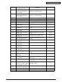
CONTENTS
1.SPECIFICATIONS/SYSTEM LIST................................................................... 1-1
1.1Specifications......................................................................................... 1-1
1.1.1General............................................................................................................ 1-1
1.1.2 HDD Memory Map........................................................................................... 1-2
1.2
2.
System List............................................................................................ 1-3
DISASSEMBLY AND REPLACEMENT.......................................................... 2-1
2.1
Removal and Installation of Options...................................................... 2-1
2.1.1
2.1.2
2.1.3
2.1.4
2.1.5
2.1.6
MJ-1038 (Inner finisher)................................................................................... 2-1
GD-1340 (Fax unit).......................................................................................... 2-3
MY-1046 (Paper feed pedestal)....................................................................... 2-3
GR-1170 (Caster)............................................................................................ 2-4
GR-1160 (Spacer)........................................................................................... 2-5
MJ-1039 (Offline stapler)................................................................................. 2-6
3.SELF-DIAGNOSTIC MODE............................................................................ 3-1
3.1Overview................................................................................................ 3-1
3.2 Service UI.............................................................................................. 3-5
3.2.1Overview.......................................................................................................... 3-5
3.2.2 Login procedure............................................................................................... 3-5
3.2.3 [SERVICE MODE] Screen............................................................................... 3-6
3.2.4 Setting/Changing password............................................................................. 3-6
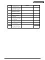
3.3
3.4
3.5
3.6
3.7
3.8
3.9
Input check (Test mode 03).................................................................... 3-7
Output check (test mode 03)................................................................. 3-8
Test print mode (test mode 04).............................................................. 3-9
Operation Procedure in Adjustment Mode (05)................................... 3-10
Test print pattern in Adjustment Mode (05).......................................... 3-12
Operation Procedure in Setting Mode (08).......................................... 3-13
Assist Mode (3C)................................................................................. 3-15
3.9.1 General description........................................................................................ 3-15
3.9.2 Operating Procedure..................................................................................... 3-15
3.9.3Functions....................................................................................................... 3-15
3.10 HDD Assist Mode (4C)........................................................................ 3-18
3.10.1 General description........................................................................................ 3-18
3.10.2 Operation procedure...................................................................................... 3-18
3.10.3Functions....................................................................................................... 3-20
3.11 File System Recovery Mode (5C)........................................................ 3-22
3.11.1Overview........................................................................................................ 3-22
3.11.2 Operation procedure...................................................................................... 3-22
3.11.3Functions....................................................................................................... 3-23
3.12 SRAM Clear Mode (6C)....................................................................... 3-27
3.12.1 General description........................................................................................ 3-27
3.12.2 Operation procedure...................................................................................... 3-27
3.12.3Functions....................................................................................................... 3-28
45641001TH Rev.1
x/
Oki Data CONFIDENTIAL
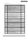
3.13 List print mode (9S)............................................................................. 3-29
3.13.1 Operation procedure...................................................................................... 3-29
3.13.2 List Printing.................................................................................................... 3-30
4.SETTING / ADJUSTMENT.............................................................................. 4-1
4.1
Image Related Adjustment.................................................................... 4-1
4.1.1
4.1.2
4.1.3
4.2
Image Quality Adjustment (Copying Function)...................................... 4-4
4.2.1
4.2.2
4.2.3
4.2.4
4.2.5
4.2.6
4.2.7
4.2.8
4.2.9
4.2.10
4.3
Gamma balance adjustment (Black Mode).................................................... 4-11
Upper limit value in the Toner Saving Mode................................................... 4-12
Thin line width lower limit adjustment............................................................ 4-12
Density adjustment of graphic lines (1200 dpi).............................................. 4-13
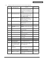
Image Quality Adjustment (Scanning Function).................................. 4-14
4.4.1
4.4.2
4.4.3
4.4.4
4.4.5
4.4.6
4.4.7
4.4.8
4.4.9
4.4.10
4.4.11
4.4.12
4.4.13
4.4.14
4.4.15
4.5
Automatic gamma adjustment......................................................................... 4-4
Density adjustment.......................................................................................... 4-5
Gamma balance adjustment............................................................................ 4-6
Background adjustment................................................................................... 4-7
Judgment threshold for ACS (common for copy and scan).............................. 4-7
Sharpness adjustment..................................................................................... 4-8
Setting range correction................................................................................... 4-8
Adjustment of smudged/faint text..................................................................... 4-9
Judgment threshold adjustment for blank originals
(common for copy and scan)........................................................................... 4-9
Background offsetting adjustment for RADF
(common for copy, scan and fax).................................................................. 4-10
Image Quality Adjustment (Printing Function)..................................... 4-11
4.3.1
4.3.2
4.3.3
4.3.4
4.4
Adjustment Order............................................................................................. 4-1
Image Dimensional Adjustment....................................................................... 4-2
Image dimensional adjustment in the copy/printer/fax function....................... 4-3
Gamma balance adjustment.......................................................................... 4-14
Density adjustment........................................................................................ 4-15
Background adjustment (Color Mode)........................................................... 4-16
Background adjustment (Black/Grayscale).................................................... 4-16
Judgment threshold for ACS (common for copy and network scan).............. 4-17
Sharpness adjustment................................................................................... 4-17
Fine adjustment of black density.................................................................... 4-18
RGB conversion method selection................................................................. 4-18
Adjustment of saturation................................................................................ 4-19
Background offsetting adjustment for RADF
(common for copy, scan and fax)................................................................... 4-19
Adjustment of the capacity and image quality of SlimPDF............................ 4-20
Surrounding void amount adjustment............................................................ 4-20
Judgment threshold adjustment for blank originals
(common for copy and scan)......................................................................... 4-21
JPEG compression level adjustment............................................................. 4-21
Color conversion table selection.................................................................... 4-22
Image Quality Adjustment (FAX Function)........................................... 4-23
4.5.1
4.5.2
45641001TH Rev.1
Density adjustment........................................................................................ 4-23
Background offsetting adjustment for RADF
(common for copy, scan and fax)................................................................... 4-24
xi /
Oki Data CONFIDENTIAL
5.ERROR CODE AND TROUBLESHOOTING................................................... 5-1
5.1
General Descriptions............................................................................. 5-1
5.1.1
5.1.2
5.2
If a problem continues even after performing all troubleshooting..................... 5-1
Collection of debug logs with a USB device.................................................... 5-2
Error Code List....................................................................................... 5-4
5.2.1Jam.................................................................................................................. 5-4
5.2.2 Service call...................................................................................................... 5-5
5.2.3 Error in Internet FAX / Scanning Function....................................................... 5-8
5.2.4 Printer function error...................................................................................... 5-17
5.2.5 Web Page related error/Communication error with external application........ 5-19
5.2.6 MFP access error.......................................................................................... 5-20
5.2.7 Maintenance error.......................................................................................... 5-21
5.2.8 Network error................................................................................................. 5-22
5.2.9 Error history................................................................................................... 5-25
5.3
Diagnosis and Prescription for Each Error Code................................. 5-27
5.3.1
5.3.2
5.3.3
5.3.4
5.3.5
5.3.6
5.3.7
5.3.8
5.3.9
5.3.10
5.3.11
5.3.12
5.3.13
5.4
Other errors....................................................................................... 5-103
5.4.1
5.4.2
5.4.3
5.4.4
6.
Check item..................................................................................................... 5-27
Paper jam in finisher section.......................................................................... 5-28
Finisher related service call........................................................................... 5-32
Communication related service call............................................................... 5-40
Scanner related service call........................................................................... 5-42
Circuit related service call.............................................................................. 5-43
Other service call........................................................................................... 5-44
Error in Internet FAX / Scanning Function..................................................... 5-67
Printer function error...................................................................................... 5-79
Web Page related error/Communication error with external application........ 5-82
MFP access error.......................................................................................... 5-86
Maintenance error.......................................................................................... 5-88
Network error................................................................................................. 5-93
Equipment operation disabled after the installation of option(s).................. 5-103
Wireless LAN connection disabled.............................................................. 5-103
“Invalid Department Code” is displayed....................................................... 5-103
Ethernet disabled in half-duplex communication......................................... 5-103
REPLACEMENT OF PC BOARDS/HDD......................................................... 6-1
6.1
Removal and Installation of PC Boards/HDD........................................ 6-1
6.1.1
6.1.2
6.1.3
6.1.4
6.1.5
6.1.6
6.2
Right side cover............................................................................................... 6-1
SYS Board cover............................................................................................. 6-4
SYS board....................................................................................................... 6-5
Hard disk (HDD).............................................................................................. 6-6
SRAM board <for SYS board>......................................................................... 6-8
FAX unit........................................................................................................... 6-9
Precautions, Procedures and Settings for
Replacing PC Boards and HDD........................................................... 6-10
6.2.1
6.2.2
6.2.3
45641001TH Rev.1
Precautions when replacing PC boards......................................................... 6-10
HDD fault diagnosis....................................................................................... 6-11
Precautions and procedures when replacing the HDD.................................. 6-13
xii /
Oki Data CONFIDENTIAL
6.2.4
6.2.5
6.2.6
6.2.7
6.2.8
6.2.9
6.3
Precautions for Installation of GP-1070 and Disposal of HDD/ Board... 6-31
6.3.1
6.3.2
6.3.3
6.3.4
7.
Precautions and Procedures when replacing the SYS board........................ 6-18
Precautions and procedure when replacing the SRAM board
(for the SYS board)........................................................................................ 6-22
Precautions and Procedures when replacing the PU board.......................... 6-28
Precautions and Procedures when replacing the SU board.......................... 6-28
Firmware confirmation after the PC board/HDD replacement....................... 6-28
License re-registration using the one-time dongle......................................... 6-29
Precautions for Installation of GP-1070......................................................... 6-31
Precautions when disposing of HDD............................................................. 6-31
Precautions when disposing of the SYS board.............................................. 6-31
Precautions when disposing of the SRAM board (for SYS board)................. 6-31
REMOTE SERVICE......................................................................................... 7-1
7.1
Auto Supply Order................................................................................. 7-1
7.1.1Outline............................................................................................................. 7-1
7.1.2 Setting Item...................................................................................................... 7-1
7.1.3 Setting procedure............................................................................................ 7-4
7.1.4 Order Sheet Format....................................................................................... 7-13
7.2
Service Notification.............................................................................. 7-17
7.2.1Outline........................................................................................................... 7-17
7.2.2Setting............................................................................................................ 7-17
7.2.3 Items to be notified........................................................................................ 7-23
8.
FIRMWARE UPDATING.................................................................................. 8-1
8.1
8.2
Overview................................................................................................ 8-1
Firmware Updating with USB Device..................................................... 8-3
8.2.1
8.2.2
8.3
Patch Updating with USB Device......................................................... 8-13
8.3.1
8.3.2
8.4
FAX unit firmware (GD-1340)........................................................................ 8-26
Confirmation of the updated data........................................................ 8-28
When Firmware Updating Fails............................................................ 8-29
8.7.1
8.7.2
9.
Writing the data to the download jig (PWA-DWNLD-JIG2)............................ 8-21
System firmware............................................................................................ 8-23
Firmware Updating with K-PWA-DLM-320.......................................... 8-25
8.5.1
8.6
8.7
Firmware type and data file name for patch updating.................................... 8-13
Update procedure.......................................................................................... 8-15
Firmware Updating with PWA-DWNLD-JIG2....................................... 8-20
8.4.1
8.4.2
8.5
Firmware type and data file name for updating................................................ 8-3
Update procedure............................................................................................ 8-5
Procedure...................................................................................................... 8-29
Flow chart for correcting USB update failure................................................. 8-30
BACKUP FUNCTION...................................................................................... 9-1
9.1
Data Cloning.......................................................................................... 9-1
9.1.1 General description.......................................................................................... 9-1
9.1.2Precautions...................................................................................................... 9-1
45641001TH Rev.1
xiii /
Oki Data CONFIDENTIAL
9.1.3
9.1.4
9.2
AES Data Encryption Function Setting.................................................. 9-5
9.2.1
9.2.2
9.2.3
9.2.4
9.2.5
9.3
Backup files..................................................................................................... 9-2
Cloning procedure........................................................................................... 9-2
General description......................................................................................... 9-5
Precautions..................................................................................................... 9-5
Setting procedure............................................................................................ 9-6
Procedure for disabling data encryption function........................................... 9-10
Procedure for discarding HDD when data encryption function is enabled..... 9-10
High Security Mode............................................................................. 9-11
9.3.1 General description........................................................................................ 9-11
9.3.2 Prior confirmation.......................................................................................... 9-11
9.3.3 Procedure for entering the High Security Mode............................................. 9-11
9.3.4Precautions.................................................................................................... 9-12
10.EXTERNAL COUNTERS.............................................................................. 10-1
10.1Outline................................................................................................. 10-1
10.2Signal................................................................................................... 10-1
10.2.1 Pin Layout...................................................................................................... 10-1
10.2.2 Details of the signals...................................................................................... 10-3
10.3Notices................................................................................................. 10-5
10.3.1 Setting code................................................................................................... 10-5
10.3.2 Setting value change and restrictions when using the coin controller........... 10-5
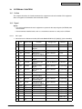
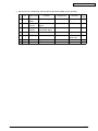
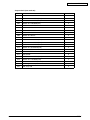
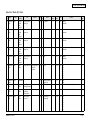
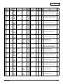
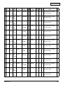
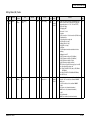
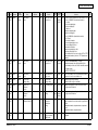
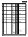
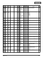
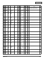
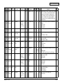
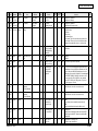
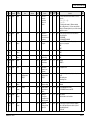
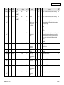
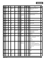
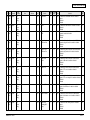
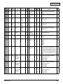
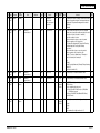
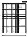
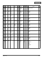
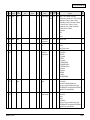
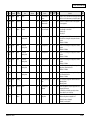
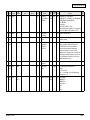
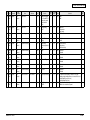
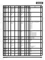
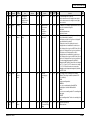
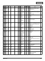
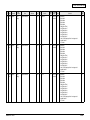
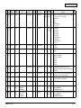
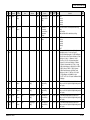
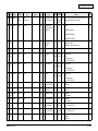
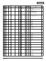
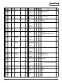
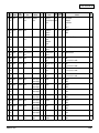
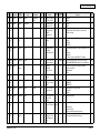
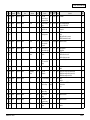
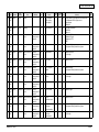
11.SELF-DIAGNOSIS CODE (03/05/08 CODE)................................................ 11-1
Test mode (03)............................................................................................... 11-1
Adjustment Mode (05) Codes........................................................................ 11-3
Setting Mode (08) Codes............................................................................. 11-19
45641001TH Rev.1
xiv /
Oki Data CONFIDENTIAL
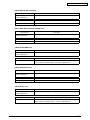
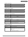
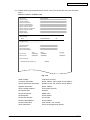
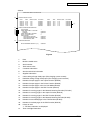
1.SPECIFICATIONS/SYSTEM LIST
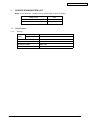
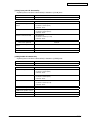
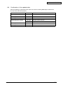
Notes:In this document, a model name is replaced with an alias as follows:
Model name
Alias
MB760
H-290
MB770, ES7170MFP, MPS5502mb
H-291
1.1Specifications
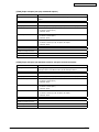
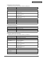
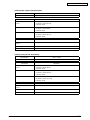
1.1.1General
Memory
(RAM)
Main memory
2 GB
Page Memory
None
HDD
160 GB
Account Codes
10000 codes
Department Codes
1000 codes
Machine version
OEL, ODA, AOS
45641001TH Rev.1
1-1 /
Oki Data CONFIDENTIAL
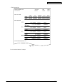
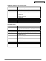
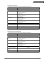
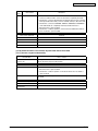
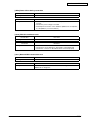
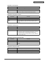
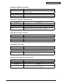
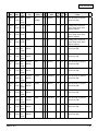
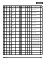
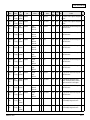
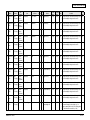
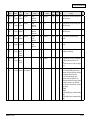
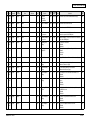
1.1.2
HDD Memory Map
Category
HDD
Item
Unit
HDD
HDD
GB
160
Copy
Memory copy
GB
30
Box
e-Filing
GB
80 (Shared with e-filing/Storage file)
Public box
Box
1
User box
Box
200
Folders per box
Folder
100
Documents per box
Document
400
Pages per document
Page
200
Number of maximum jobs Job
Scan
Scan to File
Pages per job
GB
80
Page
1000
Number of maximum jobs Job
FAX
Print
899 (Except Print/FAX/interrupt)
FAX Transmission
GB
1 (Shared with Rx and Tx)
FAX Reception
GB
1 (Shared with Rx and Tx)
Printer Data Spool
GB
25
Job
Storage full
Pages per job
Number of maximum jobs Job
Job area
Pages per job
1000
GB
80 (Shared with e-filing/Storage file)
Job
Storage full
Number of maximum jobs Job
45641001TH Rev.1
899
1000
1-2 /
Oki Data CONFIDENTIAL
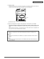
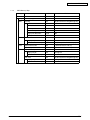
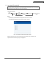
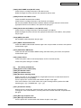
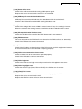
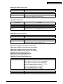
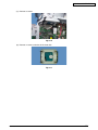
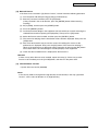
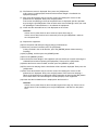
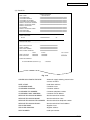
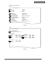
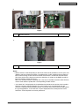
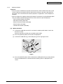
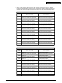
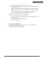
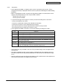
1.2 System List
e-BRIDGE ID Gate
KP-2004
Antenna
GN-3010
Harness kit for
coin controller
GQ-1260
e-BRIDGE ID Gate
KP-2005
Wireless
LAN module
GN-1060
Damper Kit
KK-1003
Inner
Finisher
MJ-1038
Meta Scan Enabler
GS-1010
External Interface
Enabler
GS-1020
Staple
Cartridge
STAPLE-2000
Data overwrite
Enabler
GP-1070
Offline
Stapler
MJ-1039
IP Sec Enabler
GP-1080
Unicode Font
Enabler
GS-1007
Staple
Cartridge
STAPLE-3700
FAX Unit
GD-1340NA/EU/AU
Spacer
GR-1160
Paper Feed
Pedestal (PFP)
MY-1046
Large Capacity
Feeder (LCF)
KD-1040
Caster
GR-1170
Desk
MH-3400
Fig. 1-1
Notes:
• The antenna (GN-3010) is necessary to enable the wireless LAN module (GN-1060/C).
45641001TH Rev.1
1-3 /
Oki Data CONFIDENTIAL
2.
DISASSEMBLY AND REPLACEMENT
2.1 Removal and Installation of Options
Important:
• Before installing or removing options, turn the main power switch off and disconnect the
2 power cable from the outlet.
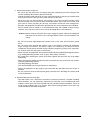
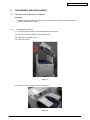
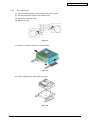
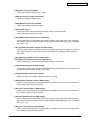
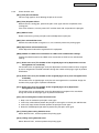
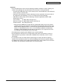
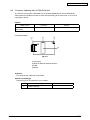
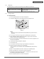
2.1.1
MJ-1038 (Inner finisher)
(1) Press the [Power] button on the control panel to shut it down.
(2) Turn the main power switch of the equipment off.
(3) Disconnect the power cable.
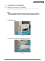
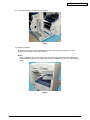
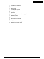
(4) Open the scanner.
Fig. 2-1
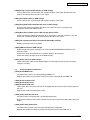
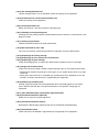
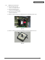
(5) Remove 2 screws and take off the stacker tray.
Fig. 2-2
45641001TH Rev.1
2-1 /
Oki Data CONFIDENTIAL
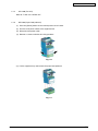
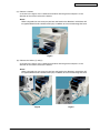
(6) Take off the connector cover.
Fig. 2-3
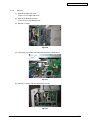
(7) Disconnect the connector.
Fig. 2-4
(8) Remove 2 screws and take off the finisher.
Fig. 2-5
45641001TH Rev.1
2-2 /
Oki Data CONFIDENTIAL
2.1.2
GD-1340 (Fax unit)
Refer to P. 6-9 “6.1.6 FAX unit”.
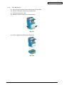
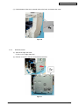
2.1.3
MY-1046 (Paper feed pedestal)
(1) Press the [Power] button on the control panel to shut it down.
(2) Turn the main power switch of the equipment off.
(3) Disconnect the power cable.
(4) Remove 2 screws and take off 2 fixing brackets.
Fig. 2-6
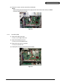
(5) Lift the equipment up and remove the paper feed pedestal.
Fig. 2-7
45641001TH Rev.1
2-3 /
Oki Data CONFIDENTIAL
2.1.4
GR-1170 (Caster)
(1) Press the [Power] button on the control panel to shut it down.
(2) Turn the main power switch of the equipment off.
(3) Disconnect the power cable.
(4) Release the lock.
Fig. 2-8
(5) Remove 2 screws and take off 2 fixing brackets.
Fig. 2-9
(6) Lift the equipment up and remove the caster.
Fig. 2-10
45641001TH Rev.1
2-4 /
Oki Data CONFIDENTIAL
2.1.5
GR-1160 (Spacer)
(1) Press the [Power] button on the control panel to shut it down.
(2) Turn the main power switch of the equipment off.
(3) Disconnect the power cable.
(4) Remove 2 screws and take off 2 fixing brackets.
Fig. 2-11
(5) Lift the equipment up and remove the spacer.
Fig. 2-12
45641001TH Rev.1
2-5 /
Oki Data CONFIDENTIAL
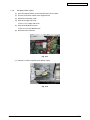
2.1.6
MJ-1039 (Offline stapler)
(1) Press the [Power] button on the control panel to shut it down.
(2) Turn the main power switch of the equipment off.
(3) Disconnect the power cable.
(4) Take off the right side cover.
& P. 6-1 “6.1.1 Right side cover”
(5) Take off the SYS board cover.
& P. 6-4 “6.1.2 SYS Board cover”
(6) Disconnect the connector.
Fig. 2-13
(7) Remove 2 screws and take off the offline stapler.
Fig. 2-14
45641001TH Rev.1
2-6 /
Oki Data CONFIDENTIAL
3.SELF-DIAGNOSTIC MODE
3.1Overview
[A] Starting each mode
To enter the desired mode, turn the power ON while pressing two digital keys designated to
each mode (e.g. [0] and [5]) simultaneously. Hold the two keys until the [PRINT DATA] lamp is lit.
On the authentication screen displayed after starting up each mode, enter the service password,
and then press [OK]. The password is not set by default.
Refer to “Appendix” for the codes in Test mode (03), Test print mode (04), Adjustment mode (05),
and Setting mode (08).
[B] Exiting from each mode
Shut down the equipment. When the power should be turned OFF, be sure to shut down the
equipment by pressing the [ON/OFF] button for a few seconds.
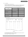
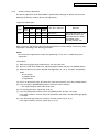
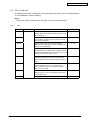
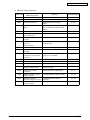
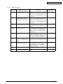
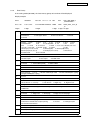
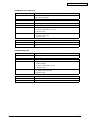
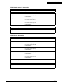
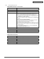
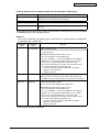
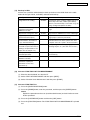
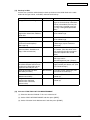
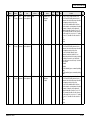
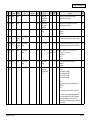
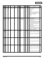
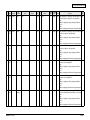
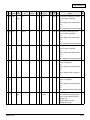
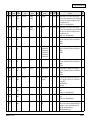
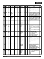
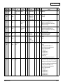
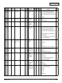
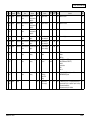
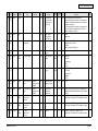
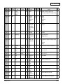
[C] List of modes
Mode
For start
Contents
For exit
Display
Control panel
check mode
[0] + [1] +
[POWER]
All LEDs on the control panel are lit, and all
the LCD pixels blink.
[POWER]
OFF/ON
-
Test mode
[0] + [3] +
[POWER]
Checks the status of input/output signals.
[POWER]
OFF/ON
100% C
TEST MODE
Test print
mode
[0] + [4] +
[POWER]
Outputs the test patterns.
[POWER]
OFF/ON
100% P A4
TEST PRINT
Adjustment
mode
[0] + [5] +
[POWER]
Adjusts various items.
[POWER]
OFF/ON
100% A A4
TEST MODE
Setting mode
[0] + [8] +
[POWER]
Sets various items.
[POWER]
OFF/ON
100% D
TEST MODE
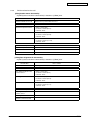
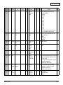
Maintenance
mode
[6]+[8]+
[POWER]
Maintains the scanner unit (SU) and printer
unit (PU)
[POWER]
OFF/ON
-
Assist mode
[3]+[C]+
[POWER]
Clears error flags or SRAM, or safely deletes [POWER]
OFF/ON
data in the HDD or SRAM to support the
replacement of the SYS board, SRAM or
HDD.
-
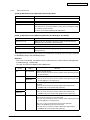
HDD assist
mode
[4]+[CLEAR]+
[POWER]
Assists the ADI-HDD by checking the type
of the mounted HDD, reverting the HDD to a
factory default or removing keys.
[POWER]
OFF/ON
-
File system
[5] + [C] +
recovery mode [POWER]
Checks, recovers or initializes the file system [POWER]
(HDD).
OFF/ON
-
SRAM clear
mode
Recovers the equipment from particular
errors such as F800 or F900.
[POWER]
OFF/ON
-
List print mode [9] + [START]
+ [POWER]
Prints various lists or outputs them in a CSV
format.
[POWER]
OFF/ON
Firmware
update mode
[4] + [9] +
[POWER]
Performs firmware update with USB device.
[POWER]
OFF/ON
-
[8] + [9] +
[POWER]
Performs firmware update with download jig.
[POWER]
OFF/ON
-
Password
reset mode
[4] + [8] + [9]
+ [POWER]
Resets the administrator password and
service password.
[POWER]
OFF/ON
-
SRAM data
cloning mode
[5] + [9]
+ [POWER]
Backs up the SRAM data to USB device.
[POWER]
OFF/ON
-
45641001TH Rev.1
[6]+[CLEAR]+
[POWER]
100% L A4
LIST PRINT
3-1 /
Oki Data CONFIDENTIAL
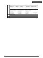
Note:
Do not enter any of the modes shown below since they are provided only for production. If you
do so, the equipment may not be restarted.
[2]+[CLEAR]+[POWER]
[7]+[CLEAR]+[POWER]
[8]+[CLEAR]+[POWER]
[9]+[CLEAR]+[POWER]
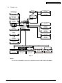
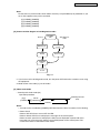
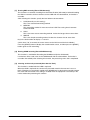
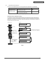
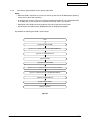
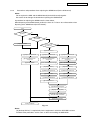
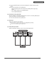
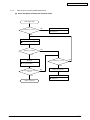
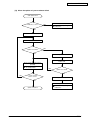
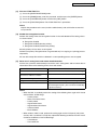
[D] State transition diagram of self-diagnosis modes
[POWER]
ON
Normal
Self-diagnosis
mode
Authentication
screen
Warming up
Each mode
Ready
*2
[POWER]
OFF
*1
To user
Fig. 3-1
*1 If you have used a self-diagnostic mode, turn the power OFF before the customer starts using
the equipment
*2 Mode shown in the table “[C] List of modes”
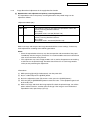
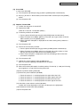
[E] About each mode
• Control panel check mode (01)
Operation procedure
[0][1]
[POWER]
LED lit/
LCD blinking
[START]
(Button check)
[POWER] OFF/ON
(Exit)
[START]
Notes:
• A mode can be cancelled by [POWER] OFF/ON when the LED is lit and the LCD is blinking.
• Button Check
Buttons with LED: Press to turn OFF the LED.
Buttons without LED: Press to display the message on the control panel.
Button on touch panel: Press to display the initial screen displayed at power-ON. Press
[execution] on the touch panel and then the [CLEAR] button on the control panel. The
screen then returns to the Button Check menu.
45641001TH Rev.1
3-2 /
Oki Data CONFIDENTIAL
• Test mode (03)
Refer to & P. 3-7 “3.3 Input check (Test mode 03)” and & P. 3-9 “3.4 Output check (test mode
03)”.
• Test print mode (04)
Refer to & P. 3-9 “3.5 Test print mode (test mode 04)”.
• Adjustment mode (05)
Refer to & P. 3-10 “3.6 Operation Procedure in Adjustment Mode (05)”, & P. 3-12 “3.7 Test
print pattern in Adjustment Mode (05)”, and “Appendix” - “Adjustment Code (05).”
Notes:
When the power should be turned OFF, be sure to shut down the equipment by pressing
the [ON/OFF] button for a few seconds.
Remarks:
• In “RAM”, the SRAM of the board in which the data of each code is stored is indicated. “PU”
stands for the PU board and “SYS” stands for the SYS board.
• Setting mode (08)
Refer to & P. 3-13 “3.8 Operation Procedure in Setting Mode (08)” and “Appendix” - “Setting
Code (08).”
Notes:
When the power should be turned OFF, be sure to shut down the equipment by pressing
the [ON/OFF] button for a few seconds.
Remarks:
• In “RAM”, the SRAM of the board in which the data of each code is stored is indicated. “PU”
stands for the PU board, “SYS”, “NIC” or “UTY” stands for the SYS board.
• Maintenance mode (68)
Refer to “5.2 Maintenance menu functions” in the Hardware Guide.
• Assist mode (3C)
Refer to & P. 3-15 “3.9 Assist Mode (3C)”.
• HDD assist mode (4C)
Refer to & P. 3-18 “3.10 HDD Assist Mode (4C)”.
• File system recovery mode (5C)
Refer to & P. 3-23 “3.11 File System Recovery Mode (5C)”.
• SRAM clear mode (6C)
Refer to & P. 3-27 “3.12 SRAM Clear Mode (6C)”.
• List print mode (9S)
Refer to & P. 3-29 “3.13 List print mode (9S)”.
• Firmware update mode (49/89)
Refer to & P. 8-1 “8. FIRMWARE UPDATING”.
45641001TH Rev.1
3-3 /
Oki Data CONFIDENTIAL
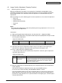
• Password reset mode (489)
This mode resets the administrator password and service password. The user data is erased
when resetting the passwords.
Operation procedure
[4][8][9]
[POWER]
(Operation started)
[POWER] OFF/ON
(Exit)
• SRAM data cloning mode (59)
Refer to P. 9-1 “9.1 Data Cloning”.
45641001TH Rev.1
3-4 /
Oki Data CONFIDENTIAL
3.2 Service UI
3.2.1Overview
The following self-diagnostic modes can be used with Service UI on the touch panel of the
control panel.
• 05 ADJUSTMENT MODE
• 08 SETTING MODE
• FAX LIST PRINT MODE
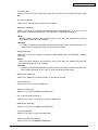
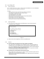
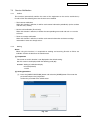
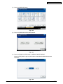
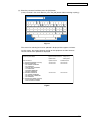
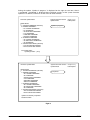
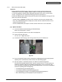
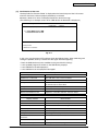
3.2.2
Login procedure
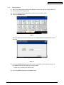
[ 1 ] In the normal mode
(1) Turn the power ON.
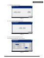
(2) Press the [USER FUNCTIONS] button.
(3) With the [USER FUNCTIONS] menu displayed, enter the Service Mode password provided
during product training.
Fig. 3-2
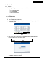
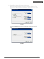
(4) Enter the user name and password on the SERVICE TECHNICIAN PASSWORD screen,
then press [OK]. They are set by default as follows:
User Name
Service
Password
None
Fig. 3-3
The SERVICE MODE screen is displayed.
45641001TH Rev.1
3-5 /
Oki Data CONFIDENTIAL
[2] In the security mode
If the security mode (the value of 08-8911 is “3”) is set, log into Service UI following the steps
below.
(1) Turn the power ON.
(2) Enter the user name and password on the USER AUTHENTICATION screen. The password
needs to be changed to log in for the first time.
Notes:
In case the password is forgotten, ask the administrator to reset the service password. In
case both the service password and administrator password are forgotten, the passwords
can be reset in the password reset mode. Note that the user data are deleted at that time.
(3) Press the [USER FUNCTIONS] button.
(4) Enter the password for Service UI on the USER FUNCTIONS screen. The SERVICE MODE
screen is displayed.
3.2.3
[SERVICE MODE] Screen
After selecting the mode and pressing the [NEXT] button, the screen is switched to the selected
mode.
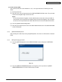
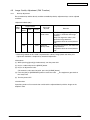
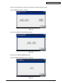
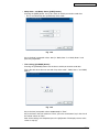
3.2.4
Setting/Changing password
(1) Press the [SETTINGS] button on the SERVICE MODE screen to display the SETTINGS
screen.
Fig. 3-4
(2) Press the [SERVICE PASSWORD] button to change the service password, or [RESET
ADMIN PASSWORD] to reset the administrator password.
45641001TH Rev.1
3-6 /
Oki Data CONFIDENTIAL
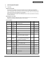
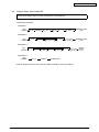
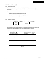
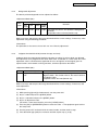
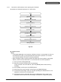
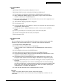
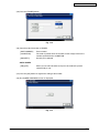
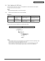
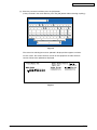
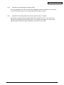
3.3 Input check (Test mode 03)
The status of each input signal can be checked by pressing the [FAX] button, [COPY] button,
[SCAN] button and the digital keys in the test mode (03).
<Operation procedure>
[0][3]
[POWER]
[START]
[CLEAR]
[FAX]
[COPY]
or
[SCAN]
[Digital keys]
(LCD ON)
[CLEAR]
[POWER] OFF/ON
(Exit)
Notes:
• Initialization is performed before the equipment enters the test mode.
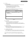
• The PRINT DATA lamp blinks when the input check is running.
Fig. 3-5 Example of display during input check
Refer to “Appendix” in this manual for the items to be checked and the condition of the
equipment when the buttons [A] to [H] are highlighted.
45641001TH Rev.1
3-7 /
Oki Data CONFIDENTIAL
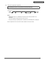
3.4 Output check (test mode 03)
Status of the output signals can be checked in the test mode 03.
<Operation procedure>
Procedure 1
[0][3]
[POWER]
(Code)
Operation
ON
[START]
Stop
code
[START]
Operation
OFF
[POWER] OFF/ON
(Exit)
Procedure 2
[0][3]
[POWER]
(Code)
[START]
Operation
One direction
[CLEAR]
Test mode
standby
[POWER] OFF/ON
(Exit)
Procedure 3
[0][3]
[POWER]
(Code)
[START]
Operation
ON
[START]
Operation
OFF
[CLEAR]
Test mode
standby
[POWER]
OFF/ON
(Exit)
Procedure 4
[0][3]
[POWER]
(Code)
[START]
[POWER] OFF
Refer to “Appendix” in this manual for the codes available in the test mode 03.
45641001TH Rev.1
3-8 /
Oki Data CONFIDENTIAL
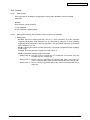
3.5 Test print mode (test mode 04)
The embedded test pattern can be printed out in the test print mode (04).
<Procedure 1>
[0][4]
[POWER]
(Code)
(Media selection)
[START]
Operation
Continuous
Test Printing
[CLEAR]
[POWER]
OFF/ON
(Exit)
Notes:
• When an error occurs, it is indicated on the panel, but the recovery operation is not
performed.
Turn OFF the power and then back ON to clear the error.
• During test printing, the [CLEAR] button is disabled when “Wait adding toner” is displayed.
Refer to “Appendix” in this manual for the codes available in the test print mode.
45641001TH Rev.1
3-9 /
Oki Data CONFIDENTIAL
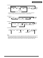
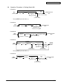
3.6 Operation Procedure in Adjustment Mode (05)
Procedure 1
[Digital key]
(Code)
[0][5]
[POWER]
[Digital key]
*[FUNCTION CLEAR]
(Key in a value)
[START]
[CANCEL]
[FAX]
[OK]
or
[START]
[INTERRUPT]
(Stores value in RAM) (Test copy)
[POWER]
OFF/ON
(Exit)
[CLEAR] *Press [FUNCTION CLEAR] to enter minus (-).
(Corrects value)
Procedure 2
[0][5]
[POWER]
[Digital key]
(Code)
[START]
[Digital key]
(Code)
[START]
(
Value
displayed
)
[OK]
([FAX] [START])
or
(Test copy)
[INTERRUPT]
(Value unchangeable)
[POWER]
OFF/ON
(Exit)
Procedure 3
[0][5]
[POWER]
[UP]
or
[DOWN]
(Adjust a value)
[CANCEL]
[OK]
([FAX] [START])
or
(Test copy)
[INTERRUPT]
(Stores value in RAM)
[POWER]
OFF/ON
(Exit)
[FUNCTION CLEAR]
(Corrects value)
Procedure 4
[CANCEL]
[0][5]
[POWER]
[Digital key]
(Code)
[START]
[START]
([FAX]
[OK]
or
[START] [Digital key]
[POWER]
[INTERRUPT]
OFF/ON
[START])
*[FUNCTION CLEAR]
Stores value (Test copy)
(Exit)
(Key in a value)
in RAM
[CLEAR]
(Corrects value)
[CLEAR]
(Corrects value)
*Press [FUNCTION CLEAR] to enter minus (-).
[Digital key]
(Sub code)
Procedure 5
[CANCEL]
[0][5]
[POWER]
[Digital key]
(Code)
[START]
Automatic
adjustment
[OK]
or
[INTERRUPT]
Stores value
in RAM
[FAX]
[START]
(Test copy)
[POWER]
OFF/ON
(Exit)
Procedure 6
[0][5]
[POWER]
[Digital key]
(Code)
[START]
Automatic
adjustment
[FAX] [COPY])
(Test copy)
[POWER]OFF/ON
(Exit)
*[CANCEL] or [CLEAR]
* When the automatic adjustment ends abnormally, an error message is displayed.
* Return to standby screen by pressing the [CANCEL] or [CLEAR] button.
45641001TH Rev.1
3-10 /
Oki Data CONFIDENTIAL
Procedure 7
[CANCEL]
[Digital key]
[Digital key]
[0][5]
[START]
(Code)
(Sub code)
[POWER]
[START]
Automatic
adjustment
[FAX]
[OK]
Stores value
in RAM
[START]
(Test copy)
[CLEAR]
(Corrects value)
[POWER]
OFF/ON
(Exit)
*[CANCEL] or [CLEAR]
* When the automatic adjustment ends abnormally, an error message is displayed.
* Return to standby screen by pressing the [CANCEL] or [CLEAR] button.
Procedure 10
[0][5]
[POWER]
[Digital key]
(Code)
[Digital key]
(Sub code)
[START]
[START]
Value
displayed
[START]
[OK] or [INTERRUPT]
(Value unchangeable)
[POWER]
OFF/ON
(Exit)
Procedure 12
[Digital key]
(Code)
[0][5]
[POWER]
[START]
[Digital key]
(Key in a value)
[CANCEL]
[FAX]
[OK]
or
[START]
[INTERRUPT]
(Stores value in RAM) (Test copy)
Manual
adjustment
[CLEAR]
(Corrects value)
[POWER]
OFF/ON
(Exit)
Procedure 14
[0][5]
[POWER]
[Digital key]
(Code)
[START]
[Digital key]
(Sub code)
[START]
[CLEAR]
(Corrects value)
[OK]
or
[INTERRUPT]
Stores value
in RAM
[FUNCTION CLEAR]
(Corrects value)
(Input value)
[FAX]
[START]
(Test copy)
[POWER]
OFF/ON
(Exit)
Notes:
The fuser belt temperature control at the adjustment mode is different from that at the normal
state. Therefore, the problem of fusing efficiency may be occurred in the test copy at the
adjustment mode. In that case, turn ON the power normally, leave the equipment for approx. 3
minutes after it has become ready state and then start up the adjustment mode again.
45641001TH Rev.1
3-11 /
Oki Data CONFIDENTIAL
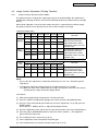
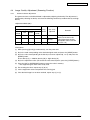
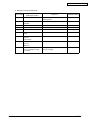
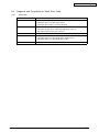
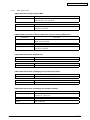
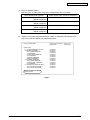
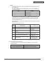
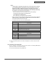
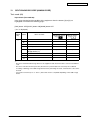
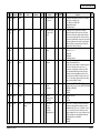
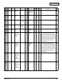
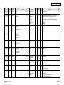
3.7 Test print pattern in Adjustment Mode (05)
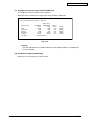
Operation:
One test print is printed out when the [FAX] button is pressed after the code is keyed in at
Standby Screen.
Code
Types of test pattern
Remarks
6
Copier gamma confirmation pattern
(Black / All media types)
For confirming the reproduction of gradatin
10
Copier gamma adjustment pattern
(Black / All media types)
Refer to 4.2.1 Automatic gamma adjustment
45641001TH Rev.1
3-12 /
Oki Data CONFIDENTIAL
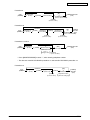
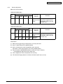
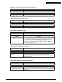
3.8 Operation Procedure in Setting Mode (08)
Procedure 1
[CANCEL]
[Digital key]
(Code)
[0][8]
[POWER]
[Digital key]
*[FUNCTION CLEAR]
Sets or
changes value
[START]
[OK]
[POWER] OFF/ON
or
(Exit)
[INTERRUPT]
(Stores value in RAM)
[CLEAR]
(Corrects value)
* Press [RESET] to enter minus (-).
Procedure 2
[0][8]
[POWER]
[Digital key]
(Code)
[START]
[OK]
or
[INTERRUPT]
Adjustment value
cannot be changed
[POWER]OFF/ON
(Exit)
Procedure 3
[0][8]
[POWER]
[Digital key]
(Code)
[INITIALIZE]
or
(Automatic setting)
[INTERRUPT]
(Stores value in RAM)
[START]
[CANCEL] or [CLEAR]
[POWER] OFF/ON
(Exit)
Procedure 4
[CANCEL]
[START]
[0][8]
[POWER]
[Digital key]
(Code)
[START]
[Digital key]
(Sub-code)
[START]
[CLEAR]
(Corrects value)
[OK]
or
[Digital key]
* [FUNCTION CLEAR] [INTERRUPT]
(Stores value
Sets or
in RAM)
changes value
[CLEAR]
(Corrects value)
[POWER]
OFF/ON
(Exit)
* Press [RESET] to enter minus (-).
Procedure 5
[CANCEL]
[0][8]
[POWER]
[Digital key]
(Code)
[START]
[Digital key]
Sets or
changes value
[OK]
[POWER] OFF/ON
or
(Exit)
[INTERRUPT]
(Stores value in RAM)
[CLEAR]
(Corrects value)
45641001TH Rev.1
3-13 /
Oki Data CONFIDENTIAL
Procedure 9
[CANCEL]
[0][8]
[POWER]
[Digital key]
(Code)
[START]
[OK]
[POWER] OFF/ON
or
(Exit)
[INTERRUPT]
(Stores value in RAM)
[CLEAR]
(Corrects value)
[Select button]
Procedure 10
[CANCEL]
[0][8]
[POWER]
[Digital key]
(Code)
[START]
[Digital key]
(1st setting)
[START]
[OK]
[POWER]
or
OFF/ON
[INTERRUPT]
(Exit)
(Stores value in RAM)
[CLEAR]
(Corrects value)
[Digital key]
(2nd setting)
[CLEAR]
(Corrects value)
Procedure 11 and 12
[CANCEL]
[0][8]
[POWER]
[Digital key]
(Code)
[Digital key]
or
[OK]
[START]
[Software keyboard] *2(Stores value in RAM)
*1 [MONITOR/PAUSE]
Sets or
changes value [CLEAR]
(Corrects value)
[POWER] OFF/ON
(Exit)
* Press [MONITOR/PAUSE] to enter “-”, when entering telephone number.
* The data are stored in SYS-RAM in procedure 11 and stored in NIC-RAM in procedure 12.
Procedure 14
[CANCEL]
[0][8]
[POWER]
[Digital key]
(Code)
[START]
[Digital key]
(Sub-code)
[START]
[CLEAR]
(Corrects value)
45641001TH Rev.1
[OK]
or
[INTERRUPT]
Adjustment value
cannot be changed
[POWER]
OFF/ON
(Exit)
3-14 /
Oki Data CONFIDENTIAL
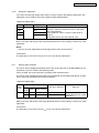
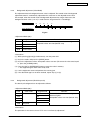
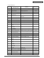
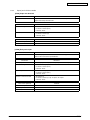
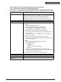
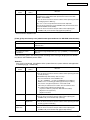
3.9 Assist Mode (3C)
3.9.1
General description
This is a mode to operate the partitions of HDD, initialize the SRAM data, erase the HDD/SRAM
data, back up/restore the encryption key and licences.
Functions:
• Clearing update error flag (Clear Error Flag in Software Installation)
• Formatting data storage partition (Format Root Partition)
• Creating HDD partition (Format HDD)
• Formatting SRAM data (Clear SRAM)
• Backing up/restoring encryption key and license (Key Backup Restore)
• Erasing HDD securely (Erase HDD Securely)
• Erasing SRAM securely (Erase SRAM Securely)
• Clearing service tech password (Clear Service Tech)
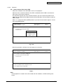
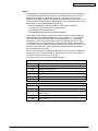
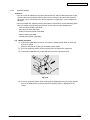
3.9.2
Operating Procedure
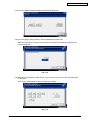
(1) Turn ON the power while [3] button and [CLEAR] button are pressed simultaneously.
The following screen is displayed.
Firmware Assist Mode
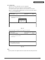
Select number(1-8) and press START key
1. Clear Error Flag in Software Installation
2. Format Root Partition
3. Format HDD
4. Clear SRAM
5. Key Backup Restore
6. Erase HDD Securely
7. Erase SRAM Securely
8. Clear Service Tech Password
Fig. 3-6
(2) Select the item with the digital keys and press the [START] button.
3.9.3Functions
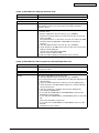
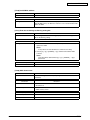
[A] Clearing update error flag (Clear Error Flag in Software Installation)
Even if the firmware downloading has been completed normally, the Recovery Mode may
accidentally start up and an F600 error occurs when the power is turned ON again. In this
case, clear the Update Error flags used in the download process with this function. (Normally,
the flags are automatically cleared in the download process.)
Also in the case the Recovery Mode accidentally starts up after the replacement of SRAM
on the SYS board, the flags are cleared with this function.
[B] Formatting data storage partition (Format Root Partition)
When a defect occurs on the UI data, etc. which are stored in the HDD, the partition with the
stored UI data, etc. is formatted with this function.
Do not use this function since it is not normally necessary. HDD data must be installed after
performing this function.
45641001TH Rev.1
3-15 /
Oki Data CONFIDENTIAL
[C] Creating HDD partition (Format HDD)
When the HDD is replaced or UI data, etc. are downloaded using the USB storage, it is
necessary to format a partition in the HDD before downloading. In this case, the partition is
created in the HDD with this function.
Notes:
• When downloading with a download jig, it is not necessary to format a partition in
advance.
• Perform the HDD partition formatting only when a new HDD is installed since all data in
the current HDD are erased by this operation.
[D] Formatting SRAM data (Clear SRAM)
When SRAM is replaced with a new one, abnormal values may be written in the new SRAM.
SRAM data must be formatted with this function for such case.
Notes:
• This function is required only when a new SRAM is installed.
• Do not perform this function in cases other than the installation of a new SRAM
because all data in the SRAM will be deleted with this function.
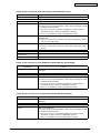
[E] Backing up/restoring encryption key and license (Key Backup Restore)
When the SRAM board (for the SYS board) or the SYS board is replaced or initialized, the
encryption key and license are erased. Therefore, they need to be backed up or restored
with this function.
Configurations and functions of the “5.Key Backup Restore” menu.
1. Key SRAM to FROM
Restore the encryption key from SRAM to FROM.
2. Key FROM to SRAM
Back up the encryption key from FROM to SRAM.
3. License SRAM to FROM
Restore the license from SRAM to FROM.
4. License FROM to SRAM
Back up the license from FROM to SRAM.
5. ADIKey SRAM to FROM
Restore the ADIKey from SRAM to FROM.
6. ADIKey FROM to SRAM
Back up the ADIKey from FROM to SRAM.
45641001TH Rev.1
3-16 /
Oki Data CONFIDENTIAL
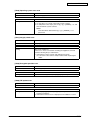
[F] Erasing HDD securely (Erase HDD Securely)
This function is used when installing Data Overwrite Enabler (GP-1070) or before discarding
the HDD. It overwrites all the used areas on the HDD with the selected data, and makes it
unusable.
After selecting this function, specify the level below to be overwritten.
1: LOW (Normally use this setting.)
This is the standard overwriting method.
2:MEDIUM
This overwriting method is more secure than LOW. The erasing time is between
LOW and HIGH.
3:HIGH
This is the most secure overwriting method. It takes the longest time to erase data.
4: SIMPLE
This is the simple overwriting method. It takes the shortest time to erase data.
Key in the level number to display “<” next to it.
(At this time, if “0” is entered, the screen returns to the initial one of the Assist Mode.)
Press the [START] button to display the reconfirmation screen, and then press the [START]
button again to start overwriting.
[G] Erasing SRAM securely (Erase SRAM Securely)
This function is used before discarding the SRAM board (for the SYS board).
It overwrites all the used areas on the SRAM board with the selected data, and makes it
unusable. Immediately after selecting this function, the processing starts and is completed.
[H] Clearing service tech password (Clear Service Tech)
This function is needed after the HDD is replaced.
When the HDD is replaced, the service tech password stored in the new one is set as a
blank. Therefore, its password is copied to the SRAM board so that both passwords become
the same with this function. The setting is enabled when the equipment is started up in the
normal mode after performing this function.
45641001TH Rev.1
3-17 /
Oki Data CONFIDENTIAL
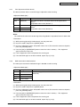
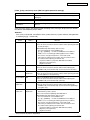
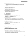
3.10 HDD Assist Mode (4C)
3.10.1
General description
This mode is available only when the security HDD (ADI-HDD) is mounted in the equipment. It
enables you to check the type of the mounted HDD, revert the ADI-HDD to the factory default or
remove keys.
Functions
• Checks the type (ADI or SATA) of the mounted HDD.
• Disposes of ADI-HDD data safely without any of leakage.
• Deletes image data when reusing a used ADI-HDD.
3.10.2
Operation procedure
[4][C]
[Power]
[Digital Key]
(Select)
[START]
(
for SATA-HDD
[STOP]
HDD data
clear )
[Power] OFF
Operation
Failed
Cancel
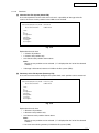
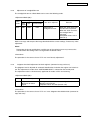
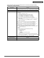
Turn the power ON while pressing the [4] and the [CLEAR] button simultaneously. Then the type
of the mounted HDD is checked and either of the following screens is displayed.
• When the security HDD is mounted
HDD Assist Mode
Current HDD type: ADI HDD
System Firmware Version : xxxx(x.x.x.x)
Update Mode
: 4c Mode
Select number (1-2) and press START key
1. Revert factory initial status HDD
2. Remove key
Fig. 3-7
45641001TH Rev.1
3-18 /
Oki Data CONFIDENTIAL
• When a normal HDD is mounted
HDD Assist Mode
Current HDD type: SATA HDD
System Firmware Version : xxxx(x.x.x.x)
Update Mode
: 4c Mode
Select number (1-2) and press START key
1. Revert factory initial status HDD
2. Remove key
Fig. 3-8
Remarks:
If the HDD type cannot be identified, “Unknown HDD” may appear on the screen.
Refer to & P. 5-54 “ [F106_1] ADI-HDD error: HDD type detection error”
Note:
When “SATA HDD” (normal HDD) is displayed, items 1 and 2 are not selectable.
If you select any of 1 and 2 and press the [START] button, the error message below
appears.
HDD Assist Mode
Current HDD type: SATA HDD
System Firmware Version : xxxx(x.x.x.x)
Update Mode
: 4c Mode
Select number (1-2) and press START key
=> 1. Revert factory initial status HDD
2. Remove key
Operation Failed.
Press SoftPower Key to Switch Off
Fig. 3-9
45641001TH Rev.1
3-19 /
Oki Data CONFIDENTIAL
3.10.3Functions
[A] 1. Revert factory initial status HDD
Select this to dispose of the ADI-HDD as well as the equipment.
When this item is selected, all data in the HDD are deleted and the HDD is reverted to its
initial status at the factory shipment.
This operation requires only a few seconds; however, you must create the partition in the
HDD in the 3C mode (Format HDD) and reinstall the HDD data in the 49 mode to make the
HDD reusable.
When “1” is selected and then [START] button is pressed, the menu below appears. To start,
press the [START] button.
HDD Assist Mode
Current HDD type: ADI HDD
System Firmware Version : xxxx(x.x.x.x)
Update Mode
: 4c Mode
Select number (1-2) and press START key
=> 1. Revert factory initial status HDD
2. Remove key
Confirmation Screen
Are you sure ???
Press START to continue
Press STOP to cancel
Fig. 3-10
When the operation is finished, the result appears on the menu.
HDD Assist Mode
Current HDD type: ADI HDD
System Firmware Version : xxxx(x.x.x.x)
Update Mode
: 4c Mode
Select number (1-2) and press START key
=> 1. Revert factory initial status HDD
2. Remove key
Data in the HDD has been complately erased.
Press SoftPower Key to Switch Off
Fig.5-1
Note:
If the equipment is started in the normal mode with this condition, an HDD mounting error
occurs.
45641001TH Rev.1
3-20 /
Oki Data CONFIDENTIAL
[B] 2. Remove Key
Select this to reuse the ADI-HDD as well as the equipment.
When this item is selected, all image data in the HDD are deleted.
This operation requires approx. 20 minutes since the partition must be rebuilt.
When “2” is selected and then [START] button is pressed, the menu below appears.
To start, press the [START] button.
HDD Assist Mode
Current HDD type: ADI HDD
System Firmware Version : xxxx(x.x.x.x)
Update Mode
: 4c Mode
Select number (1-2) and press START key
1. Revert factory initial status HDD
=> 2. Remove key
Confirmation Screen
Are you sure ???
Press START to continue
Press STOP to cancel
Fig. 3-11
When the operation is finished, the result appears on the menu.
HDD Assist Mode
Current HDD type: ADI HDD
System Firmware Version : xxxx(x.x.x.x)
Update Mode
: 4c Mode
Select number (1-2) and press START key
1. Revert factory initial status HDD
=> 2. Remove key
Data in the HDD has been erased.
Press SoftPower Key to Switch Off
Fig. 3-12
Note:
After this operation, the equipment becomes reusable without reinstalling the firmware.
45641001TH Rev.1
3-21 /
Oki Data CONFIDENTIAL
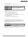
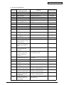
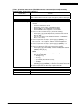
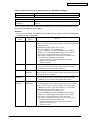
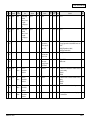
3.11 File System Recovery Mode (5C)
3.11.1Overview
This is a mode to check if there is any damage to the file system (HDD) and recover it if
necessary. Use this mode only in the following cases:.
• There is a possibility of damage to the file system (HDD).
• There is an apparent damage to the file system (HDD), requiring recovery or initialization.
This mode enables you to have the following functions:
• Check F/S: Checks the file system.
• Recovery F/S: Recovers the file system.
• Initialize HDD: Initializes partitions in the HDD.
• Initialize DB: Initializes database (LDAP DB/log DB/language DB).
• SMART Info: Displays the various information in the HDD.
• DISK Info: Displays the usage rate of HDD.
• HDD Utility: Initializes log files.
3.11.2
Operation procedure
[5][C]
[POWER]
[Digital key]
(Selection)
[START]
[Digital key]
(Selection)
[START]
(HDD formatting)
(DB formatting
such as log data)
[POWER] OFF/ON
(Exit)
Notes:
• Do not turn the main power switch OFF after you select a menu and processing has started
(during processing).
• After the processing is completed, a beep sounds 4 times and either “Completed” or “Failed”
appears on the screen.
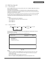
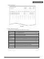
Turn ON the power while pressing the [5] and [CLEAR] button simultaneously. The following
screen is displayed.
File System(F/S) Recovery Mode -> Check F/S
Please Select Mode
>1. Check F/S
2. Recovery F/S
3. Initialize HDD
4. Initialize DB
5. SMART Info
6. DISK Info
7. HDD Utility
Fig. 3-13
Remark:
When the mode is started, “1. Check F/S” is selected by default.
(“>” is displayed on the left of the selected number.)
45641001TH Rev.1
3-22 /
Oki Data CONFIDENTIAL
3.11.3Functions
[A] Check of the File System (Check F/S)
In case that particular service calls occur or there is a possibility of damage to the file
system, the status of each partition in the HDD can be checked.
File System(F/S) Recovery Mode -> Check F/S
Please Select Partition
0: Main menu
1. ALL
2. /
3. /work
4. /registration
5. /backup
6. /imagedata
7. /storage
8. /encryption
Fig. 3-14
Explanation for each item
• 1: Checks all partitions.
• 2: Checks root partition only.
• 3-8: Checks each partition shown above.
Note:
More than one partition can be selected. (“>” is displayed on the left of the selected
number.)
• If damage is discovered, recover or initialize the file system (HDD).
[B] Recovery of the File System (Recovery F/S)
In case that an error occurs during the file system check, each partition can be recovered.
File System(F/S) Recovery Mode -> Recovery F/S
Please Select Partition
0: Main menu
1. ALL
2. /
3. /work
4. /registration
5. /backup
6. /imagedata
7. /storage
8. /encryption
Fig. 3-15
Explanation for each item
• 1: Recovers all partitions.
• 2: Recovers root partition only.
• 3-8: Recovers each partition shown above.
Note:
More than one partition can be selected. (“>” is displayed on the left of the selected
number.)
• If an error occurs during recovery, initialize the file system (HDD).
45641001TH Rev.1
3-23 /
Oki Data CONFIDENTIAL
[C] Initialize the File System (Initialize HDD)
In case that an error occurs during the file system check and the partition cannot be
recovered with the recovery, each partition can be initialized.
It is recommended to export the user information such as address book before performing
this function.
File System(F/S) Recovery Mode -> Initialize HDD
Please Select Partition
1. Except /
2. /work
3. /registration
4. /backup
5. /imagedata
6. /storage
7. /encryption
8. /TAT
Fig. 3-16
Explanation for each item
• 1: Initializes partitions other than root one and creates initial files.
• 2: Initializes a partition (/work) and creates an initial file.
• 3: Initializes a partition (/registration) and creates an initial file.
• 4: Initializes a partition (/backup) and creates an initial file.
• 5: Initializes a partition (/imagedata) and creates an initial file.
• 6: Initializes a partition (/storage) and creates an initial file.
• 7: Initializes a partition (/encryption) and creates an initial file.
• 8: Initializes a partition (/TAT) and creates an initial file.
Remark:
More than one partition can be selected. (“>” is displayed on the left of the selected
number.)
Notes:
• If [1. Except /] is selected, minimal data necessary for normal startup are
automatically recovered.
• If [1. Except /] is selected, log database is also initialized. Back up the data before
initializing if necessary.
45641001TH Rev.1
3-24 /
Oki Data CONFIDENTIAL
[D] Initialize the DB (Initialize DB)
In case that particular service calls occur or there is a possibility of damage to the
databases, each one can be initialized.
File System(F/S) Recovery Mode -> Initialize DB
Please Select Partition
0: Main menu
1. LDAP DB
2. Log DB(Job,Msg)
3. Language DB
Fig. 3-17
Explanation for each item
• 1: Initializes address book data and the user information database.
• 2: Initializes job log data and the message database.
• 3: Initializes the language database.
Notes:
The selected databases are initialized and recreated in the next normal startup.
[E] Displaying various data in the HDD (SMART Info)
Various data in the HDD can be displayed. (Data equivalent to the setting contents of 089065 are displayed.)
When this item is selected, data in the HDD embedded in the equipment are displayed. “---”
is displayed for the items not supported.
File System(F/S) Recovery Mode -> SMART Info
Please Select
1: PrevPage
Model : Hitachi xxxxxxxxxxx
ID NAME
01 Read Error Rate
02 Throughput Performance
03 Spin Up Time
.
.
.
2:NextPage
VALUE
0
0
15
.
.
.
0: Main menu
Serial : xxxxxxxxx
NAV Worst
100
100
100
100
253
253
.
.
.
.
.
.
Fig. 3-18
Remark:
• NAV: Normalized Attribute Value
Indicates the value of the specified HDD condition as compared to the
manufacturer’s optimum value.
• Worst: Worst Ever Normalized Attribute Value
Indicates the worst value of NAV permitted by the manufacturer.
Notes:
The values of NAV and Worst should be treated as a rough reference since their
basis may differ depending on the specification of HDD manufacturers.
45641001TH Rev.1
3-25 /
Oki Data CONFIDENTIAL
[F] Displaying usage rate of each partition (DISK Info)
The usage rate of each partition can be checked.
When this item is selected, the usage rate of each partition is displayed.
File System(F/S) Recovery Mode -> DISK Info
0: Main menu
Partition name
/
/work
/registration
/backup
/imagedata
/storage
/encryption
ALL(Mbyte)
FREE(Mbyte)
8737
5401
10326
9563
2861
3099
1036
949
24778
23343
25332
26873
--- encrypted partition ---
USE(%)
33.1%
2.3%
2.6%
3.3%
0.7%
0.7%
MT:OK
MT:OK
MT:OK
MT:OK
MT:OK
MT:OK
Fig. 3-19
Remark:
The disk information of a partition indicated as “Encrypted Partition” is not displayed
as it is encrypted.
[G] Initialization of log file (HDD Utility)
Normally it is not necessary to use this menu.
45641001TH Rev.1
3-26 /
Oki Data CONFIDENTIAL
3.12 SRAM Clear Mode (6C)
3.12.1
General description
This is a mode in which you can clear particular errors such as F800 or F900 without entering a
Service Technician password.
For example, when SYS-SRAM is in an abnormal status or needs replacement but service
technicians cannot log into the 3C mode, SRAM can be initialized by entering the SRAM clear
mode (6C) and selecting item 1 below.
The content of item 1 in this mode is the same as that of item 4 in the 3C mode (Clear SRAM).
Use this mode to clear the SRAM data when a particular error occurs or service technicians
cannot log in with their password and therefore cannot use the 3C mode.
Functions
• Sets the serial number of this equipment.
• Clears SRAM data when the 3C mode cannot be used.
• Clears F800 error.
• Clears F900 error.
3.12.2
Operation procedure
[6][C]
[Power]
[Digital Key]
(Select)
[START]
[STOP]
[START]
SRAM data
( clear
)
or
S/N Input
[Power] OFF
Cancel
Turn the power ON while pressing the [6] and the [CLEAR] button simultaneously. Then the
following screen is displayed.
Key in the desired item number and then press the [START] button.
SRAM Clear Mode
System Firmware Version : xxxx(x.x.x.x)
Update Mode
: 6c Mode
0. Set Serial Number
1. Clear SRAM
2. Reset Date and Time
3. SRAM Re-Initialize Support
Fig. 3-20
Notes:
• When “0” is keyed in and the [START] button is pressed, the menu to key in the serial
number appears. Key in the serial number of this equipment and then press [OK] to
determine the setting.
• Items 1 and 2 can be canceled while 0 and 3 cannot.
• When “3” is keyed in and the [START] button is pressed, the operation starts.
45641001TH Rev.1
3-27 /
Oki Data CONFIDENTIAL
3.12.3Functions
[A] 0. Set Serial Number
When replacing SYS-SRAM, select this to set the serial number of the equipment since it
must be done in advance of recovery from SRAM backup data.
• Clear SRAM first and then set the serial number in this mode.
• Recover from SRAM backup data after setting the serial number.
Refer to & P. 9-2 “9.1.4 Cloning procedure”
Select “0” and then press the [START] button. Then key in the serial number of this
equipment. The keyed in serial number appears on the menu.
SRAM Clear Mode
System Firmware Version : xxxx(x.x.x.x)
Update Mode
: 6c Mode
> 0. Set Serial Number
Serial Number Setting Complated.. xxxxxxxxxx
1. Clear SRAM
2. Reset Date and Time
3. SRAM Re-Initialize Support
Fig. 3-21
[B] 1. Clear SRAM
Select this to clear all SRAM data when replacing SYS-SRAM.
• Replace the SRAM board and then clear the SRAM data.
• After clearing the SRAM data, initialize SRAM following its replacement procedure.
Refer to & P. 6-22 “6.2.5 Precautions and procedure when replacing the SRAM board (for
the SYS board)”.
[C] 2. Reset Date and Time
Select this to clear an F800 error which occurred when the date and time were set as after
the end of the year 2037 or when the actual end of the year 2037 has come.
• After selecting this, start the equipment in the normal mode to reset the date and time.
[D] 3. SRAM Re-Initialize Support
When the SRAM board (for the SYS board) and the SYS board are replaced at the same
time, or an F900 error occurs, the machine information needs to be reset with this function.
After the resetting is completed, initialize SRAM following its replacement procedure.
& P. 6-22 “6.2.5 Precautions and procedure when replacing the SRAM board (for the SYS
board)”
45641001TH Rev.1
3-28 /
Oki Data CONFIDENTIAL
3.13 List print mode (9S)
3.13.1
Operation procedure
[1] Print out
[9][START]
[POWER]
(Code)
[Digital keys]
[START]
101: Adjustment mode (05)
Key in the first
102: Setting mode (08)
code to be printed
[START]
[Digital keys]
Key in the last
code to be printed
[START]
List starts to
be printed
[POWER]
OFF/ON
(Exit)
(Code)
106: Error history (Maximum 1000 items)
107: Error history (Latest 80 items)
108: Firmware update log (Maximum 200 items)
110: Power-ON/OFF log (Maximum 100 items)
111: Version list
114: Total counter list
[2] CSV output (USB)
[9][START]
[POWER]
Connect
USB
[Digital keys] [START] [Digital keys]
(Code)
[START]
201: Adjustment mode (05) Key in the first
Key in the last
code to be printed
code to be printed
202: Setting mode (08)
[START] Disconnect
List starts to
USB
be printed
[POWER]
OFF/ON
(Exit)
(Code)
206: Error history (Maximum 1000 items)
208: Firmware update log (Maximum 200 items)
210: Power-ON/OFF log (Maximum 100 items)
211: Version list
214: Total counter list
300: ALL CSV files
Notes:
Precautions when storing information into USB device
• When storing the setting information of the equipment into a USB device, be sure to obtain
permission from a user in advance.
• When storing the setting information of the equipment into a USB device, the information is
printed out in a CSV format. Handle and manage the information with extra care.
• Do not lose or leak the setting information of the equipment.
• Do not use the setting information of the equipment for purposes other than maintenance or
product services.
• Provide the information promptly if a user requires so.
• The buttons on the control panel keep blinking while data are being stored in the USB
device.
Do not disconnect the USB device while data are being stored.
Remarks:
In the USB storage procedure above, lists are stored in a CSV format. The names of the CSV
files are shown below.
201: ADJUSTMENT_LIST_serial_date and time(YYYYMMDDHHMMSS).csv
202: SETTING_LIST_serial_date and time(YYYYMMDDHHMMSS).csv
206: ERROR_LOG_serial_date and time(YYYYMMDDHHMMSS).csv
208: FW_UPGRADE_LOG_serial_date and time(YYYYMMDDHHMMSS).csv
210: POWER_ONOFF_LOG_serial_date and time(YYYYMMDDHHMMSS).csv
211: VERSION_LIST_serial_date and time(YYYYMMDDHHMMSS).csv
214: TOTAL_COUNTER_LIST_serial_date and time(YYYYMMDDHHMMSS).csv
45641001TH Rev.1
3-29 /
Oki Data CONFIDENTIAL
3.13.2
List Printing
Lists below are output in the list print mode.
List data are printed out or output in a CSV format by storing them in a USB device. Paper sizes
available for this printing are A4 or LT or larger. This section introduces a sample of each list.
To start the list print mode, turn the power on while pressing [9] + [START] button.
List code
Lists
Printout
CSV file output
Adjustment mode (05) data list
101
201
Setting mode (08) data list
102
202
Error history list
106 (Maximum 1000 items)
206 (Maximum 1000 items)
Error history list
107 (Latest 80 items)
-
Firmware upgrade log
108 (Maximum 200 items)
208 (Maximum 200 items)
Power ON/OFF log
110 (Maximum 100 items)
210 (Maximum 100 items)
Version list
111
211
Total counter list
114
214
Output all CSV files
-
300
Toner replacement log
812 (Maximum 1024 items)
912 (Maximum 1024 items)
• Adjustment mode (05)
05 ADJUSTMENT MODE
DATA LIST
20xx-xx-xx xx:xx
S/N: xxxxxxxxx
TOTAL:
9999999
OKI MBxxx
DF TOTAL:
9999999
CODE
DATA
CODE
DATA
CODE
DATA
CODE
DATA
2000
128
3860
88
4830
128
5920
128
Fig. 3-22
The selected adjustment codes and the current adjustment value for each code are output in a
list. See the following page for the adjustment code (05):
Refer to “Appendix” - “Adjustment Code (05).”
45641001TH Rev.1
3-30 /
Oki Data CONFIDENTIAL
• Setting mode (08)
08 SETTING MODE
DATA LIST
20xx-xx-xx xx:xx
S/N: xxxxxxxxx
TOTAL:
9999999
OKI MBxxx
DF TOTAL:
9999999
CODE
DATA
CODE
DATA
CODE
DATA
CODE
DATA
2010
2
2880
12
3040
0
3070
0
Fig. 3-23
The selected setting codes and the current setting value for each code are output in a list. See
the following page for the setting code (08):
Refer to “Appendix” - “Setting Code (08)”
45641001TH Rev.1
3-31 /
Oki Data CONFIDENTIAL
• Error history
ERROR HISTORY LIST
20xx-xx-xx xx:xx
CODE
F110
F110
F110
F110
F110
EAD0
E860
E731
E090
E870
E724
COUNTER
00000000
00000000
00000000
00000000
00000000
00000000
00000000
00000000
00000000
00000000
00000000
DATE
xxxx-xx-xx
xxxx-xx-xx
xxxx-xx-xx
xxxx-xx-xx
xxxx-xx-xx
xxxx-xx-xx
xxxx-xx-xx
xxxx-xx-xx
xxxx-xx-xx
xxxx-xx-xx
xxxx-xx-xx
TIME
xx:xx:xx
xx:xx:xx
xx:xx:xx
xx:xx:xx
xx:xx:xx
xx:xx:xx
xx:xx:xx
xx:xx:xx
xx:xx:xx
xx:xx:xx
xx:xx:xx
ZOOM_XY
000 000
000 000
000 000
000 000
000 000
000 000
000 000
000 000
000 000
000 000
000 000
S/N: xxxxxxxxx
TOTAL:
9999999
OKI MBxxx
DF TOTAL:
9999999
ABCD EFHI JLOP Q R
0000_0000_0000_0_0000000000
0000_0000_0000_0_0000000000
0000_0000_0000_0_0000000000
0000_0000_0000_0_0000000000
0000_0000_0000_0_0000000000
0000_0000_0000_0_0000000000
0000_0000_0000_0_0000000000
0000_0000_0000_0_0000000000
0000_0000_0000_0_0000000000
0000_0000_0000_0_0000000000
0000_0000_0000_0_0000000000
Fig. 3-24
The error history is output. See the following page for the parameters for each error:
& P. 5-17 “5.2.4 Printer function error”
45641001TH Rev.1
3-32 /
Oki Data CONFIDENTIAL
• Firmware update log
FW UPGRADE LOG
xx-xx-xx xx:xx
USER ROM/VERSION DATE
TOTAL
S/N: xxxxxxxxx
TOTAL:
9999999
OKI MBxxx
DF TOTAL:
9999999
COPY(B) COPY(2) COPY(C) PRINT(B) PRINT(2) PRINT(C) LIST
Service Txxxxxxx-xxxx 20xx-xx-xx 99999999 99999999
Service Txxxxxxx-xxxx 20xx-xx-xx 99999999 99999999
Service Txxxxxxx-xxxx 20xx-xx-xx 99999999 99999999
0
0
0
0 99999999
0 99999999
0 99999999
0
0
0
FAX
STATUS
0 99999999 99999999 OK
0 99999999 99999999 OK
0 99999999 99999999 OK
Fig. 3-25
Firmware update logs are output.
- Only the versions of ROMs updated with USB device are output.
Item
Content
USER
User who updated firmware
ROM/VERSION
Version of firmware
DATE
Date that firmware was updated
TOTAL
Total counter data when firmware was updated
COPY (B)
Copier counter data (black) when firmware was updated
COPY (2)
Since this function is unavailable for the machine, “0” always appears.
COPY (C)
Since this function is unavailable for the machine, “0” always appears.
PRINT (B)
Printer counter data (black) when firmware was updated
PRINT (2)
Since this function is unavailable for the machine, “0” always appears.
PRINT (C)
Since this function is unavailable for the machine, “0” always appears.
LIST
List print counter data when firmware was updated
FAX
Fax print counter data when firmware was updated
STATUS
Result of update
45641001TH Rev.1
3-33 /
Oki Data CONFIDENTIAL
• Power-ON/OFF log
POWER ON_OFF LOG
20xx-xx-xx xx:xx
DATE
xxxx-xx-xx
xxxx-xx-xx
xxxx-xx-xx
xxxx-xx-xx
xxxx-xx-xx
xxxx-xx-xx
xxxx-xx-xx
xxxx-xx-xx
xxxx-xx-xx
xxxx-xx-xx
TIME
xx:xx:xx
xx:xx:xx
xx:xx:xx
xx:xx:xx
xx:xx:xx
xx:xx:xx
xx:xx:xx
xx:xx:xx
xx:xx:xx
xx:xx:xx
FUNCTION
ON
OFF
ON
OFF
ON
OFF
ON
OFF
RMT_OFF
OFF
TOTAL
99999999
99999999
99999999
99999999
99999999
99999999
99999999
99999999
99999999
99999999
S/N: xxxxxxxxx
TOTAL:
9999999
OKI MBxxx
DF TOTAL:
9999999
DATE
xxxx-xx-xx
xxxx-xx-xx
xxxx-xx-xx
xxxx-xx-xx
xxxx-xx-xx
TIME
xx:xx:xx
xx:xx:xx
xx:xx:xx
xx:xx:xx
xx:xx:xx
FUNCTION
ON
OFF
ON
OFF
RMT_OFF
TOTAL
99999999
99999999
99999999
99999999
99999999
Fig. 3-26
Power ON/OFF logs are output.
- Note that cases that the power was turned OFF with the main switch (not with the [ON/OFF]
button on the control panel) will not be displayed.
Item
Content
DATE
Date that the power was turned ON or OFF
TIME
Time that the power was turned ON or OFF
FUNCTION
Whether the power was turned ON or OFF, or if it was turned
ON or OFF with a remote reset function
TOTAL
Total counter data when the power was turned OFF and then back ON
45641001TH Rev.1
3-34 /
Oki Data CONFIDENTIAL
• Version list
VERSION LIST
S/N: xxxxxxxxx
TOTAL:
9999999
OKI MBxxx
DF TOTAL:
9999999
’xx-xx-xx xx:xx
SYSTEM FIRMWARE ROM VERSION
: Txxxxxxxxxxx
SYSTEM FIRMWARE INTERNAL ROM VERSION
: Vxxxx.xxx
PRINTER ROM VERSION
: xx.xx.xx
PRINTER LOADER ROM VERSION
: xx.xx.xx
PRINTER OPTION TRAY ROM VERSION (TRAY2)
: xx.xx.xx
PRINTER OPTION TRAY ROM VERSION (TRAY3)
: xx.xx.xx
PRINTER OPTION TRAY ROM VERSION (TRAY4)
: xx.xx.xx
SCANNER ROM VERSION
: xx.xx.xx
SCANNER LOADER ROM VERSION
: xx.xx.xx
SCANNER RECOVERY FW ROM VERSION
: xx.xx.xx
FINISHER STACKER ROM VERSION
: xx.xx.xx
FAX BOARD FIRMWARE ROM VERSION
: Fxxx-xxx
SYSTEM FIRMWARE INTERNAL OS VERSION
: xxxx-xx
HDD DATA VERSION
: Txxxxxxxxxxx
SYSTEM FIRMWARE OS VERSION
: Txxxxxxxxxxx
LANGUAGE VERSION
English(US)
: xxx.xxx xxx xxx xx xx:xx:xx xxxx
CAPACITY OF HDD
DEVICE INFORMATION OF HDD
SERIAL NUMBER OF HDD
MEMORY SIZE
INSTALLED ELK NAME
: xx.x GB
: xxx xxxxxxx-xxxxxx
: xx-xxxxxxxxxxxx
: xxxx MB / xxxx MB
: IPSec enabler
Meta scan enabler
Fig. 3-27
The list of versions is output.
Notes:
Some of the characters in the fonts that are used to print the version list are not supported.
As a result, the language names under LANGUAGE VERSION may not be printed correctly
when printing the version list.
45641001TH Rev.1
3-35 /
Oki Data CONFIDENTIAL
• Total counter list
TOTAL COUNTER LIST
’xx-xx-xx xx:xx
S/N: xxxxxxxxx
TOTAL:
9999999
OKI MBxxx
DF TOTAL:
9999999
PRINT COUNTER
COPY
FAX
PRINTER
TOTAL
LIST
SMALL xxxxxxxxx xxxxxxxxx xxxxxxxxx xxxxxxxxx xxxxxxxxx
LARGE xxxxxxxxx xxxxxxxxx xxxxxxxxx xxxxxxxxx xxxxxxxxx
TOTAL xxxxxxxxx xxxxxxxxx xxxxxxxxx xxxxxxxxx xxxxxxxxx
SCAN COUNTER
TOTAL
COPY
FAX
COPY
FAX
NETWORK
TOTAL
FULL COLOR
0
0
xxxxxxxxx
xxxxxxxxx
BLACK
xxxxxxxxx
xxxxxxxxx
xxxxxxxxx
xxxxxxxxx
TOTAL
xxxxxxxxx
xxxxxxxxx
xxxxxxxxx
xxxxxxxxx
SMALL
LARGE
TOTAL
BLACK
FULL COLOR
0 xxxxxxxxx
0 xxxxxxxxx
0 xxxxxxxxx
TOTAL
xxxxxxxxx
xxxxxxxxx
xxxxxxxxx
BLACK
FULL COLOR
0 xxxxxxxxx
0 xxxxxxxxx
0 xxxxxxxxx
TOTAL
xxxxxxxxx
xxxxxxxxx
xxxxxxxxx
BLACK
FULL COLOR
xxxxxxxxx xxxxxxxxx
xxxxxxxxx xxxxxxxxx
xxxxxxxxx xxxxxxxxx
TOTAL
xxxxxxxxx
xxxxxxxxx
xxxxxxxxx
SMALL
LARGE
TOTAL
NETWORK
SMALL
LARGE
TOTAL
CALIBRATION COUNTER : xx
Fig. 3-28
The list of total counter is output.
45641001TH Rev.1
3-36 /
Oki Data CONFIDENTIAL
4.SETTING / ADJUSTMENT
4.1 Image Related Adjustment
4.1.1
Adjustment Order
This chapter mainly explains the procedures for image related adjustment. In the following
diagram, the solid lines with arrow lead to essential adjustments, while the dotted lines lead to
adjustments to be performed if necessary.
Parts to be replaced
Drum unit
Transfer blet unit
Order
1
2
4.1.3 Image dimensional adjustment
Item
Code in 05 mode
Image dimensional adjustment
7000
in the copy/printer/fax function
7001 (*2)
Item to be adjusted
4.2.1 Automatic gamma adjustment
Code in 05 mode
7165 (*1)
Adjust the image quality if necessay.
END
Chapter 4.2, 4.3, 4.4, 4.5
*1: Use [10] + [FAX] test pattern.
*2: Adjustment can be done only for enlarging image.
Fig. 4-1
45641001TH Rev.1
4-1 /
Oki Data CONFIDENTIAL
4.1.2
Image Dimensional Adjustment
There are several adjustment items in the image dimensional adjustment, as listed below.
Item to be adjusted
Code in mode 05
Image dimensional
Reproduction ratio adjustment of primary 7000
adjustment in the copy/ scanning direction (PPC)
printer/fax function
Reproduction ratio adjustment of primary 7001*1
scanning direction (PRT/FAX)
*1: Adjustment can be done only for enlarging image.
[Procedure to key in adjustment values]
In accordance with the procedure described below, make adjustment of each adjustment item
so that the measured values obtained from test copies satisfy the specification. By pressing the
[FAX] button, immediately after starting the Adjustment Mode (05), single-sided test copying can
be performed (normal copy mode).
<Operation keys>
<Display>
100%
0
A
A4
TEST MODE
5
POWER
1
Digital keys : Key in codes.
Code No.
100%
START
A4
YYY
Digital keys : Key in adjustment
values.
( CLEAR Use to make corrections)
Value ZZZ is stored
OK
replacing values YYY.
or
INTERRUPT
FAX
START
XXX
TEST MODE
Test copy
ZZZ
Current adjustment value
100%
A
A4
A
A4
A
A4
Adjustment value newly keyed in.
(If no entering, YYY is displayed.)
TEST MODE
100%
Wait Warming Up
If the test copy does not
satisfy the specified values,
return to step 1 and
repeat the adjustment
procedure.
100%
COPYING
Power OFF/ON : Exit the Adjustment Mode.
Fig.6-1
45641001TH Rev.1
4-2 /
Oki Data CONFIDENTIAL
4.1.3
Image dimensional adjustment in the copy/printer/fax function
[1] Reproduction ratio adjustment of primary scanning direction
The reproduction ratio in the primary scanning direction of the printed image can be
adjusted as follows:
<Adjustment Mode (05)>
Code
Function
Remarks
7000
PPC
The larger the value is, the larger the reproduction ratio in the
primary scanning direction becomes.
(0.1%/step)
Acceptable values: 0 to 255 (Default: 128)
7001
PRT/FAX
The larger the value is, the larger the reproduction ratio in the
primary scanning direction becomes.
(0.1%/step)
Acceptable values: 128 to 255 (Default: 128)
Make a test copy and compare the image obtained with the current settings; if necessary,
make adjustments according to the following procedure:
Notes:
• Since the reproduction ratio may vary due to expansion and contraction of the paper
immediately after the image is printed out, it is recommended to measure its dimension
after at least 3 minutes have passed.
• This adjustment may cause image troubles such as moire, disappearance or breaking
of thin lines on the printed image. Therefore check if there is no such image trouble
while you are performing the adjustment.
<Procedure>
(1) While pressing [0] and [5] simultaneously, turn the power ON.
(2) Key in a code and press the [START] button.
(3) Key in the adjustment value. (To correct a value, press the [CLEAR] button.)
(4) Press the [OK] or [INTERRUPT] button to store the value. -> The equipment goes back
to the ready state.
(5) Make a test copy and check the image copied. To check the printed image, turn off the
power and then back on, and then print the image. If the image is not in the desired
reproduction ratio, repeat steps (2) to (4).
45641001TH Rev.1
4-3 /
Oki Data CONFIDENTIAL
4.2 Image Quality Adjustment (Copying Function)
4.2.1
Automatic gamma adjustment
When the reproduction of gradation is not appropriate, the gradation reproducibility can be
corrected by performing this automatic gamma adjustment. In case the gradation reproduction
of the image checked is not satisfactory, make this adjustment as described below at parts
replacement.
When unpacking or any of the following parts has been replaced, be sure to make this adjustment:
• Drum unit
• Transfer belt unit
• SRAM board (SYS board)
• PU board
• HDD
Notes:
Be sure that this adjustment be made after performing the image adjustment in & P. 4-2 “4.1.2
Image Dimensional Adjustment”.
<Procedure>
(1) While pressing [0] and [5] simultaneously, turn the power ON. → Adjustment Mode
(2) Select the A4/LT drawer. Key in the pattern number and press the [FAX] button to output a “Patch
chart for gamma adjustment”.
<Adjustment Mode (05)>
Pattern No.
10
Pattern No.
Black
Remark
When performing code 05-7165
Paper type
All paper types
(3) Place the patch chart for adjustment printed in step (2) face down on the original glass.
Place the chart aligning its side with a black square against the original scale.
(4) Key in a code and press the [START] button.
→ The scanner reads the chart automatically and performs automatic gamma adjustment
calculation (approx.30 sec.).
<Adjustment Mode (05)>
Code
Item to be adjusted
7165
Automatic gamma
adjustment
Contents
When the reproduction of gradation is not appropriate, the
gradation reproducibility can be corrected by performing
this automatic gamma adjustment. The result of 7165 is
applied to all paper types.
(5) When the adjustment has finished normally, press the [OK] button to have the adjustment
results reflected.
(To cancel the reflection of adjustment results, press the [CANCEL] button.)
In the case of an abnormal ending, “ADJUSTMENT ERROR” is shown.
Press the [CANCEL] button to clear the error display. When it is cleared, the control panel
display will return to the ready state. Then, check if the patch chart on the original glass is
placed in the wrong direction or if it is placed inclined on the original glass, and then repeat
step (3) and afterward.
45641001TH Rev.1
4-4 /
Oki Data CONFIDENTIAL
4.2.2
Density adjustment
The center density and the density variation controlled by density adjustment keys can be
adjusted as follows.
<Adjustment Mode (05)>
Color
mode
Black
Original mode
Text/
Photo
Text
Photo
Custom
Mode
Item to be adjusted
Remarks
7114
7115
7116
7134
Manual density mode
center value
7123
7124
7125
7137
Automatic density
mode
The larger the value is, the
darker the image becomes.
Acceptable values:
0 to 255 (Default: 128)
7117
7118
7119
7135
Manual density mode
lightness value
The larger the value is, the
lighter the image becomes.
Acceptable values:
0 to 255 (Default: 20)
7120
7121
7122
7136
Manual density mode
darkness value
The larger the value is, the
darker the image becomes.
Acceptable values:
0 to 255 (Default: 20)
Make a test copy and compare the image obtained with the current settings; if necessary, make
adjustments according to the following procedure.
Notes:
Be sure that this adjustment is made after performing & P. 4-4 “4.2.1 Automatic gamma
adjustment”.
<Procedure>
(1) While pressing [0] and [5] simultaneously, turn the power ON.
(2) Key in a code and press the [START] button.
(3) Key in an adjustment value.
(To correct the value once keyed in, press the [CLEAR] button.)
(4) Press the [OK] or [INTERRUPT] button to store the value. → The equipment goes back to
the ready state.
(5) Press the [FAX] button and then press the [START] button to make a test copy.
If the original mode is Custom, restart the equipment and check if the desired image quality
is attained.
(6) If the desired image quality has not been attained, repeat step (2) to (5).
If the original mode is Custom, repeat step (1) to (5).
45641001TH Rev.1
4-5 /
Oki Data CONFIDENTIAL
4.2.3
Gamma balance adjustment
The density adjustment at the Black Mode is performed by selecting its density area from the
following: low density, medium density and high density.
<Adjustment Mode (05)>
Original mode
Color
mode
Text/
Photo
Black
Text
Photo
Custom
Mode
Item to be adjusted
7190-0 7191-0 7192-0 7276-0 Low density
7190-1 7191-1 7192-1 7276-1 Medium density
7190-2 7191-2 7192-2 7276-2 High density
Remarks
The larger the value is, the
density of the item to be
adjusted becomes darker.
Acceptable values:
0 to 255 (Default: 128)
Make a test copy and compare the image obtained with the current settings; if necessary, make
adjustments according to the following procedure.
Notes:
Be sure that this adjustment is made after performing & P. 4-4 “4.2.1 Automatic gamma
adjustment”.
<Procedure>
(1) While pressing [0] and [5] simultaneously, turn the power ON.
(2) Key in the code of the mode to be adjusted (original mode) and press the [START] button.
(3) Select the density area to be adjusted with digital keys (0, 1 or 2), and press the [START]
button.
0: Low density
1: Medium density
2: High density
(4) Key in an adjustment value. (To correct the value once keyed in, press the [CLEAR] button.)
(5) Press the [OK] or [INTERRUPT] button to store the value in memory.
→ The equipment goes back to the ready state.
(6) For resetting the value, repeat step (2) to (5).
(7) Press the [FAX] button and then press the [START] button to make a test copy.
If the original mode is Custom, restart the equipment and check if the desired image quality
is attained.
(8) If the desired image quality has not been attained, repeat step (2) to (7).
If the original mode is Custom, repeat step (1) to (7).
45641001TH Rev.1
4-6 /
Oki Data CONFIDENTIAL
4.2.4
Background adjustment
The density of the background can be adjusted as follows.
<Adjustment Mode (05)>
Color
mode
Black
Original mode
Text/
Photo
Text
Photo
Custom
Mode
7100
7101
7102
7106
Remarks
The larger the value is, the darker the background
becomes.
Acceptable values: 0 to 255 (Default: 128)
Make a test copy and compare the image obtained with the current settings; if necessary, make
adjustment using the following procedure.
<Procedure>
The procedure is the same as that of & P. 4-5 “4.2.2 Density adjustment”.
4.2.5
Judgment threshold for ACS (common for copy and scan)
Judgment levels for automatically identifying whether an original is color or black are adjusted.
This adjustment is for judgment levels when “Auto Color” is selected as a color mode. The same
adjustment value is simultaneously applied to all cases of originals on the original glass for
copier functions and network scanning functions, and those placed on the RADF.
<Adjustment Mode (05)>
Code
7630
Item to be adjusted
Judgment threshold for
ACS
Contents
The larger the value is, the more an original tends to be
judged as black . The smaller value is, the more it tends to
be judged as color.
Acceptable values: 0 to 255 (Default: 70)
Make a test copy and compare the image obtained with the current settings; if necessary and
make adjustment.
<Procedure>
(1) While pressing [0] and [5] simultaneously, turn the power ON.
(2) Key in a code and press the [START] button.
(3) Key in a sub-code and press the [START] button.
(4) Key in an adjustment value.
(To correct a value once keyed in, press the [CLEAR] button.)
(5) Press the [OK] or [INTERRUPT] button to store the value. → The equipment goes back to
the ready state.
(6) Turn the power OFF and back ON in the normal mode, and then make a copy.
(7) If the desired image quality has not been attained, repeat step (1) to (6).
45641001TH Rev.1
4-7 /
Oki Data CONFIDENTIAL
4.2.6
Sharpness adjustment
If you want to make copy images look softer or sharper, perform the following adjustment. The
adjustment can be made for each of the original modes independently.
<Adjustment Mode (05)>
Code
Color mode
7056
Black
Original mode
Text/Photo
7057
Text
7058
Photo
7249
Custom mode
Contents
The larger the value is, the sharper the image
becomes; while the smaller the value is, the softer
the image becomes.
The smaller the value is, the less moire tends to
appear.
Acceptable values: 0 to 255 (Default: 128)
Make a test copy and compare the image obtained with the current settings; if necessary, make
adjustment.
Notes:
You have to make adjustment by balancing between moire and sharpness.
<Procedure>
The procedure is the same as that of & P. 4-5 “4.2.2 Density adjustment”.
4.2.7
Setting range correction
The values of the background peak/text peak in the range correction at the Black Mode can be
switched to “varied” or “fixed” in the following codes.
If they are fixed, the range correction is performed with standard values.
The values of the background peak affects the reproduction of the background density, and the
values of the text peak affects that of the text density.
<Adjustment Mode (05)>
Color
mode
Black
Original mode
Item to be adjusted
Text/
Photo
Text
User Custom
7283
7284
7236
Auto density mode
7286
7287
7237
Manual density mode
Remarks
0: Background peak / fixed
1: Background peak / varied
(Default: 1)
Make a test copy and compare the image obtained with the current settings; if necessary, make
adjustment.
<Procedure>
The procedure is the same as that of & P. 4-5 “4.2.2 Density adjustment”.
45641001TH Rev.1
4-8 /
Oki Data CONFIDENTIAL
4.2.8
Adjustment of smudged/faint text
The smudge/faint text at a Black Mode can be set at the following codes.
<Adjustment Mode (05)>
Color
mode
Black
Original mode
Text/
Photo
Text
Custom mode
7097
7098
7252
Item to be adjusted
Adjustment of
smudged/ faint text
Remarks
When the value decreases,
the faint text is improved.
When the value increases,
the smudged text is
improved.
Acceptable values: 0 to 4
(Default: 2)
Make a test copy and compare the image obtained with the current settings; if necessary, make
adjustment.
Notes:
Remember the image specifications and life span of the replacing parts may not meet the
standard when the setting value is changed from the default value.
<Procedure>
The procedure is the same as that of & P. 4-5 “4.2.2 Density adjustment”.
4.2.9
Judgment threshold adjustment for blank originals (common for copy and scan)
The judgment level is adjusted for automatic identification of whether the original set is blank or
not. This adjustment is made when “OMIT BLANK PAGE” is selected on the control panel.
The adjustment value is simultaneously applied to all modes at PPC and scanning.
<Adjustment Mode (05)>
Code
7618
Item to be adjusted
Judgment threshold
adjustment for blank
original
Contents
The larger the value is, the more an original tends to be
judged as a bank sheet.
Acceptable values: 0 to 255 (Default: 128)
<Procedure>
The procedure is the same as that of & P. 4-7 “4.2.5 Judgment threshold for ACS (common for
copy and scan)”.
45641001TH Rev.1
4-9 /
Oki Data CONFIDENTIAL
4.2.10
Background offsetting adjustment for RADF (common for copy, scan and fax)
The background level for scanning originals with the RADF is adjusted when the background
fogging at the scanning of a manually-set original and an original used with the RADF is
different. This is to adjust the level of the background image removed when the scanning of the
originals with the RADF is performed.
<Adjustment Mode (05)>
Color mode
Code
Color
7026
Black
7025
Remarks
The larger the value is, the darker the background density
becomes.
Acceptable values: 0 to 255 (Default: 128)
<Procedure>
The procedure is the same as that of & P. 4-5 “4.2.2 Density adjustment”.
45641001TH Rev.1
4-10 /
Oki Data CONFIDENTIAL
4.3 Image Quality Adjustment (Printing Function)
4.3.1
Gamma balance adjustment (Black Mode)
The gamma balance is adjusted by adjusting the density at the Black Mode. The adjustment is
performed by selecting its density area from the following: low density, medium density, and high
density.
When “Black” (600 dpi) is set for the color mode and “Auto” is selected for the halftone setting,
the gamma balance can be adjusted in each area of Text, Graphics and Image.
<Adjustment Mode (05)>
Color
mode
Smooth Detail Smooth Detail Smooth Detail
(PS)
(PS)
(PCL)
(PCL)
(XPS)
Remarks
(XPS)
Black
(600dpi)
7315-0 7316-0 7317-0 7318-0 7319-0 7320-0 The larger the value is, the
7315-1 7316-1 7317-1 7318-1 7319-1 7320-1 density of the item to be
adjusted becomes darker.
7315-2 7316-2 7317-2 7318-2 7319-2 7320-2 Acceptable values: 0 to 255
(Default: 128)
Black
(1200dpi)
7309-0 7310-0
−
−
−
−
7309-1 7310-1
−
−
−
−
7309-2 7310-2
−
−
−
−
Auto (PS)
Color
mode
Black
(600dpi)
Text
Graphics
The larger the value is, the
density of the item to be
adjusted becomes darker.
Acceptable values: 0 to 255
(Default: 128)
Auto (XPS)
Image
Text
Graphics
Image
Remarks
7360-0 7361-0 7362-0 7366-0 7367-0 7368-0 The larger the value is, the
7360-1 7361-1 7362-1 7366-1 7367-1 7368-1 density of the item to be
adjusted becomes darker.
7360-2 7361-2 7362-2 7366-2 7367-2 7368-2 Acceptable values: 0 to 255
(Default: 128)
Notes:
• Be sure that this adjustment is made after performing & P. 4-4 “4.2.1 Automatic gamma
adjustment”.
• Changing the adjustment setting influences the adjacent density area slightly.
E.g.:When the value of the medium density is larger, the adjacent areas in the low density
and high density range will become slightly darker.
<Procedure>
(1) While pressing [0] and [5] simultaneously, turn the power ON.
(2) Key in the codes to be adjusted (language and screen) and press the [START] button.
(3) Key in the value corresponding to the density area to be adjusted (0, 1 or 2) and press the
[START] button.
0: Low density 1: Medium density 2: High density/Highest density
(4) Key in the adjustment value. (To correct the value once keyed in, press the [CLEAR] button.)
(5) Press the [OK] or [INTERRUPT] button to store the value in memory. → The equipment
goes back to the ready state.
(6) For resetting the value, repeat step (2) to (5).
(7) Let the equipment restart and perform the printing job.
(8) If the image density has not been attained, repeat step (1) to (7)
45641001TH Rev.1
4-11 /
Oki Data CONFIDENTIAL
4.3.2
Upper limit value in the Toner Saving Mode
The upper limit value of the density when “Toner save” is selected in the Custom tab of the
printer driver can be adjusted.
<Adjustment Mode (05)>
Color
Black
mode
PS
PCL
XPS
7307-0 7307-1 7307-2
1200dpi
Remarks
7302
The smaller the value is, the lighter the density of
image becomes.
Acceptable values: 0 to 255 (Default: 176)
<Procedure>
The procedure is the same as that of & P. 4-11 “4.3.1 Gamma balance adjustment (Black
Mode)”.
4.3.3
Thin line width lower limit adjustment
<Adjustment Mode (05)>
Code
Remarks
8240 (600dpi)
Sets the lower limit value of the thin line width when “Distinguish Thin Lines”
is
selected in the screen selecting menu of the printer driver.
8241 (1200dpi)
The larger the value is, the thicker (darker) the thin line becomes.
Acceptable values: 1 to 9 (Default: 1 for 8240 / 4 for 8241)
<Procedure>
(1) While pressing [0] and [5] simultaneously, turn the power ON.
(2) Key in the codes to be adjusted and press the [START] button.
(3) Key in the adjustment value. (To correct the value once keyed in, press the [CLEAR] button.)
(4) Press the [OK] or [INTERRUPT] button to store the value in memory. → The equipment
goes back to the ready state.
(5) For resetting the value, repeat step (2) to (4).
(6) Let the equipment restart and perform the printing job.
(7) If the desired image has not been attained, repeat step (1) to (6).
45641001TH Rev.1
4-12 /
Oki Data CONFIDENTIAL
4.3.4
Density adjustment of graphic lines (1200 dpi)
This adjustment is available regardless of whether “Distinguish Thin Lines” of the printer driver is
selected or not.
<Adjustment Mode (05)>
Color mode
Black
Code
8242-0
Remarks
The density of the line in Black in the line density range specified
by “05-8243-0” or “05-8243-1” can be adjusted.
The larger the value is, the darker the line density becomes.
Acceptable value: 0 to 5 (Default: 4)
Color mode
Black
Code
8243-0
Remarks
The effective range (lower limit) of the density
adjustment for the line in Black can be set.
Acceptable value: 0 to 255 (Default: 1)
8243-1
The effective range (upper limit) of the density
adjustment for the line in Black can be set.
The density
range selected
in the upper
and lower limit
is adjusted with
05-8242-0.
Acceptable value: 0 to 255 (Default: 200)
Notes:
Be sure to set the values of the upper and lower limit properly so that they are not set in
reverse.
<Procedure>
The procedure is the same as that of & P. 4-11 “4.3.1 Gamma balance adjustment (Black
Mode)”.
45641001TH Rev.1
4-13 /
Oki Data CONFIDENTIAL
4.4 Image Quality Adjustment (Scanning Function)
4.4.1
Gamma balance adjustment
The gamma balance at the Black Mode is adjusted by adjusting the density. The adjustment is
performed by selecting its density area from the following: low density, medium density and high
density.
<Adjustment Mode (05)>
Black
Original mode
Gray
Scale
Item to be
adjusted
Text/
Photo
Text
Photo
Custom
mode
7485-0
7486-0
7487-0
7480-0
7488-0 Low density
7485-1
7486-1
7487-1
7480-1
7488-1 Medium
density
7485-2
7486-2
7487-2
7480-2
7488-2 High density
Remarks
The larger the value is, the
density of the item to be
adjusted becomes darker.
Acceptable values: 0 to 255
(Default: 128)
<Procedure>
(1) While pressing [0] and [5] simultaneously, turn the power ON.
(2) Key in the code corresponding to the desired original mode and press the [START] button.
(3) Key in the value corresponding to the density area to be adjusted (0, 1 or 2) and press the
[START] button.
0: Low density (L), 1: Medium density (M), 2: High density (H)
(4) Key in the adjustment value. (To correct the value once keyed in, press the [CLEAR] button.)
(5) Press the [OK] or [INTERRUPT] button to store the value in memory.
→ The equipment goes back to the ready state.
(6) For resetting the value, repeat step (2) to (5).
(7) Let the equipment restart and perform the scanning job.
(8) If the desired image has not been attained, repeat step (1) to (7).
45641001TH Rev.1
4-14 /
Oki Data CONFIDENTIAL
4.4.2
Density adjustment
Adjusts the center density.
<Adjustment Mode (05)>
Color
Mode
Color
Original mode
Text/
Photo
Text
Photo
Custom
mode
8339
8340
8341
8380
Item to be
adjusted
Remarks
Manual
The larger the value is, the
density center darker the image becomes.
value
Acceptable values: 0 to 255
(Default: 128)
<Adjustment Mode (05)>
Original mode
Gray
Mode
Text/
Photo
Text
Black
7444
7445
7446
7475
7447
7456
7457
7458
7478
7459
Item to be
adjusted
Custom Scale
Photo
mode
Remarks
Manual
The larger the value is, the
density center darker the image becomes.
value
Acceptable values: 0 to 255
(Default: 128)
Automatic
density
<Procedure>
(1) While pressing [0] and [5] simultaneously, turn the power ON.
(2) Key in a code and press the [START] button.
(3) Key in an adjustment value (acceptable values: 0 to 255).
(To correct a value once keyed in, press the [CLEAR] button.)
(4) Press the [OK] or [INTERRUPT] button to store the value in memory.
→ The equipment goes back to the ready state.
(5) Let the equipment restart and perform the scanning.
(6) If the desired image quality has not been attained, repeat step (1) to (5).
45641001TH Rev.1
4-15 /
Oki Data CONFIDENTIAL
4.4.3
Background adjustment (Color Mode)
The adjustment level of background center value is adjusted. The control value of background
adjustment button is automatically adjusted to the same level as the adjusted center value.
For example, when the control value of background adjustment key ranges from 0 to 6, the
background center value (-2 to +2) is used to be the range from 6 to 14 accordingly.
Before adjustment
+2
+1
0
-1
-2
0 1 2 3 4 5 6 7 8 9 10 11 12 13 14 15 16 17
+2
After adjustment
+1
0
-1
-2
Fig 6-2
<Adjustment Mode (05)>
Code
Original mode
8309
Text/Photo
8310
Text
8311
Photo
8370
Custom mode
Remarks
The smaller the value is, the background becomes lighter.
Acceptable values: 0 to 255 (Default: 128)
<Procedure>
(1) While pressing [0] and [5] simultaneously, turn the power ON.
(2) Key in the codes and press the [START] button.
(3) Key in the adjustment values. Acceptable values: 0 to 255. (To correct the value once keyed
in, press the [CLEAR] button.)
(4) Press the [OK] or [INTERRUPT] button to store the value in memory.
→ The equipment goes back to the ready state.
(5) Let the equipment restart and perform the scanning job.
(6) If the desired image has not been attained, repeat step (1) to (5).
4.4.4
Background adjustment (Black/Grayscale)
The density of background can be adjusted as follows.
<Adjustment Mode (05)>
Code
7436
Color mode
Black
Original mode
Text/Photo
7437
Text
7438
Photo
7441
Custom mode
7439
Grayscale
Remarks
The smaller the value is, the background
becomes lighter.
Acceptable values: 0 to 255 (Default: 128)
−
<Procedure>
The procedure is the same as that of & P. 4-15 “4.4.2 Density adjustment”.
45641001TH Rev.1
4-16 /
Oki Data CONFIDENTIAL
4.4.5
Judgment threshold for ACS (common for copy and network scan)
The judgment level is adjusted for the automatic identification of whether the original set on the
glass is black or color. Namely, this is to adjust the judgment level used when “Auto Color” is
selected at color modes. The same adjustment value is simultaneously applied to all cases of
originals on the original glass for copier functions and network scanning functions, and those
placed on the RADF.
<Adjustment Mode (05)>
Code
Item to be adjusted
7630
Judgment
threshold for ACS
Contents
The larger the value is, the more an original tends to be judged
as black even at the Auto Color Mode. The smaller the value is,
the more it tends to be judged as color.
Acceptable values: 0 to 255 (Default: 70)
<Procedure>:
The procedure is the same as that of & P. 4-15 “4.4.2 Density adjustment”.
4.4.6
Sharpness adjustment
If you want to make scan images look softer or sharper, perform the following adjustment. The
adjustment can be made for each of the color modes and original modes independently.
<Adjustment Mode (05)>
Code
8354
Color mode
Full Color
Original mode
Text/Photo
8335
Text
8336
Photo
8375
Custom mode
7430
Black
Text/Photo
7431
Text
7432
Photo
7470
Custom mode
7433
Gray Scale
Contents
The larger the value is, the sharper the image
becomes; while the smaller the value is, the
softer the image becomes.
The smaller the value is, the less moire tends to
appear.
The acceptable values are 0 to 255.
The center value is 128.
−
Notes:
You have to make adjustment by balancing between moire and sharpness.
<Procedure>
The procedure is the same as that of & P. 4-15 “4.4.2 Density adjustment”.
45641001TH Rev.1
4-17 /
Oki Data CONFIDENTIAL
4.4.7
Fine adjustment of black density
The density of black side on scanned image is adjusted at color-scanning.
<Adjustment Mode (05)>
Code
Original mode
Remarks
8314
Text/Photo
The larger the value is, the black side of the image becomes
darker.
Acceptable values: 0 to 4 (Default: 1)
8315
Text
8316
Photo
8371
Custom mode
The larger the value is, the black side of the image becomes
darker.
Acceptable values: 0 to 4 (Default: 0)
Notes:
Be careful for the value not to be too large since the gradation is reproduced worse in darker side.
<Procedure>
(1) While pressing [0] and [5] simultaneously, turn the power ON.
(2) Key in the codes and press the [START] button.
(3) Key in the adjustment values. Acceptable values: 0 to 4. (To correct the value once keyed in,
press the [CLEAR] button.)
(4) Press the [OK] or [INTERRUPT] button to store the value in memory. → The equipment
goes back to the ready state.
(5) Let the equipment restart and perform the scanning job.
(6) If the desired image has not been attained, repeat step (1) to (5).
4.4.8
RGB conversion method selection
The color space conversion method of image is decided at color-scanning.
<Adjustment Mode (05)>
Code
Original mode
8319
Text/Photo
8320
Text
8321
Photo
8372
Custom mode
Remarks
0: sRGB, 1: AppleRGB, 2: ROMMRGB, 3: AdobeRGB
(Default: 0)
<Procedure>
(1) While pressing [0] and [5] simultaneously, turn the power ON.
(2) Key in the codes and press the [START] button.
(3) Key in the adjustment values. Acceptable values: 0 to 3. (To correct the value once keyed in,
press the [CLEAR] button.)
(4) Press the [OK] or [INTERRUPT] button to store the value in memory. → The equipment
goes back to the ready state.
(5) Let the equipment restart and perform the scanning job.
(6) If the desired image has not been attained, repeat step (1) to (5).
45641001TH Rev.1
4-18 /
Oki Data CONFIDENTIAL
4.4.9
Adjustment of saturation
The saturation of the scanned image is adjusted for color-scanning.
<Adjustment Mode (05)>
Code
Original mode
8324
Text/Photo
8325
Text
8326
Photo
8373
Custom mode
Remarks
The larger the value is, the brighter the image becomes. The
smaller the value is, the duller the image becomes.
Acceptable values: 0 to 255 (Default: 128)
<Procedure>
(1) While pressing [0] and [5] simultaneously, turn the power ON.
(2) Key in the codes and press the [START] button.
(3) Key in the adjustment values. Acceptable values: 0 to 255.
(To correct the value once keyed in, press the [CLEAR] button.)
(4) Press the [OK] or [INTERRUPT] button to store the value in the memory. → The equipment
goes back to the ready state.
(5) Let the equipment restart and perform the scanning job.
(6) If the desired image has not been attained, repeat step (1) to (5).
4.4.10
Background offsetting adjustment for RADF (common for copy, scan and fax)
The background level for scanning originals with the RADF is adjusted when the background
fogging at the scanning of a manually-set original and an original used with the RADF is
different. This is to adjust the level of the background image removed when the scanning of the
originals with the RADF is performed.
<Adjustment Mode (05)>
Color mode
Code
Color
7026
Black
7025
Remarks
The larger the value is, the darker the background density becomes.
Acceptable values: 0 to 255 (Default: 128)
<Procedure>
The procedure is the same as that of & P. 4-15 “4.4.2 Density adjustment”.
45641001TH Rev.1
4-19 /
Oki Data CONFIDENTIAL
4.4.11
Adjustment of the capacity and image quality of SlimPDF
The compression quality or the resolution is adjusted to reduce the file capacity of a SlimPDF or
improve its quality.
<Adjustment Mode (05)>
Code
Item to be adjusted
Remarks
9104
Compression quality of
SlimPDF background
processing
The smaller the value, the less the file capacity and the
lower the image quality becomes. The larger the value,
the greater the file capacity and the higher the image
quality becomes.
Acceptable values: 0 to 10 (Default: 5)
9107
Resolution of SlimPDF
background processing
The smaller the value, the less the file capacity and the
lower the image quality becomes. The larger the value,
the greater the file capacity and the higher the image
quality becomes.
0: 75dpi
1: 100dpi
2: 150dpi
3: 200dpi
Acceptable values: 0 to 3 (Default: 1)
<Procedure>
(1) While pressing [0] and [5] simultaneously, turn the power ON.
(2) Key in the codes to be adjusted and press the [START] button.
(3) Key in the adjustment value. (To correct a value once keyed in, press the [CLEAR] button.)
(4) Press the [OK] or [INTERRUPT] button to store the value in memory. → The equipment
goes back to the ready state.
(5) Let the equipment restart. Acquire the SlimPDF file and check it.
(6) If the desired image quality has not been attained, repeat step (1) to (5).
4.4.12
Surrounding void amount adjustment
The void amount around the network scanned image is adjusted.
In network scanning, since the void amount is very small in stored images, a shadow may
appear around the scanned image due to the subtle difference in the original sizes. This shadow
can be eliminated by adjusting the setting value.
The setting value is applied to all resolutions and color modes.
<Adjustment Mode (05)>
Code
7489
Item to be adjusted
Remarks
Surrounding void amount When the value increases, the blank area around the
adjustment
scanned image becomes wider, and the data on the
image decrease.
Acceptable values: 0 to 255 (Default: 0)
The setting value “1” is equal to 1 dot with 600 dpi. (The
value “24” is equal to approx. 1 mm.)
<Procedure>
The procedure is the same as that of & P. 4-15 “4.4.2 Density adjustment”.
45641001TH Rev.1
4-20 /
Oki Data CONFIDENTIAL
4.4.13
Judgment threshold adjustment for blank originals (common for copy and scan)
The judgment level is adjusted for automatic identification of whether the original set is blank or
not. This adjustment is made when “OMIT BLANK PAGE” is selected on the control panel.
The adjustment value is simultaneously applied to all modes at PPC and scanning.
<Adjustment Mode (05)>
Code
7618
Item to be adjusted
Judgment threshold
adjustment for blank
original
Remarks
The larger the value is, the more an original tends to be
judged as a bank sheet.
Acceptable values: 0 to 255 (Default: 128)
<Procedure>
The procedure is the same as that of & P. 4-15 “4.4.2 Density adjustment”.
4.4.14
JPEG compression level adjustment
The compression level for saving the scanned data in the JPEG format can be adjusted as follows.
<Adjustment Mode (05)>
Code
Item to be adjusted
8304-0
High quality
8304-1
Standard
8304-2
Low quality
Remarks
The larger the value is, the better the quality becomes,
and the larger the size of file becomes.
Acceptable values: 0 to 255 (Default: 128)
<Procedure>
The procedure is the same as that of & P. 4-15 “4.4.2 Density adjustment”.
45641001TH Rev.1
4-21 /
Oki Data CONFIDENTIAL
4.4.15
Color conversion table selection
The color conversion table for each original mode at color scanning can be selected as follows.
<Adjustment Mode (05)>
Code
8305
8308
Original mode Item to be adjusted
Text/Photo
Color conversion
Custom mode table
Remarks
0: Color conversion for text or photo
1: Color conversion for text/photo
2: For reproduction of pure color
* “For reproduction of pure color” increases
the color reproduction of the pure color patch
for CMY.
Notes:
When “For reproduction of pure color” is selected, the colors other than pure colors of CMY
might change.
<Procedure>
(1) While pressing [0] and [5] simultaneously, turn the power ON.
(2) Key in the codes to be adjusted and press the [START] button.
(3) Key in the adjustment value.
(To correct a value once keyed in, press the [CLEAR] button.)
(4) Press the [OK] or [INTERRUPT] button to store the value in memory. → The equipment
goes back to the ready state.
(5) Let the equipment restart and perform the scanning job.
(6) If the desired image has not been attained, repeat step (2) to (5).
45641001TH Rev.1
4-22 /
Oki Data CONFIDENTIAL
4.5 Image Quality Adjustment (FAX Function)
4.5.1
Density adjustment
The center density and the density variation controlled by density adjustment keys can be adjusted
as follows.
<Adjustment Mode (05)>
Color
mode
Black
Original mode
Item to be
adjusted
Remarks
Text/
Photo
Text *
Photo
7533
7534
7535
Manual density
center value
[TEXT/PHOTO], [PHOTO]: The larger
the value is, the darker the image
becomes.
[Text]: The larger the value is, the
lighter the image becomes.
Acceptable values: 0 to 255 (Default:
128)
7542
−
7543
Automatic
density mode
The larger the value is, the darker the
image becomes.
Acceptable values: 0 to 255 (Default:
128)
* Since the gradation in this mode is reproduced in a binary image (black and white), this
adjustment should be a simple binary threshold adjustment.
<Procedure>
(1) While pressing [0] and [5] simultaneously, turn the power ON.
(2) Key in a code and press the [START] button.
(3) Key in an adjustment value.
(To correct the value once keyed in, press the [CLEAR] button.)
(4) Press the [OK] or [INTERRUPT] button to store the value. → The equipment goes back to
the ready state.
(5) Turn the power OFF.
<Confirmation>
If possible, perform a Fax transmission and check the adjusted density with the image on the
recipient’s side.
45641001TH Rev.1
4-23 /
Oki Data CONFIDENTIAL
4.5.2
Background offsetting adjustment for RADF (common for copy, scan and fax)
The background level for scanning originals with the RADF is adjusted when the background
fogging at the scanning of a manually-set original and an original used with the RADF is
different. This is to adjust the level of the background image removed when the scanning of the
originals with the RADF is performed.
<Adjustment Mode (05)>
Color mode
Black
Code
7025
Remarks
The larger the value is, the darker the background density becomes.
Acceptable values: 0 to 255 (Default: 128)
<Procedure>
The procedure is the same as that of & P. 4-5 “4.2.2 Density adjustment”.
45641001TH Rev.1
4-24 /
Oki Data CONFIDENTIAL
5.ERROR CODE AND TROUBLESHOOTING
5.1 General Descriptions
This chapter explains the procedures for solving troubles occurring in the equipment.
When a trouble occurs, check if an error code is displayed on the LCD screen of the control
panel first. If displayed, refer to“& P. 5-4 “5.2 Error Code List”” to figure out the classification and
contents of the error, and then refer to “& P. 5-27 “5.3 Diagnosis and Prescription for Each Error
Code”” to remove its cause.
If not displayed and the equipment does not operate properly or images are not printed properly,
refer to “& P. 5-103 “5.4 Other errors”” to remove its cause.
Note:
If unusual odor is detected or if smoke or fire comes out of the equipment, immediately turn
the power OFF.
Even in the cases other than the above, fully observe safety precautions.
If any PC board or HDD shall be replaced, refer to“6.3 Precautions for Installation of GP-1070
and Disposal of HDD/Board”.
5.1.1
If a problem continues even after performing all troubleshooting.
If a problem continues even after performing all troubleshooting and technical tips, report the
problem to the appropriate service center along with the following information. This information
will help the service center understand your problem and take quick action to find the solution.
1. Serial Number
2. List Print
Refer to the appropriate Service Manual / Service Handbook for the detailed procedure to
obtain a List Print.
A. Enter the value given below to obtain a List Print by CSV file.
9S-300: All CSV files
B. Enter the value given below to obtain a List Print by printing it out.
9S-101: 05 code
9S-102: 08 code
9S-106: Error history (1000 cases max)
9S-108: Firmware update log (200 cases max)
9S-110: Power on/off log (100 cases max)
3. For image-related problems, collect image samples with the problem areas and the feeding
direction marked first. Then provide information about the media type and weight, and the
print data / spool files for duplicating the problem.
4. For abnormal acoustic noise, describe the situation in as much detail as possible.
5. For hardware-related problems, provide photos of any broken parts, paper jams, etc.
In case of paper jams, include the type of paper and its manufacturer.
6. For software-related problems, provide list prints, Web Page Logs and the detailed procedure
needed to duplicate the problem.
* This is the minimum information required to report a complaint. It would be appreciated if
you could obtain additional information.
* Follow the directions of the service center if they request additional information as each
issue is unique to some degree.
45641001TH Rev.1
5-1 /
Oki Data CONFIDENTIAL
5.1.2
Collection of debug logs with a USB device
[1] General description
The purpose of collecting the debug logs is to acquire the information for analyzing problems
which occurred during the MFP’s operation. In such a case, you can collect the debug logs by
inserting a USB device into the MFP. Even if the power has to be turned OFF with the main
power switch after a problem occurs, the debug logs will be saved in the MFP (up to 3 logs). If
the debug logs have already been saved in the MFP, they also can be collected.
The following information is included in the USB debug logs.
Internal operation, Job history, HDD/memory usage status, etc. (Personal/Corporate information
(address book) not included)
When the debug logs are collected, also do so for the following information. since it may be
difficult to investigate only using the debug log.
• List print mode ([9] + [START]) [300: All CSV files]
• Job logs below in Web Page -> [Logs] -> [Export Logs]
-
-
-
-
-
Print Job Log Export
Fax Transmission Journal Export
Fax Reception Journal Export
Scan Log Export
Messages Log Export
• Problem occurrence time
Or the time when the customer called if it is difficult to work out when it occurred.
• Status of when you collected the debug log
As in the example below, check the status to know if the problem occurred at the debug log
collection or how the customer recovered it.
• E.g.
- You checked the problem and connected a USB device to the equipment.
- No problem occurred when an attempt to collect the debug log was made; however the
customer did turn the main power switch OFF when the problem occurred, so the log can
be collected.
[2] Collection procedure
1. Note
When collecting a log, be sure to obtain consent from the user in advance and get the
dedicated script file from the service center.
2. About USB devices
Be sure to format the USB device with FAT16/32 beforehand. (Recommend size: 2GB or
more)
3. Advance preparation of collection
Store the dedicated script file to the root directory of the USB device.
4. Procedure for collecting debug logs
1.Insert USB device, in which the dedicated script file is stored, into the MFP while the
power is ON.
2.The LED in the MFP starts blinking after the USB device has been inserted.
3.When the collection of the debug logs is finished, beeping is heard.
4.After the beeping has stopped, remove the USB device.
45641001TH Rev.1
5-2 /
Oki Data CONFIDENTIAL
Notes:
• Do not remove the USB device while the LED in the MFP is blinking.
• If the LED does not start blinking after the USB device is inserted and a few minutes
have passed, try the procedure from step 1 again.
• If there is no beeping after the LED starts blinking (about 20 minutes), try procedure
from step 1 again.
• If the USB device is inserted when the MFP is not ready, the debug logs cannot be
collected.
5. Collected debug logs
- When the collection of the debug logs is completed, the compressed file of the collected
logs is stored in the root directory of the USB device.
File name: XXXX.YYYYMMDDHHmmSS
(XXXX= Serial number of the equipment, YYYY= year, MM= month, DD= day, HH= hour,
mm= minute, SS= second)
- After the debug logs have been collected, be sure to send them to the service center
together with a report.
45641001TH Rev.1
5-3 /
Oki Data CONFIDENTIAL
5.2 Error Code List
The following error codes is displayed at the upper right of the screen when the “CLEAR PAPER”
or “CALL SERVICE” symbol is blinking.
Notes:
For the error codes not described in this guide, refer to the Hardware Guide.
5.2.1Jam
Error code
Classification
EA10
Finisher jam
Contents
Troubleshooting
Paper not detected: Paper was not detected at the
finisher within the set period after the paper was fed
by the main unit.
P. 5-28
EA20
Early arrival jam: A piece of paper is fed and then
the next piece of paper is fed at an interval shorter
than the specified time.
P. 5-28
EA26
Paper transport jam (stop command request):
Main unit requested finisher to stop operating while
finisher was feeding paper.
P. 5-29
EA2A
Paper transport jam (Between entrance transport
and exit transport): Leading edge of paper in finisher
transport path passed entrance transport sensor, but
did not arrive at exit transport sensor.
P. 5-29
EA2B
Paper transport jam (Exit transport sensor): Paper
stayed for longer than set period at exit transport
sensor while being transported in finisher transport
path.
P. 5-30
EA31
Power-ON jam: Paper was detected at either the
entrance transport sensor or the exit transport
sensor while the power was on and the finisher’s
side cover was closed.
P. 5-30
EA40
Side cover open jam: Jam occurred because
finisher’s side cover was opened while finisher was
transporting paper.
P. 5-31
EA50
Stapling jam: Staple jam occurred at stapler.
P. 5-31
45641001TH Rev.1
5-4 /
Oki Data CONFIDENTIAL
5.2.2
Service call
Error code
CB30
Classification
Troubleshooting
Stacker motor abnormality
P. 5-32
Rear alignment HP abnormality
P. 5-32
CB50
Stapler motor HP abnormality
P. 5-33
CC03
Download abnormality
P. 5-33
CC80
Front alignment HP abnormality
P. 5-33
CC91
Ejector abnormality
P. 5-34
CC95
Paper support HP abnormality
P. 5-34
CC96
Lever path abnormality
P. 5-35
CDE0
Paddle HP abnormality
P. 5-35
EAF2
Stapler motor HP abnormality
P. 5-36
EAF3
Ejector abnormality
P. 5-36
EAF4
Paper support HP abnormality
P. 5-37
EAF5
Lever path HP abnormality
P. 5-37
EAF6
Front alignment HP abnormality
P. 5-38
EAF7
Rear alignment HP abnormality
P. 5-38
EAF8
Stacker motor position detection error
P. 5-39
ED15
Paddle HP abnormality
P. 5-39
Communication
related service
call
Communication error between SYS board and
PU board
P. 5-40
Communication initialization error between
SYS board and PU board
P. 5-40
F090
Circuit related
service call
SRAM abnormality on the SYS board
P. 5-43
F100_0
Other service
call
HDD format error: Operation of HDD key data fails.
P. 5-44
HDD format error: Encryption key data of either the
SYS board or the SRAM board for the SYS board
are damaged.
P. 5-44
F100_2
HDD format error: Encryption key data of both the
SYS board and the SRAM board for the SYS board
are damaged.
P. 5-45
F101_0
HDD connection error (HDD connection cannot be
detected.)
P. 5-46
F101_1
Root partition mount error (HDD formatting fails.):
The HDD cannot be connected (mounted) caused by
damage to the areas in which the program is mainly
stored.
P. 5-46
F101_2
Partition mount error: The HDD cannot be connected
(mounted) caused by damage to areas other than
those described in the F101_1 and F101_4 to
F101_9 errors.
P. 5-46
F101_3
Partition mount error: The HDD cannot be connected
(mounted) caused by damage to areas other than
those described in the F101_1 and F101_4 to
F101_9 errors.
P. 5-46
F101_4
Partition mount error: The HDD cannot be connected
(mounted) caused by damage to the “/work” partition.
P. 5-47
CB40
F070
F071
F100_1
45641001TH Rev.1
Finisher related
service call
Contents
5-5 /
Oki Data CONFIDENTIAL
Error code
Contents
Troubleshooting
Partition mount error: The HDD cannot be connected
(mounted) caused by damage to the “/registration”
partition.
P. 5-48
F101_6
Partition mount error: The HDD cannot be connected
(mounted) caused by damage to the “/backup”
partition.
P. 5-49
F101_7
Partition mount error: The HDD cannot be connected
(mounted) caused by damage to the “/imagedata”
partition.
P. 5-50
F101_8
Partition mount error: The HDD cannot be connected
(mounted) caused by damage to the “/storage”
partition.
P. 5-51
F101_9
Partition mount error: The HDD cannot be connected
(mounted) caused by damage to the “/encryption”
partition.
P. 5-52
F102
HDD start error: HDD cannot become ‘Ready’
state.
P. 5-53
F103
HDD transfer time-out: Reading/writing cannot be
performed in the specified period of time.
P. 5-53
F104
HDD data error: Abnormality is detected in the data
of HDD.
P. 5-53
F105
HDD other error
P. 5-53
F106_0
ADI-HDD error: Illegal disk replacement detected
(ADI-HDD Exchange to SATA-HDD)
P. 5-53
F106_1
ADI-HDD error: HDD type detection error
P. 5-54
F106_2
ADI-HDD error: ADI encryption key download
operation error
P. 5-54
F106_3
ADI-HDD error: ADI authentication Admin
Password generation error
P. 5-55
F106_4
ADI-HDD error: Authentication random number
generation error
P. 5-55
F106_5
ADI-HDD error: Authentication data transmission
error
P. 5-55
F109_0
Key consistency error: Consistency check operation
error.
P. 5-56
F109_1
Key consistency error: SRAM encryption AES
key data damage.
P. 5-56
F109_2
Key consistency error: Signature Check public key
damage.
P. 5-56
F109_3
Key consistency error: HDD encryption parameter
damage.
P. 5-57
F109_4
Key consistency error: license data damage.
P. 5-58
F109_5
Key consistency error: Encryption key for ADI- HDD
is damaged.
P. 5-59
F109_6
Key consistency error: Administrator password error
for ADI-HDD authentication.
P. 5-60
Communication error between System-CPU
and Scanner-CPU
P. 5-41
Scanner response abnormality
P. 5-41
Communication error between System-CPU and
Scanner-CPU detected by Scanner-CPU
P.5-42
F101_5
F110
F111
F112
45641001TH Rev.1
Classification
Other service
call
Communication
related service
call
5-6 /
Oki Data CONFIDENTIAL
Error code
Classification
F113
Communication
related service
call
Scanner software error
P.5-42
Scanner CPU exception
P.5-42
Other service
call
Database abnormality: Database is not operating
normally.
P. 5-61
F121
Database abnormality (user information
management database)
P. 5-62
F122
Database abnormality (Message/Job log
management database)
P. 5-62
F124
Database abnormality: Database is not operating
normally. (Language management database)
P. 5-62
F130
Invalid MAC address
P. 5-63
F131
Error due to damage to filtering setting file
P. 5-63
F140
ASIC format error: ASIC formatting fails or memory
acquiring fails when software is formatted
P. 5-63
F200
Data Overwrite option (GP-1070) disabled
P. 5-64
F114
F120
Contents
Troubleshooting
F400
Circuit related
service call
SYS board abnormality
P. 5-43
F500
Other service
call
HD partition damage
P. 5-64
Application start error
P. 5-64
F520
Operating system start error
P. 5-65
F521
Integrity check error
P. 5-65
F550
Encryption partition error
P. 5-65
F600
Software update error
P. 5-65
F700
Overwrite error
P. 5-66
F800
Date error
P. 5-66
F900
Machine information alignment error
P. 5-66
F510
45641001TH Rev.1
5-7 /
Oki Data CONFIDENTIAL
5.2.3
Error in Internet FAX / Scanning Function
1. Internet FAX related error
Error code
Classification
Troubleshooting
1C10
System access abnormality
P. 5-67
1C11
Insufficient memory
P. 5-67
1C12
Message reception error
P. 5-67
1C13
Message transmission error
P. 5-67
1C14
Invalid parameter
P. 5-67
1C15
Exceeding file capacity
P. 5-67
1C30
Directory creation failure
P. 5-67
1C31
File creation failure
P. 5-67
1C32
File deletion failure
P. 5-67
1C33
File access failure
P. 5-67
1C40
Image conversion abnormality
P. 5-67
1C60
HDD full failure during processing
P. 5-67
1C61
Address Book reading failure
P. 5-67
1C63
Terminal IP address unset
P. 5-68
1C64
Terminal mail address unset
P. 5-68
1C65
SMTP address unset
P. 5-68
1C66
Server time time-out error
P. 5-68
1C69
SMTP server connection error
P. 5-68
1C6B
Terminal mail address error
P. 5-68
1C6C
Destination mail address error
P. 5-68
1C6D
System error
P. 5-68
1C70
SMTP client OFF
P. 5-68
1C71
SMTP authentication error
P. 5-68
1C72
POP before SMTP error
P. 5-68
1CC0
Job canceling
-
1CC1
Power failure
P. 5-68
45641001TH Rev.1
5-8 /
Oki Data CONFIDENTIAL
2. RFC related error
Error code
Message displayed in the
Web Page screen
Contents
Troubleshooting
2500
Syntax error, command
unrecognized
HOST NAME error (RFC: 500)
Destination mail address error (RFC:
500)
Terminal mail address error
(RFC: 500)
P. 5-69
2501
Syntax error in parameters
or arguments
HOST NAME error (RFC: 501)
Destination mail address error (RFC:
501)
Terminal mail address error
(RFC: 501)
P. 5-69
2503
Bad sequence of commands Destination mail address error
(RFC: 503)
P. 5-69
2504
Command parameter not
implemented
HOST NAME error
(RFC: 504)
P. 5-69
2550
Mailbox unavailable
Destination mail address error
(RFC: 550)
P. 5-69
2551
User not local
Destination mail address error
(RFC: 551)
P. 5-69
2552
Insufficient system storage
Terminal/Destination mail address error
(RFC: 552)
P. 5-69
2553
Mailbox name not allowed
Destination mail address error
(RFC: 553)
P. 5-69
45641001TH Rev.1
5-9 /
Oki Data CONFIDENTIAL
3. Electronic Filing related error
Error code
Message displayed in the
Web Page screen
Contents
Troubleshooting
2B11
Job status failed.
JOB status abnormality
P. 5-69
2B20
Failed to access file.
File library function error
P. 5-69
2B30
Insufficient disk space.
Insufficient disk space in /BOX
partition
P. 5-69
2B31
Failed to access Electronic
Filing.
Status of specified Electronic Filing or
folder is undefined or being created/
deleted
P. 5-69
2B50
Failed to process image.
Image library error
P. 5-69
2B51
Failed to print images from
the document box
List library error
P. 5-70
2B71
Document(s) expire(s) in a
few days
Documents expiring in a few days exist
-
2B80
Hard Disk space for
Electronic
Filing nearly full.
Hard disk space in /BOX partition is
nearly full (90%).
-
2B90
Insufficient Memory.
Insufficient memory capacity
P. 5-69
2BA0
Invalid Box password
specified.
Invalid Box password
P. 5-70
2BA1
Incorrect paper size /
invalid color mode / invalid
resolution
The specified paper size, color mode or
resolution is not available.
P. 5-70
2BB0
Job canceled
Job canceling
-
2BB1
Power failure occurred
Power failure
P. 5-70
2BC0
System fatal error.
Fatal failure occurred
P. 5-69
2BD0
Power failure occurred
during e- Filing restoring.
Power failure occurred during restoring
of Electronic Filing
P. 5-70
2BE0
Failed to get machine
parameter.
Machine parameter reading failure
P. 5-70
2BF0
Maximum number of page
range is reached.
Exceeding maximum number of pages
P. 5-70
2BF1
Maximum number of
document range is reached.
Exceeding maximum number of
documents
P. 5-70
2BF2
Maximum number of folder
range is reached.
Exceeding maximum number of folders
P. 5-70
45641001TH Rev.1
5-10 /
Oki Data CONFIDENTIAL
4. Remote scanning related error
Error code
Message displayed in the
Web Page screen
Contents
Troubleshooting
2A20
Failed to acquire resource
System management module resource
acquiring failure
P. 5-70
2A31
WS Scan function is not
available
Disabled WS Scan
P. 5-70
2A40
System fatal error
System error
P. 5-70
2A50
Job canceling
Job canceling
-
2A51
Power failure
Power failure
P. 5-70
2A60
Authentication for WS Scan
failed
WS Scan user authentication failure
P. 5-71
2A70
Insufficient permission to
execute
RemoteScan
Remote Scan privilege check error
P. 5-71
2A71
Insufficient permission to
execute
WS Scan
WS Scan privilege check error
P. 5-71
2A72
Insufficient permission to
access e-Filing box using
scan utility.
e-Filing data access privilege check
error (Scan Utility)
P. 5-71
45641001TH Rev.1
5-11 /
Oki Data CONFIDENTIAL
5. E-mail related error
Error code
Message displayed in the
Web Page screen
Contents
Troubleshooting
2C10
Illegal Job status
System access abnormality
P. 5-71
2C11
Not enough memory
Insufficient memory
P. 5-71
2C12
Illegal Job status
Message reception error
P. 5-71
2C13
Illegal Job status
Message transmission error
P. 5-71
2C14
Invalid parameter specified
Invalid parameter
P. 5-71
2C15
Email size exceeded limit or
maximum size
Exceeding file capacity
P. 5-71
2C20
Illegal Job status
System management module access
abnormality
P. 5-71
2C21
Illegal Job status
Job control module access abnormality
P. 5-71
2C22
Illegal Job status
Job control module access abnormality
P. 5-71
2C30
Failed to create directory
Directory creation failure
P. 5-72
2C31
Failed to create file
File creation failure
P. 5-72
2C32
Failed to delete file
File deletion failure
P. 5-71
2C33
Failed to create file
File access failure
P. 5-72
2C40
Failed to convert image file
format
Image conversion abnormality
P. 5-72
2C43
Encryption error. Failed to
create file
Encryption error
P. 5-72
2C44
Creating the image file was
not permitted.
Encryption PDF enforced mode error
P. 5-72
2C45
Failed in making meta data.
Meta data creation error (Scan to Email)
P. 5-72
2C60
Failed to process your Job.
Insufficient disk space.
HDD full failure during processing
P. 5-72
2C61
Failed to read AddressBook
Address Book reading failure
P. 5-72
2C62
Not enough memory
Memory acquiring failure
P. 5-72
2C63
Invalid Domain Address
Terminal IP address unset
P. 5-72
2C64
Invalid Domain Address
Terminal mail address unset
P. 5-72
2C65
Failed to connect to SMTP
server
SMTP address unset
P. 5-72
2C66
Failed to connect to SMTP
server
Server time time-out error
P. 5-72
2C69
Failed to connect to SMTP
server
SMTP server connection error
P. 5-72
2C6A
Failed to send E-Mail
message
HOST NAME error (No RFC error)
P. 5-73
2C6B
Invalid address specified in
From: field
Terminal mail address error
P. 5-73
2C6C
Invalid address specified in
To: field
Destination mail address error
(No RFC error)
P. 5-73
2C70
SMTP service is not available SMTP client OFF
P. 5-73
2C71
Failed SMTP Authentication
SMTP authentication error
P. 5-73
2C72
POP Before SMTP
Authentication Failed
POP before SMTP error
P. 5-73
2CC0
Job canceled
Job canceling
-
2CC1
Power failure occurred
Power failure
P. 5-73
45641001TH Rev.1
5-12 /
Oki Data CONFIDENTIAL
6. File sharing related error
Error code
Message displayed in the
Web Page screen
Contents
Troubleshooting
2D10
Illegal Job status
System access abnormality
P. 5-73
2D11
Not enough memory
Insufficient memory
P. 5-73
2D12
Illegal Job status
Message reception error
P. 5-73
2D13
Illegal Job status
Message transmission error
P. 5-73
2D14
Invalid parameter specified
Invalid parameter
P. 5-74
2D15
Document size exceeded
limit or maximum size.
Exceeding the maximum size for file
sharing
P. 5-74
2D30
Failed to create directory
Directory creation failure
P. 5-74
2D31
Failed to create file
File creation failure
P. 5-74
2D32
Failed to delete file
File deletion failure
P. 5-73
2D33
Failed to create file
File access failure
P. 5-74
2D40
Failed to convert image file
format
Image conversion abnormality
P. 5-74
2D43
Encryption error. Failed to
create file
Encryption error
P. 5-74
2D44
Creating the image file was
not permitted.
Encryption PDF enforced mode error
P. 5-74
2D45
Failed in making meta data.
Meta data creation error (Scan to File)
P. 5-74
2D62
Failed to connect to
network destination. Check
destination path
File server connection error
P. 5-74
2D63
Specified network path is
invalid. Check destination
path
Invalid network path
P. 5-74
2D64
Logon to file server failed.
Check username and
password
Login failure
P. 5-74
2D65
There are too many
documents in the folder.
Failed in creating new
document.
Exceeding documents in folder: Creating
new document is failed.
P. 5-74
2D66
Failed To Process your Job.
Insufficient Storage space.
Storage capacity full failure during
processing
P. 5-74
2D67
FTP service is not available
FTP service not available
P. 5-75
2D68
File Sharing service is not
available
File sharing service not available
P. 5-75
2D69
NetWare service is not
available
NetWare service not available
P. 5-75
2DA0
Expired scan documents
deleted from share folder.
Periodical deletion of scanned
documents completed properly.
2DA1
Expired Sent Fax documents Periodical deletion of transmitted FAX
deleted from shared folder.
documents completed properly.
2DA2
Expired Received Fax
documents deleted from
shared folder.
Periodical deletion of received FAX
documents completed properly.
-
2DA3
Scanned documents in
shared folder deleted upon
user’s request.
Manual deletion of scanned documents
completed properly.
-
45641001TH Rev.1
-
5-13 /
Oki Data CONFIDENTIAL
Error code
Message displayed in the
Web Page screen
Contents
Troubleshooting
2DA4
Sent Fax Documents in
shared folder deleted upon
user’s request.
Manual deletion of transmitted FAX
documents completed properly.
-
2DA5
Received Fax Documents in
shared folder deleted upon
user’s request.
Manual deletion of received FAX
documents completed properly.
-
2DA6
Failed to delete file.
File deletion failure
P. 5-73
2DA7
Failed to acquire resource.
Resource acquiring failure
P. 5-73
2DC0
Job canceled
Job canceling
-
2DC1
Power failure occurred
Power failure
P. 5-75
2E10
Failed to store document(s)
in USB folder.
USB storage system access abnormality
P. 5-75
2E11
Failed to store document(s)
in USB folder.
Insufficient memory capacity for USB
storage
P. 5-75
2E12
Failed to store document(s)
in USB folder.
Message reception error in USB storage
P. 5-75
2E13
Failed to store document(s)
in USB folder.
Message transmission error in USB
storage
P. 5-75
2E14
Failed to store document(s)
in USB folder.
Invalid parameter for USB storage
P. 5-75
2E15
Document size exceeded
limit or maximum size
Exceeding the maximum size for file
sharing
P. 5-75
2E30
Failed to store document(s)
in USB folder.
Creation of a directory failed.
P. 5-75
2E31
Failed to store document(s)
in USB folder.
File creation failure in USB storage
P. 5-75
2E32
Failed to store document(s)
in USB folder.
File deletion failure in USB storage
P. 5-75
2E33
Failed to store document(s)
in USB folder.
File access failure in USB storage
P. 5-75
2E40
Failed to convert image file
format
Image conversion abnormality in USB
storage
P. 5-76
2E43
Encryption error. Failed to
create file.
Encryption failure in USB storage
P. 5-76
2E44
Creating the image file was
not permitted.
Encryption PDF enforced mode error in
USB storage
P. 5-76
2E45
Failed in making meta data.
Meta data creation error in USB storage
(Scan to File)
P. 5-76
2E65
There are too many
documents in folders. Failed
in creating new document.
File creation error due to insufficient
USB folder capacity
P. 5-76
2E66
Failed To Process your Job.
Insufficient Storage space.
HDD full failure during USB storage
P. 5-76
2EC0
Job canceled
Job canceling
2EC1
Power Failure Job Aborted
Power failure in USB storage
45641001TH Rev.1
P. 5-76
5-14 /
Oki Data CONFIDENTIAL
7. E-mail reception related error
Error code
Message displayed in the
Web Page screen
Contents
Troubleshooting
3A10
MIME Error has been
E-mail MIME error
detected in the received mail.
P. 5-76
3A20
Analyze Error has been
E-mail analysis error
detected in the received mail.
P. 5-76
3A30
Whole partial mails were not Partial mail time-out error
reached by timeout.
P. 5-76
3A40
Partial Mail Error has been
Partial mail related error
detected in the received mail.
P. 5-76
3A50
HDD Full Error has been
occurred in this mail.
Insufficient HDD capacity error
P. 5-77
3A70
Receiving partial mail was
aborted since the partial
mail setting has been
changed to Disable.
Warning of partial mail interruption
P. 5-77
3A80
Partial mail was received
during the partial mail
setting is disabled.
Partial mail reception setting OFF
P. 5-77
3B10
Format Error has been
E-mail format error
detected in the received mail.
P. 5-76
3B20
Content-Type Error has
been detected in the
received mail.
Content-Type error
P. 5-77
3B40
Decode Error has been
E-mail decode error
detected in the received mail.
P. 5-76
3C10
Tiff Analyze Error has been
TIFF analysis error
detected in the received mail.
P. 5-77
3C13
Tiff Analyze Error has been
detected in the received mail.
P. 5-77
3C20
Tiff Compression Error
has been detected in the
received mail.
TIFF compression error
P. 5-77
3C30
Tiff Resolution Error has
been detected in the
received mail.
TIFF resolution error
P. 5-77
3C40
Tiff Paper Size Error has
been detected in the
received mail.
TIFF paper size error
P. 5-77
3C50
Offramp Destination Error
has been detected in the
received mail.
Offramp destination error
P. 5-77
3C60
Offramp Security Error
has been detected in the
received mail.
Offramp security error
P. 5-77
3C70
Power Failure has been
occurred in Email receiving.
Power failure error
P. 5-78
3C90
OffRamp Fax transmission disable error
OffRamp Fax transmission
disable error has been
detected in the received mail.
45641001TH Rev.1
P. 5-78
5-15 /
Oki Data CONFIDENTIAL
Error code
Message displayed in the
Web Page screen
Contents
Troubleshooting
3D10
Destination address error
SMTP Destination Error has
been detected in the received
mail. This mail was deleted.
P. 5-78
3D20
Offramp destination limitation error
Offramp Destination
limitation Error has been
detected in the received mail.
P. 5-78
3D30
Fax Board Error has been
FAX board error
occurred in the received mail.
P. 5-78
3E10
POP3 Connection Error
has been occurred in the
received mail.
POP3 server connection error
P. 5-78
3E20
POP3 Connection Timeout
Error has been occurred in
the received mail.
POP3 server connection time-out error
P. 5-78
3E30
POP3 Login Error has been POP3 login error
occurred in the received mail.
P. 5-78
3E40
POP3 Login Error occurred
in the received mail.
POP3 login method error
P. 5-78
3F10
File I/O Error has been
occurred in this mail. The
mail could not be received
until File I/O is recovered.
File I/O error
P. 5-78
3F20
45641001TH Rev.1
P. 5-78
5-16 /
Oki Data CONFIDENTIAL
5.2.4
Printer function error
Following codes are displayed at the end of the user name on the print job log screen.
Error code
Contents
Troubleshooting
4011
Print job cancellation - Print job (copy, list print, network print) is deleted
from the print job screen.
P. 5-79
4021
Print job power failure - The power of the equipment is turned OFF
during print job (copy, list print, network print).
P. 5-79
4031
HDD full during print - Large quantity image data by private print or
invalid network print are saved in HDD.
P. 5-79
4041
User authentication error: The user who intended to print a document is
not registered as a user.
P. 5-79
4042
Department authentication error? A department whose code is
specified for a print job is not registered.
P. 5-79
4045
Problem in LDAP server connection or LDAP server authorization settings
P. 5-79
4111
Quota over error (The number of the assigned pages set by department
and user management has reached 0.): The numbers of output pages
have exceeded those specified with both of the department code and
the user code at the same time.
P. 5-79
4112
Quota over error (The number of the assigned pages set by user
management has reached 0.): The number of output pages has
exceeded the one specified with the user code.
P. 5-79
4113
Quota over error (The number of the assigned pages set by department
management has reached 0.): The number of output pages has
exceeded the one specified with the department code.
P. 5-79
4121
Job canceling due to external counter error
P. 5-79
4211
Printing data storing limitation error: Printing with its data being stored
to the HDD temporarily (Proof print, Private print, Scheduled print, etc.)
cannot be performed.
P. 5-79
4212
e-Filing storing limitation error: Printing with its data being stored to the
HDD (print and e-Filing, print to e-Filing, etc.) cannot be performed.
P. 5-79
4213
File storing limitation error: The file storing function is set to “disabled”.
P. 5-80
4214
Fax/Internet Fax transmission limitation error: Fax / Internet Fax
transmission function or Network Fax/Internet Fax function is disabled.
P. 5-80
4221
Private-print-only error: Jobs other than Private print jobs cannot be
performed.
P. 5-80
4231
Hardcopy security printing error: hardcopy security printing job is
performed when the function is restricted.
P. 5-80
4311
Not being authorized to perform JOB
P. 5-80
4312
Not authorized to store a file
P. 5-80
4313
No privilege for e-Filing storage: No privilege to store e-Filing data is
given. (e-Filing storage permission)
P. 5-80
4314
No privilege for Fax / Internet Fax transmission: No privilege to send
Fax or Internet Fax jobs is given. (Fax / Internet Fax transmission
permission)
P. 5-80
4321
No privilege for print settings: No privilege to print with the specified
settings is given. (Print setting permission)
P. 5-80
4411
Image data creation failure: Data that you tried to print may be corrupted.
• Network print: Data are corrupted or invalid.
• Direct print: A file is corrupted or not in a supported format.
P. 5-80
45641001TH Rev.1
5-17 /
Oki Data CONFIDENTIAL
Error code
Contents
Troubleshooting
4412
Double-sign encoding error: A double-sign encoding error occurred
because the PDF file is encrypted in a forbidden language or in a
language not supported.
P. 5-80
4611
Font download failure (exceeding maximum number of registrations): A
new font cannot be registered because the number of fonts registered
in this equipment has reached the limit.
P. 5-80
4612
Font download failure (HDD full): A new font cannot be registered
because there is not sufficient space in the font storage area of this
equipment.
P. 5-80
4613
Font download failure (others): A new font cannot be registered due to
other abnormality.
P. 5-80
4621
Font deletion failure: A font cannot be deleted because the specified
font does not exist, the specified font is undeletable or any other
abnormality occurred.
P. 5-80
4F10
Printing was not performed successfully due to other abnormalities.
P. 5-81
45641001TH Rev.1
5-18 /
Oki Data CONFIDENTIAL
5.2.5
Web Page related error/Communication error with external application
Error code
Message displayed in the
Web Page screen
Contents
Troubleshooting
5010
-
Internal setting error: There is a print job,
a proof print job, a private print job, a
print job without a set department code,
a scan job or a fax job remaining in this
equipment.
P. 5-82
5012
Invalid temporary password
and permanent password
Authentication error: A temporary
password downloaded from e- Bridge
and entered in this equipment is not
valid, or the permanent password set in
the e- Bridge is not valid.
P. 5-82
5013
e-Bridge communication
error
e-Bridge communication error:
Communication is attempted while the
e-Bridge is enabled for some reason
such as version upgrade.
P. 5-82
5014
No SSL certificate
No SSL certificate: There is no SSL
certificate or the certificate is not in a
correct file format.
P. 5-82
5015
Invalid SSL certificate
Invalid SSL certificate: SSL certificate is
not valid.
P. 5-82
5016
Expired SSL
certificateIncorrect time in
MFP
Expired SSL certificate: SSL certificate
is expired.
P. 5-83
5017
Other SSL certificate related Other SSL certificate related error: SSL
error
certificate is invalid.
P. 5-83
5018
Invalid DNS error
Invalid DNS error: DNS address is
invalid.
P. 5-83
5019
Connection error
Connection error: Settings for initial URL
and proxy are incorrect.
P. 5-83
501A
Proxy error
Proxy error: IP address or port for proxy
setting is invalid.
P. 5-83
501B
No URL (host/port) or invalid No URL (host/port) or invalid path: Initial
path
URL is invalid.
P. 5-84
5030
HTTP communication error
An error in the HTTP communication
P. 5-84
50FF
eBR2 internal error
A fatal error occurred in the MFP
P. 5-84
5110
Toner Not Recognized Please Check Toner.
Toner cartridge detection error.
P. 5-84
5212
Time for Slit Glass and Main
Charger Cleaning - Please
Clean Slit Glass and Main
Charger.
Appears when the time for main charger
cleaning comes (at every output of
approx. 10,000 sheets)
P. 5-84
5BD0
Power failure occurred
during restore
Power supply is cut off during the
restoration of database sent from Web
Page
P. 5-85
5C10
FAX Unit is not attached.
Network FAX is disabled because the
FAX Unit is not attached
P. 5-85
5C11
Security error on Address
Book.
The network FAX job failed because the
specified address is not registered in the
Address Book
P. 5-85
45641001TH Rev.1
5-19 /
Oki Data CONFIDENTIAL
5.2.6
MFP access error
Error code
Message displayed in the
Web Page screen
Contents
Troubleshooting
6007
Failed user login
Unsuccessful User Login to MFP: User
authentication cannot be done because
connection to the authentication server
has failed.
P. 5-86
6008
Failed to connect on
External LDAP server for
Role Base Access Control
Failed to connect on External Role Base
Access Control (LDAP) Server: User
authentication cannot be done because
connection to an external RBAC server
has failed.
P. 5-86
6032
Illegal period.
Card related error: Expired card: The
card cannot be used because it has
expired.
P. 5-86
6033
No entering record.
Card related error: Invalid flag data (no
room-entry data): The card cannot be
used because no room-entry data are
recorded in it.
P. 5-86
6034
Illegal entering record.
Card related error: Invalid flag data
(invalid card data): The card cannot be
used because the data required for the
use of the card are not correctly set.
P. 5-86
6041
Card Authentication Failed
because of Card Reading
Error
Card authentication: Card related error:
Card data cannot be obtained correctly.
P. 5-87
6042
Card Authentication Failed
because of setting Error
Card authentication: Card setting error:
The self-diagnostic code required for
card authentication is not set in this
equipment correctly.
P. 5-87
6121
SecureErase fails
Automatic Secure Erase failure
P. 5-87
6131
SNTP server
synchronization failure
Synchronization with the SNTP server
failed.
P. 5-87
45641001TH Rev.1
5-20 /
Oki Data CONFIDENTIAL
5.2.7
Maintenance error
Error code
Message displayed in the
Web Page screen
Contents
Troubleshooting
7101
Failed to update Copier
Firmware
System firmware installation failure
P. 5-88
7103
Failed to update Copier
Main ROM
Engine firmware installation failure
P. 5-88
7105
Failed to update Copier
Scanner ROM
Scanner firmware installation failure
P. 5-88
7109
Failed to update Printer
Driver
Printer driver upload failure
P. 5-88
710B
Failed to update Point And
Print
Point and Print data upload failure
P. 5-88
710F
Failed to install Language
Pack
Failed to install Language Pack
Language Pack installation failure
P. 5-88
7111
Failed to install Patch
Patch installation failure
P. 5-88
7113
Failed to install Plugin
Plug-in installation failure
P. 5-88
7115
Failed to update HDD Data
HDD data installation failure
P. 5-88
711D
Failed to remove License
Key
License key returning failure
P. 5-89
711F
Failed to install License Key
License key installation failure
P. 5-89
71A4
Failed in consistency
confirmation of
cryptographic key
Cryptographic key consistency
confirmation failure
P. 5-89
71AA
Invalid Error Occurd while
getting
Certificate from SCEP
server
Invalid Error Occurd while getting
Certificate from SCEP server
P. 5-89
71AB
Timeout Error Occurd while
getting Certificate from
SCEP server
Timeout Error Occurd while getting
Certificate from SCEP server
P. 5-89
71AC
File Save Error Occurd while getting
File Save Error Occurd
while getting Certificate from Certificate from SCEP server
SCEP server
P. 5-90
71B0
Failed to decrypt Software
Package
Software package file decryption failure
P. 5-90
71B5
Failed to update Finisher
ROM
Finisher firmware installation failure
P. 5-90
7261
Failed to update SU FW
SU firmware installation failure
P. 5-90
7263
Failed to update SU Loader
SU Loader installation failure
P. 5-90
7265
Failed to update SU
Recovery
SU Recovery installation failure
P. 5-91
7267
Failed to update PU FW
PU firmware installation failure
P. 5-91
7269
Failed to update PU Loader
PU Loader installation failure
P. 5-91
726B
Failed to update Option Tray
Option Tray installation failure
P. 5-91
726D
Failed to update LCF
LCF installation failure
P. 5-91
726F
Failed to update Finisher
Finisher installation failure
P. 5-91
7271
Failed to update Duplex
Duplex installation failure
P. 5-92
45641001TH Rev.1
5-21 /
Oki Data CONFIDENTIAL
5.2.8
Network error
Error code
Message displayed in the
Web Page screen
Contents
Troubleshooting
8000
Static IPv4 duplicated
address detected
IPv4 address overlaps.
P. 5-93
8011
Link Local address of IPv6
was duplicated.
Linklocal Address Conflict
P. 5-93
8012
Manual address of IPv6 was
duplicated.
Manual IPv6 Address Conflict
P. 5-93
8013
Stateless address of IPv6
was duplicated.
Stateless Address Conflict
P. 5-93
8014
Stateful address of IPv6 was Stateful Address Conflict
duplicated.
P. 5-93
8022
Authentication Failure
Failed in 802.1X authentication.
P. 5-93
8023
Can not contact
Authentication Server/Switch
Failed in connection to authentication
server and switch.
P. 5-94
8024
Certificate verification
Failure
Failed in verification of certificate.
P. 5-94
8031
No IKE proposal chosen
Ipsec error for ikev1 certification failed
P. 5-94
8032
IKE Certificate
Authentication failed
Ipsec error for wrong proposal choosen
P. 5-94
8033
IKE Pre-shared key
Authentication failed
Ipsec error if auth for shared key failed
P. 5-94
8034
Invalid Certificate
Ipsec error if invalid certificate uploaded
P. 5-95
8035
Certificate Type unsupported
Ipsec error if certificate not supported
P. 5-95
8036
Invalid certificate authority
Ipsec error if invalid certificate
authentication
P. 5-95
8037
Certificate unavailable
Ipsec error if certificate are not avialable
P. 5-95
8038
No ISAKMP SA established
Ipsec error for SA is not present
P. 5-95
8039
Invalid Signature
Ipsec error for invalid signaturer for
certificate
P. 5-96
803A
No IKEv2 proposal chosen
Ipsec error is proposal choosen is wrong
P. 5-96
803B
IKEv2 Certificate
Authentication failed
Ipsec error for ikev2 certification failed
P. 5-96
803C
IKEv2 Secret key
Authentication failed
Ipsec error for ikev2 if secret key auth
failed
P. 5-96
803D
Falling Back to IKEv1
Ipsec error if peer dosent support
IKEv2 and falling back to IKEv1
P. 5-96
803E
ISAKMP SA unusable
(deleted)
Ipsec error if ISAKMP SA is not created
of destroyed due to some uncertain
condition
P. 5-97
803F
Crypto operation failed
Ipsec error for ikev2 if crypto operation
failed
P. 5-97
8040
Invalid key information
Ipsec error for ikev2 if key info is invalid
P. 5-97
8041
CA not trusted
Ipsec error for ikev2 if CA is not trusted
P. 5-97
8042
Authentication Method
mismatch
Ipsec error if auth method is not
matching
P. 5-97
8043
IKE Version mismatch
Ipsec error if ike version is not matching
P. 5-98
8044
Encapsulation mode
mismatch
Ipsec error for encaptulation is not
matching
P. 5-98
45641001TH Rev.1
5-22 /
Oki Data CONFIDENTIAL
Error code
Message displayed in the
Web Page screen
Contents
Troubleshooting
8045
Peer IP Address mismatch
Ipsec error for peer ip mismatch
P. 5-98
8046
Local IP Address mismatch
Ipsec error for local ip mismatch
P. 5-98
8047
Local ID mismatch
Ipsec error for local id mismatch
P. 5-98
8048
Remote ID mismatch
Ipsec error for remote id mismatch
P. 5-98
8049
IPsec Remote IP mismatch
Ipsec error for remote ip mismatch
P. 5-99
804A
IKEv1/IKEv2 Timed out
Ipsec error for ike timeout
P. 5-99
804B
Invalid manual key data
Ipsec error id manual key is not valid
P. 5-99
8061
Secure Update to Primary
IPv4 DDNS failed.
Secure primary DDNS update error
P. 5-99
8062
Secure Update to Secondary Secure secondary DDNS update error
IPv4 DDNS failed
P. 5-99
8063
Secure Update to Primary
IPv6 DDNS failed.
P. 5-99
8064
Secure Update to Secondary Secure secondary DDNS update error
IPv6 DDNS failed
P. 5-99
8065
IPv6 Update to Primary
DDNS failed.
IPv6 primary DDNS update error
P. 5-99
8066
IPv6 Update to Secondary
DDNS failed.
IPv6 secondary DDNS update error
P. 5-99
8067
IPv4 Update to Primary
DDNS failed.
IPv4 primary DDNS update error
P. 5-99
8068
IPv4 Update to Secondary
DDNS failed.
IPv4 secondary DDNS update error
P. 5-99
8069
Invalid TSIG/SIG(0) Key file
uploaded
This message is displayed when the key
file for SIG(0) or TSIG is invalid
P. 5-100
8101
Wireless association with
Access point failure
Wireless association with Access point
failure
P. 5-100
8102
Unable to contact Access
point
MFP not able to contact the Access
point with the specified SSID
P. 5-100
8103
Certificate verification Failure Wireless Certificate verification failure
P. 5-100
8121
Domain - General Failure
during Authentication
Domain - General Failure during
Authentication
P. 5-100
8122
Domain - Invalid Username
or Password
Domain - Invalid Username or
Password
P. 5-101
8123
Domain - Server not present Domain - Server not present in
in Network
Network
P. 5-101
8124
Domain - User account is
disabled on Server
Domain - User account is disabled on
Server
P. 5-101
8125
Domain - User account has
expired and cannot be used
for logon
Domain - User account has expired and
cannot be used for logon
P. 5-101
8126
Domain - User account is
locked and cannot be used
for logon
Domain - User account is locked and
cannot be used for logon
P. 5-101
8127
Domain - Invalid logon hours Domain - Invalid logon hours for the
for the User
User
8128
Active Directory Domain
- Clock Skew error due to
difference in Time between
Server and MFP
45641001TH Rev.1
Secure primary DDNS update error
Active Directory Domain - Clock Skew
error due to difference in Time between
Server and MFP
P. 5-102
P. 5-102
5-23 /
Oki Data CONFIDENTIAL
Error code
Message displayed in the
Web Page screen
Contents
Troubleshooting
8129
Active Directory Domain Kerberos Ticket has expired
and cannot be used for
Authentication
Active Directory Domain - Kerberos
Ticket has expired and cannot be used
for Authentication
P. 5-102
812A
Active Directory Domain Verification of the Ticket has
failed
Active Directory Domain - Verification of
the Ticket has failed
P. 5-102
812B
Active Directory DomainThe Domain specified could
not be found
Active Directory Domain-The Domain
specified could not be found
P. 5-102
45641001TH Rev.1
5-24 /
Oki Data CONFIDENTIAL
5.2.9
Error history
In the setting mode (08-9703), the latest twenty groups of error data will be displayed.
Display example
EA10
99999999
2013 04 14 17 57 32
064
064
2362_1000_0000_0
_XXXXXXXXXX
Error code
Total counter
YYYY MM DD HH MM SS
MMM
NNN
ABCD_EFHI_JLOP_Q
_R
4 digits
8 digits
14 digits
3 digits
3 digits 23 digits
A
Paper source
0: Not selected
4: 2nd drawer
8: Unused
B
1: Bypass feed
5: PFP upper drawer
2: LCF
6: PFP lower drawer
3: 1st drawer
7: Unused
Paper size code (Only the codes of the supported papers will be displayed.)
0: A5/ST 1: A5-R
2: ST-R
3: LT
4: A4
5: B5-R 6: LT-R
7: A4-R
8: OTHER/UNIV
9: B5
A: FOLIO/COMP B: LG
C: B4
D: LD
E: A3
F: 13”LG
G: 13.5 inch-R
H: A6-R I: J Post card, J Double post card
J: 8.5”SQ K: A3-wide L: LD wide M: 8K
N: 16K-R O: 16K
P: Envelope (Com10, Com9)
Q: Envelope(DL) R: Envelope(Monarch)
S: Envelope(Cho-3, Cho-4)
T: Envelope(You-4,C5-R)
U: Exective-R V: IndexCard-R
Z: Not selected
C
Sort mode/staple mode
0: Non-sort/Non-staple
8: Double staple
D
1: AUTO FEED (SADF)
2: STACK FEED
1: APS
2: AMS
Duplex mode
0: Not selected
1: Book
2: Double-sided/Single-sided
8: Single-sided/Duplex copying
G
Unused
H
Image shift
0: Unused
1: Book 2: Left 3: Right 4: Top
7: Book+Bottom 8: Left+Top
9: Left+Bottom
I
4: Double-sided/Duplex copying
5: Bottom
A: Right+Top
6: Book+Top
B: Right+Bottom
2: Trimming
3: Mirror image
4: Unused
2: Dual-page
3: Edge erase & Dual-page
Editing
0: Unused
5: NEG/POS
J
7: Front staple
APS/AMS mode
0: Not selected
F
2: Sort
A: Saddle stitch
ADF mode
0: Unused
E
1: Group
9: Rear staple
1: Masking
Edge erase/Dual-page
0: Unused
K
Unused
L
Function
1: Edge erase
0: Unused
1: Copying
2: FAX/Internet FAX transmission
3: FAX/Internet FAX/E-mail reception printing
4: Unused
5: Printing/List print
6: Scan/E-mail transmission
MMM
Primary scanning reproduction ratio (Display in hexadecimal)
(Mx256)+(Mx16)+M
NNN
Secondary scanning reproduction ratio (Display in hexadecimal)
(Mx256)+(Mx16)+N
45641001TH Rev.1
5-25 /
Oki Data CONFIDENTIAL
O
Color mode
0: Auto color
5: Gray scale
P
1: Full color
6: Unused
2: Thick2
3: Thick3
8: Special2_Label2
B: Special5_Glossy2
E: Envelope2
H: UserType1
L: UserType5
4: Thick4
5: Thick5
6: Thin
9: Special3_Transparency
C: Special6_Glossy3
F: Envelope3
I: UserType2
J: UserType3
Z: Unused
RADF size mixed
0: Unused
R
4: Twin color copy
Media type
0: Plain
1: Thick1
7: Special1_Label1
A: Special4_Glossy1
D: Envelope
G: Envelope4
K: UserType4
Q
2: Black
3: Unused
7: Image smoothing
1: Size mixed
2: Single-size document
Workflow ID: 10-digit ID
45641001TH Rev.1
5-26 /
Oki Data CONFIDENTIAL
5.3 Diagnosis and Prescription for Each Error Code
5.3.1
Check item
Check item
Contents
Sensor check
• Check the sensor in the test mode.
• Check that there is no dust on the sensor.
• Check that the actuator is correctly operated.
Connector check
• Check that the connector is not disconnected.
• Check that the pins are not deformed and do not come off.
• Disconnect and reconnect the connector.
Harness check
• Check if the harnesses are open circuited.
Motor check
• Check the motor in the test mode.
• Check that there is no abnormality in the driving section.
• Check that there is no abnormality in the roller.
Board check
• Check if the board is short circuited or open circuited.
45641001TH Rev.1
5-27 /
Oki Data CONFIDENTIAL
5.3.2
Paper jam in finisher section
[EA10] Paper not detected
Classification
Paper jam in finisher section
Error content
Paper was not detected at the finisher within the set period after the
paper was fed by the main unit.
Check item
Measures
Entrance transport sensor
• Sensor check (S1)
• Connector check (P7-2)
• Harness check
Finisher control PC board
• Board check
• Connector check (J7)
• Harness check
Parts to be replaced
Remark
Entrance transport sensor
Finisher control PC board
[EA20] Early arrival jam
Classification
Paper jam in finisher section
Error content
A sheet of paper is fed and then the next sheet of paper is fed at an
interval shorter than the specified time.
Check item
Measures
Transport path
If there is paper in the paper transport path, remove the paper.
Entrance transport sensor
• Sensor check (S1)
• Connector check (P7-2)
• Harness check
Exit transport sensor
• Sensor check (S2)
• Connector check (P8-1)
• Harness check
Finisher control PC board
• Board check
• Connector check (J7, J8) J7: input, J8: output
• Harness check
Parts to be replaced
Remark
Entrance transport sensor
Exit transport sensor
Finisher control PC board
45641001TH Rev.1
5-28 /
Oki Data CONFIDENTIAL
[EA26] Paper transport jam (stop command request)
Classification
Paper jam in finisher section
Error content
Main unit requested finisher to stop operating while finisher was feeding
paper.
Check item
Measures
Transport path
If there is paper in the paper transport path, remove the paper.
Entrance transport sensor
• Sensor check (S1)
• Connector check (P7-2)
• Harness check
Exit transport sensor
• Sensor check (S2)
• Connector check (P8-1)
• Harness check
Finisher control PC board
• Board check
• Connector check (J7, J8) J7: input, J8: output
• Harness check
Parts to be replaced
Remark
Entrance transport sensor
Exit transport sensor
Finisher control PC board
[EA2A] Paper transport jam (Between entrance transport and exit transport)
Classification
Paper jam in finisher section
Error content
Leading edge of paper in finisher transport path passed entrance
transport sensor, but did not arrive at exit transport sensor.
Check item
Measures
Transport path
If there is paper in the paper transport path, remove the paper.
Entrance transport sensor
• Sensor check (S1)
• Connector check (P7-2)
• Harness check
Exit transport sensor
• Sensor check (S2)
• Connector check (P8-1)
• Harness check
Finisher control PC board
• Board check
• Connector check (J7, J8) J7: input, J8: output
• Harness check
Parts to be replaced
Remark
Entrance transport sensor
Exit transport sensor
Finisher control PC board
45641001TH Rev.1
5-29 /
Oki Data CONFIDENTIAL
[EA2B] Paper transport jam (Exit transport sensor)
Classification
Paper jam in finisher section
Error content
Paper stayed for longer than set period at exit transport sensor while
being transported in finisher transport path.
Check item
Measures
Transport path
If there is paper in the paper transport path, remove the paper.
Exit transport sensor
• Sensor check (S2)
• Connector check (P8-1)
• Harness check
Finisher control PC board
• Board check
• Connector check (J7, J8)
• Harness check
Parts to be replaced
Remark
Exit transport sensor
Finisher control PC board
[EA31] Power-ON jam
Classification
Paper jam in finisher section
Error content
Paper was detected at either the entrance transport sensor or the exit
transport sensor when the power was on or the finisher’s side cover was
closed.
Check item
Measures
Transport path
If there is paper in the paper transport path, remove the paper.
Entrance transport sensor
• Sensor check (S1)
• Connector check (P7-2)
• Harness check
Exit transport sensor
• Sensor check (S2)
• Connector check (P8-1)
• Harness check
Finisher control PC board
• Board check
• Connector check (J7, J8)
• Harness check
Parts to be replaced
Remark
Entrance transport sensor
Exit transport sensor
Finisher control PC board
45641001TH Rev.1
5-30 /
Oki Data CONFIDENTIAL
[EA40] Side cover open jam
Classification
Paper jam in finisher section
Error content
Jam occurred because finisher’s side cover was opened while finisher
was transporting paper.
Check item
Measures
Transport path
If there is paper in the paper transport path, remove the paper.
Side cover
Close the cover if it is open.
Door switch
• Switch check (SW2)
• Connector check (P2-12, P2-13)
• Harness check
Finisher control PC board
• Board check
• Connector check (J2)
• Harness check
Parts to be replaced
Remark
Door switch
Finisher control PC board
[EA50] Stapling jam
Classification
Paper jam in finisher section
Error content
Staple jam occurred at stapler.
Check item
Measures
Stapler
• Remove the staple cartridge, remove any jammed staples, install the
staple cartridge.
• Connector check (P9-1, P10-1)
• Harness check
Finisher control PC board
• Board check
• Connector check (J9, J10)
• Harness check
Parts to be replaced
Remark
Stapler
Finisher control PC board
45641001TH Rev.1
5-31 /
Oki Data CONFIDENTIAL
5.3.3
Finisher related service call
[CB30] Stacker motor abnormality
* If [EAF8] occurs two times consecutively, it becomes a [CB30] error.
Classification
Finisher related service call
Error content
Stacker motor position detection error
Check item
Measures
Stack home position sensor
• Sensor check (S9)
• Connector check (P7-11)
• Harness check
Stacker motor
• Motor check (M8)
• Connector check (P14-3)
• Harness check
Finisher control PC board
• Board check
• Connector check (J7, J14)
• Harness check
Parts to be replaced
Remark
Stack home position sensor
Stacker motor
Finisher control PC board
[CB40] Rear alignment HP abnormality
* If [EAF7] occurs two times consecutively, it becomes a [CB40] error.
Classification
Finisher related service call
Error content
Rear alignment HP abnormality
Check item
Measures
Rear alignment plate home
position sensor
• Sensor check (S5)
• Connector check (P7-5)
• Harness check
Rear alignment motor
• Motor check (M5)
• Connector check (P5-13)
• Harness check
Finisher control PC board
• Board check
• Connector check (J5, J7)
• Harness check
Parts to be replaced
Remark
Rear alignment plate home
position sensor
Rear alignment motor
Finisher control PC board
45641001TH Rev.1
5-32 /
Oki Data CONFIDENTIAL
[CB50] Stapler motor HP abnormality
* If [EAF2] occurs two times consecutively, it becomes a [CB50] error.
Classification
Finisher related service call
Error content
Stapler motor HP abnormality
Check item
Measures
Stapler
• Connector check (P9-1)
• Harness check
Stapler motor
• Motor check (M9)
• Connector check (P9-1)
• Harness check
Finisher control PC board
• Board check
• Connector check (J9, J10)
• Harness check
Parts to be replaced
Remark
Stapler home position sensor
Stapler motor
Finisher control PC board
[CC03] Download abnormality
Classification
Finisher related service call
Error content
Download abnormality
Check item
Setting
Measures
Update the firmware again.
[CC80] Front alignment HP abnormality
* If [EAF6] occurs two times consecutively, it becomes a [CC80] error.
Classification
Finisher related service call
Error content
Front alignment HP abnormality
Check item
Measures
Front alignment plate home
position sensor
• Sensor check (S4)
• Connector check (P8-3)
• Harness check
Front alignment motor
• Motor check (M4)
• Connector check (P6-12)
• Harness check
Finisher control PC board
• Board check
• Connector check (J6, J8)
• Harness check
Parts to be replaced
Remark
Front alignment plate home
position sensor
Front alignment motor
Finisher control PC board
45641001TH Rev.1
5-33 /
Oki Data CONFIDENTIAL
[CC91] Ejector abnormality
* If [EAF3] occurs two times consecutively, it becomes a [CC91] error.
Classification
Finisher related service call
Error content
Ejector abnormality
Check item
Measures
Ejector home position sensor
• Sensor check (S7)
• Connector check (P7-16)
• Harness check
Ejector encoder sensor
• Sensor check (S8)
• Connector check (P13-1)
• Harness check
Ejector motor
• Motor check (M7)
• Connector check (P6-3)
• Harness check
Finisher control PC board
• Board check
• Connector check (J7, J13)
• Harness check
Parts to be replaced
Remark
Ejector home position sensor
Ejector encoder sensor
Ejector motor
Finisher control PC board
[CC95] Paper support HP abnormality
* If [EAF4] occurs two times consecutively, it becomes a [CC95] error.
Classification
Finisher related service call
Error content
Paper support HP abnormality
Check item
Measures
Paper support home position
sensor
• Sensor check (S6)
• Connector check (P7-13)
• Harness check
Paper support motor
• Motor check (M6)
• Connector check (P6-1)
• Harness check
Finisher control PC board
• Board check
• Connector check (J6, J7)
• Harness check
Parts to be replaced
Remark
Paper support home position
sensor
Paper support motor
Finisher control PC board
45641001TH Rev.1
5-34 /
Oki Data CONFIDENTIAL
[CC96] Lever path HP abnormality
* If [EAF5] occurs two times consecutively, it becomes a [CC96] error.
Classification
Finisher related service call
Error content
Lever path HP abnormality
Check item
Measures
Lever path home position
sensor
• Sensor check (S15)
• Connector check (P7-4)
• Harness check
Lever path motor
• Motor check (M10)
• Connector check (P18-1)
• Harness check
Finisher control PC board
• Board check
• Connector check (J7, J18)
• Harness check
Parts to be replaced
Remark
Lever path home position
sensor
Lever path motor
Finisher control PC board
[CDE0] Paddle HP abnormality
* If [ED15] occurs two times consecutively, it becomes a [CDE0] error.
Classification
Finisher related service call
Error content
Paddle HP abnormality
Check item
Measures
Paddle home position sensor
• Sensor check (S3)
• Connector check (P8-4)
• Harness check
Paddle motor
• Motor check (M3)
• Connector check (P5-4)
• Harness check
Finisher control PC board
• Board check
• Connector check (J5, J8)
• Harness check
Parts to be replaced
Remark
Paddle home position sensor
Paddle motor
Finisher control PC board
45641001TH Rev.1
5-35 /
Oki Data CONFIDENTIAL
[EAF2] Stapler motor HP abnormality
Classification
Finisher related service call
Error content
Stapler motor HP abnormality
Check item
Measures
Stapler
• Connector check (P9-1)
• Harness check
Stapler motor
• Motor check (M9)
• Connector check (P9-1)
• Harness check
Finisher control PC board
• Board check
• Connector check (J9, J10)
• Harness check
Parts to be replaced
Remark
Stapler home position sensor
Stapler motor
Finisher control PC board
[EAF3] Ejector abnormality
Classification
Finisher related service call
Error content
Ejector abnormality
Check item
Measures
Ejector home position sensor
• Sensor check (S7)
• Connector check (P7-16)
• Harness check
Ejector encoder sensor
• Sensor check (S8)
• Connector check (P13-1)
• Harness check
Ejector motor
• Motor check (M7)
• Connector check (P6-3)
• Harness check
Finisher control PC board
• Board check
• Connector check (J7, J13)
• Harness check
Parts to be replaced
Remark
Ejector home position sensor
Ejector encoder sensor
Ejector motor
Finisher control PC board
45641001TH Rev.1
5-36 /
Oki Data CONFIDENTIAL
[EAF4] Paper support HP abnormality
Classification
Finisher related service call
Error content
Paper support HP abnormality
Check item
Measures
Paper support home position
sensor
• Sensor check (S6)
• Connector check (P7-13)
• Harness check
Paper support motor
• Motor check (M6)
• Connector check (P6-1)
• Harness check
Finisher control PC board
• Board check
• Connector check (J6, J7)
• Harness check
Parts to be replaced
Remark
Paper support home position
sensor
Paper support motor
Finisher control PC board
[EAF5] Lever path HP abnormality
Classification
Finisher related service call
Error content
Lever path HP abnormality
Check item
Measures
Lever path home position
sensor
• Sensor check (S15)
• Connector check (P7-4)
• Harness check
Lever path motor
• Motor check (M10)
• Connector check (P18-1)
• Harness check
Finisher control PC board
• Board check
• Connector check (J7, J18)
• Harness check
Parts to be replaced
Remark
Lever path home position
sensor
Lever path motor
Finisher control PC board
45641001TH Rev.1
5-37 /
Oki Data CONFIDENTIAL
[EAF6] Front alignment HP abnormality
Classification
Finisher related service call
Error content
Front alignment HP abnormality
Check item
Measures
Front alignment plate home
position sensor
• Sensor check (S4)
• Connector check (P8-3)
• Harness check
Front alignment motor
• Motor check (M4)
• Connector check (P6-12)
• Harness check
Finisher control PC board
• Board check
• Connector check (J6, J8)
• Harness check
Parts to be replaced
Remark
Front alignment plate home
position sensor
Front alignment motor
Finisher control PC board
[EAF7] Rear alignment HP abnormality
Classification
Finisher related service call
Error content
Rear alignment HP abnormality
Check item
Measures
Rear alignment plate home
position sensor
• Sensor check (S5)
• Connector check (P7-5)
• Harness check
Rear alignment motor
• Motor check (M5)
• Connector check (P5-13)
• Harness check
Finisher control PC board
• Board check
• Connector check (J5, J7)
• Harness check
Parts to be replaced
Remark
Rear alignment plate home
position sensor
Rear alignment motor
Finisher control PC board
45641001TH Rev.1
5-38 /
Oki Data CONFIDENTIAL
[EAF8] Stacker motor position detection error
Classification
Finisher related service call
Error content
Stacker motor position detection error
Check item
Measures
Stack home position sensor
• Sensor check (S9)
• Connector check (P7-11)
• Harness check
Stacker motor
• Motor check (M8)
• Connector check (P14-3)
• Harness check
Finisher control PC board
• Board check
• Connector check (J7, J14)
• Harness check
Parts to be replaced
Remark
Stack home position sensor
Stacker motor
Finisher control PC board
[ED15] Paddle HP abnormality
Classification
Finisher related service call
Error content
Paddle HP abnormality
Check item
Measures
Paddle home position sensor
• Sensor check (S3)
• Connector check (P8-4)
• Harness check
Paddle motor
• Motor check (M3)
• Connector check (P5-4)
• Harness check
Finisher control PC board
• Board check
• Connector check (J5, J8)
• Harness check
Parts to be replaced
Remark
Paddle home position sensor
Paddle motor
Finisher control PC board
45641001TH Rev.1
5-39 /
Oki Data CONFIDENTIAL
5.3.4
Communication related service call
[F070] Communication error between SYS board and PU board
Classification
Communication related
service call
Error content
Communication error between SYS board and PU board
Check item
Measures
Error code
• Turn the power OFF and then back ON using the main power switch,
and then check if the error code changes to another one.
• If it changes to another one, follow the procedure for the changed error
code.
Check firmware version
• Check the version of the system firmware on the SYS board.
• Check the version of the PU firmware on the PU board.
Board check
• Check if the connector CN118, CN119 on the SYS board and the
connector CUIF0, CUIF1 on the PU board are completely inserted.
• Check if the connector pin between the SYS board (connector CN118,
CN119) and the PU board (CUIF0, CUIF1) is disconnected.
• Check if the connectors HEAD0K, HEAD1Y, HEAD2M, and HEAD3C
of the LED head are completely inserted, and the harness is
disconnected or open circuited.
• Check if the conductor patterns on the PU board and SYS board are
short circuited or open circuited
Parts to be replaced
Remark
SYS board
PU board
LED head
[F071] Communication initialization error between SYS board and PU board
Classification
Communication related
service call
Procedure
1
Error content
Communication initialization error between SYS board and PU board
Check item
LED head, harness
Measures
1-1. Disconnect all the harnesses of the LED heads, and then turn
the power ON. Check if the error changes to another service call.
(HEAD0K, HEAD1Y, HEAD2M, HEAD3C)
1-2. If the error does not change to another service call in step 1-1, go to
step 2. If the error changes to another service call, follow the steps
below.
1-3. Connect the harnesses of the LED head to the PU board single
color at a time, and then turn the power ON to identify the LED head
in error. Check if F071 occurs. Place the parts causing the error.
Y color: HEAD1Y
M color: HEAD2M
C color: HEAD3C
K color: HEAD0K
2
Check firmware
version
45641001TH Rev.1
• Check the version of the system firmware on the SYS board.
• Check the version of the PU firmware on the PU board.
5-40 /
Oki Data CONFIDENTIAL
Procedure
3
Check item
Measures
Board check
• Check if the connector CN118, CN119 on the SYS board and the
connector CUIF0, CUIF1 on the PU board are completely inserted.
• Check if the connector pin between the SYS board (connector CN118,
CN119) and the PU board (connector CUIF0, CUIF1) is disconnected.
• Check if the connectors HEAD0K, HEAD1Y, HEAD2M, and HEAD3C
of the LED head are completely inserted, and the harness is
disconnected or open circuited.
• Check if the conductor patterns on the PU board and SYS board are
short circuited or open circuited
Parts to be replaced
Remark
PU board
SYS board
LED head
Harness of LED head
[F110] Communication error between System-CPU and Scanner-CPU
[F111] Scanner response abnormality
Classification
Communication related
service call
Check item
Error content
[F110] Communication error between System-CPU and Scanner- CPU
[F111] Scanner response abnormality
Measures
SU board
• Check if the harness connecting the SU board and SYS board is
disconnected or open circuited.
• Check if the conductor pattern on the SU board is short circuited or
open circuited.
SYS board
Check if the conductor pattern on the SYS board is short circuited or open
circuited.
Parts to be replaced
Remark
SU board
SYS board
45641001TH Rev.1
5-41 /
Oki Data CONFIDENTIAL
5.3.5
Scanner related service call
[F112] Communication error between System-CPU and Scanner-CPU detected by
Scanner-CPU
[F113] Scanner software error
[F114] Scanner CPU exception
Classification
Scanner related service call
Check item
Error content
[F112] Communication error between System-CPU and Scanner-CPU
detected by Scanner-CPU
[F113] Scanner software error
[F114] Scanner CPU exception
Measures
Debug log
• To get the debug logs with a USB device and request the research. It
is possible that the firmware is troubling.
• Don't turn off the MFP until collecting the debug logs with USB, when
occurred the troubling.
Check firmware version
• Check the version of the system firmware on the SYS board.
• Check the version of the SU firmware on the SU board.
45641001TH Rev.1
5-42 /
Oki Data CONFIDENTIAL
5.3.6
Circuit related service call
[F090] SRAM abnormality on the SYS board
Classification
Circuit related service call
Contents
SRAM abnormality on the SYS board
Check item
SRAM
Measure
Check the connection of SRAM
1. Turn the power OFF, and start up the Setting Mode (08).
2. When “SRAM REQUIRES INITIALIZATION” is displayed on the
LCD, check the destination and then press the [START] button. If the
destination is not correct, key in the correct one and then press the
[START] button. (SRAM is initialized.)
3. After the confirmation message is displayed, press the [INTERRUPT]
button.
4. Perform the panel calibration (08-9050).
5. Enter the serial number (08-9601). Match it with the serial number on
the label attached to the rear cover of the equipment.
6. Initialize the NIC information (08-9083).
7. Turn the power OFF and then start up with the Adjustment mode (05).
8. Perform “Automatic gamma adjustment” <PPC> (05-7869). (using [4]
[FAX] test pattern)
9. Perform “Automatic gamma adjustment” <PRT> (05-8008, 8009).
(using [70][FAX] test pattern)
10.Turn the power OFF and then back ON.
SYS board
Board check
Replacement part
Messure
SRAM on the SYS board
SYS board
[F400] SYS board abnormality
Classification
Circuit related service call
Contents
SYS board abnormality
Check item
SYS board
Replacement part
Measures
Board check
Measure
SYS board
45641001TH Rev.1
5-43 /
Oki Data CONFIDENTIAL
5.3.7
Other service call
[F100_0] HDD format error (Operation failure of key data)
Classification
Other service call
Contents
HDD format error: Operation of HDD key data fails.
Check item
Setting
Measures
Reboot the equipment.
If it cannot be recovered, reinstall the software in the following procedure.
1. Install the system firmware.
& P. 8-3 “8.2 Firmware Updating with USB Device”
[F100_1] HDD format error (HDD encryption key data damaged - one board)
Classification
Other service call
Contents
HDD format error: Encryption key data of either the SYS board or the
SRAM board for the SYS board are damaged.
Check item
Encryption key status
Measures
Check the displayed message. ([3] + [C] + [POWER] → 5. Key
Backup Restore)
Take appropriate countermeasures shown in the table below according to the messages displayed
in “SRAM Key Status” and “FROM Key Status”.
Remarks:
If the error is not cleared, reinstallation of the system firmware, system software and application
is needed. ([4]+[9] → Power-ON)
& P. 8-3 “8.2 Firmware Updating with USB Device”
SRAM Key
Status
FROM Key
Status
Measure
OK
AccessFailed
Replace the SYS board.
& P. 6-18 “6.2.4 Precautions and Procedures when replacing the SYS
board” (all steps)
OK
KeyNull
Recover the encryption key on the SYS board.
& P. 6-18 “6.2.4 Precautions and Procedures when replacing the SYS
board” ([D]Restore encryption key)
KeyBroken
AccessFailed
OK
Replace the SRAM board (for the SYS board). (USB backup data are
not used)
& P. 6-22 “6.2.5 Precautions and procedure when replacing the
SRAM board (for the SYS board)” (all steps)
KeyNull
OK
Recover the encryption key on the SRAM board.
& P. 6-22 “6.2.5 Precautions and procedure when replacing the
SRAM board (for the SYS board)” ([H]Backup encryption key)
Keymismatch
<The error occurs when the SYS board is replaced>
Recover the encryption key on the CU board.
P. 6-18 “6.2.4 Precautions and Procedures when replacing the SYS
board” ([D]Restore encryption key)
KeyBroken
Keymismatch
<The error occurs except when the SYS board is replaced>
Replace the SRAM board (for the SYS board).
P. 6-22 “6.2.5 Precautions and procedure when replacing the
SRAM board (for the SYS board)” (all steps)
45641001TH Rev.1
5-44 /
Oki Data CONFIDENTIAL
[F100_2] HDD format error (HDD encryption key data damaged - both boards)
Classification
Other service call
Contents
HDD format error: Encryption key data of both the SYS board and the
SRAM board for the SYS board are damaged.
Check item
Encryption key status
Measures
Check the displayed message. ([3] + [C] + [POWER] → 5. Key Backup
Restore)
Take appropriate countermeasures shown in the table below according to the messages displayed
in “SRAM Key Status” and “FROM Key Status”.
Remarks:
If the error is not cleared, reinstallation of the system firmware / system software and application
is needed. ([4]+[9] → Power-ON)
SRAM Key
Status
*
FROM Key
Status
AccessFailed
Measure
Replace the SYS board.
& P. 6-18 “6.2.4 Precautions and Procedures when replacing the SYS
board” (all steps)
<With USB backup data: All key data recovery>
1. Recover all the data on the SRAM board.
[5] + [9] + [POWER] → 2. Restore SRAM Data from USB (For
details, see “9.1.4 Cloning procedure [B]Restore procedure”)
2. Recover the encryption key/license on the SYS board.
Follow the procedures below noted in “6.2.4 Precautions and
Procedures when replacing the SYS board”.
[C] Restore ADI key (only when ADI-HDD is installed)
[D] Restore encryption key
[E] Restore license
AccessFailed
*
Replace the SYS board.
& P. 6-22 “6.2.5 Precautions and procedure when replacing the
SRAM board (for the SYS board)” (for the SYS board, all steps)
KeyNull/
KeyBroken
KeyNull/
KeyBroken
<No USB backup data>
1. Reinstall the system software.
& P. 8-4 “8.2 Firmware Updating with USB Device”
<With USB backup data: All key data recovery>
1. Recover all the data on the SRAM board.
[5] + [9] + [POWER] → 2. Restore SRAM Data from USB (For
details, see “9.1.4 Cloning procedure [B]Restore procedure”)
2. Recover the encryption key/license on the SYS board.
Follow the procedures below noted in “6.2.4 Precautions and
Procedures when replacing the SYS board”.
[C] Restore ADI key (only when ADI-HDD is installed)
[D] Restore encryption key
[E] Restore license
* AccessFailed, KeyNull or KeyBroken
45641001TH Rev.1
5-45 /
Oki Data CONFIDENTIAL
[F101_0] HDD connection error (HDD connection cannot be detected.)
[F101_1] Root partition mount error (HDD formatting fails.)
[F101_2][F101_3] Partition mount error (The HDD cannot be connected (mounted) caused
by damage to areas other than those described in the F101_1 and F101_4 to F101_9 errors.)
Classification
Other service call
Check item
HDD, SYS board, Setting
Contents
HDD unmounted: Connection of HDD cannot be detected.
Sub-code 0: HDD connection error (HDD connection cannot be detected.)
Sub-code 1: Root partition mount error (HDD formatting fails.)
Sub-code 2, 3: Partition mount error (The areas other than those
described in the F101_1 and F101_4 to F101_9 errors are damaged.)
Measures
1. Turn the power of the equipment OFF and check the connection of
the HDD.
- Connector and harness check
- Check if the connector pins of the HDD are bent.
- Check if HDD for other equipment is not installed.
- Check if SRAM for other equipment is not installed.
2. If the error still occurs after step 1, perform the following.
- Perform [3C] - [5] (Key Backup Restore) and check that each Key
Status is “OK”.
- If not, recover the key (copy “SRAM Key Status” to “FROM Key
Status” or vice versa).
3. If the error still persists after step 2, perform the following.
- Perform [3C] - [3] (Format HDD), and then install “System Software
(HD data)” with [49] - [4].
Notes:
The following items will be deleted by performing
[3C] - [3] (Format HDD).
• Message Log
• Job Log
• Spool Data (Print, Email reception)
• Template
If F101_1 occurs with ADI-HDD or the error persists after
performing step 3, perform step 3 after performing [4]+[C]+[POWER]
→ 1. Revert factory initial status HDD.
4. If the error persists even after step 3, replace the HDD.
Replacement part
Measure
HDD
SYS board
45641001TH Rev.1
5-46 /
Oki Data CONFIDENTIAL
[F101_4] Partition mount error (The HDD cannot be connected (mounted) caused by
damage to the “/work” partition.)
Classification
Other service call
Check item
HDD, SYS board, Setting
Contents
HDD unmounted: Connection of HDD cannot be detected.
Sub-code 4: Partition mount error (The “/work” partition is damaged.)
Measures
1. Turn the power of the equipment OFF and check the connection of
the HDD.
- Connector and harness check
- Check if the connector pins of the HDD are bent.
- Check if HDD for other equipment is not installed.
- Check if SRAM for other equipment is not installed.
2. If the error still occurs after step 1, perform the following.
- Perform [3C] - [5] (Key Backup Restore) and check that each Key
Status is “OK”.
- If not, recover the key (copy “SRAM Key Status” to “FROM Key
Status” or vice versa).
3. If the error persists after step 2, perform [5]+[C]+[POWER] → 2.
Recovery F/S → 3. /work, and then restart the equipment.
4. If the error persists after step 3, perform [5]+[C]+[POWER] → 3.
Initialize HDD → 2. /work, and then restart the equipment.
5. If the error still persists after step 4, perform the following.
- Perform [3C] - [3] (Format HDD), and then install “System Software
(HD data)” with [49] - [4].
Notes:
The following items will be deleted by performing
[3C] - [3] (Format HDD).
• Message Log
• Job Log
• Spool Data (Print, Email reception)
• Template
If the error persists after performing step 5, perform step 5 after
performing [4]+[C]+[POWER] → 1. Revert factory initial status HDD.
6. If the error persists even after step 5, replace the HDD.
Replacement part
Measure
HDD
SYS board
45641001TH Rev.1
5-47 /
Oki Data CONFIDENTIAL
[F101_5] Partition mount error (The HDD cannot be connected (mounted) caused by
damage to the “/registration” partition.)
Classification
Other service call
Check item
HDD, SYS board, Setting
Contents
HDD unmounted: Connection of HDD cannot be detected.
Sub-code 5: Partition mount error (The “/registration” partition is damaged.)
Measures
1. Turn the power of the equipment OFF and check the connection of
the HDD.
- Connector and harness check
- Check if the connector pins of the HDD are bent.
- Check if HDD for other equipment is not installed.
- Check if SRAM for other equipment is not installed.
2. If the error still occurs after step 1, perform the following.
- Perform [3C] - [5] (Key Backup Restore) and check that each Key
Status is “OK”.
- If not, recover the key (copy “SRAM Key Status” to “FROM Key
Status” or vice versa).
3. If the error persists after step 2, perform [5]+[C]+[POWER] → 2.
Recovery F/S → 4. /registration, and then restart the equipment.
4. If the error persists after step 3, perform [5]+[C]+[POWER] → 3.
Initialize HDD → 3. /registration, and then restart the equipment.
5. If the error still persists after step 4, perform the following.
- Perform [3C] - [3] (Format HDD), and then install “System Software
(HD data)” with [49] - [4].
Notes:
The following items will be deleted by performing
[3C] - [3] (Format HDD).
• Message Log
• Job Log
• Spool Data (Print, Email reception)
• Template
If the error persists after performing step 5, perform step 5 after
performing [4]+[C]+[POWER] → 1. Revert factory initial status HDD.
6. If the error persists even after step 5, replace the HDD.
Replacement part
Measure
HDD
SYS board
45641001TH Rev.1
5-48 /
Oki Data CONFIDENTIAL
[F101_6] Partition mount error (The HDD cannot be connected (mounted) caused by
damage to the “/backup” partition.)
Classification
Other service call
Check item
HDD, SYS board, Setting
Contents
HDD unmounted: Connection of HDD cannot be detected.
Sub-code 6: Partition mount error (The “/backup” partition is damaged.)
Measures
1. Turn the power of the equipment OFF and check the connection of
the HDD.
- Connector and harness check
- Check if the connector pins of the HDD are bent.
- Check if HDD for other equipment is not installed.
- Check if SRAM for other equipment is not installed.
2. If the error still occurs after step 1, perform the following.
- Perform [3C] - [5] (Key Backup Restore) and check that each Key
Status is “OK”.
- If not, recover the key (copy “SRAM Key Status” to “FROM Key
Status” or vice versa).
3. If the error persists after step 2, perform [5]+[C]+[POWER] → 2.
Recovery F/S → 5. /backup, and then restart the equipment.
4. If the error persists after step 3, perform [5]+[C]+[POWER] → 3.
Initialize HDD → 4. /backup, and then restart the equipment.
5. If the error still persists after step 4, perform the following.
- Perform [3C] - [3] (Format HDD), and then install “System Software
(HD data)” with [49] - [4].
Notes:
The following items will be deleted by performing
[3C] - [3] (Format HDD).
• Message Log
• Job Log
• Spool Data (Print, Email reception)
• Template
If the error persists after performing step 5, perform step 5 after
performing [4]+[C]+[POWER] → 1. Revert factory initial status HDD.
6. If the error persists even after step 5, replace the HDD.
Replacement part
Measure
HDD
SYS board
45641001TH Rev.1
5-49 /
Oki Data CONFIDENTIAL
[F101_7] Partition mount error (The HDD cannot be connected (mounted) caused by
damage to the “/imagedata” partition.)
Classification
Other service call
Check item
HDD, SYS board, Setting
Contents
HDD unmounted: Connection of HDD cannot be detected.
Sub-code 7: Partition mount error (The “/imagedata” partition is damaged.)
Measures
1. Turn the power of the equipment OFF and check the connection of
the HDD.
- Connector and harness check
- Check if the connector pins of the HDD are bent.
- Check if HDD for other equipment is not installed.
- Check if SRAM for other equipment is not installed.
2. If the error still occurs after step 1, perform the following.
- Perform [3C] - [5] (Key Backup Restore) and check that each Key
Status is “OK”.
- If not, recover the key (copy “SRAM Key Status” to “FROM Key
Status” or vice versa).
3. If the error persists after step 2, perform [5]+[C]+[POWER] → 2.
Recovery F/S → 6. /imagedata, and then restart the equipment.
4. If the error persists after step 3, perform [5]+[C]+[POWER] → 3.
Initialize HDD → 5. /imagedata, and then restart the equipment.
5. If the error still persists after step 4, perform the following.
- Perform [3C] - [3] (Format HDD), and then install “System Software
(HD data)” with [49] - [4].
Notes:
The following items will be deleted by performing
[3C] - [3] (Format HDD).
• Message Log
• Job Log
• Spool Data (Print, Email reception)
• Template
If the error persists after performing step 5, perform step 5 after
performing [4]+[C]+[POWER] → 1. Revert factory initial status HDD.
6. If the error persists even after step 5, replace the HDD.
Replacement part
Measure
HDD
SYS board
45641001TH Rev.1
5-50 /
Oki Data CONFIDENTIAL
[F101_8] Partition mount error (The HDD cannot be connected (mounted) caused by
damage to the “/storage” partition.)
Classification
Other service call
Check item
HDD, SYS board, Setting
Contents
HDD unmounted: Connection of HDD cannot be detected.
Sub-code 8: Partition mount error (The “/storage” partition is damaged.)
Measures
1. Turn the power of the equipment OFF and check the connection of
the HDD.
- Connector and harness check
- Check if the connector pins of the HDD are bent.
- Check if HDD for other equipment is not installed.
- Check if SRAM for other equipment is not installed.
2. If the error still occurs after step 1, perform the following.
- Perform [3C] - [5] (Key Backup Restore) and check that each Key
Status is “OK”.
- If not, recover the key (copy “SRAM Key Status” to “FROM Key
Status” or vice versa).
3. If the error persists after step 2, perform [5]+[C]+[POWER] → 2.
Recovery F/S → 7. /storage, and then restart the equipment.
4. If the error persists after step 3, perform [5]+[C]+[POWER] → 3.
Initialize HDD → 6. /storage, and then restart the equipment.
5. If the error still persists after step 4, perform the following.
- Perform [3C] - [3] (Format HDD), and then install “System Software
(HD data)” with [49] - [4].
Notes:
The following items will be deleted by performing
[3C] - [3] (Format HDD).
• Message Log
• Job Log
• Spool Data (Print, Email reception)
• Template
If the error persists after performing step 5, perform step 5 after
performing [4]+[C]+[POWER] → 1. Revert factory initial status HDD.
6. If the error persists even after step 5, replace the HDD.
Replacement part
Measure
HDD
SYS board
45641001TH Rev.1
5-51 /
Oki Data CONFIDENTIAL
[F101_9] Partition mount error (The HDD cannot be connected (mounted) caused by
damage to the “/encryption” partition.)
Classification
Other service call
Check item
HDD, SYS board, Setting
Contents
HDD unmounted: Connection of HDD cannot be detected.
Sub-code 9: Partition mount error (The “/encryption” partition is damaged.)
Measures
1. Turn the power of the equipment OFF and check the connection of
the HDD.
- Connector and harness check
- Check if the connector pins of the HDD are bent.
- Check if HDD for other equipment is not installed.
- Check if SRAM for other equipment is not installed.
2. If the error still occurs after step 1, perform the following.
- Perform [3C] - [5] (Key Backup Restore) and check that each Key
Status is “OK”.
- If not, recover the key (copy “SRAM Key Status” to “FROM Key
Status” or vice versa).
3. If the error persists after step 2, perform [5]+[C]+[POWER] → 2.
Recovery F/S → 8. /encryption, and then restart the equipment.
4. If the error persists after step 3, perform [5]+[C]+[POWER] → 3.
Initialize HDD → 7. /encryption, and then restart the equipment.
5. If the error still persists after step 4, perform the following.
- Perform [3C] - [3] (Format HDD), and then install “System Software
(HD data)” with [49] - [4].
Notes:
The following items will be deleted by performing
[3C] - [3] (Format HDD).
• Message Log
• Job Log
• Spool Data (Print, Email reception)
• Template
If the error persists after performing step 5, perform step 5 after
performing [4]+[C]+[POWER] → 1. Revert factory initial status HDD.
6. If the error persists even after step 5, replace the HDD.
Replacement part
Measure
HDD
SYS board
45641001TH Rev.1
5-52 /
Oki Data CONFIDENTIAL
[F102] HDD start error
[F103] HDD transfer time-out
[F104] HDD data error
[F105] HDD other error
Classification
Other service call
Check item
HDD
Contents
HDD start error: HDD cannot become “Ready” state.
HDD transfer time-out: Reading/writing cannot be performed in the
specified period of time.
HDD data error: Abnormality is detected in the data of HDD.
HDD other error
Measures
• Connector and harness check
• Check if the connector pins of the HDD are bent.
• Perform the bad sector check (08-9072). If the check result is OK,
recover the data in the HDD. If the check result is failed, replace the
HDD.
Replacement part
Measure
HDD
SYS board
[F106_0] ADI-HDD error: Illegal disk replacement detected (ADI-HDD Exchange to SATAHDD)
Classification
Other service call
Check item
Setting
Error item
ADI-HDD error: The ADI-HDD has been replaced illegally to SATA-HDD
(normal type).
Measures
Check if the HDD has been replaced with a SATA-HDD (normal type).
1. Start the equipment in the 4C mode: [4] + [C] + [POWER]
2. Check the type of the HDD shown on the top left of the control panel
display “Current HDD type”.
2a. In case of “SATA-HDD” (normal type), replace it with the original
ADI-HDD or a new ADI-HDD.
Notes:
To replace with the original ADI-HDD, start the equipment in
the normal mode and then reinstall system software only if any
abnormality occurs.
2b. In case of “ADI-HDD”
Check each item in the Measures field for the HDD below.
If the error still occurs, reinstall the system software.
HDD
45641001TH Rev.1
• Connector check
• Harness check
Follow the procedure below if no abnormality is found in the check items
above.
1. Start the equipment in the 4C mode: [4] + [C] + [POWER] → 1. Revert
factory initial status HDD
2. Reinstall the system software.
5-53 /
Oki Data CONFIDENTIAL
[F106_1] ADI-HDD error: HDD type detection error
Classification
Other service call
Check item
Error item
ADI-HDD error: HDD type detection fails.
Measures
Setting
If the error is not recovered after rebooting the equipment or no
abnormality is found on any check items for the HDD, reinstall the
system software.
HDD
• Connector check
• Harness check
• Start the equipment in the 5C mode: [5] + [C] + [POWER]
Check the file system and recover it if necessary. If the recovery fails,
replace the HDD.
If the equipment does not start in the 5C mode, also replace the HDD.
• Check that either the ADI-HDD or SATA-HDD (normal type) is
mounted.
1. Start the equipment in the 4C mode: [4] + [C] + [POWER]
2. Check the type of the HDD shown on the top left of the control panel
display “Current HDD type”.
Normal status: ADI-HDD or SATA-HDD
Abnormal status: Unknown HDD
If “Unknown HDD” is displayed, reinstall the system software.
[F106_2] ADI-HDD error: ADI encryption key download operation error
Classification
Other service call
Check item
Setting
45641001TH Rev.1
Error item
ADI-HDD error: Downloading of or consistency check for ADI- HDD
encryption key fails.
Measures
Checking of ADI-HDD encryption key status
1. Start the equipment in the 3C mode: [3] + [C] + [POWER]
2. The authentication menu is displayed. Press [OK]. (Not required in the
default setting)
3. Select “5. Key Backup Restore” and then press the [START] button.
4. Check the status of the ADI-HDD encryption key on the Key Backup
Restore Mode menu.
5. After the operation is completed, shut down the equipment by
pressing the [POWER] button.
• In case both the SRAM ADIKey and FROM ADIKey status are OK
Reinstall the system firmware.
• In case either the SRAM ADIKey or FROM ADIKey status is other than
OK.
Restore the ADI-HDD encryption key.
• In case both of the SRAM ADIKey or FROM ADIKey status are other
than OK.
Reinstall the system software.
5-54 /
Oki Data CONFIDENTIAL
[F106_3] ADI-HDD error: ADI authentication Admin Password generation error
Classification
Other service call
Error item
ADI-HDD error: The generation of ADI authentication Admin Password
fails.
Check item
Setting
Measures
Reinstall the system firmware.
Reinstall the system software.
[F106_4] ADI-HDD error: Authentication random number generation error
Classification
Other service call
Error item
ADI-HDD error: The generation of a random number for authentication
data fails.
Check item
Setting
Measures
Reinstall the system firmware.
Reinstall the system software.
[F106_5] ADI-HDD error: Authentication data transmission error
Classification
Other service call
Error item
ADI-HDD error: The transmission of authentication data fails.
Check item
Setting
Measures
Reinstall the system firmware.
Reinstall the system software.
• In case this error occurred after returning SRAM data for SRAM
cloning:
Copy the ADI-HDD encryption key from FROM to SRAM.
1. Start the equipment in the 3C mode: [3] + [C] + [POWER]
2. The authentication menu is displayed. Press [OK]. (Not required in the
default setting)
3. Select “5. Key Backup Restore” and then press the [START] button.
4. Select “6. ADIKey FROM to SRAM” and then press the [START]
button.
5. After the restoring of the encryption key has completed, “Operation
Complete” is displayed.
6. After the operation has completed, shut down the equipment by
pressing the [POWER] button.
45641001TH Rev.1
5-55 /
Oki Data CONFIDENTIAL
[F109_0] Key consistency error (Consistency check operation error)
Classification
Other service call
Check item
Contents
Key consistency error - Key consistency check on each key data fails.
Measures
Setting
Reboot the equipment.
If it cannot be recovered, reinstall the software in the following procedure.
1. Install the system firmware.
2. If the error cannot be solved after installing the system firmware,
reinstall the system software and application program.
& P. 8-15 “8.3.2 Update procedure”([A] Update procedure)
SRAM board (for SYS board)
If the error is not cleared after the software reinstallation, replace the
SRAM board.
& P. 6-22 “6.2.5 Precautions and procedure when replacing the SRAM
board (for the SYS board)”
SYS board
If the error is not cleared after this (see above), replace the SYS board.
& P. 6-18 “6.2.4 Precautions and Procedures when replacing the SYS
board”
Replacement part
Measure
SRAM board
CU board
[F109_1] Key consistency error (SRAM encryption AES key data damage)
Classification
Other service call
Check item
Setting
Contents
Key consistency error - AES key data used for SRAM encryption are
damaged.
Measures
Reboot the equipment.
If it cannot be recovered, reinstall the software in the following procedure.
1. Install the system firmware.
2. If the error cannot be solved after installing the system firmware,
reinstall the system software and application program.
& P. 8-15 “8.3.2 Update procedure”([A] Update procedure)
[F109_2] Key consistency error (Signature Check public key damage)
Classification
Other service call
Check item
Setting
45641001TH Rev.1
Contents
Key consistency error - Public key data used for Integrity Check are
damaged.
Measures
Reboot the equipment
If it cannot be recovered, reinstall the software in the following procedure.
1 Install the system firmware.
2. If the error cannot be solved after installing the system firmware,
reinstall the system software and application program.
P 8-15 “8.3.2 Update procedure”([A] Update procedure)
5-56 /
Oki Data CONFIDENTIAL
[F109_3] Key consistency error (HDD encryption parameter damage)
Classification
Other service call
Contents
Key consistency error - Parameter used for HDD partition encryption are
damaged.
Check item
Encryption key status
confirmation
Measures
Check the message displayed by [3] + [C] + [POWER] → 5. Key Backup
Restore.
Take measures given in the following table according to the messages displayed in the SRAM
Key Status and FROM Key Status fields.
Remarks:
If the error is not cleared, reinstallation of the system firmware, system software and application
is needed. ([4]+[9] → Power-ON)
SRAM Key
Status
*
FROM Key
Status
AccessFailed
Measure
Replace the SYS board.
P. 6-18 “6.2.4 Precautions and Procedures when replacing the SYS
board” (all steps)
<With USB backup data: All key data recovery>
1. Recover all the data on the SRAM board.
[5] + [9] + [POWER] → 2. Restore SRAM Data from USB (For
details, see “9.1.4 Cloning procedure [B]Restore procedure”)
2. Recover the encryption key/license on the SYS board.
Follow the procedures below noted in “6.2.4 Precautions and
Procedures when replacing the SYS board”.
[C] Restore ADI key (only when ADI-HDD is installed)
[D] Restore encryption key
[E] Restore license
AccessFailed
*
Replace the SYS board.
P. 6-22 “6.2.5 Precautions and procedure when replacing the
SRAM board (for the SYS board)” (for the SYS board, all steps)
OK
KeyNull/
KeyBroken
Recover the encryption key on the SYS board.
P. 6-18 “6.2.4 Precautions and Procedures when replacing the SYS
board” ([D]Restore encryption key)
AccessFailed
OK
Replace the SRAM board (for the SYS board).
P. 6-22 “6.2.5 Precautions and procedure when replacing the
SRAM board (for the SYS board)” (all steps)
KeyNull/
KeyBroken
OK
Recover the encryption key on the SRAM board.
P. 6-22 “6.2.5 Precautions and procedure when replacing the
SRAM board (for the SYS board)” (for the SYS board, [H] Backup
encryption key)
KeyNull/
KeyBroken
KeyNull/
KeyBroken
<No USB backup data>
1. Reinstall the system software.
P. 8-3 “8.2 Firmware Updating with USB Device”
<With USB backup data: All key data recovery>
1. Recover all the data on the SRAM board.
[5] + [9] + [POWER] → 2. Restore SRAM Data from USB (For
details, see “9.1.4 Cloning procedure [B] Restore procedure”)
2. Recover the encryption key/license on the SYS board.
Follow the procedures below noted in “6.2.4 Precautions and
Procedures when replacing the SYS board”.
[C] Restore ADI key (only when ADI-HDD is installed)
[D] Restore encryption key
[E] Restore license
* AccessFailed, KeyNull or KeyBroken
45641001TH Rev.1
5-57 /
Oki Data CONFIDENTIAL
[F109_4] Key consistency error (license data damage)
Classification
Other service call
Contents
Key consistency error - The license data are damaged.
Check item
Encryption key status
confirmation
Measures
Check the message displayed by [3] + [C] + [POWER] → 5. Key Backup
Restore.
Take measures given in the following table according to the messages displayed in the SRAM
Licence Status and FROM Licence Status fields.
Remarks:
If the error is not cleared, reinstallation of the system firmware, system software and application
is needed. ([4]+[9] → Power-ON)
SRAM Licence FROM Licence
Status
Status
*
AccessFailed
Measure
Replace the SYS board.
P. 6-18 “6.2.4 Precautions and Procedures when replacing the SYS
board” (all steps)
<With USB backup data: All key data recovery>
1. Recover all the data on the SRAM board.
[5] + [9] + [POWER] → 2. Restore SRAM Data from USB (For
details, see “9.1.4 Cloning procedure [B] Restore procedure”)
2. Recover the encryption key/license on the SYS board.
Follow the procedures below noted in “6.2.4 Precautions and
Procedures when replacing the SYS board”.
[C] Restore ADI key (only when ADI-HDD is installed)
[D] Restore encryption key
[E] Restore license
AccessFailed
*
Replace the SYS board.
P. 6-22 “6.2.5 Precautions and procedure when replacing the
SRAM board (for the SYS board)” (all steps)
KeyMismatch
KeyMismatch
<The error occurs when the SYS board is replaced>
Recover the license on the SYS board. (Transfer the license from SYSSRAM to SYS-FROM.)
P. 6-18 “6.2.4 Precautions and Procedures when replacing the SYS
board”([E] Restore license)
<The error occurs except when the SYS board is replaced>
Recover the license on the SRAM board. (Transfer the license from
SYS-FROM to SYS-SRAM.)
P. 6-22 “6.2.5 Precautions and procedure when replacing the
SRAM board (for the SYS board)”([I]Backup license)
* AccessFailed or KeyMismatch
45641001TH Rev.1
5-58 /
Oki Data CONFIDENTIAL
[F109_5] Key consistency error (encryption key for ADI-HDD is damaged)
Classification
Other service call
Contents
Key consistency error - Encryption key for ADI-HDD is damaged.
Check item
Encryption key status
confirmation
Measures
Check the message displayed by [3] + [C] + [POWER] → 5. Key Backup
Restore.
Take measures given in the following table according to the messages displayed in the SRAM
Key Status and FROM Key Status fields.
Remarks:
If the error is not cleared, reinstallation of the system firmware, system software and application
is needed. ([4]+[9] → Power-ON)
SRAM Key
Status
*
FROM Key
Status
AccessFailed
Measure
Replace the SYS board.
P. 6-18 “6.2.4 Precautions and Procedures when replacing the SYS
board” (all steps)
<With USB backup data: All key data recovery>
1. Recover all the data on the SRAM board.
[5] + [9] + [POWER] → 2. Restore SRAM Data from USB (For
details, see “9.1.4 Cloning procedure [B] Restore procedure”)
2. Recover the encryption key/license on the SYS board.
Follow the procedures below noted in “6.2.4 Precautions and
Procedures when replacing the SYS board”.
[C] Restore ADI key (only when ADI-HDD is installed)
[D] Restore encryption key
[E] Restore license
AccessFailed
*
Replace the SRAM board (for the SYS board).
P. 6-22 “6.2.5 Precautions and procedure when replacing the
SRAM board (for the SYS board)” (all steps)
OK
KeyNull/
KeyBroken
Recover the ADI key on the SYS board.
P. 6-18 “6.2.4 Precautions and Procedures when replacing the SYS
board” ([C] Restore ADI key)
KeyNull/
KeyBroken
OK
Recover the encryption key on the SRAM board.
P. 6-22 “6.2.5 Precautions and procedure when replacing the
SRAM board (for the SYS board)” ([G] Backup ADI key)
KeyNull/
KeyBroken
KeyNull/
KeyBroken
<No USB backup data>
1. Create the partition in the HDD, and reinstall the system software.
P. 6-13 “6.2.3 Precautions and procedures when replacing the
HDD”(Perform step 3 or later in “[E] Replace / Format HDD”)
<With USB backup data: All key data recovery>
1. Recover all the data on the SRAM board.
[5] + [9] + [POWER] ® 2. Restore SRAM Data from USB (For
details, see “9.1.4Cloning procedure [B] Restore procedure”)
2. Recover the encryption key/license on the SYS board.
Follow the procedures below noted in “6.2.4 Precautions and
Procedures when replacing the SYS board”.
[C] Restore ADI key (only when ADI-HDD is installed)
[D] Restore encryption key
[E] Restore license
45641001TH Rev.1
5-59 /
Oki Data CONFIDENTIAL
SRAM Key
Status
FROM Key
Status
KeyMismatch
KeyMismatch
Measure
<The error occurs when the SYS board is replaced> Recover the
encryption key on the SYS board. (Transfer the license from SYSSRAM to SYS-FROM.)
P. 6-18 “6.2.4 Precautions and Procedures when replacing the SYS
board”([C] Restore ADI key)
<The error occurs except when the SYS board is replaced>
Recover the encryption key on the SRAM board. (Transfer the license
from SYS-FROM to SYS-SRAM.)
P. 6-22 “6.2.5 Precautions and procedure when replacing the
SRAM board (for the SYS board)”([G] Backup ADI key)
* AccessFailed or KeyMismatch
[F109_6] Key consistency error (administrator password error for ADI-HDD authentication)
Classification
Other service call
Content
Key consistency error - Administrator password error for ADI- HDD
authentication.
Check item
Encryption key status
confirmation
Measures
Check the message displayed by [3] + [C] + [POWER] → 5. Key Backup
Restore.
Take measures given in the following table according to the messages displayed in the SRAM
Key Status and FROM Key Status fields.
Remarks:
If the error is not cleared, reinstallation of the system firmware, system software and application
is needed. ([4]+[9] → Power-ON)
SRAM Key
Status
*
FROM Key
Status
AccessFailed
Measure
Replace the SYS board.
P. 6-18 “6.2.4 Precautions and Procedures when replacing the SYS
board” (all steps)
<With USB backup data: All key data recovery>
1. Recover all the data on the SRAM board.
[5] + [9] + [POWER] → 2. Restore SRAM Data from USB (For
details, see “9.1.4 Cloning procedure [B] Restore procedure”)
2. Recover the encryption key/license on the SYS board.
Follow the procedures below noted in “6.2.4 Precautions and
Procedures when replacing the SYS board”.
[C] Restore ADI key (only when ADI-HDD is installed)
[D] Restore encryption key
[E] Restore license
AccessFailed
*
Replace the SRAM board (for the SYS board).
P. 6-22 “6.2.5 Precautions and procedure when replacing the
SRAM board (for the SYS board)” (all steps)
OK
KeyNull/
KeyBroken
Recover the ADI key on the SYS board.
P. 6-18 “6.2.4 Precautions and Procedures when replacing the SYS
board” ([C] Restore ADI key)
KeyNull/
KeyBroken
OK
Recover the encryption key on the SRAM board.
P. 6-22 “6.2.5 Precautions and procedure when replacing the
SRAM board (for the SYS board)” ([G] Backup ADI key)
45641001TH Rev.1
5-60 /
Oki Data CONFIDENTIAL
SRAM Key
Status
KeyNull/
KeyBroken
FROM Key
Status
Measure
KeyNull/
KeyBroken
<No USB backup data>
1. Create the partition in the HDD, and reinstall the system software.
P. 6-13 “6.2.3 Precautions and procedures when replacing the
HDD”(Perform step 3 or later in “[E] Replace / Format HDD”)
<With USB backup data: All key data recovery>
1. Recover all the data on the SRAM board.
[5] + [9] + [POWER] → 2. Restore SRAM Data from USB (For
details, see “9.1.4 Cloning procedure [B] Restore procedure”)
2. Recover the encryption key/license on the SYS board.
Follow the procedures below noted in “6.2.4 Precautions and
Procedures when replacing the SYS board”.
[C] Restore ADI key (only when ADI-HDD is installed)
[D] Restore encryption key
[E] Restore license
KeyMismatch
KeyMismatch
<The error occurs when the SYS board is replaced>
Recover the encryption key on the SYS board. (Transfer the license
from SYS-SRAM to SYS-FROM.)
P. 6-18 “6.2.4 Precautions and Procedures when replacing the SYS
board”([C] Restore ADI key)
<The error occurs except when the SYS board is replaced>
Recover the encryption key on the SRAM board. (Transfer the license
from SYS-FROM to SYS-SRAM.)
P. 6-22 “6.2.5 Precautions and procedure when replacing the
SRAM board (for the SYS board)”([G] Backup ADI key)
* AccessFailed or KeyMismatch
[F120] Database abnormality
Classification
Other service call
Check item
Setting
Error item
Database abnormality: Database is not operating normally.
Measures
1. Check that no jobs remain and rebuild the databases. ([5] + [C] +
[POWER] → 4. Initialize database → 1. LDAP DB and 2. Log DB (Job,
Msg).
2. If the error is not recovered, reinstall the system software. ([4] + [9] +
[POWER] → 4. System Software(HD data))
Notes:
• If you rebuild the databases with a job remaining, delete it after
finishing.
• When “Rebuilding all databases” is performed, all data including
log/user/role/group/department information and address book
data are deleted. If you back up the data in advance, they will be
recovered by restoring them after rebuilding the database.
45641001TH Rev.1
5-61 /
Oki Data CONFIDENTIAL
[F121] Database abnormality (user information management database)
Classification
Other service call
Error item
Login after the startup fails in any starting mode because user
management database is corrupted.
Check item
Measures
1. Delete the log in the following procedure:[5] + [C] + [POWER] → 4.
Initialize database → 1. LDAP database (to delete user database)
(Note that all user, role, group and accounting data will be deleted.)
2. If the error is not recovered, reinstall the system software. ([4] + [9] +
[POWER] → 4. System Software (HD data))
Setting
Notes:
• If you rebuild the databases with a job remaining, delete it after
finishing.
• When “Rebuilding all databases” is performed, all data including
log/user/role/group/department information and address book
data are deleted. If you back up the data in advance, they will be
recovered by restoring them after rebuilding the database.
[F122] Database abnormality (message/job log management database)
Classification
Other service call
Error item
Login after the startup fails in any starting mode because log
management database is corrupted.
Check item
Measures
1. Delete the log in the following procedure: [5] + [C] + [POWER] → 4.
Initialize database → 2. Log database (jobs and messages) (Note that
all job and message logs will be deleted.)
2. If the error is not recovered, reinstall the system software. ([4] + [9] +
[POWER] → 4. System Software (HD data))
Setting
Notes:
• If you rebuild the databases with a job remaining, delete it after
finishing.
• When “Rebuilding all databases” is performed, all data including
log/user/role/group/department information and address book
data are deleted. If you back up the data in advance, they will be
recovered by restoring them after rebuilding the database.
[F124] Language DB damage error
Classification
Other service call
Check item
Setting
45641001TH Rev.1
Error item
Login after the startup fails in any starting mode because language
management database is corrupted.
Measures
Delete the journal file: [5] + [C] + [START] → 4. Initialize DB → 3.
Language DB
If the recovery is still not completed, reinstall the system software and
application program.& P. 8-15 “8.3.2 Update procedure”
5-62 /
Oki Data CONFIDENTIAL
[F130] Invalid MAC address
Classification
Other service call
Contents
Invalid MAC address
Check item
Setting
Measures
Compare the serial number of the equipment with a number displayed
with 08-9601. If they are different, enter the correct serial number at 089601, 08-9083.
[F131] Error due to damage to filtering setting file
Classification
Other service call
Contents
The filtering function is not working properly due to the damage to the
file for the filtering setting.
Check item
Setting
Measures
1. Check the bad sector of the HDD (08-9072). If the result is “NG”,
replace the HDD.
Notes:
It may take more than 30 minutes to finish the checking.
2. Perform [3] + [C] + [POWER] → [3], and then reinstall the HDD
software.
Notes:
User data will be deleted when [3] + [C] + [POWER] → [3] is
performed.
Parts to be replaced
Remarks
HDD
[F140] ASIC format error
Classification
Other service call
Contents
ASIC formatting fails or memory acquiring fails when software is
formatted
Check item
Measures
SYS board
• Connector check
• Board check
Main memory
• Check the installation
• Main memory check
Replace parts
Remarks
Main memory
SYS board
45641001TH Rev.1
5-63 /
Oki Data CONFIDENTIAL
[F200] Data Overwrite option (GP-1070) disabled
Classification
Other service call
Contents
Data Overwrite option (GP-1070) disabled
Check item
Setting
Measures
Perform firmware installation (all firmware: OS, HDD, SYS, Engine Main
Firmware, and Scanner Firmware) with the USB device.
* When the function of the Data Overwrite option (GP-1070) is deleted
from the equipment, the service call “F200” occurs.
Perform 08-3840 to install the Data Overwrite Enabler (GP-1070).
* If F200 occurs while High (“3”) is set for the security level (08-8911),
it cannot be released by installing the firmware using the USB device.
Install the Data Overwrite Enabler (GP-1070) by 08-384.
[F500] HD partition damage
Classification
Other service call
Error item
The file system is abnormal.
Check item
Measures
• Diagnose the file system with [5] + [C] + [POWER] → 1.
• Check F/S, and then recover the problem partition with [5] + [C] +
[POWER] → 2. Recovery F/S.
• If it is not recovered, reinstall the software after the HDD format.
Setting
Replace parts
Remarks
[F510] Application start error
Classification
Other service call
Check item
Setting
Error item
The application fails to start.
Measures
1. Reboot.
2. If it has still not recovered, reinstall the system software.
3. If it still persists after step 2, perform [3] + [C] + [POWER] → 3, and
then reinstall the system software.
Notes:
User data will be deleted when [3] + [C] + [POWER] → 3 is
performed.
45641001TH Rev.1
5-64 /
Oki Data CONFIDENTIAL
[F520] Operating system start error
Classification
Other service call
Error item
The operating system fails to start.
Check item
Setting
Measures
1. Reboot.
2. If it has still not recovered, reinstall the system software.
3. If it still persists after step 2, perform [3] + [C] + [POWER] → 3, and
then reinstall the system software.
Notes:
User data will be deleted when [3] + [C] + [POWER] → 3 is
performed.
[F521] Integrity check error
Classification
Other service call
Error item
The program data fails to be authenticated.
Check item
Setting
Measures
Restart the equipment.
If the error is not recovered after restarting the equipment, reinstall
software following the procedure below.
1. Reinstall the system software and application program.
P. 6-13 “6.2.3 Precautions and procedures when replacing the
HDD”
[F550] Encryption partition error
Classification
Other service call
Check item
Setting
Error item
The encryption partition fails to be read and written.
Measures
• Recover the encryption key with [3] + [C] + [POWER] → 5.
[F600] F/W update error
Classification
Other service call
Check item
Setting
45641001TH Rev.1
Error item
The firmware fails to be updated.
Measures
1. Perform [3] + [C] + [POWER] → [1] → [START] for “Clear Error Flag in
Software Installation”.
2. Reinstall the firmware in error displayed on the F600 error screen.
5-65 /
Oki Data CONFIDENTIAL
[F700] Overwrite error
Classification
Other service call
Error item
Overwriting fails.
Check item
Setting
Measures
• If a service call occurs again after the reboot, replace the HDD.
[F800] Date error
Classification
Other service call
Error item
The year 2038 problem
Check item
Setting
Measures
Reset the date, and request the administrator to set the date and time.
1. Turn the power on while pressing the [6] and [CLEAR] button.
2. Select [2] key, and then press the [START] button.
3. Press the [START] button on the confirmation screen displayed. (The
date is set to January 1st, 2011.)
4. Request the administrator to set the date and time.
[F900] Model information error
Classification
Other service call
Check item
Setting
Error item
Machine information alignment error. The machine information is
damaged.
Measures
Recover the machine information by means of the following procedure.
<Machine information recovery>
1. Turn the power ON while pressing [6] and the [CLEAR] button
simultaneously.
2. Key in [3] to select “3. SRAM Re-Initialize Support”, and then press
the [START] button.
3. Select the proper machine information with 1 or 2 key, and then press
the [START] button.
4. Shut down the equipment by pressing the [ON/OFF] button.
5. Turn the power ON by pressing the [ON/OFF] button.
* If it is not recovered, initialize the SRAM by performing the following
procedure.
P. 6-22 “6.2.5 Precautions and procedure when replacing the SRAM
board (for the SYS board)”
45641001TH Rev.1
5-66 /
Oki Data CONFIDENTIAL
5.3.8
Error in Internet FAX / Scanning Function
Notes:
• When formatting the HDD ([5] + [C] + [POWER] ON → [3] → [1]), all data in the shared
folder, Electronic Filing, Address Book, template, etc. are erased. Back up these data before
the initialization. Note that some of data cannot be backed up
& P. 6-13 “6.2.3 Precautions and procedures when replacing the HDD”
[1]
Internet FAX related error
[1C10] System access abnormality
[1C32] File deletion failure
Turn the power OFF and then back ON. Perform the job in error again.
If the error still occurs, first, check if there are no jobs existing and then perform the HDD
formatting ([5] + [C] + [POWER] ON → [3] → [1]).
[1C11] Insufficient memory
When there are running jobs, perform the job in error again after the completion of the
running jobs.
If the error still occurs, turn the power OFF and then back ON, and perform the job again.
[1C12] Message reception error
[1C13] Message transmission error
Turn the power OFF and then back ON. Perform the job in error again.
[1C14] Invalid parameter
When a template is used, form the template again.
If the error still occurs, turn the power OFF and then back ON, and perform the job again.
[1C15] Exceeding file capacity
Reset and extend the “Maximum send to E-mail/iFAX size” or reduce the number of pages
and perform the job again.
[1C30] Directory creation failure
[1C31] File creation failure
[1C33] File access failure
Check if the access privilege to the storage directory is writable.
Check if the server or local disk has a sufficient space in disk capacity.
[1C40] Image conversion abnormality
Turn the power OFF and then back ON. Perform the job in error again.
Replace the main memory and perform the job again.
[1C60] HDD full failure during processing
Delete the job in progress or being set or in the HOLD/PRIVATE/PROOF/INVALID, and
perform it again.
Check if the server or local disk has a sufficient space in disk capacity.
[1C61] Address Book reading failure
Turn the power OFF and then back ON. Perform the job in error again.
Reset the data in the Address Book and perform the job again.
45641001TH Rev.1
5-67 /
Oki Data CONFIDENTIAL
[1C63] Terminal IP address unset
Reset the Terminal IP address.
Turn the power OFF and then back ON. Perform the job in error again.
[1C64] Terminal mail address unset
Reset the Terminal mail address.
Turn the power OFF and then back ON. Perform the job in error again.
[1C65] SMTP address unset
Reset the SMTP address and perform the job.
Turn the power OFF and then back ON. Perform the job in error again.
[1C66] Server time-out error
Check if the SMTP server is operating properly.
[1C69] SMTP server connection error
Reset the login name or password of SMTP server and perform the job again.
Check if the SMTP server is operating properly.
[1C6B] Terminal mail address error
Check the SMTP Authentication method.
Check if there is an illegal character in the Terminal mail address.
Set the correct SMTP Authentication method or delete the illegal character and reset the
appropriate Terminal mail address, then perform the job again.
[1C6C] Destination mail address error
Check if there is an illegal character in the Destination mail address.
Delete the illegal character and reset the appropriate Destination mail address, then perform
the job again.
[1C6D] System error
Turn the power OFF and then back ON. Perform the job in error again.
If the error still occurs, replace the SYS board.
[1C70] SMTP client OFF
Set the SMTP valid and perform the job again.
[1C71] SMTP authentication error
Check that SMTP authentication method, login name and password are correct, then perform
authentication again.
[1C72] POP Before SMTP error
Check that both the POP Before SMTP setting and POP3 setting are correct, then perform
authentication again.
[1CC1] Power failure
Check if the power cable is connected properly and it is inserted securely.
Check if the power voltage is unstable.
45641001TH Rev.1
5-68 /
Oki Data CONFIDENTIAL
[2]
RFC related error
[2500] HOST NAME error (RFC: 500) / Destination mail address error (RFC: 500) / Terminal
mail address error (RFC: 500)
[2501] HOST NAME error (RFC: 501) / Destination mail address error (RFC: 501) / Terminal
mail address error (RFC: 501)
Check if the Terminal mail address and Destination mail address are correct.
Check if the mail server is operating properly.
Turn the power OFF and then back ON. Perform the job in error again.
[2503] Destination mail address error (RFC: 503)
[2504] HOST NAME error (RFC: 504)
[2551] Destination mail address error (RFC: 551)
Check if the mail server is operating properly.
Turn the power OFF and then back ON. Perform the job in error again.
If the error still occurs, replace the SYS board.
[2550] Destination mail address error (RFC: 550)
Check the state of the mail box in the mail server.
[2552] Terminal/Destination mail address error (RFC: 552)
Confirm the size on the mail server.
Transmit again in text mode or with lower resolution or divide the document and transmit again.
If the error still occurs, turn the power OFF and then back ON. Perform the job in error again.
[2553] Destination mail address error (RFC: 553)
Check if there is an illegal character in the mail box in the mail server.
[3]Electronic Filing related error
[2B11] JOB status abnormality
[2B20] File library function error
[2B30] Insufficient disk space in BOX partition
[2BC0] Fatal failure occurred
Erase some data in the Electronic Filing or the shared folder and perform the job in error
again (in case of [2B30]).
Ask the administrator if e-Filing has been disabled. (In case of [2CC1])
Turn the power OFF and then back ON. Perform the job in error again.
Check if there are no other running jobs and perform the HDD formatting ([5] + [C] + [POWER]
ON → [3] → [1]).
If the recovery is still not completed, replace the SYS board.
[2B31] Status of specified Electronic Filing or folder is undefined or being created/deleted
Check if the specified Electronic Filing or folder exists. (If no, this error would not occur.)
Delete the specified Electronic Filing or folder.
Perform the job in error again.
[2B50] Image library error
[2B90] Insufficient memory capacity
Turn the power OFF and then back ON. Perform the job in error again.
If the error still occurs, replace the main memory.
Delete the job in progress or being set or in the HOLD/PRIVATE/PROOF/INVALID, and retry
the job in error.
45641001TH Rev.1
5-69 /
Oki Data CONFIDENTIAL
[2B51] List library error
Check if the Function list can be printed.
If it can be printed, retry the job in error.
If it cannot, replace the main memory.
If it still cannot be printed, initialize the HDD ([5] + [C] + [POWER] ON → [3] → [1])
[2BA0] Invalid Box password
Check if the password is correct.
Reset the password.
When this error occurs when printing the data in the Electronic Filing, perform the printing
with the administrator’s password.
[2BA1]Invalid paper size/color mode/resolution.
The specified paper size, color more or resolution cannot be used. Check the setting.
[2BB1] Power failure
[2BD0] Power failure occurred during restoring of Electronic Filing
Check if the power cable is connected properly and it is inserted securely.
Check if the power voltage is unstable.
[2BE0] Machine parameter reading error
Turn the power OFF and then back ON. Perform the job in error again.
[2BF0] Exceeding maximum number of pages
Reduce the number of the pages of the job in error, and retry the job.
[2BF1] Exceeding maximum number of documents
Backup the documents in the box or folder to PC or delete them.
[2BF2] Exceeding maximum number of folders
Backup the folders in the box or folder to PC or delete them.
[4]
Remote scanning related error
[2A20] System management module resource acquiring failure
Retry the job in error.
If the error still occurs, turn the power OFF and then back ON, then retry the job in error.
[2A31] Disabled WS Scan
Check if the WS Scan function is disabled.
Or, check if the forcible encryption setting of the secure PDF is enabled.
[2A40] System error
Turn the power OFF and then back ON, then retry the job in error.
[2A51] Power failure
Check if the power cable is properly connected.
Check if the power supply voltage is inconstant.
45641001TH Rev.1
5-70 /
Oki Data CONFIDENTIAL
[2A60] WS Scan user authentication failure
• When “1” (TTEC’s WIA driver) is set for 08-9749 and also Windows Fax&Scan is used
Check if the user name that you used to log in Windows is a name registered as a user.
• When MFP panel or EWB Scan is used Check if the login user name is a name registered
as a user.
[2A70] Remote Scan privilege check error
Check if correct privilege is given to the user.
[2A71] WS Scan privilege check error
Check if correct privilege is given to the user.
[2A72] e-Filing data access privilege check error (Scan Utility)
Check if correct privilege is given to the user.
[5]E-mail related error
[2C10] System access abnormality
[2C32] File deletion failure
Turn the power OFF and then back ON. Perform the job in error again.
If the error still occurs, first, check if there are no jobs existing and then perform the HDD
formatting ([5] + [C] + [POWER] ON → [3] → [1]).
[2C11] Insufficient memory
When there are running jobs, perform the job in error again after the completion of the
running jobs.
If the error still occurs, turn the power OFF and then back ON, and perform the job again.
[2C12] Message reception error
[2C13] Message transmission error
Turn the power OFF and then back ON. Perform the job in error again.
[2C14] Invalid parameter
When a template is used, form the template again.
If the error still occurs, turn the power OFF and then back ON, and perform the job again.
[2C15] Exceeding file capacity
Reset and extend the “Maximum send to E-mail/iFAX size” or reduce the number of pages
and perform the job again.
[2C20] System management module access abnormality
[2C21] Job control module access abnormality
[2C22] Job control module access abnormality
Turn the power OFF and then back ON. Perform the job in error again.
Check if there are no other running jobs and perform the HDD formatting ([5] + [C] + [POWER]
ON → [3] → [1]).
If the recovery is still not completed, replace the SYS board.
45641001TH Rev.1
5-71 /
Oki Data CONFIDENTIAL
[2C30] Directory creation failure
[2C31] File creation failure
[2C33] File access failure
Check if the access privilege to the storage directory is writable.
Check if the server or local disk has a sufficient space in disk capacity.
[2C40] Image conversion abnormality
[2C62] Memory acquiring failure
Turn the power OFF and then back ON. Perform the job in error again.
Replace the main memory and perform the job again.
[2C43] Encryption error
Turn the power OFF and then back ON. Perform the job in error again.
[2C44] Encryption PDF enforced mode error
Reset the encryption and perform the job in error again.
If an image file not encrypted is created, consult your administrators.
[2C45] Meta data creation error (Scan to Email)
Check the template settings. Perform the job in error again. If the error still occurs, turn the
power OFF and then back ON, and then perform the job in error again.
[2C60] HDD full failure during processing
Delete the job in progress or being set or in the HOLD/PRIVATE/PROOF/INVALID, and
perform it again.
Check if the server or local disk has a sufficient space in disk capacity.
Check that there is enough space in the server or local disk.
[2C61] Address Book reading failure
Turn the power OFF and then back ON. Perform the job in error again.
Reset the data in the Address Book and perform the job again.
[2C63] Terminal IP address unset
Reset the Terminal IP address.
Turn the power OFF and then back ON. Perform the job in error again.
[2C64] Terminal mail address unset
Reset the Terminal mail address.
Turn the power OFF and then back ON. Perform the job in error again.
[2C65] SMTP address unset
Reset the SMTP address and perform the job.
Turn the power OFF and then back ON. Perform the job in error again.
[2C66] Server time-out error
Check if the SMTP server is operating properly.
[2C69] SMTP server connection error
Reset the login name and password of SMTP server and perform the job again.
Check if the SMTP server is operating properly.
45641001TH Rev.1
5-72 /
Oki Data CONFIDENTIAL
[2C6A] HOST NAME error (No RFC error)
Check if there is an illegal character in the device name.
Delete the illegal character and reset the appropriate device name.
[2C6B] Terminal mail address error
Check the SMTP Authentication method.
Check if there is an illegal character in the Terminal mail address.
Set the correct SMTP Authentication method or delete the illegal character and reset the
appropriate Terminal mail address, then perform the job again.
[2C6C] Destination mail address error (No RFC error)
Check if there is an illegal character in the Destination mail address.
Delete the illegal character and reset the appropriate Destination mail address, then perform
the job again.
[2C70] SMTP client OFF
Set the SMTP valid and perform the job again.
[2C71] SMTP authentication error
Check that SMTP authentication method, login name and password are correct, then perform
authentication again.
[2C72] POP Before SMTP error
Check that both the POP Before SMTP setting and POP3 setting are correct, then perform
authentication again.
[2CC1] Power failure
Check if the power cable is connected properly and it is inserted securely.
Check if the power voltage is unstable.
[6]
File sharing related error
[2D10] System access abnormality
[2D32] File deletion failure
[2DA6] File deletion failure
[2DA7] Resource acquiring failure
Delete some files in the shared folder by using Explorer because of automatic/manual file
deletion failure (in case of [2DA6])
Turn the power OFF and then back ON. Perform the job in error again.
If the error still occurs, first, check if there are no jobs existing and then perform the HDD
formatting ([5] + [C] + [POWER] ON → [3] → [1]).
[2D11] Insufficient memory
When there are running jobs, perform the job in error again after the completion of the
running jobs. If the error still occurs, turn the power OFF and then back ON, and perform the
job again.
[2D12] Message reception error
[2D13] Message transmission error
Turn the power OFF and then back ON. Perform the job in error again.
45641001TH Rev.1
5-73 /
Oki Data CONFIDENTIAL
[2D14] Invalid parameter
When a template is used, form the template again.
If the error still occurs, turn the power OFF and then back ON, and perform the job again.
[2D15] Exceeding the maximum size for file sharing
Divide the file in error into several files and retry. Or retry the job in a single-page format.
[2D30] Directory creation failure
[2D31] File creation failure
[2D33] File access failure
Check if the access privilege to the storage directory is writable.
Check if the server or local disk has a sufficient space in disk capacity.
[2D40] Image conversion abnormality
Turn the power OFF and then back ON. Perform the job in error again.
Replace the main memory and perform the job again.
[2D43] Encryption error
Turn the power OFF and then back ON. Perform the job in error again.
[2D44] Encryption PDF enforced mode error
Reset the encryption and perform the job in error again.
If an image file not encrypted is created, consult your administrators.
[2D45] Meta data creation error (Scan to File)
Check the template settings. Perform the job in error again. If the error still occurs, turn the
power OFF and then back ON, and then perform the job in error again.
[2D62] File server connection error
Check the IP address or path of the server.
Check if the server is operating properly.
[2D63] Invalid network path
Check the network path.
If the path is correct, turn the power OFF and then back ON, and perform the job again.
[2D64] Login failure
Reset the login name and password. Perform the job.
Check if the account of the server is properly set up.
[2D65] Exceeding documents in folder: Creating new document is failed
Delete some documents in the folder.
[2D66] Storage capacity full failure during processing
Delete the job in progress or being set or in the HOLD/PRIVATE/PROOF/INVALID, and
perform it again.
Check if the server or local disk has a sufficient space in disk capacity.
Check that there is enough space in the server or local disk.
45641001TH Rev.1
5-74 /
Oki Data CONFIDENTIAL
[2D67] FTP service not available
Check if the setting of FTP service is valid.
[2D68] File sharing service not available
Check if the setting of SMB is valid.
[2D69] NetWare service not available
Check if the Netware setting is enabled.
[2DC1] Power failure
Check if the power cable is connected properly and it is inserted securely.
Check if the power voltage is unstable.
[2E10] USB storage system access abnormality
Turn the power OFF and then back ON. Perform the job in error again. If the error still occurs,
first, check if there are no jobs existing and then perform HDD formatting ([5] + [C] + [POWER]
ON → [3] → [1]).
[2E11] Insufficient memory capacity for USB storage
If there is a job in progress, perform the job in error again after the job in progress is finished.
If the error still occurs, turn the power OFF and then back ON, and then perform the job in
error again.
[2E12] Message reception error in USB storage
[2E13] Message transmission error in USB storage
Turn the power OFF and then back ON. Perform the job in error again.
[2E14] Invalid parameter for USB storage
If a template is being used, recreate the template. If the error still occurs, turn the power OFF
and then back ON. Perform the job in error again.
[2E15] Exceeding maximum file capacity
Delete some files in the folder. Perform the job in error again.
[2E30] Directory creation failure in USB storage
Check if access privilege to the storage directory is writable. Check if the server or local disk
has sufficient space in its disk capacity.
[2E31] File creation failure in USB storage
Check if access privilege to the storage directory is writable. Check if the server or local disk
has sufficient space in its disk capacity.
[2E32] File deletion failure in USB storage
Turn the power OFF and then back ON. Perform the job in error again. If the error still occurs,
first, check if there are no jobs existing and then perform HDD formatting ([5] + [C] + [POWER]
ON → [3] → [1]).
[2E33] File access failure in USB storage
Check if access privilege to the storage directory is writable. Check if the server or local disk
has sufficient space in its disk capacity.
45641001TH Rev.1
5-75 /
Oki Data CONFIDENTIAL
[2E40] Image conversion abnormality in USB storage
Turn the power OFF and then back ON. Perform the job in error again. Replace the main
memory and then perform the job in error again.
[2E43] Encryption failure in USB storage
Turn the power OFF and then back ON. Perform the job in error again.
[2E44] Encryption PDF enforced mode error in USB storage
Reset the encryption and perform the job in error again. To create an image file not
encrypted, consult your administrator.
[2E45] Meta data creation error in USB storage (Scan to File)
Check the template settings. Perform the job in error again. If the error still occurs, turn the
power OFF and then back ON, and then perform the job in error again.
[2E65] File creation error due to insufficient USB folder capacity
Delete unnecessary files in the folder.
[2E66] HDD full failure in USB storage
Delete the job in progress or being set or in the HOLD/PRIVATE/PROOF/INVALID, and
perform it again.
Check if the server or local disk has a sufficient space in disk capacity.
Check that there is enough space in the USB memory.
[2EC1] Power failure in USB storage
Check if the power cable is connected properly and inserted securely. Check if the power
voltage is unstable.
[7]E-mail reception related error
[3A10] E-mail MIME error
The format of the mail is not corresponding to MIME 1.0.
Request the sender to retransmit the mail in the format corresponding to MIME 1.0.
[3A20] E-mail analysis error
[3B10] E-mail format error
[3B40] E-mail decode error
These errors occur when the mail data is damaged from the transmission to the reception of
the mail.
Request the sender to retransmit the mail.
[3A30] Partial mail time-out error
The partial mail is not received in a specified period of time.
Request the sender to retransmit the partial mail, or set the time-out period of the partial mail
longer.
[3A40] Partial mail related error
The format of the partial mail is not corresponding to this equipment.
Request the sender to remake and retransmit the partial mail in RFC2046 format.
45641001TH Rev.1
5-76 /
Oki Data CONFIDENTIAL
[3A50] Insufficient HDD capacity error
These errors occur when the HDD capacity is not sufficient for a temporary concentration of
the jobs, etc.
Request the sender to retransmit after a certain period of time, or divide the mail into more
than one. Insufficient HDD capacity error also occurs when printing is disabled for no printing
paper.
In this case, supply the printing paper.
[3A70] Warning of partial mail interruption
This error occurs when the partial mail reception setting becomes OFF during the partial mail
reception.
Reset the partial mail reception setting ON and then request the sender to retransmit the
mail.
[3A80] Partial mail reception setting OFF
Reset the partial mail reception setting ON and then request the sender to retransmit the
mail.
[3B20] Content-Type error
The format of the attached file is not supported by this equipment (TIFF-FX).
Request the sender to retransmit the file in TIFF-FX.
[3C10] [3C13] TIFF analysis error
These errors occur when the mail data is damaged from the transmission to the reception of
the mail, or when the format of the attached file is not supported by this equipment (TIFF-FX).
Request the sender to retransmit the mail.
[3C20] TIFF compression error
The compression method of the TIFF file is not acceptable for this equipment. (Acceptable:
MH/MR/ MMR/JBIG)
Request the sender to retransmit the file in the acceptable compression method.
[3C30] TIFF resolution error
The resolution of the TIFF file is not acceptable for this equipment. (Acceptable: 200 x 100,
200 x 200, 200 x 400, 400 x 400, 300 x 300 or equivalent)
Request the sender to retransmit the file in the acceptable resolution.
[3C40] TIFF paper size error
The paper size of the TIFF file is not acceptable for this equipment. (Acceptable: A4, B4, A3,
B5, LT, LG, LD or ST)
Request the sender to retransmit the file in the acceptable paper size.
[3C50] Offramp destination error
These errors occur when the FAX number of the offramp destination is incorrect.
Request the sender to correct the FAX number of offramp destination and then retransmit the
mail.
[3C60] Offramp security error
These errors occur when the FAX number of the offramp destination is not on the Address Book.
Check if the FAX number of the offramp destination is correctly entered or the number has
not been changed.
45641001TH Rev.1
5-77 /
Oki Data CONFIDENTIAL
[3C70] Power failure error
Check if the mail is recovered after turning ON the power again.
Request the sender to retransmit the mail if it is not recovered.
[3C90] OffRamp Fax transmission disable error
OffRamp Fax transmission disable error has been detected in the received mail.
Confirm if the Fax Send Function of MFP setting is disable or not.
[3D10] Destination address error
Check if the setting of the server or DNS is correct. Correct if any of the setting is incorrect.
When the content of the setting is correct, confirm the sender if the destination is correct.
[3D20] Offramp destination limitation error
Inform the sender that the transfer of the FAX data over 40 is not supported.
[3D30] FAX board error
This error occurs when the FAX board is not installed or the FAX board has an abnormality.
Check if the FAX board is correctly connected.
[3E10] POP3 server connection error
Check if the IP address or domain name of the POP3 server set for this equipment is correct,
or check if POP3 server to be connected is operating properly.
[3E20] POP3 server connection time-out error
Check if POP3 server to be connected is operating properly.
Check if the LAN cable is correctly connected.
[3E30] POP3 login error
Check if the POP3 server login name and password set for this equipment are correct.
[3E40] POP3 Login Type error
Check that the login type (Auto, POP3 or APOP) to the POP3 server is correct.
[3F10] [3F20] File I/O error
These errors occur when the mail data is not transferred properly to the HDD.
Request the sender to retransmit the mail.
Replace the HDD if the error still occurs after retransmission.
45641001TH Rev.1
5-78 /
Oki Data CONFIDENTIAL
5.3.9
Printer function error
[4011] Print job cancellation
This message appears when deleting the job on the screen.
[4021] Print job power failure
When there are running jobs, perform the job in error again after the completion of the
running jobs.
If the error still occurs, turn the power OFF and then back ON, and perform the job again.
[4031] HDD full error
Delete unnecessary private print jobs and invalid department print jobs.
[4041] User authentication error
Perform the authentication or register as a user, and then perform the printing again.
[4042] Department authentication error
Check department information registered in this equipment.
[4045] Problem in LDAP server connection or LDAP server authorization settings
Confirm the administrator for the LDAP server connection or LDAP server authorization
settings.
[4111] Quota over error (The number of the assigned pages set by department and user
management has reached 0.)
The number of the assigned pages set by the department and the number of those assigned
by user management have both reached 0. Assign the number of the pages again or perform
initialization.
[4112] Quota over error (The number of the assigned pages set by user management has
reached 0.)
The number of the assigned pages set by the user management has reached 0. Assign the
number of the pages again or perform initialization.
[4113] Quota over error (The number of the assigned pages set by department
management has reached 0.)
The number of the assigned pages set by the department management has reached 0.
Assign the number of the pages again or perform initialization.
[4121] Job canceling due to external counter error
1. Drop a coin in. Perform the print job in error again.
2. Insert a key card and then perform the print job in error again, or consult your administrator.
3. Insert a key copy counter and then perform the print job in error again.
4. Reset the scheduled print job and then perform the print job in error again.
[4211] Printing data storing limitation error
Select “Normal Print”, and then perform the printing again.
[4212] e-Filing storing limitation error
Select “Normal Print”, and then perform the printing again.
45641001TH Rev.1
5-79 /
Oki Data CONFIDENTIAL
[4213] File storing limitation error
The file storing function is set to “disabled”. Check the settings of the equipment.
[4214] Fax/Internet Fax transmission limitation error
Check the settings of this equipment.
[4221] Private-print-only error
Select “Private print”, and then perform the printing again.
[4231] Hardcopy security printing error
Hardcopy security printing cannot be performed because the function is restricted in the selfdiagnosis mode.
[4311] Printing not permitted
Confirm the administrator for the JOB authorization.
[4312] Not authorized to store a file
The user has not been authorized to perform this operation. Ask your administrator.
[4313] No privilege for e-Filing storage
[4314] No privilege for Fax / Internet Fax transmission
[4321] No privilege for print settings
Check the privilege given, or request the administrator to add the necessary privilege.
[4411] Image data creation failure
Check if the file to be printed is broken. Perform printing again or use another printer driver.
• Network print: Perform the print job in error again, or use another printer driver (e.g.; PS3,
Universal).
• Direct print: Check if the file is corrupted (e.g. checking if the file is displayed on your PC
monitor), or check if the file format is supported by this equipment.
[4412] Double-sign encoding error
Printing using this function cannot be performed due to a decoding process error which
occurs because the PDF file is encrypted incorrectly or encrypted in a language not
supported.
[4611] Font download failure (reached the registration limit)
[4612] Font download failure (HDD full)
Delete one or more font already registered.
[4613] Font download failure (others)
Reattempt the downloading. Recreate font data and reattempt the downloading.
[4621] Font deletion failure
Check if the font to be deleted is registered (or pre-registered) in this equipment.
45641001TH Rev.1
5-80 /
Oki Data CONFIDENTIAL
[4F10] System abnormality
(1) Perform the job in error again. If the error still occurs, turn the power OFF and then back
ON, and perform the job again.
(2) Collect the debug log with USB device.
& P. 5-2 “5.1.2 Collection of debug logs with a USB device”
(3) Initialize HDD.
Refer to step 3 and later in “[E] Replace / Format HDD” in “6.2.3 Precautions and
procedures when replacing the HDD”.
45641001TH Rev.1
5-81 /
Oki Data CONFIDENTIAL
5.3.10
Web Page related error/Communication error with external application
[5010] Internal setting error
Classification
Communication error with
external application
Error item
There is a print job, a proof print job, a private print job, a print job
without a set department code, a scan job or a fax job remaining in this
equipment.
Check item
Setting
Measures
Delete the remaining jobs.
Turn the power OFF and then back ON. Until the initial registration is
begun, do not press any button on the control panel or start any print or
fax job.
[5012] Authentication error
Classification
Communication error with
external application
Error item
A temporary password downloaded from e-Bridge and entered in this
equipment is not valid, or the permanent password set in the e-Bridge is
not valid.
Check item
Setting
Measures
Perform the job again at a later date.
[5013] e-Bridge communication error
Classification
Communication error with
external application
Error item
Communication is attempted while the e-Bridge is enabled for some
reason such as version upgrade.
Check item
Setting
Measures
Check if the MFP is connected to the eBR2 server.
[5014] No SSL certificate
Classification
Communication error with
external application
Error item
There is no SSL certificate or the certificate is not in a correct file format.
Check item
Setting
Measures
Install the correct SSL certificate.
[5015] Invalid SSL certificate
Classification
Communication error with
external application
Check item
Setting
45641001TH Rev.1
Error item
SSL certificate is not valid.
Measures
Install the correct SSL certificate.
5-82 /
Oki Data CONFIDENTIAL
[5016] Expired SSL certificate
Classification
Communication error with
external application
Error item
SSL certificate is expired.
Check item
Setting
Measures
Set the correct time.
[5017] Other SSL certificate related error
Classification
Communication error with
external application
Error item
SSL certificate is invalid.
Check item
Setting
Measures
Install the correct SSL certificate.
[5018] Invalid DNS error
Classification
Communication error with
external application
Check item
Setting
Error item
DNS address is invalid.
Measures
Set the correct DNS address.
If any setting is needed in DNS, consult your administrators.
[5019] Connection error
Classification
Communication error with
external application
Check item
Setting
Error item
Settings for initial URL and proxy are incorrect.
Measures
Perform the correct settings for initial URL and proxy.
[501A] Proxy error
Classification
Communication error with
external application
Check item
Setting
45641001TH Rev.1
Error item
IP address or port for proxy setting is invalid.
Measures
Set the correct IP address or port for the proxy setting.
If any setting is needed in proxy, consult your administrators.
5-83 /
Oki Data CONFIDENTIAL
[501B] No URL (host/port) or invalid path
Classification
Communication error with
external application
Error item
Initial URL is invalid.
Check item
Setting
Measures
Set the correct initial URL.
[5030] HTTP communication error
Classification
Communication error with
external application
Error item
An error in the HTTP communication
Check item
Setting
Measures
Check the URL for communication.
Check that the valid IP address is assigned to connect to the server.
[50FF] eBR2 internal error
Classification
MFP internal error
Error item
A fatal error occurred in the MFP
Check item
Setting
Measures
Restart the MFP, and then try again.
[5110] Toner cartridge detection error
Classification
Error item
Web Page related error
Check item
Setting
Measures
• Check if the toner cartridge is installed properly.
• Check if the toner cartridge detection sensor operates properly.
[5212] Time for cleaning of the slit glass and main charger
Classification
Error item
Web Page related error
Check item
Setting
45641001TH Rev.1
Measures
• Clean the LED head and main charger.
• If the message is not cleared after the cleaning, check if there is any
detection error, breakage or poor connection of the needle electrode
cleaner detection sensor.
5-84 /
Oki Data CONFIDENTIAL
[5BD0] Power failure during restoration
Classification
Error item
Web Page related error
Check item
Setting
Measures
• Check if the power cable is connected properly and is inserted
securely.
• Check if the power voltage is unstable.
• Reattempt the restoration of the database (Address Book, templates,
F-code (Mailbox) or user information).
[5C10] FAX Unit attachment error
Classification
Error item
Web Page related error
Check item
Setting
Measures
• Check if the FAX Unit is attached.
• Check if there is any damage or abnormality on the FAX board.
• Check if the connector on the FAX board is connected properly.
[5C11] Network FAX transmission error
Classification
Error item
Web Page related error
Check item
Setting
45641001TH Rev.1
Measures
The address specified for the network FAX is not registered on the
Address Book. Register it.
5-85 /
Oki Data CONFIDENTIAL
5.3.11
MFP access error
[6007] Unsuccessful User Login to MFP
Classification
MFP access error
Error item
User authentication cannot be done because connection to the
authentication server has failed.
Check item
Setting
Measures
Check if the operating status of the server and connection from an MFP
have been confirmed.
[6008] Failed to connect on External Role Base Access Control (LDAP) Server
Classification
MFP access error
Error item
User authentication cannot be done because connection to an external
RBAC server has failed.
Check item
Setting
Measures
Check if the operating status of the server and connection from the MFP
have been confirmed.
[6032] Card related error: Expired card
Classification
MFP access error
Error item
The card cannot be used because it has expired.
Check item
Setting
Measures
Use a card with a valid expiration.
[6033] Card related error: Invalid flag data (no room-entry data)
Classification
MFP access error
Error item
The card cannot be used because no room-entry data are recorded in it.
Check item
Setting
Measures
Use a correct card that has been used for entering the room.
[6034] Card related error: Invalid flag data (invalid card data)
Classification
MFP access error
Error item
The card cannot be used because the data required for the use of the
card are not correctly set.
Check item
Setting
45641001TH Rev.1
Measures
Use a valid card.
5-86 /
Oki Data CONFIDENTIAL
[6041] Card authentication: Card related error
Classification
MFP access error
Error item
Card data cannot be obtained correctly.
Check item
Setting
Measures
Reattempt scanning. If the error still occurs after reattempting scanning
for several times, card data may be corrupted or the card reader may be
out of order.
[6042] Card authentication: Card setting error
Classification
MFP access error
Error item
The self-diagnostic code required for card authentication is not set in this
equipment correctly.
Check item
Setting
Measures
Set the correct self-diagnostic code.
[6121] Automatic Secure Erase failure
Classification
MFP access error
Error item
The automatic secure erase fails.
Check item
Setting
Measures
Data overwriting failed for some reason. If the error still occurs after
rebooting the equipment, start up using the following procedure:[3] + [C]
+ [POWER] → 3. HDD formatting → Reinstallation of software or HDD
replacement.
[6131] MFP fail to verify clock with Time Server
Classification
MFP access error
Check item
Setting
45641001TH Rev.1
Error item
The MFP is not synchronized with the SNTP server.
Measures
• Check that the SNTP server is operating correctly.
• Check that the path to the SNTP server is operating correctly.
• Check that the settings are correct in Web Page → [Administrator] →
[Setup] → [General] → [SNTP Service].
5-87 /
Oki Data CONFIDENTIAL
5.3.12
Maintenance error
[7101] System firmware installation failure
[7103] Engine firmware installation failure
[7105] Scanner firmware installation failure
[7111] Patch installation failure
[7113] Plug-in installation failure
[7115] HDD data installation failure
[7119] PFC firmware installation failure
Classification
Maintenance error
Error item
System firmware installation failed. ([7101])
Engine firmware installation failed. ([7103])
Scanner firmware installation failed. ([7105])
Patch installation failed. ([7111])
Plug-in installation failed. ([7113])
HDD data installation failed. ([7115])
PFC firmware installation failed. ([7119])
Check item
Setting
Measures
Software package file may have a problem or may be corrupted. Check
the software package file and then reattempt the installation.
Replace parts
Remarks
[7109] Printer driver update failure
Classification
Maintenance error
Error item
Printer driver upload failed.
Check item
Setting
Measures
Printer driver file may have a problem or may be corrupted. Check the
package file and then reattempt the upload.
[710B] Point and Print data installation failure
Classification
Maintenance error
Error item
Point and Print data upload failed.
Check item
Setting
Measures
Point and Print data may have a problem or may be corrupted. Check the
package file and then reattempt the upload.
[710F] Language Pack installation failure
Classification
Maintenance error
Check item
Setting
45641001TH Rev.1
Error item
Language Pack installation failed.
Measures
Language Pack file may have a problem or may be corrupted. Check the
package file and then reattempt the installation.
5-88 /
Oki Data CONFIDENTIAL
[711D] License key returning failure
Classification
Maintenance error
Error item
The one-time dongle license fails to be returned to USB device.
Check item
Setting
Measures
Return the license to the USB device used for installing the license.
Check that the USB device is correctly installed.
Notes:
The GP-1080 IPSec Enabler cannot return to the USB device due to
license problem.
The GP-1070 Overwrite Enabler cannot return to the USB device in
the high security (08-8911: 3).
[711F] License key installation failure
Classification
Maintenance error
Check item
Setting
Error item
The one-time dongle license fails to be installed.
Measures
Check that the USB device is correctly installed.
[71A4] Cryptographic key consistency confirmation failure
Classification
Maintenance error
Check item
Setting
Error item
Cryptographic key consistency confirmation failed.
Measures
Start up the equipment in the following procedure: [3] + [C] + [POWER]
→ 5. Key Backup RestoreThen overwrite the corrupted license key with
a normal one.
[71AA] Unidentified error during certificate acquisition from SCEP server
Classification
Maintenance error
Check item
Setting
Error item
Unidentified error occurred during certificate acquisition from SCEP
server.
Measures
Check SCEP server and the SCEP setting (automatic) on the Web Page
screen as follows: Web Page Administration → Security → Certificate
Management
[71AB] Timeout error during certificate acquisition from SCEP server
Classification
Maintenance error
Check item
Setting
45641001TH Rev.1
Error item
Timeout error occurred during certificate acquisition from SCEP server.
Measures
Check SCEP server and the SCEP setting (automatic) on the Web Page
screen in the following procedure: Web Page Administration → Security
→ Certificate Management
5-89 /
Oki Data CONFIDENTIAL
[71AC] File save error during certificate acquisition from SCEP server
Classification
Maintenance error
Error item
File save error occurred during certificate acquisition from SCEP server.
Check item
Setting
Measures
File saving failed for some reason. If the error still occurs after rebooting
the equipment, start up using the following procedure: [3] + [C] + [POWER]
→ 3. HDD formatting → Reinstallation of software or HDD replacement
[71B0] Software package file decryption failure
Classification
Maintenance error
Error item
Software package file decryption failed.
Check item
Setting
Measures
Software package file may have a problem or may be corrupted. Check
the software package file and then reattempt the installation.
[71B5] Finisher firmware installation failure
Classification
Maintenance error
Error item
Finisher firmware installation failure
Check item
Setting
Measures
Finisher firmware installation failed. Reinstall the firmware.
[7261] SU firmware installation failure
Classification
Maintenance error
Error item
SU firmware installation failure
Check item
Setting
Measures
SU firmware installation failed. Reinstall the firmware.
[7263] SU Loader installation failure
Classification
Maintenance error
Check item
Setting
45641001TH Rev.1
Error item
SU Loader installation failure
Measures
SU Loader installation failed. Reinstall the firmware.
5-90 /
Oki Data CONFIDENTIAL
[7265] SU Recovery installation failure
Classification
Maintenance error
Error item
SU Recovery installation failure
Check item
Setting
Measures
SU Recovery installation failed. Reinstall the firmware.
[7267] PU firmware installation failure
Classification
Maintenance error
Error item
PU firmware installation failure
Check item
Setting
Measures
PU firmware installation failed. Reinstall the firmware.
[7269] PU Loader installation failure
Classification
Maintenance error
Error item
PU Loader installation failure
Check item
Setting
Measures
PU Loader installation failed. Reinstall the firmware.
[726B] Option Tray installation failure
Classification
Maintenance error
Error item
Option Tray installation failure
Check item
Setting
Measures
Option Tray installation failed. Reinstall the firmware.
[726D] LCF installation failure
Classification
Maintenance error
Error item
LCF installation failure
Check item
Setting
Measures
LCF installation failed. Reinstall the firmware.
[726F] Finisher installation failure
Classification
Maintenance error
Check item
Setting
45641001TH Rev.1
Error item
Finisher installation failure
Measures
Finisher installation failed. Reinstall the firmware.
5-91 /
Oki Data CONFIDENTIAL
[7271] Duplex installation failure
Classification
Maintenance error
Check item
Setting
45641001TH Rev.1
Error item
Duplex installation failure
Measures
Duplex installation failed. Reinstall the firmware.
5-92 /
Oki Data CONFIDENTIAL
5.3.13
Network error
[8000] Static IPv4 address conflict
Classification
Network error
Error item
IPv4 address overlaps.
Check item
Setting
Measures
Check if the same IP address is not used by other machine.
[8011] Linklocal Address Conflict
Classification
Network error
Error item
Linklocal Address Conflict
Check item
Setting
Measures
Check if the same IP address is not used by other machine.
[8012] Manual Address Conflict
Classification
Network error
Error item
Manual IPv6 Address Conflict
Check item
Setting
Measures
Check if the same IP address is not used by other machine.
[8013] Stateless Address Conflict
Classification
Network error
Error item
Stateless Address Conflict
Check item
Setting
Measures
Check if the same IP address is not used by other machine.
[8014] Stateful Address Conflict
Classification
Network error
Error item
Stateful Address Conflict
Check item
Setting
Measures
Check if the same IP address is not used by other machine.
[8022] Authentication Failure
Classification
Network error
Error item
Failed in 802.1X authentication.
Check item
Setting
45641001TH Rev.1
Measures
Check the user credential.
5-93 /
Oki Data CONFIDENTIAL
[8023] Can not contact Authentication Server/Switch
Classification
Network error
Error item
Failed in connection to authentication server and switch.
Check item
Setting
Measures
Check connectivity to switch or server.
[8024] Certificate verification Failure
Classification
Network error
Error item
Failed in verification of certificate.
Check item
Setting
Measures
Check if a valid certificate is installed.
[8031] IKEv1 certification failed
Classification
Network error
Error item
Ipsec error for ikev1 certification failed
Check item
Setting
Measures
Check
1. CA and user certificate in both MFP and remote peer - certificate
timestamp and IPsec Certificate template should be valid.
2. CRL DP server name is mapped in MFP’s host table or DNS entry.
3. Certificate against CRL.
[8032] IKEv1 wrong proposal choosen
Classification
Network error
Error item
Ipsec error for wrong proposal choosen
Check item
Setting
Measures
Check the IKEv1 IPsec proposal parameters (like encryption/
authentication algorithms, DH group, authentication methods) in MFP
and peer machine.
[8033] IKEv1 shared key authentication failed
Classification
Network error
Check item
Setting
45641001TH Rev.1
Error item
Ipsec error if auth for shared key failed
Measures
Mismatch in IKEv1 Pre Shared Key. Check the PSK in MFP and remote
machine.
5-94 /
Oki Data CONFIDENTIAL
[8034] IKEv1 invalid certificate
Classification
Network error
Error item
Ipsec error if invalid certificate uploaded
Check item
Setting
Measures
Check the CA and User certificate in MFP and peer machine.
[8035] IKEv1 certificate not supported
Classification
Network error
Error item
Ipsec error if certificate not supported
Check item
Setting
Measures
Check the User certificate type.
[8036] IKEv1 invalid certificate authentication
Classification
Network error
Error item
Ipsec error if invalid certificate authentication
Check item
Setting
Measures
Check the CA certificate in MFP and Peer machine.
[8037] IKEv1 certificate unavialable
Classification
Network error
Error item
Ipsec error if certificate are not avialable
Check item
Setting
Measures
Certificate has been deleted from Certificate store.
Re-upload the corresponding certificates.
[8038] IKEv1 no SA established
Classification
Network error
Check item
Setting
45641001TH Rev.1
Error item
Ipsec error for SA is not present
Measures
Check the IKEv1/IPsec proposal parameters (like encryption/
authentication algorithms, DH group, authentication methods) in MFP
and peer machine.
Check
1. CA and user certificate in both MFP and remote peer - certificate
timestamp and IPsec Certificatetem.
5-95 /
Oki Data CONFIDENTIAL
[8039] IKEv1 invalid signature
Classification
Network error
Error item
Ipsec error for invalid signaturer for certificate
Check item
Setting
Measures
Mismatch in Signature payload (MAC or IV).
Check the CA and user certificate in MFP and peer machine.
[803A] IKEv2 wrong proposal choosen
Classification
Network error
Error item
Ipsec error is proposal choosen is wrong
Check item
Setting
Measures
Check the IKEv2/IPsec proposal parameters (encryption/ authentication
algorithms, DH group, authentication methods) in MFP and peer
machine.
[803B] IKEv2 Certificate failed
Classification
Network error
Error item
Ipsec error for ikev2 certification failed
Check item
Setting
Measures
Check
1. CA and user certificate in both MFP and remote peer - certificate
timestamp and IPsec Certificate template should be valid.
2. CRL DP server name is mapped in MFP’s host table or DNS entry.
3. Certificate against CRL.
[803C] IKEv2 secret key authentication failed
Classification
Network error
Error item
Ipsec error for ikev2 if secret key auth failed
Check item
Setting
Measures
Mismatch in IKEv2 Pre Shared Key. Check the PSK in MFP and peer
machine.
[803D] IKEv2 falling back to IKEv1
Classification
Network error
Check item
Setting
45641001TH Rev.1
Error item
Ipsec error if peer dosent support IKEv2 and falling back to IKEv1
Measures
Remote machine is not supporting IKEv2. Going back to use IKEv1.
5-96 /
Oki Data CONFIDENTIAL
[803E] IKEv2 ISAKMP SA unavialable
Classification
Network error
Error item
Ipsec error if ISAKMP SA is not created of destroyed due to some
uncertain condition
Check item
Setting
Measures
Restart IPsec service on Peer and retry.
[803F] IKEv2 cryptographic operation failed
Classification
Network error
Error item
Ipsec error for ikev2 if crypto operation failed
Check item
Setting
Measures
If Certificates are being used, re-upload the corresponding certificates
using Security Services. Restart IPsec Service on MFP.
[8040] IKEv2 invalid key information
Classification
Network error
Error item
Ipsec error for ikev2 if key info is invalid
Check item
Setting
Measures
Check IKE settings in MFP and peer.
[8041] IKEv2 CA not trusted
Classification
Network error
Error item
Ipsec error for ikev2 if CA is not trusted
Check item
Setting
Measures
Check the CA certificate in MFP and peer machine.
Check the CA certificate timestamp.
[8042] IKEv2 Authentication method mismatch
Classification
Network error
Check item
Setting
45641001TH Rev.1
Error item
Ipsec error if auth method is not matching
Measures
Mismatch in IKE authentication type.
Check the Authentication type in MFP and peer.
5-97 /
Oki Data CONFIDENTIAL
[8043] IPsec IKE version mismatch
Classification
Network error
Error item
Ipsec error if ike version is not matching
Check item
Setting
Measures
Mismatch in IKE version.
Check the IKE version in MFP and peer.
[8044] IPsec encaptulation mismatch
Classification
Network error
Error item
IPsec error for encaptulation is not matching
Check item
Setting
Measures
Check the IPsec mode (Transport/Tunnel) in MFP and peer.
[8045] IPsec Peer IP mismatch
Classification
Network error
Error item
IPsec error for peer IP mismatch
Check item
Setting
Measures
Remote Traffic selector mismatch.
Check the destination address/port in IPsec filter.
[8046] IPsec local IP mismatch
Classification
Network error
Error item
IPsec error for local IP mismatch
Check item
Setting
Measures
Local traffic selector mismatch.
Check the source address/port in IPsec filter.
[8047] IPsec local ID mismatch
Classification
Network error
Error item
IPsec error for local ID mismatch
Check item
Setting
Measures
Check the user certificate in MFP
[8048] IPsec Remote ID mismatch
Classification
Network error
Check item
Setting
45641001TH Rev.1
Error item
IPsec error for remote ID mismatch
Measures
Check the user certificate in peer machine.
5-98 /
Oki Data CONFIDENTIAL
[8049] IPsec Remote IP mismatch
Classification
Network error
Error item
IPsec error for remote IP mismatch
Check item
Setting
Measures
Remote traffic selector mismatch.
Check the source address/port in IPsec filter.
[804A] IPsec IKE timeout
Classification
Network error
Error item
IPsec error for IKE timeout
Check item
Setting
Measures
Check the network connectivity between MFP and peer machine.
Select the Flush Connections Option and retry.
[804B] IPSec invalid manual key
Classification
Network error
Error item
IPsec error ID manual key is not valid
Check item
Setting
Measures
Check the Inbound and Outbound (ESP Encryption/ Authentication and
AH Authentication) keys in MFP and Remote PC.
[8061] Secure update to primary IPv4 server failed
[8062] Secure update to secondary IPv4 server failed
[8063] Secure update to primary IPv6 server failed
[8064] Secure update to secondary IPv6 server failed
[8065] IPv6 primary DDNS update error
[8066] IPv6 secondary DDNS update error
[8067] IPv4 primary DDNS update error
[8068] IPv4 secondary DDNS update error
Classification
Network error
Check item
Setting
45641001TH Rev.1
Error item
Secure update to primary IPv4 server failed. ([8061])
Secure update to secondary IPv4 server failed. ([8062])
Secure update to primary IPv6 server failed. ([8063])
Secure update to secondary IPv6 server failed. ([8064])
IPv6 primary DDNS update error. ([8065])
IPv6 secondary DDNS update error. ([8066])
IPv4 primary DDNS update error. ([8067])
IPv4 secondary DDNS update error. ([8068])
Measures
Check if there is any problem with DNS or DDNS settings.
5-99 /
Oki Data CONFIDENTIAL
[8069] Invalid TSIG/SIG(0) Key file
Classification
Network error
Error item
This message is displayed when the key file for SIG(0) or TSIG is invalid.
Check item
Setting
Measures
Verify the TSIG/SIG(0) key files used.
[8101] Wireless association with Access point failure
Classification
Network error
Error item
Wireless association with Access point failure
Check item
Setting
Measures
Verify the credentials used for association with Access point.
[8102] MFP not able to contact the Access point with the specified SSID
Classification
Network error
Error item
MFP not able to contact the Access point with the specified SSID
Check item
Setting
Measures
Verify the access point name setting and mechanism used for
association same as Access Point setting.
[8103] Wireless Certificate verification failure
Classification
Network error
Error item
Wireless Certificate verification failure
Check item
Setting
Measures
Verify the certificate settings used for association.
[8121] Domain - General Failure during Authentication
Classification
Network error
Check item
Setting
45641001TH Rev.1
Error item
An unknown domain authentication error occurs when connecting to the
domain controller.
Measures
Check the network settings of the equipment, and retry connecting to the
domain controller.
5-100 /
Oki Data CONFIDENTIAL
[8122] Domain - Invalid Username or Password
Classification
Network error
Error item
The user name or password of the domain authentication is not valid and
the user cannot log on.
Check item
Setting
Measures
Check if the user name or password is correctly entered. Enter them by
specifying the upper and lower case letters correctly.
[8123] Domain - Server not present in Network
Classification
Network error
Error item
The server cannot be detected at domain authentication.
Check item
Setting
Measures
Check if the server fails. Check the network settings of the equipment. If
name resolution is used, check the settings of the DNS and DDNS.
[8124] Domain - User account is disabled on Server
Classification
Network error
Check item
Setting
Error item
The user account is invalid at domain authentication and it cannot be
used to log on.
Measures
Check if the setting of the user account in “Active Directory User and
Computer” is disabled.
[8125] Domain - User account has expired and cannot be used for logon
Classification
Network error
Check item
Setting
Error item
The user account has expired at domain authentication and it cannot be
used to log on.
Measures
Check if the setting of the user account in “Active Directory User and
Computer” has expired.
[8126] Domain - User account is locked and cannot be used for logon
Classification
Network error
Check item
Setting
45641001TH Rev.1
Error item
The user account is locked at domain authentication and it cannot be
used to log on.
Measures
Check the setting of the account lock-out on the server.
5-101 /
Oki Data CONFIDENTIAL
[8127] Domain - Invalid logon hours for the User
Classification
Network error
Check item
Setting
Error item
The user log-on time is invalid at domain authentication and the user
cannot log-on.
Measures
Check the log-on time setting of the user account in “Active Directory
User and Computer”.
[8128] Active Directory Domain - Clock Skew error due to difference in Time between
Server and MFP
Classification
Network error
Check item
Setting
Error item
The difference between the time set in the equipment and that set in the
server is more than five minutes at domain authentication of the Active
Directory and the user cannot log on.
Measures
Match the time of the equipment and domain controller, or if an SNTP
server is in the network, recommend the use of SNTP.
[8129] Active Directory Domain - Kerberos Ticket has expired and cannot be used for
Authentication
Classification
Network error
Check item
Setting
Error item
A Kerberos ticket has expired at the domain authentication of the Active
Directory and the user cannot log on.
Measures
Check if the Kerberos ticket on the Kerberos server has expired.
[812A] Active Directory Domain - Verification of the Ticket has failed
Classification
Network error
Check item
Setting
Error item
A Kerberos ticket authentication error of the Active Directory domain
authentication occurs and the user cannot log on.
Measures
Check if the user name or password is correctly entered. If this problem
still persists, contact your Window server administrator.
[812B] Active Directory Domain-The Domain specified could not be found
Classification
Network error
Check item
Setting
45641001TH Rev.1
Error item
The Realm name for the domain authentication of the Active Directory is
invalid and the user cannot log on.
Measures
Check if the Realm name of the Active Directory server of the equipment
is wrong. If this problem still persists, contact your Window server
administrator.
5-102 /
Oki Data CONFIDENTIAL
5.4 Other errors
5.4.1
Equipment operation disabled after the installation of option(s)
Check if the optional board is installed properly.
5.4.2
Wireless LAN connection disabled
The connection state and settings of the Wireless LAN can be checked with [USER FUNCTIONS]
→ [ADMIN] → [WIRELESS LAN] → [SETTING CHECK].
Confirm the settings with the administrator.
• “NIC INITIALIZING” does not disappear at the time of the power being turned ON and it
disappears after 6 minutes with the NIC initializing time-out. In this case, the connection to the
Wireless LAN did not succeed even though “NIC INITIALIZING” disappears.
• The connection to the Wireless LAN cannot be made if the Access Point to be connected is
not found or security settings are not correct.
5.4.3
“Invalid Department Code” is displayed
Log in to Web Page as an administrator, select [Authentication] on the [User Management] tab,
and then check whether Department Setting is enabled or disabled.
Department Setting is enabled:
• Log in to Web Page as an administrator, select [Authentication] on the [User Management] tab,
and then check User Management Setting.
• Confirm the settings of 08-3805 in the setting mode.
Department Setting is disabled:
• Log in to Web Page as an administrator, select [Authentication] on the [User Management] tab,
and then check User Management Setting.
5.4.4
Ethernet disabled in half-duplex communication
The Ethernet of this equipment does not support half-duplex communication.
When the port setting of the switch is fixed at half-duplex communication, use any of 10/100/1000
Mbps, full-duplex fixed communication mode or auto-negotiation function.
In addition, select the setting of the equipment corresponding to that of the switch.
([ADMIN] > [NETWORK] > [ETHERNET])
Check the set communication speed as follows if required:
[ADMIN] > [NETWORK] > [ETHERNET]
45641001TH Rev.1
5-103 /
Oki Data CONFIDENTIAL
6.
REPLACEMENT OF PC BOARDS/HDD
6.1 Removal and Installation of PC Boards/HDD
Refer to the Hardware Guide for the removal and installation procedures of the PC boards other
than the SYS board, HDD, and SRAM board <for SYS board>.
Notes:
When the PC board/HDD is replaced, refer to the respective Notes and Cautions of “Replacement
of PC boards and HDD” in & P. 6-10 “6.2 Precautions, Procedures and Settings for Replacing
PC Boards and HDD”.
6.1.1
Right side cover
(1) Remove two screws.
Fig.6-3
(2) Remove the screw located at the bottom of the right side cover.
Fig.6-4
45641001TH Rev.1
6-1 /
Oki Data CONFIDENTIAL
(3) Open the front cover and remove two screws.
Fig.6-5
(4) Release 2 latches.
As shown in the figure, insert a flathead screwdriver into the groove and push it in the
direction of the arrow to release the latches.
Notes:
When using tools, be sure not to put your face and hands in the direction in which force
will be applied; otherwise this could result in injury. In addition, be sure not to damage the
cover.
Fig.6-6
45641001TH Rev.1
6-2 /
Oki Data CONFIDENTIAL
(5) Release 2 latches.
As shown in the figure, insert a flathead screwdriver into the groove and push it in the
direction of the arrow to release the latches.
Notes:
When using tools, be sure not to put your face and hands in the direction in which force will
be applied; otherwise this could result in injury. In addition, be sure not to damage the cover.
Fig.6-7
(6) Release the latches (I) and (II).
As shown in the figure, insert a flathead screwdriver into the groove and push it in the
direction of the arrow to release the latches.
Notes:
When using tools, be sure not to put your face and hands in the direction in which force will
be applied; otherwise this could result in injury. In addition, be sure not to damage the cover.
Fig.6-8
45641001TH Rev.1
Fig.6-9
6-3 /
Oki Data CONFIDENTIAL
(7) Pull the bottom of the cover outward, release the latch, and remove the cover.
Fig.6-10
6.1.2
SYS Board cover
(1) Take off the right side cover.
& P. 6-1 “6.1.1 Right side cover”
(2) Remove 15 screws, and take off the SYS board cover.
Fig.6-11
45641001TH Rev.1
6-4 /
Oki Data CONFIDENTIAL
6.1.3
SYS board
(1) Take off the right side cover.
& P. 6-1 “6.1.1 Right side cover”
(2) Take off the SYS board cover.
& P. 6-4 “6.1.2 SYS Board cover”
(3) Take off the fax unit if it’s installed.
& P. 6-9 “6.1.6 FAX unit”
(4) Unplug all the connectors and cable connected to the SYS board, and then take out the
connectors and cable from the SYS board case.
Fig.6-12
(5) Remove 2 screws.
Fig.6-13
45641001TH Rev.1
6-5 /
Oki Data CONFIDENTIAL
(6) Remove 8 screws, and then take off the SYS board.
Notes:
When removing the SYS board, do not apply pressure to the heat sink, memory or SRAM
board by holding them too firmly.
Fig.6-14
6.1.4
Hard disk (HDD)
(1) Take off the right side cover.
& P. 6-1 “6.1.1 Right side cover”
(2) Take off the SYS board cover.
& P. 6-4 “6.1.2 SYS Board cover”
(3) Take off the fax unit if it’s installed.
& P. 6-9 “6.1.6 FAX unit”
(4) Unplug the connector connected to the hard disk.
Fig.6-15
45641001TH Rev.1
6-6 /
Oki Data CONFIDENTIAL
(5) Remove 3 screws.
Fig.6-16
(6) Remove 4 screws and take off the hard disk.
Fig.6-17
45641001TH Rev.1
6-7 /
Oki Data CONFIDENTIAL
6.1.5
SRAM board <for SYS board>
(1) Take off the right side cover.
& P. 6-1 “6.1.1 Right side cover”
(2) Take off the SYS board cover.
& P. 6-4 “6.1.2 SYS Board cover”
(3) Take off the fax unit if it’s installed.
& P. 6-9 “6.1.6 FAX unit”
(4) Release 2 latches and take off the SRAM board for the SYS board[1] with the case.
Fig.6-18
(5) Release 2 latches[1] and take off the SRAM board for SYS board[2] from the case.
Fig.6-19
45641001TH Rev.1
6-8 /
Oki Data CONFIDENTIAL
6.1.6
FAX unit
(1) Take off the right side cover.
& P. 6-1 “6.1.1 Right side cover”
(2) Take off the SYS board cover.
& P. 6-4 “6.1.2 SYS Board cover”
(3) Remove 2 screws.
Fig.6-20
(4) Unplug the connectors and cable connected to the SYS board.
Fig.6-21
(5) Remove 2 screws, and then take off the fax unit.
Fig.6-22
45641001TH Rev.1
6-9 /
Oki Data CONFIDENTIAL
6.2 Precautions, Procedures and Settings for Replacing PC Boards and HDD
6.2.1
Precautions when replacing PC boards
• The ID for each equipment is registered on the PU board, the SYS board and SU board. So, if
their replacement is required, be sure to replace only one board at a time. Do not replace the
SYS board and the SRAM board (for the SYS board) together.
• If both the PU board and SYS board require replacement, replace them in the following
procedure.
1. First, replace one of the board to be replaced.
2. Turn the power ON and confirm that “READY” is displayed.
3. Turn the power OFF.
4. Replace another board that requires replacement.
• When the HDD requires replacement, see “6.2.3 Precautions and procedures when replacing
the HDD”.
• When the SYS board requires replacement, see “6.2.4 Precautions and Procedures when
replacing the SYS board”.
• When SRAM board requires replacement, see “6.2.5 Precautions and procedure when
replacing the SRAM board (for the SYS board)”.
45641001TH Rev.1
6-10 /
Oki Data CONFIDENTIAL
6.2.2
HDD fault diagnosis
This code displays the HDD operation history, which is recorded in the HDD, on the control
panel. HDD failure can be diagnosed or predicted with the information displayed.
1. Display
The following screen is displayed with setting code 08-9065. You can also refer to the same
information by pressing the [ON/OFF] button while pressing [5] and [C] simultaneously and then
selecting “5. SMART Info”.
Fig. 9-1
- Items supported differ depending on the HDD manufacturer.
- “---” is displayed on the VALUE, NAV and Worst columns if items are not supported.
2. Usage
The combination of the values of ID=05 and c5 is used to diagnose whether or not the HDD
has a physical failure when HDD failure is suspected (service call F100 - F109 or F120 or F124
occurred).
Result
ID
VALUE
05
0
c5
0
05
From 1 to 999
c5
0
05
Any value
c5
1 or more
05
c5
05
c5
Description
Diagnosis
Low possibility of physical failure
HDD replacement
is not required.
Defective sector has been reassigned and HDD is
recovered.
HDD replacement
is not required.
HDD replacement
High possibility of defective sector existence.
(There will be a possibility of physical failure depending is required.
on the use of HDD.)
Either one is at least High possibility of physical failure
1000.
HDD replacement
is recommended.
All values are
High possibility of physical failure (A HDD connector,
displayed as “-------”. harness or SYS board may be one of the causes.)
HDD replacement
is recommended.
45641001TH Rev.1
6-11 /
Oki Data CONFIDENTIAL
3. ID=05 and c5
ID
Name
Description
Remarkd
05
Re-allocated Sector
Count
The number of sectors reassigned
This value tends to
increase at HDD
failure.
c5
Current Pending
Sector Count
The number of candidate sectors to be reassigned
This value tends to
increase at HDD
failure.
4. Description of each ID
ID
Name
Meaning
01
Read Error Rate
This attribute is a measure of the read error rate.
02
Throughput Performance
This attribute is a measure of the throughput performance.
03
Spin Up Time
This attribute is a measure of how quickly the drive is able to
spin up from a spun down condition.
04
Spin Start/Stop Count
This attribute is a measure of the total number of spin ups from
a spun down condition.
05
Re-allocated Sector Count
This attribute is a measure of the total number of reallocated
sectors.
07
Seek Error Rate
This is a measure of the seek error rate.
08
Seek Time Performance
This attribute is a measure of a drive’s seek performance during
normal online operations.
09
Power-On Hours
This attribute is a measure of the total time (hours or minutes
depending on disk manufacturer) the drive has been on.
0a
Spin Retry Count
This attribute is a measure of the total number of spin retries.
0c
Power Cycle Count
This attribute is a measure of the number of times the drive has
been turned on.
c0
Power off Retract Count
This attribute is a measure of the total number of emergency
unloads.
c1
Load Cycle Count
This attribute is a measure of the total number of load/unloads.
c2
Temperature
This attribute is a measure of the temperature in the HDD.
c3
ECC On the Fly Count
This attribute is a measure of the total number of the ECC On
the Fly.
c4
Reallocation Event Count
This attribute is a measure of the total number of the reallocation
events.
c5
Current Pending Sector Count
This attribute is a measure of the total number of candidate
sectors to be reallocated.
c6
Off-Line Scan Uncorrectable
Sector Count
This attribute is a measure of the total number of uncorrectable
sectors found during the off-line scan.
c7
Ultra DMA CRC Error Count
(Rate)
This attribute is a measure of the total number of errors found in
data transfer in the Ultra-DMA mode.
c8
Write Error Rate
This attribute is a measure of the write error rate.
Notes:
“Over-range” is displayed if the number of digits acquired from the HDD exceeds the maximum
digits which can be displayed on the control panel; however, this does not indicate an error.
45641001TH Rev.1
6-12 /
Oki Data CONFIDENTIAL
6.2.3
Precautions and procedures when replacing the HDD
Notes:
• When the HDD is replaced, it is necessary to back up the data in the HDD before replacing
and to recover them after replacing.
• To maintain the security, ask users to perform the backup/restore for users’ data/information
in the HDD. The service technician can perform them only when users permit it.
• Some data in the HDD cannot be backed up and can be kept only on the paper.
• Do not replace the HDD and the SRAM board (for the SYS board) together.
A procedure for replacing the HDD is shown below.
Start
[A] Back up data in HDD
[B] Print out "FUNCTION LIST FOR MAINTENANCE"
[C] Print out "FUNCTION" list
[D] Erase HDD
[E] Replace/Format HDD
[F] Reset user's setting item and restore data/information
[G] Reset "FUNCTION LIST FOR MAINTENANCE"
[H] Reset "FUNCTION" list
[I] Adjust image quality
Setting completed
Fig.6-23
45641001TH Rev.1
6-13 /
Oki Data CONFIDENTIAL
[A] Back up in HDD
Ask the user (machine administrator) to back up the data in the HDD. Refer to the table
below for the type of data, availability and method of backup.
Type of data in HDD
Availability
Backup method
Image data in the e-Filing
Available
Archive them in the “e-Filing” of Web Page. As for
the backup in Box data, all data (selectable by
the box) can be backed up / restored in one go by
using “e-Filing Backup/Restore Utility”.
F-code information, Template
registration information,
Address book data
Available
Back them up in the “Administrator” menu of Web
Page.
Department management data
Available
Export them in “Administrator” menu of Web Page.
Log data (Print, Scan, FAX
(Transmission/Reception)
Available
Export them in the “Administrator” menu of Web
Page. (Import cannot be performed.)
Data in the shared folder
(Scanned data, Saved data of
copy / FAX transmission)
Available
Copy them to the client computer via the network.
(The data which have been copied to the client
computer cannot be copied to the shared folder.)
Print waiting data (Copying data Not available Finish printing them after supplying paper or
releasing the jam, etc. (The data cannot be left.)
and FAX reception data that are
waiting to be printed due to the
paper run-out and jam, etc.)
Print job (Private print data,
Schedule print data)
Not available If any jobs are left, print them. (The data cannot
be backed up.)
FAX saved data (Confidential /
Bulletin board data)
Not available Print them. (The data cannot be backed up.)
Registration data for FAX
transmission (Delayed
transmission / Recovery
transmission)
Not available Print them. (The data cannot be backed up.)
[B] Print out “FUNCTION LIST FOR MAINTENANCE”
(1) Enter the Service Mode. “3.2 Service UI”
(2) Select “FAX LIST PRINT MODE” and then press [NEXT].
(3) Select “Function list for Maintenance” and then press [PRINT].
[C] Print out “FUNCTION” list
(1) Press the [USER FUNCTIONS] button.
(2) Press the [ADMIN] button, enter the password, and then press the [ENTER] button.
Notes:
Explain the procedure to the user (machine administrator) and ask him/her to enter
his/her password.
(3) Press the [LIST/REPORT] button and then the [LIST] button.
(4) Press the [FUNCTION] button. The “FUNCTION LIST FOR MAINTENANCE” is printed
out.
45641001TH Rev.1
6-14 /
Oki Data CONFIDENTIAL
[D] Erase HDD
In case of the ADI-HDD:
(1) Turn the power ON while pressing [4] and the [CLEAR] button simultaneously.
(2) Key in [1] to select “1: Revert factory install status HDD.” and then press the [START]
button.
(3) Turn the power OFF.
[E] Replace / Format HDD
(1) Confirm that the power is turned OFF.
(2) Replace the HDD.
(Refer to & P. 6-6 “6.1.4 Hard disk (HDD)”.)
(3) Create the partitions on the HDD.
1.Turn the power ON while pressing [3] and [CLEAR] button simultaneously.
2.When “Firmware Assist Mode” appears on the LCD, key in [3] to select “3: Format
HDD” and then press the [START] button.
3.When “Operation Complete” is displayed on the LCD, creating of the partitions is
completed.
(4) Turn the power OFF.
(5) Format the service tech password.
1. Turn the power ON while pressing [3] and the [CLEAR] button simultaneously.
2. When “Firmware Assist Mode” appears on the LCD, key in [8] to select “8. Clear
Service Tech Password” and then press the [START] button.
3. When “Reset Complete” is displayed on the LCD, formatting of the service tech
password is completed.
(6) Turn the power OFF.
(7) Update the system software using the USB device.
See “8.2 Firmware Updating with USB Device” for details.
(8) Turn the power OFF.
(9) When the Fax Unit (GD-1340) is installed, perform “Fax Set Up” (1*-100) and “Clearing
the image data” (1*-102). Then turn the power OFF.
(10) Start up with the Setting mode (08).
(11) Perform the panel calibration (08-9050).
1.Touch the center of “+” mark displayed on the upper left of the LCD.
2.Touch the center of “+” mark displayed on the upper right of the LCD.
3.Touch the center of “+” mark displayed on the lower left of the LCD.
4.Touch the center of “+” mark displayed on the lower right of the LCD.
(12) Check the system software version (08-8952).
Confirm the version displayed on the LCD, and then press the [OK] button.
(13) Initialization of NIC information (08-9083).
(14) Turn the power OFF.
45641001TH Rev.1
6-15 /
Oki Data CONFIDENTIAL
[F] Reset user’s setting items and restore data/information
Ask the user (machine administrator) to reset the user’s setting items and to restore data or
information. Refer to the following for the reset and restore:
Items to reset/restore
Method
Printer driver
Upload them in the “Administrator” menu of Web Page.
F-code information, Template registering
information, Address book data
Restore them in the “Administrator” menu of Web Page
Department management data
Import them in the “Administrator” menu of Web Page.
Image data in the Electronic Filing
Upload them in the “e-Filing” of Web Page.
• When the SSL is enabled, perform the setting of the following items again with “Self-signed
certificate” of Web Page.
- Country Name
- State or Province Name
- Locality Name
- Organization Name
- Organizational Unit Name
- Common Name
- Email Address
• When wireless LAN is used, perform the setting again on the LCD panel. (only when
security with a certificate is used) Also, upload the following certificate file with “Install
Certificate for Wireless LAN” of Web Page.
- CA certificate
- User certificate
[G] Reset “FUNCTION LIST FOR MAINTENANCE”
(1) Print out the “FUNCTION LIST FOR MAINTENANCE” list after the formatting. For how
to print it out, refer to [B] Print out “FUNCTION LIST FOR MAINTENANCE”.
(2) While pressing [1] and [3] simultaneously, turn the power ON. (Fax Function Mode)
(3) Compare the lists which were printed before and after the formatting to check the
setting items having the different setting values. Set the value which was set before the
formatting.
(4) Turn the power OFF.
[H] Reset “FUNCTION” list
Reset the fax function by referring to the “function list” that was printed out in [C] Print out
“FUNCTION” list.
(1) Press the [USER FUNCTIONS] button.
(2) Press the [ADMIN] button, enter the password, and then press the [ENTER] button.
Notes:
Explain the user (machine administrator) about the next operation and ask him/her
to enter his/her password.
(3) Press the [FAX] button and then the [TERMINAL ID] button to set each item.
(4) Press the [INITIAL SETUP] button to set each item.
45641001TH Rev.1
6-16 /
Oki Data CONFIDENTIAL
[I] Adjust image quality
(1) Start up with the Adjustment mode (05).
(2) Enter the password, and then press the [OK] button.
(If the password is not set for Service, press the [ENTER] button without entering
anything.)
(3) Perform “Automatic gamma adjustment” (05-7165).
& P. 4-4 “4.2.1 Automatic gamma adjustment”
(4) Turn the power OFF.
45641001TH Rev.1
6-17 /
Oki Data CONFIDENTIAL
6.2.4
Precautions and Procedures when replacing the SYS board
A procedure for SYS board replacement is shown below.
Start
[A] Return License
[B] Replace the SYS board
[C] Restore ADI key
[D] Restore encryption key
[E] Restore license
[F] Update firmware version
[G] Reinstall license
[H] Check firmware versions
Setting completed
Fig.6-24
[A] Return License
Notes:
• If the Setting Mode (08) is not started up, “[A] Return License” can be omitted. In that case,
reinstall the license with “[1] Re-registration when the board is replaced” if it is cleared
since “[G] Reinstallation of License” cannot be performed.
• When installing the Data Overwrite Enabler (GP-1070) and security mode is setting High
Security, set the security mode levlel to “1” (Low level). Then restart the equipment.
(1) Start up with the Setting Mode (08).
(2) Enter the password, and then press the [OK] button.
(If the password is not set for Service, press the [ENTER] button without entering
anything.)
(3) Key in [3840], and then press the [ENTER] button.
(4) Select the license to be returned, and then press the [REMOVE] button.
(5) Install the one-time dongle, which you used for uploading the selected license, in the
equipment, and then press the [OK] button.
(6) The Remove screen is displayed, then press the [YES] button. If this screen is not
displayed, check whether the one-time dongle is installed in the equipment properly.
45641001TH Rev.1
6-18 /
Oki Data CONFIDENTIAL
(7) After 10 to 40 seconds passes, the screen for notifying the success of performance is
displayed.
Then press the [OK] button. If this screen is not displayed or the screen for notifying
the failure of performance is displayed, quit this operation by pressing the [NO]/[CLOSE]
button. Then, check whether the one-time dongle, which you used for uploading the
selected license, is installed in the equipment.
(8) Check that the returned license is not displayed on the screen.
Remarks:
If there are any other licenses to be returned, repeat from step (4).
If there is no more licenses to be returned, press the [CLOSE] button, and then turn the
power OFF.
[B] Replace the SYS board
Notes:
Before replacing the SYS board, perform the following procedure.
& P. 6-10 “6.2.1 Precautions when replacing PC boards”
(1) Confirm that the power is turned OFF.
(2) Replace the SYS board.
(3) Install DIMM (main memory) to the new SYS board (from the old SYS board).
(4) Install SRAM board to the new SYS board (from the old SYS board).
(5) Install HDD to the new SYS board (from the old SYS board).
[C] Restore ADI key
If the ADI-HDD is installed, follow the steps below. To confirm the type of device, start up
the equipment in the 4C mode.
Notes:
If turning the power ON while pressing [3] and the [CLEAR] button simultaneously or
restoring the key is not possible, update the system firmware using the download jig, and
then perform this procedure again.
& P. 8-20 “8.4 Firmware Updating with PWA-DWNLD-JIG2”
(1) Turn the power ON while pressing [3] and the [CLEAR] button simultaneously.
(2) Enter the password, and then press the [OK] button. (If the password is not set for
Service, press the [OK] button without entering anything.)
(3) Key in [5] to select “5. Key Backup Restore”, and then press the [START] button.
(4) Key in [5] to select “5. ADI Key SRAM to FROM”, and then press the [START] button.
(5) Wait until the restoring of the encryption key is completed. “Operation Complete” is
displayed.
(6) Turn the power OFF.
45641001TH Rev.1
6-19 /
Oki Data CONFIDENTIAL
[D] Restore encryption key
Notes:
If turning the power ON while pressing [3] and the [CLEAR] button simultaneously or
restoring the key is not possible, update the system firmware using the download jig, and
then perform this procedure again.
& P. 8-20 “8.4 Firmware Updating with PWA-DWNLD-JIG2”
(1) Turn the power ON while pressing [3] and the [CLEAR] button simultaneously.
(2) Enter the password, and then press the [OK] button. (If the password is not set for
Service, press the [OK] button without entering anything.)
(3) Key in [5] to select “5. Key Backup Restore”, and then press the [START] button.
(4) Key in [1] to select “1. Key SRAM to FROM”, and then press the [START] button.
(5) Wait until the restoring of the encryption key is completed. “Operation Complete” is
displayed.
(6) Restart the equipment after the restoring is completed. If you want to perform the
restoring of the license, do not restart the equipment but perform from (4) in “[H]
Restore license”.
[E] Restore license
Notes:
If turning the power ON while pressing [3] and the [CLEAR] button simultaneously or
restoring the license is not possible, update the system firmware using the download jig, and
then perform this procedure again.
& P. 8-20 “8.4 Firmware Updating with PWA-DWNLD-JIG2”
(1) Turn the power ON while pressing [3] and the [CLEAR] button simultaneously.
(2) Enter the password, and then press the [OK] button. (If the password is not set for
Service, press the [OK] button without entering anything.)
(3) Key in [5] to select “5. Key Backup Restore”, and then press the [START] button.
(4) Key in [3] to select “3. License SRAM to FROM”, and then press the [START] button.
(5) Wait until the restoring of the license is completed. “Operation Complete” is displayed.
(6) After the restoring is completed, check that “OK” is indicated in “SRAM License
STATUS” and “FROM License Status”. Then, restart the equipment.
(7) If “4. License FROM to SRAM” is performed by mistake, carry out the following
procedure.
& P. 6-29 “[1] Re-registration when the board is replaced”
[F] Update firmware version
(1) Update the version of system firmware using the USB device.
& P. 8-3 “8.2 Firmware Updating with USB Device”
45641001TH Rev.1
6-20 /
Oki Data CONFIDENTIAL
[G] Reinstall license
If the license was returned in “[A] Return License”, reinstall it with the following procedure.
(1) Turn the power ON while pressing [0] and [8] simultaneously.
(2) Enter the password, and then press the [OK] button.
(If the password is not set for Service, press the [ENTER] button without entering
anything.)
(3) Key in [3840], and then press the [START] button.
(4) Press the [INSTALL] button.
(5) Install the one-time dongle in the equipment (the one which you used for returning the
selected license before replacing the equipment). Then press the [OK] button.
(6) Select the license to be installed, and then press the [INSTALL] button.
(7) The screen for notifying that the installation will be started is displayed. Then press the
[YES] button.
(8) After 10 to 40 seconds have passed, the screen for notifying the success of the
performance is displayed. Then press the [OK] button. If the screen for notifying a
failure of the performance is displayed, quit this operation by pressing the [NO] button.
Then check that the one-time dongle is installed properly in the equipment.
(9) Check that the installed license is displayed on the license list.
Remarks:
If there are any other licenses to be installed, repeat from step (4). If there are no other
licenses to be installed, press the [CLOSE] button, and then turn the power OFF.
[H] Check firmware versions
• System firmware version (08-9930)
Notes:
If the security mode is changed from High Security to Low Security in the step “[A] Return
License”, set the value of 08-8911 to “3” (High Security).
45641001TH Rev.1
6-21 /
Oki Data CONFIDENTIAL
6.2.5
Precautions and procedure when replacing the SRAM board (for the SYS board)
Notes:
Do not replace the HDD and the SRAM board (for the SYS board) together.
Be careful not to damage the board when replacing the SRAM board.
A procedure for replacing the SRAM board is shown below.
When disposing of the SRAM board, perform the items in & P. 6-31 “6.3.4 Precautions when
disposing of the SRAM board (for SYS board)”.
Start
Backup SRAM
possible?
Yes
No
With backup
data SRAM?
No
Yes
[A] Backup SRAM
The license can
be returned?
No
Yes
[B] Return License
[C] Replace SRAM board
[C] Replace SRAM board
[C] Replace SRAM board
[D] Clear SRAM system
strage area
[D] Clear SRAM system
strage area
[D] Clear SRAM system
strage area
[E] Restore SRAM
[F] Clear SRAM update Error flags
[F] Clear SRAM update Error flags
[G] Backup ADI key
[G] Backup ADI key
[H] Backup encryption key
[H] Backup encryption key
[I] Backup license
[I] Backup license
[J] Initialize SRAM board
[J] Initialize SRAM board
[K] Reinstall license
[L] Enable HDD encryption
[M] Adjust image quality
[N] Initialize settings when Fax
Unit (GD-1340) is installed
[O] Set date and time
Setting completed
Fig. 9-2
Notes:
“[G] Backup ADI key” is required only for the equipment in which the ADI-HDD has been
installed. Other procedures are the same as those for installing the SATA-HDD.
45641001TH Rev.1
6-22 /
Oki Data CONFIDENTIAL
[A] Backup SRAM
Notes:
If “[A] Backup SRAM” fails, proceed to “[B] Return License”.
If “[A] Backup SRAM” succeeds, proceed to “[C] Replace SRAM board”.
(1) Turn the power ON while pressing [6] and the [CLEAR] button simultaneously.
(2) When “SRAM Clear Mode” appears on the LCD, key in [0] to select “0. Set Serial
Number” and then press the [START] button.
(3) Key in the serial number on the label attached to the rear cover of the equipment, and
then press the [OK] button.
(4) “Serial Number Setting completed” is displayed.
(5) Turn the power OFF.
(6) Install the USB device in the equipment, and then turn the power ON while pressing [5]
and [9] buttons simultaneously.
(7) Key in [1] to select “1. Backup SRAM Data to USB”, and then press the [START]
button.
(8) Enter a password (max. 15 characters) to be set for the backup data.
(9) Restart the equipment after the backup is completed.
(10)Turn the power OFF.
[B] Return License
Notes:
When installing the Data Overwrite Enabler (GP-1070) and security mode is setting High
Security, set the security mode levlel to “1” (Low level). Then restart the equipment.
(1) Start up with the Setting Mode (08).
(2) Enter the password, and then press the [OK] button.
(If the password is not set for Service, press the [ENTER] button without entering
anything.)
(3) Key in [3840], and then press the [ENTER] button.
(4) Select the license to be returned, and then press the [REMOVE] button.
(5) Install the one-time dongle, which you used for uploading the selected license, in the
equipment, and then press the [OK] button.
(6) The Remove screen is displayed, then press the [YES] button. If this screen is not
displayed, check whether the one-time dongle is installed in the equipment properly.
(7) After 10 to 40 seconds passes, the screen for notifying the success of performance is
displayed.
Then press the [OK] button. If this screen is not displayed or the screen for notifying
the failure of performance is displayed, quit this operation by pressing the [NO]/[CLOSE]
button. Then, check whether the one-time dongle, which you used for uploading the
selected license, is installed in the equipment.
(8) Check that the returned license is not displayed on the screen.
Remarks:
If there are any other licenses to be returned, repeat from step (4).
If there is no more licenses to be returned, press the [CLOSE] button, and then turn the
power OFF.
45641001TH Rev.1
6-23 /
Oki Data CONFIDENTIAL
[C] Replace SRAM board
(1) Confirm that the power is turned OFF.
(2) Take off the Fax Unit (GD-1340) if it is installed.
(3) Replace the SRAM board (for the SYS board).
& P. 6-8 “6.1.5 SRAM board <for SYS board>”
[D] Clear SRAM system storage area
(1) Turn the power ON while pressing [6] and [CLEAR] simultaneously.
(2) When “SRAM Clear Mode” appears on the LCD, key in [1] to select “1. Clear SRAM”
and then press the [START] button.
(3) When “SRAM Format Completed” is displayed on the LCD, initializing is completed.
(4) Turn the power OFF.
[E] Restore SRAM
If there is SRAM backup data, perform the following steps.
(1) Turn the power ON while pressing [6] and the [CLEAR] button simultaneously.
(2) When “SRAM Clear Mode” appears on the LCD, key in [0] to select “0. Set Serial
Number” and then press the [START] button.
(3) Key in the serial number on the label attached to the rear cover of the equipment, and
then press the [OK] button.
(4) “Serial Number Setting completed” is displayed.
(5) Turn the power OFF.
(6) Install the USB device in the equipment, and then turn the power ON while pressing [5]
and [9] simultaneously.
(7) Key in [2] to select “2. Restore SRAM Data from USB” and then press the [START]
button.
(8) Enter the password set for the backup data.
(9) Enter the serial number of the backup file.
(10) Turn the power OFF after the restoring of SRAM is completed.
Remarks:
When the restoration is completed successfully, do not perform “[F] Clear SRAM
update error flags” or later procedures.
End this procedure here and finish replacing the SRAM board (for SYS board).
(11) Reinstall the GD-1340 Fax Unit if used.
[F] Clear SRAM update Error flags
(1) Turn the power ON while pressing [3] and the [CLEAR] button simultaneously.
(2) Enter the password, and then press the [OK] button. (If the password is not set for
Service, press the [ENTER] button without entering anything.)
(3) After “Firmware Assist Mode” is displayed on the LCD, check that “1: Clear Error Flag
in Software Installation.” is marked and press the [START] button.
If not, key in [1] and then press the [START] button.
(4) When “Operation Complete” is displayed on the LCD, clearing the flag is completed.
(5) Turn the power OFF.
45641001TH Rev.1
6-24 /
Oki Data CONFIDENTIAL
[G] Backup ADI key
If the ADI-HDD is installed, follow the steps below. To confirm the type of device, start up
the equipment in the 4C mode.
(1) Turn the power ON while pressing [3] and the [CLEAR] button simultaneously.
(2) Enter the password, and then press the [OK] button. (If the password is not set for
Service, press the [OK] button without entering anything.)
(3) Key in [5] to select “5. Key Backup Restore”, and then press the [START] button.
(4) Key in [6] to select “6. ADIKey FROM to SRAM”, and then press the [START] button.
(5) Wait until the backup of the ADI key is completed. “Operation Complete” is displayed.
(6) Restart the equipment after the backup is completed.
If you want to perform the backup of the license, do not restart the equipment but
perform from (4) in “[H] Backup encryption key”.
[H] Backup encryption key
(1) Turn the power ON while pressing [3] and the [CLEAR] button simultaneously.
(2) Enter the password, and then press the [OK] button. (If the password is not set for
Service, press the [ENTER] button without entering anything.)
(3) Key in [5] to select “5. Key Backup Restore”, and then press the [START] button.
(4) Key in [2] to select “2. Key FROM to SRAM”, and then press the [START] button.
(5) Wait until the backup of the encryption key is completed. “Operation Complete” is
displayed.
(6) Restart the equipment after the backup is completed. If you want to perform the
backup of the license, do not restart the equipment but perform from (4) in “[I] Backup
license”.
(7) Turn the power OFF.
[I] Backup license
Notes:
If “3. License SRAM to FROM” is performed by mistake, carry out the following procedure.
& P. 6-29 “[1] Re-registration when the board is replaced”
(1) Turn the power ON while pressing [3] and the [CLEAR] button simultaneously.
(2) Enter the password, and then press the [OK] button. (If the password is not set for
Service, press the [ENTER] button without entering anything.)
(3) Key in [5] to select “5. Key Backup Restore”, and then press the [START] button.
(4) Key in [4] to select “4. License FROM to SRAM”, and then press the [START] button.
(5) Wait until the backup of the license is completed. “Operation Complete” is displayed.
(6) Restart the equipment after the backup is completed.
(7) Turn the power OFF.
45641001TH Rev.1
6-25 /
Oki Data CONFIDENTIAL
[J] Initialize SRAM board
(1) Start up with the Setting Mode (08).
(2) Initialize the SRAM error.
1.When “SRAM REQUIRES INITIALIZATION” is displayed on the LCD, check the
destination and then press the [START] button.
If the destination is not correct, key in the correct one and then press the [START]
button.
2.After the confirmation message is displayed, press the [INTERRUPT] button.
(3) Perform the panel calibration (08-9050).
1.Touch the center of “+” mark displayed on the upper left of the LCD.
2.Touch the center of “+” mark displayed on the upper right of the LCD.
3.Touch the center of “+” mark displayed on the lower left of the LCD.
4.Touch the center of “+” mark displayed on the lower right of the LCD.
(4) Set the line mode to OFF by setting the value of 08-9010 to “0”.
(5) Perform the initialization at the software version upgrade (08-9030).
(6) Initialize the NIC information (08-9083).
(7) Enter the serial number (08-9601).
Key in the serial number on the label attached to the rear cover of the equipment, and
then press the [OK] button.
(8) Turn the power off.
[K] Reinstall license
If the license was returned in “[B] Return License”, reinstall it with the following procedure.
(1) Turn the power ON while pressing [0] and [8] simultaneously.
(2) Enter the password, and then press the [OK] button.
(If the password is not set for Service, press the [ENTER] button without entering
anything.)
(3) Key in [3840], and then press the [START] button.
(4) Press the [INSTALL] button.
(5) Install the one-time dongle in the equipment (the one which you used for returning the
selected license before replacing the equipment). Then press the [OK] button.
(6) Select the license to be installed, and then press the [INSTALL] button.
(7) The screen for notifying that the installation will be started is displayed. Then press the
[YES] button.
(8) After 10 to 40 seconds have passed, the screen for notifying the success of the
performance is displayed. Then press the [OK] button. If the screen for notifying a
failure of the performance is displayed, quit this operation by pressing the [NO] button.
Then check that the one-time dongle is installed properly in the equipment.
(9) Check that the installed license is displayed on the license list.
Remarks:
• If there are any other licenses to be installed, repeat from step (4).
• If there are no other licenses to be installed, press the [CLOSE] button, and then turn the
power OFF.
45641001TH Rev.1
6-26 /
Oki Data CONFIDENTIAL
[L] Enable HDD encryption
If the HDD encryption function is used, follow the procedure below.
(1) Start up with the Setting mode (08).
(2) Enter the password, and then press the [OK] button.
(If the password is not set for Service, press the [ENTER] button without entering
anything.)
(3) Enable the encryption function.
• For high security mode
Set the value of 08-8911 to “3”.
• For enabling HDD encryption only
Set the value of 08-8911 to “1”, and then set the value of 08-9379 to “1” (Security
priority) or “2” (Performance priority).
(4) Turn the power OFF.
[M] Adjust image quality
(1) Start up with the Adjustment mode (05).
(2) Enter the password, and then press the [OK] button.
(If the password is not set for Service, press the [ENTER] button without entering
anything.)
(3) Perform “Automatic gamma adjustment” (05-7165).
& P. 4-4 “4.2.1 Automatic gamma adjustment”
(4) Turn the power OFF.
[N] Initialize settings when FAX Unit (GD-1340) is installed
(1) Reinstall the FAX Unit (GD-1340).
(2) Start up with the Setting mode (08).
(3) Enter the password, and then press the [OK] button.
(If the password is not set for Service, press the [ENTER] button without entering
anything.)
(4) Set the destination of FAX (08-9001).
(5) Turn the power OFF.
(6) Start up with the FAX Clearing Mode (1*).
(7) Perform the FAX Set Up (1*-100).
(8) Turn the power OFF and then back ON.
(9) Set the dial type according to these buttons: [USER FUNCTIONS] → [ADMIN] → [FAX]
→ [INITIAL SETUP]
[O] Set date and time
Set the date and time according to these buttons.
[USER FUNCTIONS] → [ADMIN] → [GENERAL] → [CLOCK] → [DATE/TIME]
45641001TH Rev.1
6-27 /
Oki Data CONFIDENTIAL
6.2.6
Precautions and Procedures when replacing the PU board
Refer to the Hardware Guide for the replacement procedure of the PU board.
6.2.7
Precautions and Procedures when replacing the SU board
Refer to the Hardware Guide for the replacement procedure of the SU board.
6.2.8
Firmware confirmation after the PC board/HDD replacement
After replacing the PC board/HDD, check the firmware version in the setting mode (08) and
confirm if the firmware combination is correct.
Firmware
Code
Remarks
System firmware
(OS data)
08-9930
System firmware version
PU firmware
08-9901
PU firmware version
SU firmware
08-9902
SU firmware version
System firmware
(HDD program data)
08-8952
HD data external version
08-9900
System software version
Finisher firmware
08-9904
Finisher firmware version
FAX firmware
08-9905
FAX firmware version
45641001TH Rev.1
6-28 /
Oki Data CONFIDENTIAL
6.2.9
License re-registration using the one-time dongle
[1] Re-registration when the board is replaced
The license registered using the one-time dongle can be re-registered only in the same
equipment. When the SYS board or SRAM board (for SYS board) is replaced, follow the
procedures for re-registration given below.
(1) Start up with the Setting Mode (08).
(2) Enter the password, and then press the [OK] button.
(If the password is not set for Service, press the [ENTER] button without entering
anything.)
(3) Key in [3840], and then press the [START] button.
(4) Press the [INSTALL] button.
(5) Install the one-time dongle in the equipment (the one which you used for registering
the selected license), and then press the [OK] button.
(6) Select the license to be installed, and then press the [INSTALL] button.
(7) The screen for notifying that the installation will be started is displayed. Then press the
[YES] button.
(8) After 10 to 40 seconds have passed, the screen for notifying the success of the
performance is displayed. Then press the [OK] button. If the screen for notifying a
failure of the performance is displayed, quit this operation by pressing the [CLOSE]
button. Then check that the one-time dongle, which you used for uploading the
selected license, is installed in the equipment.
(9) Check that the installed license is displayed on the license list.
Remarks:
If there are any other licenses to be returned, repeat from step (4). If there are no other
licenses to be returned, press the [CLOSE] button, and then turn the power OFF.
Notes:
This procedure is available only with the one-time dongle used for the previous registration,
since the model information registered in it is utilized. Use the same one-time dongle and
the equipment when registering the license.
[2] Re-registration when the equipment is replaced due to malfunction
When the equipment has to be replaced due to a malfunction, return the license registered
in the equipment to the one-time dongle and register it to the new equipment following the
procedure below.
Notes:
The license of the IPSec Enabler (GP-1080) cannot be reinstalled. The one-time dongle to
be used is the one for the previous registration of the license. The license is deleted from
the equipment and is stored in the one-time dongle.
Do not perform the deletion of PDFA Converter since it is deleted without any return to the
one- time dongle.
(1) Start up with the Setting Mode (08).
(2) Enter the password, and then press the [OK] button.
(If the password is not set for Service, press the [ENTER] button without entering
anything.)
(3) Key in [3840], and then press the [START] button.
(4) Select the license to be returned, and then press the [REMOVE] button.
(5) Install the one-time dongle in the equipment (the one which you used for uploading the
selected license), and then press the [OK] button.
45641001TH Rev.1
6-29 /
Oki Data CONFIDENTIAL
(6) The Remove screen is displayed. Then press the [YES] button.
If this screen is not displayed, check that the one-time dongle is installed in the
equipment properly.
(7) After 10 to 40 seconds have passed, the screen for notifying the success of the
performance is displayed. Then press the [OK] button.
If the screen for notifying a failure of the performance is displayed, quit this operation
by pressing the [CLOSE] button. Then check that the one-time dongle, which you used
for uploading the selected license, is installed in the equipment.
(8) Check that the returned license is not displayed on the screen.
Remarks:
If there are any other licenses to be returned, repeat from step (4).
If there are no other licenses to be returned, press the [CLOSE] button, and then
turn the power OFF.
(9) Replace the equipment.
(10)Turn the power ON while pressing [0] and [8] simultaneously.
(11)Enter the password, and then press the [OK] button.
(If the password is not set for Service, press the [ENTER] button without entering
anything.)
(12)Key in [3840], and then press the [START] button.
(13)Press the [INSTALL] button.
(14)Install the one-time dongle in the equipment (the one which you used for returning the
selected license before replacing the equipment). Then press the [OK] button.
(15)Select the license to be installed, and then press the [INSTALL] button.
(16)The screen for notifying that the installation will be started is displayed. Then press the
[YES] button.
(17)After 10 to 40 seconds have passed, the screen for notifying the success of the
performance is displayed. Then press the [OK] button. If the screen for notifying a
failure of the performance is displayed, quit this operation by pressing the [NO] button.
Then check that the one-time dongle is installed properly in the equipment.
(18)Check that the installed license is displayed on the license list.
Remarks:
If there are any other licenses to be installed, repeat from step (13). If there are no
other licenses to be installed, press the [CLOSE] button, and then turn the power
OFF.
45641001TH Rev.1
6-30 /
Oki Data CONFIDENTIAL
6.3 Precautions for Installation of GP-1070 and Disposal of HDD/ Board
6.3.1
Precautions for Installation of GP-1070
When installing the Data Overwrite Enabler (GP-1070), perform the following setting:
3C->6. Erase HDD Securely : HDD securely erasing
This setting is the overwriting method complying with DoD 5220.22-M.
1: LOW:
This is the normal overwriting method. (This setting is used normally.)
2: MEDIUM:This overwriting method is more secure than LOW. The erasing time is between
LOW and HIGH.
3: HIGH:
This is the most secure overwriting method. It takes the longest time to erase data
4:SIMPLE: This is the simple overwriting method. It takes the shortest time to erase data.
6.3.2
Precautions when disposing of HDD
[1] When disposing of ADI-HDD
When disposing of ADI-HDD, perform the following setting:
4C → 1. Revert factory initial status HDD
[2] When disposing of SATA-HDD
When disposing of SATA-HDD, perform the following setting:
3C → 6. Erase HDD Securely (HDD securely erasing)
This setting is the overwriting method complying with DoD 5220.22-M.
1: LOW:
This is the normal overwriting method. (This setting is used normally.)
2: MEDIUM:This overwriting method is more secure than LOW. The erasing time is between
LOW and HIGH.
3: HIGH:
This is the most secure overwriting method. It takes the longest time to erase data.
4:SIMPLE: This is the simple overwriting method. It takes the shortest time to erase data.
6.3.3
Precautions when disposing of the SYS board
When disposing of the SYS board, data clearing is not required since important data, such as
user information, etc. are stored in the SRAM board.
6.3.4
Precautions when disposing of the SRAM board (for SYS board)
When disposing of the SRAM board (for SYS board), perform 3C → 7:Erase SRAM Securely
(SRAM securely erasing) for security reasons.
Notes:
If this is performed, the equipment cannot be started up.
45641001TH Rev.1
6-31 /
Oki Data CONFIDENTIAL
7.
REMOTE SERVICE
There are following functions as Remote Service.
1. Auto Supply Order
Automatically orders the toner by FAX or E-mail.
2. Service Notification
Notifies the status of the equipment to the service technician by E-mail or FAX.
7.1 Auto Supply Order
7.1.1Outline
Automatically orders the toner.
(1) Placing an Order
There are two ways to place an order.
• FAX
Installation of the FAX board is required.
If the FAX board has not been installed, it is regarded as OFF setting.
• E-mail (E-mail body + TIFF image)
(2) Order Intervals
When the toner empty occurs, the number of occurrences is counted. And when it reaches
the specified number for CONDITION, the order is placed automatically.
The number of the CONDITION can be set respectively for the toner.
(3) If Order Failure Occurs
7.1.2
If some problems occur and the order cannot be placed after registering an order as a job,
refer to the standard countermeasure for the FAX/E-mail transmission failure.
Setting Item
To enable Auto Supply Order, the following settings are required.
Notes:
When selecting E-mail to place an order, it is required that sending and receiving E-mails are
available. Confirm the details to the administrator.
(1) Self-diagnosis (08) Setting
As the default setting, the Auto Supply Order setting screen is not displayed on the touch
panel. To display it, switching the Valid/Invalid setting (08-9783) is required.
0: Valid (FAX/Internet FAX)
1: Valid (FAX/Internet FAX/HTTP)*
2: Invalid (Default)
When changing the setting value from “2” (default) to “0”, the Auto Supply Order setting
screen is displayed. (* HTTP has not been supported yet.)
45641001TH Rev.1
7-1 /
Oki Data CONFIDENTIAL
(2) Touch Panel Setting
Each item is set from the Auto Supply Order screen on the touch panel.
Entering the password and customer information is required because the setting is made
from the ADMIN screen. Setting it with the administrator is a must.
• Basic setting
[ADMIN] > [SERVICE] > [SUPPLY ORDER SETUP] > [ORDER INFORMATION]
AUTO SUPPLY ORDER
Ordered by: [FAX], [MAIL], [HTTP] (*1)
FAX NUMBER
FAX number of supplier (*2)
E-MAIL
E-mail address of supplier (*3)
CUSTOMER
Customer information
NAME
TEL NUMBER
E-MAIL
ADDRESS
SUPPLIER
Supplier information
NAME
ADDRESS
SERVICE TECNICIAN
Service technician information
NUMBER
NAME
TEL NUMBER
E-MAIL
*1 HTTP has not been supported yet.
*2 Even when “FAX” is selected, the order is not placed without entering the FAX number.
*3 Even when “MAIL” is selected, the order is not placed without entering the E-mail address.
• Detailed setting for the order
[ADMIN] > [SERVICE] > [SUPPLY ORDER SETUP] > [TONER ORDERING]
***** TONER ORDER
Order information (TONER)
PART NUMBER
Part number to be ordered
CONDITIOIN
The number of conditions (*)
QUANTITY
The quantity to be ordered
AUTO ORDER
ON/OFF setting of order for each part
* The order is placed when the number of replacement reaches the number specified for the
CONDITION.
• FAX number of this equipment (common information)
[ADMIN] > [FAX] > [TERMINAL ID]
ID NAME
ID name of this equipment
FAX NUMBER
FAX number of this equipment
45641001TH Rev.1
7-2 /
Oki Data CONFIDENTIAL
• E-mail information of this equipment (common information)
[ADMIN] > [E-MAIL]
FROM ADDRESS
E-mail address of this equipment (*)
FROM NAME
E-mail username of this equipment
* When sending an E-mail, validity of the address is checked. If the address is invalid, it is not
sent.
(3) Output of setting list of the Auto Supply Order.
1. Enter the Service UI Mode. & P. 3-5 “3.2 Service UI”
2. Select “FAX LIST PRINT MODE” and then press [NEXT].
3. Select “SUPPLY ORDER LIST” and then press [PRINT].
45641001TH Rev.1
7-3 /
Oki Data CONFIDENTIAL
7.1.3
Setting procedure
(1) Start up the self-diagnosis setting mode 08-9783, and then change the setting value to “0”.
(2) Turn the power OFF, and then ON.
(3) Press the [USER FUNCTIONS] button to enter the user function screen.
(4) Press the [ADMIN] button.
Fig.7-1
When the Administrator Password has been set, ADMINISTRATOR PASSWORD screen is
displayed.
Fig. 7-2
(5) Press the [PASSWORD] button and the screen is switched to a full keyboard. Then key in
the Administrator Password and press the [OK] button.
* Confirm the password to the administrator.
(6) Press the [SERVICE] button in the ADMIN screen.
45641001TH Rev.1
7-4 /
Oki Data CONFIDENTIAL
(7) The SERVICE screen is displayed.
Fig. 7-3
(8) Press the [SUPPLY ORDER SETUP] button.
Fig. 7-4
(9) Press the [ORDER INFORMATION] button.
(10) The ORDER INFORMATION screen is displayed.
Fig. 7-5
45641001TH Rev.1
7-5 /
Oki Data CONFIDENTIAL
(11) Press the buttons on the screen of ORDER INFORMATION to set the required item.
[FAX]/[MAIL]/ [OFF] Select the [FAX] or the [MAIL] button for the transmitting way of order.
(HTTP has not been supported yet.)
[OFF]: Turn off the AUTO SUPPLY ORDER function.
[FAX NUMBER]
Input the FAX number of supplier.
(To transmit by FAX, the order cannot be placed automatically if you
do not input the number.)
[E-MAIL]
Input the E-mail address of supplier.
(To transmit by E-mail, the order cannot be placed automatically if
you do not input the address.)
(12)Press the scroll button.
(Press the [OK] button to register, and then the screen returns to the (7) SERVICE screen.
Press the [CANCEL] button to cancel this register, and then the screen returns to the (7)
SERVICE screen.)
(13)The SUPPLIER screen is displayed.
Fig. 7-6
(14)Press the buttons of the screen of SUPPLIER to set the required item.
[NAME]
Input the name of supplier.
[ADDRESS]
Input the address of supplier.
(15)Press the [OK] button.
45641001TH Rev.1
7-6 /
Oki Data CONFIDENTIAL
(16)The SERVICE screen is displayed.
Fig. 7-7
(17)Press the [SERVICE INFORMATION] button.
(18)The CUSTOMER/SERVICE TECHNICIAN screen is displayed.
Fig. 7-8
(19)Press the buttons of the screen of CUSTOMER/SERVICE TECHNICIAN to set the required
item.
CUSTOMER
[NAME]
Input the name of customer.
[TEL NUMBER]
Input the telephone number of customer.
[E-MAIL]
Input the E-mail address of customer.
[ADDRESS]
Input the address of customer.
SERVICE TECHNICIAN
[NUMBER]
Input the number of SERVICE TECHNICIAN.
[NAME]
Input the name of SERVICE TECHNICIAN.
[TEL NUMBER]
Input the telephone number of SERVICE TECHNICIAN.
[E-MAIL]
Input the E-mail address of SERVICE TECHNICIAN.
45641001TH Rev.1
7-7 /
Oki Data CONFIDENTIAL
(20)Press the [OK] button to register and complete the order information setting.
(21)The SERVICE screen is returned.
Fig. 7-9
(22)Press the [SUPPLY ORDER SETUP] button.
Fig. 7-10
(23)Press the [TONER ORDERING] button.
(24)The TONER ORDERING screen is displayed.
Fig. 7-11
45641001TH Rev.1
7-8 /
Oki Data CONFIDENTIAL
(25)Press the [TONER] button.
Fig. 7-12
(26) Input the order information of TONER.
[PART NUMBER]
Toner number
[CONDITION]
The order is placed when the number of toner empty reaches the
number specified for the CONDITION.
[QUANTITY]
Quantity to be ordered
AUTO ORDER
[ON]/[OFF]
Allows you to select whether each part to be ordered is placed
automatically or not.
(27)Press the [OK] button to register the setting of toner order.
(28) The TONER ORDERING screen is displayed.
Fig. 7-13
45641001TH Rev.1
7-9 /
Oki Data CONFIDENTIAL
(29)Press the [CLOSE] button.
Notes:
Auto Supply Order setting is also available from the following setting mode (08).
Items
08 code
Contents
The transmitting way of order
[FAX]/[MAIL] /[OFF]
9750
0: Ordered by FAX
1: Ordered by E-mail
2: Ordered by HTTP
3: OFF
SUPPLIER
[FAX NUMBER]
9751
Maximum 32 digits
SUPPLIER
[E-MAIL]
9752
Maximum 192 letters
CUSTOMER
[NAME]
9756
Maximum 50 letters
CUSTOMER
[TEL NUMBER]
9757
Maximum 32 digits
CUSTOMER
[E-MAIL]
9758
Maximum 192 letters
CUSTOMER
[ADDRESS]
9759
Maximum 100 letters
SUPPLIER
[NAME]
9764
Maximum 50 letters
SUPPLIER
[ADDRESS]
9765
Maximum 100 letters
SERVICE TECHNICIAN
[NUMBER]
9760
Maximum 5 digits
SERVICE TECHNICIAN
[NAME]
9761
Maximum 50 letters
SERVICE TECHNICIAN
[TEL NUMBER]
9762
Maximum 32 digits
SERVICE TECHNICIAN
[E-MAIL]
9763
Maximum 192 letters
Remarks
[DESCRIPTION]
9766
Maximum 128 letters
RESULT PRINTING
[OFF] / [ALWAYS] / [ON ERROR]
9782
0: OFF
1: Always
2: ON Error
BLACK TONER
[PART NUMBER]
9776
Maximum 20 digits
BLACK TONER
[CONDITION]
9778
1-99
BLACK TONER
[QUANTITY]
9777
1-99
(30)The SERVICE screen is returned.
45641001TH Rev.1
7-10 /
Oki Data CONFIDENTIAL
(31)Press the [SERVICE NOTIFICATION (DEVICE INFO)] button.
(32)Press the [ON] or [OFF] button in “Service Notification (Device Info).
When the [OFF] button is pressed, all functions related Service Notification (Device Info)
become ineffective.
Fig. 7-14
(33) When Service Notification (Device Info) is set to ON, the screen to set the notification date
is displayed.
Then set the notification date with the following procedure.
Fig. 7-15
45641001TH Rev.1
7-11 /
Oki Data CONFIDENTIAL
Set the date and time of the Total Counter.
The following 3 items can be specified for the date setting, and more than one day of the
week also can be selected.
• Day of the week (More than one day can be selected.)
• Notify Date 1
• Notify Date 2
• Day of the week ([SUN] to [SAT] buttons)
Pressing the buttons ([Sunday] to [Saturday]) of the desired day makes transmission on
every specified day. More than one day can be selected.
* This does not affect the settings of “Notify Date 1” and “Notify Date 2”.
• Notify Date 1 and Notify Date 2 ([DATE] button)
Pressing the [DATE] button sets up to 2 dates on which you wand to send data.
* This is not affected by the specified day of the week.
Fig. 7-16
Key in the date (acceptable values: 0-31) in “Notify Date 1” or “Notify Date 2” and press
the [OK] button.
• Time setting ([CHANGE] button)
Pressing the [CHANGE] button sets the time at which you wand to send data.
This is the time when data are sent with “Day of the week”, “Notify Date 1” and “Notify Date 2”.
Fig. 7-17
Key in the time (acceptable values: 00:00-23:59) in “Time”.
Key in the time in the hour column of “Time”, press the scroll button, key in the time in the
minute column of “Time”.
After all the settings are completed, press the [OK] button.
(34) Press the [CLOSE] button. The setting completes.
45641001TH Rev.1
7-12 /
Oki Data CONFIDENTIAL
7.1.4
Order Sheet Format
The sample of order sheet is as follows.
(1) FAX (This format is the same as that of TIFF image attached E-mail.)
DATE & TIME
CUSTOMER NAME
CUSTOMER ADDRESS
CUSTOMER TEL NUMBER
CUSTOMER E-MAIL ADDRESS
SERVICE TECHNICIAN NUMBER
SERVICE TECHNICIAN NANE
SERVICE TECHNICIAN TEL NUMBER
SERVICE TECHNICIAN E-MAIL
SUPPLIER NAME
SUPPLIER ADDRESS
:99-99-'99 99:99
:XXXXXXXXXXXXXXXXXXXXXXXXXXXXXXXXXXX
:XXXXXXXXXXXXXXXXXXXXXXXXXXXXXXXXXXX
:XXXXXXXXXXXXXXXXXXXXXXXXXXXXXXXXXXX
:XXXXXXXXXXXXXXXXXXXXXXXXXXXXXXXXXXX
:XXXXXXXXXXXXXXXXXXXXXXXXXXXXXXXXXXX
:XXXXXXXXXXXXXXXXXXXXXXXXXXXXXXXXXXX
:XXXXXXXXXXXXXXXXXXXXXXXXXXXXXXXXXXX
:XXXXXXXXXXXXXXXXXXXXXXXXXXXXXXXXXXX
:XXXXXXXXXXXXXXXXXXXXXXXXXXXXXXXXXXX
:XXXXXXXXXXXXXXXXXXXXXXXXXXXXXXXXXXX
PART NUMBER
TONER CARTRIDGE
BLACK
QUANTITY
: XXXXXXXXXXXX
99
DESCRIPTION AREA ..............................................
.................................................................
DEVICE DESCRIPTION
SERIAL NUMBER
DEVICE FAX NUMBER
DEVICE E-MAIL ADDRESS
PRINT COUNTER
SCAN COUNTER
TOTAL
999999999
999999999
:XXXXXXXXXXXXXXXXXXXXXXX
:XXXXXXXXXXXXXXXXXXXXXXX
:XXXXXXXXXXXXXXXXXXXXXXX
:XXXXXXXXXXXXXXXXXXXXXXX
BLACK
999999999
999999999
FULL COLOR
-------------999999999
TONER INFORMATION
BLACK REMAINING QUANTITY (%)
: 0000062
Fig. 7-18
DATE & TIME:
Order date and time
Customer Information:
Name, address, TEL number, E-mail address
Service Technician Information:
Number, name, TEL number, E-mail address
Supplier Information:
Name, address
Toner cartridge ordered:
Part number, quantity
DESCRIPTION AREA:
Remarks
DEVICE DESCRIPTION:
Model name
SERIAL NUMBER:
Serial number
DEVICE FAX NUMBER:
Fax number
DEVICE E-MAIL ADDRESS: E-mail address
Counter Information:
Print counter, scan counter
TONER INFORMATION:
Toner remaining quantity (Black)
45641001TH Rev.1
7-13 /
Oki Data CONFIDENTIAL
(2) E-MAIL (TIFF image attached with the E-mail is the same format with that of the FAX order
sheet.)
SUBJECT: SUPPLY ORDER FORM
Date & Time
Customer Name
Customer Address
Customer Tel Number
Customer E-Mail Address
Service Technician Number
Service Technician Name
Service Technician Tel Number
Service Technician E-Mail
Supplier Name
Supplier Address
:99-99-'99 99:99
:XXXXXXXXXXXXXXXXXXXXXXXXXXXXXXXXXXX
:XXXXXXXXXXXXXXXXXXXXXXXXXXXXXXXXXXX
:XXXXXXXXXXXXXXXXXXXXXXXXXXXXXXXXXXX
:XXXXXXXXXXXXXXXXXXXXXXXXXXXXXXXXXXX
:XXXXXXXXXXXXXXXXXXXXXXXXXXXXXXXXXXX
:XXXXXXXXXXXXXXXXXXXXXXXXXXXXXXXXXXX
:XXXXXXXXXXXXXXXXXXXXXXXXXXXXXXXXXXX
:XXXXXXXXXXXXXXXXXXXXXXXXXXXXXXXXXXX
:XXXXXXXXXXXXXXXXXXXXXXXXXXXXXXXXXXX
:XXXXXXXXXXXXXXXXXXXXXXXXXXXXXXXXXXX
Part Number
Toner Cartridge
Black
Quantity
: XXXXXXXXXXXX
99
Description Area ..............................................
.................................................................
Device Description
Serial Number
Device FAX Number
Device E-Mail Address
Print Counter
Scan Counter
:XXXXXXXXXXXXXXXXXXXXXXX
:XXXXXXXXXXXXXXXXXXXXXXX
:XXXXXXXXXXXXXXXXXXXXXXX
:XXXXXXXXXXXXXXXXXXXXXXX
Total
999999999
999999999
Black
999999999
999999999
Full Color
-------------999999999
Toner Information
Black Remaining Quantity (%)
: 0000062
Fig. 7-19
DATE & TIME:
Order date and time
Customer Information:
Name, address, TEL number, E-mail address
Service Technician Information:
Number, name, TEL number, E-mail address
Supplier Information:
Name, address
Toner cartridge ordered:
Part number, quantity
Description Area:
Remarks
Device Description:
Model name
Serial Number:
Serial number
Device FAX Number:
Fax number
Device E-Mail Address:
E-mail address
Counter Information:
Print counter, scan counter
Toner Information:
Toner remaining quantity (Black)
45641001TH Rev.1
7-14 /
Oki Data CONFIDENTIAL
(3) Result list
DATE & TIME
CUSTOMER NAME
CUSTOMER ADDRESS
CUSTOMER TEL NUMBER
CUSTOMER E-MAIL ADDRESS
SERVICE TECHNICIAN NUMBER
SERVICE TECHNICIAN NAME
SERVICE TECHNICIAN
TEL NUMBER
SERVICE TECHNICIAN E-MAIL
SUPPLIER NAME
SUPPLIER ADDRESS
ORDER XXXXXXXXX
:99-99-'99 99:99
:XXXXXXXXXXXXXXXXXXXXXXXXXXXXXXXXXXX
:XXXXXXXXXXXXXXXXXXXXXXXXXXXXXXXXXXX
:XXXXXXXXXXXXXXXXXXXXXXXXXXXXXXXXXXX
:XXXXXXXXXXXXXXXXXXXXXXXXXXXXXXXXXXX
:XXXXXXXXXXXXXXXXXXXXXXXXXXXXXXXXXXX
:XXXXXXXXXXXXXXXXXXXXXXXXXXXXXXXXXXX
:XXXXXXXXXXXXXXXXXXXXXXXXXXXXXXXXXXX
:XXXXXXXXXXXXXXXXXXXXXXXXXXXXXXXXXXX
:XXXXXXXXXXXXXXXXXXXXXXXXXXXXXXXXXXX
:XXXXXXXXXXXXXXXXXXXXXXXXXXXXXXXXXXX
PART NUMBER
TONER CARTRIDGE
BLACK
: XXXXXXXXXXXX
QUANTITY
99
DESCRIPTION AREA ..............................................
.................................................................
DEVICE DESCRIPTION
SERIAL NUMBER
DEVICE FAX NUMBER
DEVICE E-MAIL ADDRESS
PRINT COUNTER
SCAN COUNTER
:XXXXXXXXXXXXXXXXXXXXXXX
:XXXXXXXXXXXXXXXXXXXXXXX
:XXXXXXXXXXXXXXXXXXXXXXX
:XXXXXXXXXXXXXXXXXXXXXXX
TOTAL
999999999
999999999
BLACK
999999999
999999999
FULL COLOR
-------------999999999
TONER INFORMATION
BLACK REMAINING QUANTITY (%)
: 00000059
Fig. 7-19
ORDER SUCCESSFUL/FAILURE:
Automatic supply ordering: transmission
success or failure
DATE & TIME:
Order date and time
CUSTOMER NAME:
Customer name
CUSTOMER ADDRESS:
Customer address
CUSTOMER TEL NUMBER:
Customer telephone number
CUSTOMER E-MAIL ADDRESS:
Customer E-mail address
SERVICE TECHNICIAN NUMBER:
Service technician number
SERVICE TECHNICIAN NAME:
Service technician name
SERVICE TECHNICIAN TEL NUMBER:
Service technician telephone number
SERVICE TECHNICIAN E-MAIL:
Service technician E-mail address
SUPPLIER NAME:
Supplier name
SUPPLIER ADDRESS:
Supplier address
PART NUMBER:
Order part number
45641001TH Rev.1
7-15 /
Oki Data CONFIDENTIAL
QUANTITY:
Order quantity
TONER CARTRIDGE:
Toner cartridge
DESCRIPTION AREA:
Remarks
DEVICE DESCRIPTION:
Model name (MFP model name)
SERIAL NUMBER:
Serial number
DEVICE FAX NUMBER:
Fax number
DEVICE E-MAIL ADDRESS:
E-mail address
PRINT COUNTER:
Print count
SCAN COUNTER:
Scan count
TOTAL:
Total
BLACK:
Black
FULL COLOR:
Full color
BLACK REMAINING QUANTITY (%)
Toner remaining quantity (Black)
45641001TH Rev.1
7-16 /
Oki Data CONFIDENTIAL
7.2 Service Notification
7.2.1Outline
This function automatically notifies the status of the equipment to the service technician by
E-mail or FAX. The following three are the items to be notified.
• Total counter notification
When this function is effective, it notifies each counter information periodically (on the set date
and time every month).
• Service call notification (E-mail only)
When this function is effective, it notifies the corresponding error code and such at a service
call error.
• Toner near empty notification
When this function is effective, it notifies each counter information and toner cartridge
information if toner near empty occurs.
7.2.2Setting
Notes:
When using this function, it is required that sending and receiving E-mails or FAXes are
available. Confirm the details to the administrator.
[1] Preparation
The screen to set this function is not displayed at the default setting.
Set this screen to be displayed with the following code (08).
08-9604 Setting of notification display
0: Invalid (Default)
1: Valid
[2] Setting procedure
(1) Press the [USER FUNCTIONS] button and select the [ADMIN] button. Then enter the
password and press the [OK] button.
Confirm the password to the administrator.
Fig. 7-21
45641001TH Rev.1
7-17 /
Oki Data CONFIDENTIAL
(2) Press the [SERVICE] button.
Fig. 7-22
(3) Press the [SERVICE NOTIFICATION] button.
Fig. 7-23
(4) Press the [E-MAIL] or [FAX] button in “SERVICE NOTIFICATION”.
When the [OFF] button is pressed, all functions related Service Notification become
ineffective.
Fig. 7-24
45641001TH Rev.1
7-18 /
Oki Data CONFIDENTIAL
(5) Enter the E-mail address or FAX number of the destination.
When pressing the [E-MAIL] button, the screen is switched to a full keyboard. Then
enter the E-mail addresses and press the [OK] button. (Maximum 3 addresses can be
set.)
Fig. 7-25
Press the [FAX NUMBER] button, key in the FAX number and then press the [OK]
button.
Fig. 7-26
45641001TH Rev.1
7-19 /
Oki Data CONFIDENTIAL
(6) Press the [ON] button to notify or the [OFF] button not to notify each item for E-mail and
FAX.
When Total Count Transmit is set to ON, the screen to set the notification date is displayed.
Then set the notification date with the following procedure.
Fig. 7-27
Set the date and time of the Total Counter.
The following 3 items can be specified for the date setting, and more than one day of
the week also can be selected.
• Day of the week (More than one day can be selected.)
• Notify Date 1
• Notify Date 2
You can send the Total Counter immediately without the above settings by pressing the
[SEND NOW] button.
• Day of the week ([SUN] to [SAT] buttons)
Pressing the buttons ([Sunday] to [Saturday]) of the desired day makes transmission
on every specified day. More than one day can be selected.
* This does not affect the settings of “Notify Date 1” and “Notify Date 2”.
45641001TH Rev.1
7-20 /
Oki Data CONFIDENTIAL
• Notify Date 1 and Notify Date 2 ([DATE] button)
Pressing the [DATE] button sets up to 2 dates on which you wand to send data.
* This is not affected by the specified day of the week.
Fig. 7-28
Key in the date (acceptable values: 0-31) in “Notify Date 1” or “Notify Date 2” and
press the [OK] button.
• Time setting ([CHANGE] button)
Pressing the [CHANGE] button sets the time at which you wand to send data.
This is the time when data are sent with “Day of the week”, “Notify Date 1” and “Notify
Date 2”.
Fig. 7-29
Key in the time (acceptable values: 00:00-23:59) in “Time”.
Key in the time in the hour column of “Time”, press the scroll button, key in the time in
the minute column of “Time”.
After all the settings are completed, press the [OK] button. The display returns to the
screen in step (5).
45641001TH Rev.1
7-21 /
Oki Data CONFIDENTIAL
(7) Press the [OK] button. The setting completes.
Notes:
Service Notification setting is also available from the following setting mode (08).
Items
45641001TH Rev.1
08 code
Contents
Service Notification setting
9793
0: OFF (Invalid)
1:E-mail
2:FAX
E-mail address 1
9794
Maximum 192 letters
E-mail address 2
9607
Maximum 192 letters
E-mail address 3
9608
Maximum 192 letters
FAX number
9784
Maximum 32 digits
Total Counter Transmit setting
9795
0: OFF (Invalid)
1: ON (Valid)
Total counter transmission date
setting
9796
0 to 31
Total counter transmission date
setting(2)
9880
0 to 31
Day of total counter data
transmission
9881
1 byte
00000000(0)-01111111(127)
From the 2nd bit - Sunday, Monday,
Tuesday, Wednesday, Thursday, Friday,
Saturday
Total counter transmission
interval setting
(Hour/Hour/Minute/Minute)
9606
00:00-23:59
Service Call Transmit setting
9605
0: OFF (Invalid)
1: ON (Valid)
7-22 /
Oki Data CONFIDENTIAL
7.2.3
Items to be notified
The items to be notified are shown below.
1. Total Counter Transmit by E-mail
Subject: Counter Notification
1
2
3
4
5
6
7
8
9
10
11
12
13
14
15
16
17
18
19
Date
: 04/26/2013 12:34
Machine Model : OKI MBxxxx
SerialNumber : 1234567890
Total Counter : 00004787
Supplier:
Name
: SUPPLIER_NAME
Tel Number : 1122334455
E-Mail
: [email protected]
Address
: SUPPLIER_ADDRESS
Customer:
Name
: CUSTOMER_NAME
Tel Number : 1234567890
E-Mail
: [email protected]
Address
: CUSTOMER_ADDRESS
Service Technician:
Number
: svc12
Name
: SERVICE_TECHNICIAN_NAME
Tel Number : 0987654321
E-Mail
: [email protected]
ChargeCounterFormat:
LargeSizeChargeCount
1
LargeSizeChargePaperDefinition
1
Charge Counter:
Large
Small
<Print Counter>
Copy
00000000 00000000
Print
00000000 00000000
List
00000000 00000000
FAX
00000000 00000000
<Scan Counter>
Full Color ------------------------------------Net Scan
00000000 00000000
Black -----------------------------------------Copy Scan
00000000 00000000
FAX Scan
00000000 00000000
Net Scan
00000000 00000000
<FAX Counter>
Transmit
00000000 00000000
Receive
00000000 00000000
Fig. 7-30
20
Printer Error History:
Date
Time
ErrorCode Counter
-----------------------------------------------------------------04/13/2013
16:44
F110
00000000
04/12/2013
22:28
F110
00000000
04/12/2013
22:23
F110
00000000
03/15/2013
22:23
F110
00000000
02/25/2013
11:12
F110
00000000
(*1)
Toner Information
21
Toner
Remaining Quantity (%)
-----------------------------------------------------------------Black
00000000
Fig. 7-31
45641001TH Rev.1
7-23 /
Oki Data CONFIDENTIAL
①
②
③
④
⑤
⑥
⑦
⑧
⑨
⑩
⑪
⑫
⑬
⑭
⑮
⑯
⑰
⑱
⑲
Date
Machine model name
Serial number
Total counter value
Supplier information
Customer information
Service technician information
Count setting of large-sized paper (Fee charging system counter)
Definition setting of large-sized paper (Fee charging system counter)
Number of output pages in the Copier Function (BLACK)
Number of output pages in the Printer Function (BLACK)
Number of output pages at the List Print Mode (BLACK)
Number of output pages in the FAX Function (BLACK)
Number of scanning pages in the Network Scanning Function (FULL COLOR)
Number of scanning pages in the Copier Function (BLACK)
Number of scanning pages in the FAX Function (BLACK)
Number of scanning pages in the Network Scanning Function (BLACK)
Number of transmitted pages in the FAX Function (BLACK)
Number of received pages in the FAX Function (BLACK)
⑳
Error history
*1 The latest 20 errors are displayed.
Toner remaining quantity (Black)
45641001TH Rev.1
7-24 /
Oki Data CONFIDENTIAL
2. Total Counter Transmit by FAX
Sheet 1
COUNTER NOTIFICATION
1
2
3
4
DATE
MACHINE MODEL
SERIAL NUMBER
TOTAL COUNTER
: 12/04/14 13:47
: OKI MBxxx
: 1234567890
: 00004787
5
CUSTOMER NAME
CUSTOMER ADDRESS
CUSTOMER TEL NUMBER
CUSTOMER E-MAIL ADDRESS
: CUSTOMER_NAME
: CUSTOMER_ADDRESS
: 1234567890
: [email protected]
6
SERVICE TECHNICIAN NUMBER
SERVICE TECHNICIAN NAME
SERVICE TECHNICIAN TEL NUMBER
SERVICE TECHNICIAN E-MAIL
: svc12
: SERVICE_TECHNICIAN_NAME
: 0987654321
: [email protected]
7
SUPPLIER NAME
SUPPLIER ADDRESS
SUPPLIER FAX NUMBER
SUPPLIER E-MAIL ADDRESS
: SUPPLIER_NAME
: SUPPLIER_ADDRESS
: 5544332211
: [email protected]
Fig. 7-32
Sheet 2
COUNTER NOTIFICATION
CHARGE COUNTER FORMAT
8
9
LARGE SIZE CHARGE COUNT
LARGE SIZE CHARGE PAPER DEFINITION
:1
:1
CHARGE COUNTER
10
11
12
13
<PRINT COUNTER>
BLACK
COPY
PRINT
LIST
FAX
<FAX COUNTER>
18
19
TRANSMIT
RECEIVE
LARGE
00000000
00000000
00000000
00000000
SMALL
00000000
00000000
00000000
00000000
LARGE
00000000
00000000
SMALL
00000000
00000000
14
15
16
17
<SCAN COUNTER>
FULL COLOR
NET SCAN
BLACK
COPY SCAN
FAX SCAN
NET SCAN
LARGE
00000000
LARGE
00000000
00000000
00000000
SMALL
00000000
SMALL
00000000
00000000
00000000
Fig. 7-33
45641001TH Rev.1
7-25 /
Oki Data CONFIDENTIAL
Sheet 3
COUNTER NOTIFICATION
20
PRINTER ERROR HISTORY
DATE
13/04/13
13/04/12
13/04/12
13/03/15
13/02/25
TIME
16:44
22:28
22:23
22:23
11:12
ERROR CODE
F110
F110
F110
F110
F110
COUNTER
00000000
00000000
00000000
00000000
00000000
DATE
08/04/13
08/04/13
08/04/13
08/04/13
08/04/13
TIME
16:44
16:44
16:44
16:44
16:44
ERROR CODE
F110
F110
F110
F110
F110
COUNTER
00000000
00000000
00000000
00000000
00000000
(*1)
TONER INFORMATION
21
BLACK REMAINING QUANTITY (%)
:
00000059
Fig. 7-34
①
②
③
④
⑤
⑥
⑦
⑧
⑨
⑩
⑪
⑫
⑬
⑭
⑮
⑯
⑰
⑱
⑲
Date
Machine model name
Serial number
Total counter value
Customer information
Service technician information
Supplier information
Count setting of large-sized paper (Fee charging system counter)
Definition setting of large-sized paper (Fee charging system counter)
Number of output pages in the Copier Function (BLACK)
Number of output pages in the Printer Function (BLACK)
Number of output pages at the List Print Mode (BLACK)
Number of output pages in the FAX Function (BLACK)
Number of scanning pages in the Network Scanning Function (FULL COLOR)
Number of scanning pages in the Copier Function (BLACK)
Number of scanning pages in the FAX Function (BLACK)
Number of scanning pages in the Network Scanning Function (BLACK)
Number of transmitted pages in the FAX Function (BLACK)
Number of received pages in the FAX Function (BLACK)
⑳
History of error
*1 The latest 20 errors are displayed.
Toner remaining quantity (Black)
45641001TH Rev.1
7-26 /
Oki Data CONFIDENTIAL
3. Toner near-empty notification by e-mail
Subject: Toner Near-Empty Notification
1
2
3
4
5
6
7
8
9
Date
: 04/26/2013 12:34
Machine Model : OKI MBxxx
SerialNumber : 1234567890
Total Counter : 00004787
Supplier:
Name
: SUPPLIER_NAME
Tel Number : 1122334455
E-Mail
: [email protected]
Address
: SUPPLIER_ADDRESS
Customer:
Name
: CUSTOMER_NAME
Tel Number : 1234567890
E-Mail
: [email protected]
Address
: CUSTOMER_ADDRESS
Service Technician:
Number
: svc12
Name
: SERVICE_TECHNICIAN_NAME
Tel Number : 0987654321
E-Mail
: [email protected]
ChargeCounterFormat:
LargeSizeChargeCount
1
LargeSizeChargePaperDefinition
1
Charge Counter:
10
11
12
13
14
15
16
17
18
19
Large
Small
<Print Counter>
Black -----------------------------------------Copy
00000000 00000000
Print
00000000 00000000
List
00000000 00000000
FAX
00000000 00000000
<Scan Counter>
Full Color ------------------------------------Net Scan
00000000 00000000
Black -----------------------------------------Copy Scan
00000000 00000000
FAX Scan
00000000 00000000
Net Scan
00000000 00000000
<FAX Counter>
Transmit
00000000 00000000
Receive
00000000 00000000
Fig. 7-35
20
21
Printer Error History:
Date
Time
ErrorCode Counter
-----------------------------------------------------------------04/13/2008
16:44
F110
00000000
04/12/2008
22:28
F110
00000000
04/12/2008
22:23
F110
00000000
03/15/2008
22:23
F110
00000000
02/25/2008
11:12
F110
00000000
(*1)
Toner Cartridge Information:
22
Color Code
23
24
25
26
27
Toner Near-Empty Counter
Setting
Current
Toner Near-Empty Sensed
Point Of Destination
Used History
Developer Counter
Developer Driving Time
Drum Driving Time
Black
00000000
00000000
0
non
00000056
00000057
00000058
Toner Information
28
Toner
Remaining Quantity (%)
---------------------------------------------------------Black
00000062
Fig. 7-36
45641001TH Rev.1
7-27 /
Oki Data CONFIDENTIAL
1.
Date
2.
Machine model name
3.
Serial number
4.
Total counter value
5.
Supplier information
6.
Customer information
7.
Service technician information
8.
Count setting of large-sized paper (Fee charging system counter)
9.
Definition setting of large-sized paper (Fee charging system counter)
10.
Number of output pages in the Copier Function (BLACK)
11.
Number of output pages in the Printer Function (BLACK)
12.
Number of output pages at the List Print Mode (BLACK)
13.
Number of output pages in the FAX Function (BLACK)
14.
Number of scanning pages in the Network Scanning Function (Full color)
15.
Number of scanning pages in the Copier Function (BLACK)
16.
Number of scanning pages in the FAX Function (BLACK)
17.
Number of scanning pages in the Network Scanning Function (BLACK)
18.
Number of transmitted pages in the FAX Function (BLACK)
19.
Number of received pages in the FAX Function (BLACK)
20.
History of error
*1 The latest 20 errors are displayed.
21.
Toner cartridge information
22.
Color of toner cartridge
23.
Toner near-empty counter
24.
Setting value of toner cartridge rotation time counter
25.
Current value of toner cartridge rotation time counter
26.
Toner near-empty sensed
27.
Destination setting of toner cartridge
28.
Toner remaining quantity (Black)
45641001TH Rev.1
7-28 /
Oki Data CONFIDENTIAL
4. Toner near-empty notification by FAX
Sheet 1
TONER NEAR-EMPTY NOTIFICATION
1
2
3
4
DATE
MACHINE MODEL
SERIAL NUMBER
TOTAL COUNTER
: 13/04/14 13:47
: OKI MBxxx
: 1234567890
: 00004787
5
CUSTOMER NAME
CUSTOMER ADDRESS
CUSTOMER TEL NUMBER
CUSTOMER E-MAIL ADDRESS
: CUSTOMER_NAME
: CUSTOMER_ADDRESS
: 1234567890
: [email protected]
6
SERVICE TECHNICIAN NUMBER
SERVICE TECHNICIAN NAME
SERVICE TECHNICIAN TEL NUMBER
SERVICE TECHNICIAN E-MAIL
: svc12
: SERVICE_TECHNICIAN_NAME
: 0987654321
: [email protected]
7
SUPPLIER NAME
SUPPLIER ADDRESS
SUPPLIER FAX NUMBER
SUPPLIER E-MAIL ADDRESS
: SUPPLIER_NAME
: SUPPLIER_ADDRESS
: 5544332211
: [email protected]
Fig.7-37
Sheet 2
TONER NEAR-EMPTY NOTIFICATION
CHARGE COUNTER FORMAT
8
9
LARGE SIZE CHARGE COUNT
LARGE SIZE CHARGE PAPER DEFINITION
:1
:1
CHARGE COUNTER
10
11
12
13
<PRINT COUNTER>
BLACK
COPY
PRINT
LIST
FAX
<FAX COUNTER>
18
19
TRANSMIT
RECEIVE
LARGE
00000000
00000000
00000000
00000000
SMALL
00000000
00000000
00000000
00000000
LARGE
00000000
00000000
SMALL
00000000
00000000
14
15
16
17
<SCAN COUNTER>
FULL COLOR
NET SCAN
BLACK
COPY SCAN
FAX SCAN
NET SCAN
LARGE
00000000
LARGE
00000000
00000000
00000000
SMALL
00000000
SMALL
00000000
00000000
00000000
Fig.7-38
45641001TH Rev.1
7-29 /
Oki Data CONFIDENTIAL
Sheet 3
TONER NEAR-EMPTY NOTIFICATION
20
PRINTER ERROR HISTORY
DATE
08/04/13
08/04/12
08/04/12
08/03/15
08/02/25
21
ERROR CODE
F110
F110
F110
F110
F110
COUNTER
00000000
00000000
00000000
00000000
00000000
DATE
08/04/13
08/04/13
08/04/13
08/04/13
08/04/13
TIME
16:44
16:44
16:44
16:44
16:44
ERROR CODE
F110
F110
F110
F110
F110
COUNTER
00000000
00000000
00000000
00000000
00000000
(*1)
TONER CARTRIDGE INFORMATION
COLOR CODE
TONER NEAR-EMPTY COUNTER
SETTING
CURRENT
TONER NEAR-EMPTY SENSED
POINT OF DESTINATION
USED HISTORY
DEVELOPER COUNTER
DEVELOPER DRIVING TIME
DRUM DRIVING TIME
22
23
24
25
26
27
28
TIME
16:44
22:28
22:23
22:23
11:12
1
00000000
00000000
1
0
00000056
00000057
00000058
TONER INFORMATION
BLACK REMAINING QUANTITY (%) :
00000062
Fig.7-39
1.
Date
2.
Machine model name
3.
Serial number
4.
Total counter value
5.
Customer information
6.
Service technician information
7.
Supplier information
8.
Count setting of large-sized paper (Fee charging system counter)
9.
Definition setting of large-sized paper (Fee charging system counter)
10.
Number of output pages in the Copier Function (BLACK)
11.
Number of output pages in the Printer Function (BLACK)
12.
Number of output pages at the List Print Mode (BLACK)
13.
Number of output pages in the FAX Function (BLACK)
14.
Number of scanning pages in the Network Scanning Function (Full color)
15.
Number of scanning pages in the Copier Function (BLACK)
16.
Number of scanning pages in the FAX Function (BLACK)
17.
Number of scanning pages in the Network Scanning Function (BLACK)
18.
Number of transmitted pages in the FAX Function (BLACK)
19.
Number of received pages in the FAX Function (BLACK)
20.
History of error
*1 The latest 20 errors are displayed.
21.
Toner cartridge information
45641001TH Rev.1
7-30 /
Oki Data CONFIDENTIAL
22.
Color of toner cartridge
1: Black
23.
Toner near-empty counter
24.
Setting value of toner cartridge rotation time counter
25.
Current value of toner cartridge rotation time counter
26.
Toner near-empty sensed
27.
Destination setting of toner cartridge
28
Toner remaining quantity (Black)
45641001TH Rev.1
7-31 /
Oki Data CONFIDENTIAL
5. Service Call Transmit
Subject: Service Call Notification
1
4
5
6
7
8
9
Date: 04/14/2013 13:47
Machine Name: OKI MBxxx
2
SerialNumber:1234567890
3
Function: Printer
Severity: Error
ErrorCode: XXXX
Message:
XXXXXXXXXXXXXXXXXXXXXXXXXXXXXXXXXXXXXXXXXXXXXXXXXXXX
Supplier:
Name
Tel Number
E-Mail
Address
: SUPPLIER_NAME
: 1122334455
: [email protected]
: SUPPLIER_ADDRESS
Customer:
Name
Tel Number
E-Mail
Address
: CUSTOMER_NAME
: 1234567890
: [email protected]
: CUSTOMER_ADDRESS
10
Service Technician:
Number
: svc12
Name
: SERVICE_TECHNICIAN_NAME
Tel Number : 0987654321
E-Mail
: [email protected]
11
Printer Error History:
Date
Time
ErrorCode
Counter
------------------------------------------------------------------04/13/2012 16:44
F110
04/12/2012 22:28
F110
04/12/2012 22:23
F110
03/15/2012 22:23
F110
02/25/2012 11:12
F110
(*1)
Toner Information
12
Toner
Remaining Quantity(%)
------------------------------------------------------------------------------------------Black
00000000
Fig. 7-40
45641001TH Rev.1
7-32 /
Oki Data CONFIDENTIAL
①
②
③
④
⑤
⑥
⑦
⑧
⑨
⑩
⑪
⑫
45641001TH Rev.1
Date (When an error occurs)
Machine model name
Serial number
Function: Fixed at “Printer”
Severity: Fixed at “Error”
Error code
Error message: The content of error is displayed.
Supplier information
Customer information
Service technician information
History of error
*1 The latest 20 errors are displayed.
Toner remaining quantity (Black)
7-33 /
Oki Data CONFIDENTIAL
8.
FIRMWARE UPDATING
8.1 Overview
When you want to update the firmware to the latest one or the equipment becomes inoperable
due to some defect in the firmware, updating can be performed as follows.
Equipment
Firmware
Updating method
System firmware
USB device
Download jig
(PWA-DWNLD-JIG2)
PU firmware
USB device
SU firmware
System software
Options
Model name
Firmware
Updating method
FAX Unit
(GD-1340)
FAX firmware
Download jig
(K-PWA-DLM-320)
Finisher
(MJ-1038)
PU firmware
USB device
A.
Fig.8-1
A
45641001TH Rev.1
• System firmware
• PU firmware
• SU firmware
• System software
P. 8-5
8-1 /
Oki Data CONFIDENTIAL
B.
Fig.8-2
B
P. 8-23
System firmware
C.
Fig.8-3
C
FAX firmware (GD-1340)
P. 8-26
Notes:
• Written firmware varies depending on the kinds of the boards provided as service parts. For
updating, only the minimum firmware is installed on the system control PC board, logic PC
board, and scanning section control PC board. No firmware is installed on the FAX board.
The latest version of the firmware at the time of delivery is written on the RADF control PC
board and finisher control PC board.
When any of above boards is replaced with a new one in the field, check the other firmware
version used and then update with a corresponding suitable version.
• “Can’t fetch Ver.” is displayed in the Installed Version field when the version of the installed
firmware cannot be acquired properly. If a normal power on is not performed after the
firmware is updated and the [ON/OFF] button is pressed while simultaneously holding down
the [4] and [9] buttons, “Can’t fetch Ver.” may be displayed on the control panel for some
firmwares. A normal power on must be performed.
45641001TH Rev.1
8-2 /
Oki Data CONFIDENTIAL
8.2 Firmware Updating with USB Device
To update firmware, store update program and firmware data files in the USB device.
The update program is “signatures.sig”, and it needs to be stored in the USB device. It is
necessary for updating firmware except that of the System firmware.
For the data file for each firmware, refer to the following tables.
Notes:
When performing the update, use the latest program.
8.2.1
Firmware type and data file name for updating
Equipment
Firmware
Stored
Data file name
Display
System firmware
System control PC board
(SYS board)
O290SF0Wxxxx.tar
* xxxx is version.
SYSTEM FIRMWARE
(OS Data)
PU firmware
PU PC board
H291PUPWW.xxxx
* xxx is version.
ENGINE FIRMWARE
SU firmware
SU PC board
H282SUPWW.xxxx
* xxx is version.
SCANNER FIRMWARE
System software
HDD
O290HD0Wxxxx.tar
* xxxx is version.
SYSTEM SOFTWARE
(HD Data)
Store the data file for updating in the model specific folder. This configuration is an example. The
number of files differs depending on the installed option.
Model specific folder name
N29800_01
USB device
N29800_01
O290SF0Wxxxx.tar
H291PUPWW.0015
H282SUPWW.xxxx
O290HD0Wxxxx.tar
signatures.sig
version
Fig.8-4
Notes:
• Since the date and time set in the equipment are recorded in the firmware update log, make
sure that they are correct before updating the firmware.
• Never change the model specific folder name, since it is used for identifying the data file
when the data files used for updating multiple models are stored in the USB device.
45641001TH Rev.1
8-3 /
Oki Data CONFIDENTIAL
Important:
• Only the USB devices which meet the following conditions should be used for updating. Be
careful since updating with any device other than the above is never guaranteed.
- A combination USB device with a flash memory (to be connected directly to the USB port)
and its capacity is 2GB or more.
- Operation of the USB device used for updating has been confirmed at the input check of
this equipment (Test mode 03). (& P. 3-7 “3.3 Input check (Test mode 03)”)
- USB devices which comply with the following standards regulated by USB-IF (USB
Implementers Forum)
Class number:
8 (=08h) (Mass-storage class)
Sub-class number: 6 (=06h) (SCSI transfer command set)
Protocol number: 80 (=50h) (Bulk-Only)
* Most common USB devices comply with the specification above and can be used for
updating. However, the operation in all the Multi Functional Digital Color Systems and
Multi Functional Digital Systems is not necessarily guaranteed since the most of these
devices are developed based on use in a PC environment (Windows or Macintosh).
Therefore, check thoroughly that the device is operational in the equipment for which
the updating will be performed when purchasing it.
• The USB devices complying with USB2.0 can be used for updating.
• Do not update the firmware by any storage device other than a flash memory (such as a
USB connection type memory card reader, CD/DVD drive or hard disk), since it is never
guaranteed.
• It is possible to store the model specific update program and the data file for updating
directly in the root directory when you store the updating data file for one specific model in
the USB device.
However, if the model specific folder for the same model as that of the data file stored in the
root directory already exists, this will have priority.
45641001TH Rev.1
8-4 /
Oki Data CONFIDENTIAL
8.2.2
Update procedure
Important:
• The file system of USB device should be formatted in the FAT or FAT32 format. Be careful
since the devices formatted in NTFS or other format will not be able to be operated. The
file system can be confirmed on the device properties in applications such as Explorer of
Windows.
• Never shut down the equipment during the update. Firmware data and the following option
data (if installed) could be damaged and may not be able to be operated properly.
- Data Overwrite Enabler (GP-1070)
- Meta Scan Enabler (GS-1010)
- External Interface Enabler (GS-1020)
- IPSec Enabler (GP-1080)
- Unicode Font Enabler (GS-1007)
[A] Update procedure
(1) Connect the USB device to the PC and write the model specific folder in which the
data file is stored.
Store the data file for updating in the model specific folder.
(2) Press the [ON/OFF] button to shut down the equipment.
(3) Connect the USB device [1] to the USB port [2] on the right upper cover.
[1]
[2]
Fig.8-5
(4) Press the [ON/OFF] button while simultaneously holding down the [4] and [9] buttons.
Data in the USB device are checked and the checking status is displayed on the
screen.
45641001TH Rev.1
8-5 /
Oki Data CONFIDENTIAL
(5) Enter the password, and then press the [OK] button.
(If the password is not set for Service, press the [OK] button without entering anything.)
Enter Password
!
“
*
#
<
$
>
%
?
&
_
‘
.
(
^
)
@
=
+
~
[
|
`
]
;
{
:
}
/
1
Q
W
E
R
T
Y
U
I
O
P
2
3
A
S
D
F
G
H
J
K
L
4
5
6
Z
X
C
V
B
N
M
,
.
7
8
9
Caps
Space
Ok
Backspace
Reset
Fig.11-1
The screen for selecting items to be updated is displayed after approx. 3 minutes.
On this screen, the current firmware version of this equipment and the firmware
version of data to be updated are displayed.
Firmware Update Mode
System Firmware Version : xxxx(x.x.x.x)
Update Mode
: USB Update
Select Firmwares
1. SYSTEM FIRMWARE (OS Data)
2. ENGINE FIRMWARE
* PU LOADER FIRMWARE
* PU FIRMWARE
* OPTION TRAY FIRMWARE
* LCF FIRMWARE
* FINISHER FIRMWARE
* DUPLEX FIRMWARE
3. SCANNER FIRMWARE
* SU LOADER FIRMWARE
* SU RECOVERY FIRMWARE
* SU FIRMWARE
4. SYSTEM SOFTWARE (HD Data)
* FILE SYSTEM SOFTWARE
* APPLICATION SOFTWARE
Updater Version
xxxxxxxxxxxx
xxxxxxxxxxxx
Installed Version
xxxxxxxxxxxx
xxxxxxxxxxxx
xxxxxxxxxxxx
xxxxxxxxxxxx
Fig.8-6
45641001TH Rev.1
8-6 /
Oki Data CONFIDENTIAL
Notes:
• The display of items on this screen varies depending on the types of data written
on the USB device.
Each item is displayed only when each data file is written on the USB device in
the following conditions.
Item
Condition
1. SYSTEM FIRMWARE
(OS Data)
O290SF0Wxxxx.tar is written. (xxxx is version.)
2. ENGINE FIRMWARE
H291PUPWW.xxxx is written. (xxxx is version.)
3. SCANNER FIRMWARE
H282SUPWW.xxxx is written. (xxxx is version.)
4. SYSTEM SOFTWARE
(HD Data)
O290HD0Wxxxx.tar is written. (xxxx is version.)
• If the USB device is not recognized properly, “USB device Not detected” message
is displayed. In this case, disconnect the USB device and connect again within
3 minutes, or shut down the equipment and connect the device properly. Then
repeat the procedure from (4).
• If any of the error messages below is displayed, confirm if the data file in the USB
device is correct.
Then repeat the procedure from (4).
Error
number
Error message
Cause
01
Error Loadmodule
Module loading failed.
02
Machine Model Get Error
Model information was
not downloaded.
03
Copy Data with valid signature in USB Storage Checking of data file
failed.
04
Other models ROMDATA TXXXXXXXX
* The version name comes at “xxxx.xxx.x”.
Master data of other
model are stored.
05
Copy Signature File in USB Storage
Data files are not
stored in the USB
device.
06
Patch and Normal package in one folder
of USB Storage
When both the system
and patch update
packages are in the
USB device
(6) Select the item with the digital keys.
“*” is displayed next to the selected item. Display or delete the “*” by pressing the
number of the item.
Item
45641001TH Rev.1
Remarks
1. SYSTEM FIRMWARE(OS Data)
Updating System firmware
2. ENGINE FIRMWARE
Updating PU firmware
3. SCANNER FIRMWARE
Updating SU firmware
4. SYSTEM SOFTWARE (HD Data)
Updating System software
8-7 /
Oki Data CONFIDENTIAL
(7) Press the [START] button.
Updating starts and the processing status is displayed on the LCD screen.
Status display during update
Status display when update is completed
SYSTEM FIRMWARE(OS Data)
SYSTEM FIRMWARE(OS Data) Completed
update in progress
ENGINE FIRMWARE
ENGINE FIRMWARE
update in progress
Completed
SCANNER FIRMWARE
SCANNER FIRMWARE
update in progress
Completed
SYSTEM SOFTWARE (HD Data)
SYSTEM SOFTWARE (HD Data) Completed
update in progress
(8) “Update successfully completed Restart the MFP” is displayed at the bottom of the
LCD screen after the updating is completed properly.
Firmware Update Mode
System Firmware Version : xxxx(x.x.x.x)
Update Mode
: USB Update
Updata Status
* 1. SYSTEM FIRMWARE (OS Data)
* 2. ENGINE FIRMWARE
* PU LOADER FIRMWARE
* PU FIRMWARE
* OPTION TRAY FIRMWARE
* LCF FIRMWARE
* FINISHER FIRMWARE
* DUPLEX FIRMWARE
* 3. SCANNER FIRMWARE
* SU LOADER FIRMWARE
* SU RECOVERY FIRMWARE
* SU FIRMWARE
* 4. SYSTEM SOFTWARE (HD Data)
* FILE SYSTEM SOFTWARE
* APPLICATION SOFTWARE
Completed
Completed
Completed
Completed
Completed
Completed
Completed
Completed
Completed
Completed
Completed
Completed
Completed
Completed
Completed
Update successfully completed
Restart the MFP
Fig.8-7
45641001TH Rev.1
8-8 /
Oki Data CONFIDENTIAL
Notes:
• “Update Failed.” is displayed at the bottom of the LCD screen when the updating
is not completed properly. “Failed” appears next to the failed item on the status
display. Even though an update fails, do not turn the power OFF until other
updates are finished. If “Update Failed” appears at the bottom of the screen, turn
OFF the power and then check the following items. After confirming and clearing
the problems, restart updating from the beginning.
- Does the USB device meet the conditions to be used for updating?
- Is the data file written properly on the USB device?
- Is the USB device installed properly?
- Do the USB device and equipment operate properly?
• The integrity check system is automatically operated before firmware updating.
During this operation, “Verifying Signature...” and “Progress: **%” are displayed
on the control panel. When the check is completed properly, no message for
notifying the success will appear and the firmware updating will start. If it fails,
“Invalid Signature” and “Copy Data with >valid signature in USB” will be shown.
In that case, firmware updating cannot be performed, so turn the power OFF and
disconnect the USB device. Check that there is no abnormality in the firmware
data, and reperform the update.
• When an system firmware (OS Data) update error or system software (HD Data)
update error occurs, “Update Failed” or “Failed” appears on the screen and the
error number appears next to the message.
For details of each error, refer to the following tables.
System firmware update Error
Error number
Error content
O01
FROM writing failed
O02
FROM verification error
O03
File operation error
O04
SRAM flag set error
O05
Electronic key data backup error
O06
Device error
System software update Error
Error number
45641001TH Rev.1
Error content
H01
File creation error
H02
File decompression error (Out of free disk space on the HDD at
file extraction)
H03
Partition mount error
H00
Other errors
8-9 /
Oki Data CONFIDENTIAL
• When a PU firmware update error or SU firmware update error occurs, “Update
Failed” or “Failed” appears on the screen and the error number and error message
appear next to the message. For details of each error, refer to the following tables.
PU firmware update Error
Error
number
Error message
Error content
PU01
Time out
(When the download is requested)
Communication timeout
(When the download is requested)
PU02
Time out
(When the download is written)
Communication timeout
(When the download is written)
PU03
Time out
(When the download is finished)
Communication timeout
(When the download is finished)
PU04
Reception failed
(When the download is requested)
Downloading request was denied.
(When the download is requested)
PU05
Deletion error
(When the download is written)
Deletion error
(When the download is written)
PU06
Writing error
(When the download is written)
Writing error
(When the download is written)
PU07
Checksum error
(When the download is finished)
Checksum error
(When the download is finished)
PU08
Reception status code abnormality
(When the download is requested)
Reception status code abnormality
(When the download is requested)
PU09
Reception status code abnormality
(When the download is written)
Reception status code abnormality
(When the download is written)
PU10
Reception status code abnormality
(When the download is finished)
Reception status code abnormality
(When the download is finished)
PU00
Other error
Other error
SU firmware update Error
Error
number
45641001TH Rev.1
Error message
Error content
SU01
Time out
(When the download is requested)
Communication timeout
(When the download is requested)
SU02
Time out
(When the download is written)
Communication timeout
(When the download is written)
SU03
Time out
(When the download is finished)
Communication timeout
(When the download is finished)
SU05
Deletion error
(When the download is written)
Deletion error
(When the download is written)
SU06
Writing error
(When the download is written)
Writing error
(When the download is written)
SU08
Reception status code abnormality
(When the download is requested)
Reception status code abnormality
(When the download is requested)
SU09
Reception status code abnormality
(When the download is written)
Reception status code abnormality
(When the download is written)
SU10
Reception status code abnormality
(When the download is finished)
Reception status code abnormality
(When the download is finished)
SU00
Other error
Other error
8-10 /
Oki Data CONFIDENTIAL
(9) Press the [ON/OFF] button to shut down the equipment, and then remove the USB
device.
(10) Perform the initialization of the updating data.
• Press the [ON/OFF] button while simultaneously holding down the [0] and [8]
buttons.
• Key in “9030”, and then press the [START] button.
• Press the [INITIALIZE] button.
[B] Confirmation of the updated data
After the updating is completed, check each data version in the Setting Mode (08) to
confirm that the data were overwritten properly.
& P. 8-23 “8.6 Confirmation of the updated data”
[C] Adjustment
Perform the adjustment of the equipment.
• Automatic gamma adjustment (05-7165) (using [10] [FAX] test pattern):
& P. 4-4 “4.2.1 Automatic gamma adjustment”
[D] Display during the update
Update is performed in parallel as shown in the transition diagram below.
Item Selection Screen for Update
[System firmware]
[Engine firmware]
[Scanner firmware]
[System software]
1. SYSTEM
FIRMWARE
(OS Data)
2. ENGINE
FIRMWARE
3.SCANNER
FIRMWARE
4. SYSTEM
SOFTWARE
(HD Data)
Update Completed
45641001TH Rev.1
8-11 /
Oki Data CONFIDENTIAL
During the update, “Update in progress” is displayed on the right of each item. After it
is completed, “Completed” is displayed there. Example screens of the system firmware
update are as follows, and these are the same for other firmware.
Firmware Update Mode
System Firmware Version : xxxx(x.x.x.x)
Update Mode
: USB Update
Updata Status
* 1. SYSTEM FIRMWARE (OS Data)
2. ENGINE FIRMWARE
* PU LOADER FIRMWARE
* PU FIRMWARE
* OPTION TRAY FIRMWARE
* LCF FIRMWARE
* FINISHER FIRMWARE
* DUPLEX FIRMWARE
3. SCANNER FIRMWARE
* SU LOADER FIRMWARE
* SU RECOVERY FIRMWARE
* SU FIRMWARE
4. SYSTEM SOFTWARE (HD Data)
* FILE SYSTEM SOFTWARE
* APPLICATION SOFTWARE
Update in progress
OS Update Status
Updating FROM ... (xx%)
Firmware Update Mode
System Firmware Version : xxxx(x.x.x.x)
Update Mode
: USB Update
Updata Status
* 1. SYSTEM FIRMWARE (OS Data)
2. ENGINE FIRMWARE
* PU LOADER FIRMWARE
* PU FIRMWARE
* OPTION TRAY FIRMWARE
* LCF FIRMWARE
* FINISHER FIRMWARE
* DUPLEX FIRMWARE
3. SCANNER FIRMWARE
* SU LOADER FIRMWARE
* SU RECOVERY FIRMWARE
* SU FIRMWARE
4. SYSTEM SOFTWARE (HD Data)
* FILE SYSTEM SOFTWARE
* APPLICATION SOFTWARE
Completed
Update successfully completed
Restart the MFP
Fig.8-8
45641001TH Rev.1
8-12 /
Oki Data CONFIDENTIAL
8.3 Patch Updating with USB Device
System firmware and System software can be updated in a shorter time than normal update
using the data file for the patch update.
Notes:
When performing the update, use the latest program.
8.3.1
Firmware type and data file name for patch updating
Equipment
Firmware
Stored
Data file name
Display
System firmware
System control
PC board
(SYS board)
O290SFPWxxxx.tar
* xxxx is version.
SYSTEM
FIRMWARE(OS Data)
System software
HDD
O290HDPWxxxx.tar
* xxxx is version.
SYSTEM SOFTWARE
(HD Data)
Store the data file for patch updating in the model specific folder.
Model specific folder name
N29800_01
USB device
N29800_01
O290SFPWxxxx.tar
O290HDPWxxxx.tar
signatures.sig
version
Fig.8-9
Notes:
• Since the date and time set in the equipment are recorded in the firmware update log, make
sure that they are correct before updating the firmware.
• Never change the model specific folder name, since it is used for identifying the data file
when the data files used for updating multiple models are stored in the USB device.
45641001TH Rev.1
8-13 /
Oki Data CONFIDENTIAL
Important:
• Only the USB devices which meet the following conditions should be used for updating. Be
careful since updating with any device other than the above is never guaranteed.
- A combination USB device with a flash memory (to be connected directly to the USB port)
and its capacity is 1GB or more.
- Operation of the USB device used for updating has been confirmed at the input check of
this equipment (Test mode 03). (& P. 3-7 “3.3 Input check (Test mode 03)”)
- USB devices which comply with the following standards regulated by USB-IF (USB
Implementers Forum)
Class number:
8 (=08h) (Mass-storage class)
Sub-class number: 6 (=06h) (SCSI transfer command set)
Protocol number: 80 (=50h) (Bulk-Only)
* Most common USB devices comply with the specification above and can be used for
updating. However, the operation in all the Multi Functional Digital Color Systems and
Multi Functional Digital Systems is not necessarily guaranteed since the most of these
devices are developed based on use in a PC environment (Windows or Macintosh).
Therefore, check thoroughly that the device is operational in the equipment for which
the updating will be performed when purchasing it.
• The USB devices complying with USB2.0 can be used for updating.
• Do not update the firmware by any storage device other than a flash memory (such as a
USB connection type memory card reader, CD/DVD drive or hard disk), since it is never
guaranteed.
• It is possible to store the model specific update program and the data file for updating
directly in the root directory when you store the updating data file for one specific model in
the USB device. However, if the model specific folder for the same model as that of the data
file stored in the root directory already exists, this will have priority.
45641001TH Rev.1
8-14 /
Oki Data CONFIDENTIAL
8.3.2
Update procedure
Important:
• The file system of USB device should be formatted in the FAT or FAT32 format. Be careful
since the devices formatted in NTFS or other format will not be able to be operated. The
file system can be confirmed on the device properties in applications such as Explorer of
Windows.
• Never shut down the equipment during the update. Firmware data and the following option
data (if installed) could be damaged and may not be able to be operated properly.
- Data Overwrite Enabler (GP-1070)
- Meta Scan Enabler (GS-1010)
- External Interface Enabler (GS-1020)
- IPSec Enabler (GP-1080)
- Unicode Font Enabler (GS-1007)
[A] Update procedure
(1) Connect the USB device to the PC and write the model specific folder in which the
data file is stored.
Store the data file for updating in the model specific folder.
(2) Press the [ON/OFF] button on the control panel to shut down the equipment.
(3) Connect the USB device [1] to the USB port [2] on the right upper cover.
[1]
[2]
Fig.8-10
(4) Press the [ON/OFF] button while simultaneously holding down the [4] and [9] buttons.
Data in the USB device are checked and the checking status is displayed on the
screen.
45641001TH Rev.1
8-15 /
Oki Data CONFIDENTIAL
(5) Enter the password, and then press the [OK] button.
(If the password is not set for Service, press the [OK] button without entering anything.)
Enter Password
!
“
*
#
<
$
>
%
?
&
_
‘
.
(
^
)
@
=
+
~
[
|
`
]
;
{
:
}
/
1
Q
W
E
R
T
Y
U
I
O
P
2
3
A
S
D
F
G
H
J
K
L
4
5
6
Z
X
C
V
B
N
M
,
.
7
8
9
Caps
Space
Ok
Backspace
Reset
Fig.11-2
The screen for selecting items to be updated is displayed after approx. 3 minutes.
On this screen, the current firmware version of this equipment and the firmware
version of data to be updated are displayed.
O290SFPWxxxx.tar
O290HDPWxxxx.tar
O290SFPWxxxx.tar
O290HDPWxxxx.tar
Fig.8-11
45641001TH Rev.1
8-16 /
Oki Data CONFIDENTIAL
Notes:
• The display of items on this screen varies depending on the types of data written
on the USB device.
Each item is displayed only when each data file is written on the USB device in
the following conditions.
Item
Condition
1. SYSTEM FIRMWARE(OS Data)
O290SFPWxxxx.tar is written.
(xxxx is version.)
2. SYSTEM SOFTWARE (HD Data)
O290HDPWxxxx.tar is written.
(xxxx is version.)
• If the USB device is not recognized properly, “USB device Not detected” message
is displayed. In this case, disconnect the USB device and connect again within
3 minutes, or shut down the equipment and connect the device properly. Then
repeat the procedure from (4).
• If any of the error messages below is displayed, confirm if the data file in the USB
device is correct.
Then repeat the procedure from (4).
Error
number
Error message
Cause
01
Error Loadmodule
Module loading failed.
02
Machine Model Get Error
Model information was not
downloaded.
03
Copy Data with valid signature in USB
Storage
Checking of data file failed.
04
Other models ROMDATA TXXXXXXXX
System software of other
* The version name comes at “xxxx.xxx.x”. model are stored.
05
Copy Signature File in USB Storage
Data files are not stored in
the USB device.
06
Patch and Normal package in one folder
of USB Storage
When both the system and
patch update packages
are in the USB device
(6) Select the item with the digital keys.
“*” is displayed next to the selected item. Display or delete the “*” by pressing the
number of the item.
Item
45641001TH Rev.1
Remarks
1. SYSTEM FIRMWARE(OS Data)
Updating System firmware (OS Data).
2. SYSTEM SOFTWARE (HD Data)
Updating System software (HD Data).
8-17 /
Oki Data CONFIDENTIAL
(7) Press the [START] button.
Updating starts and the processing status is displayed on the LCD screen.
The follow screen shows the display when selecting “1. SYSTEM FIRMWARE (OS
Data)” in the update selection menu. “Update in progress” is displayed on the right side
of the selected item, and then “Verifying Signature...” appears.
Fig.8-12
(8) “Patch Update Successful Restart the MFP” is displayed at the bottom of the LCD
screen after the updating is completed properly.
Fig.8-13
45641001TH Rev.1
8-18 /
Oki Data CONFIDENTIAL
Notes:
• “Update Failed.” is displayed at the bottom of the LCD screen when the updating
is not completed properly. “Failed” appears next to the failed item on the status
display. Even though an update fails, do not turn the power OFF until other
updates are finished. If “Update Failed” appears at the bottom of the screen, turn
OFF the power and then check the following items. After confirming and clearing
the problems, restart updating from the beginning.
- Does the USB device meet the conditions to be used for updating?
- Is the data file written properly on the USB device?
- Is the USB device installed properly?
- Do the USB device and equipment operate properly?
• When an System firmware (OS Data) update error or System software (HD Data)
update error occurs, “Update Failed” or “Failed” appears on the screen and the
error number appears next to the message.
For details of each error, refer to the following tables.
System firmware (OS Data) update Error
Error number
Error content
O01
FROM writing failed
O02
FROM verification error
O03
File operation error
O04
SRAM flag set error
O05
Electronic key data backup error
O06
Device error
System software (HD Data) update Error
Error number
Error content
H01
File creation error
H02
File decompression error
H03
Partition mount error
H00
Other errors
(9) Press the [ON/OFF] button to shut down the equipment, and then remove the USB
device.
[B] Confirmation of the updated data
After the updating is completed, check each data version in the Setting Mode (08) to
confirm that the data were overwritten properly.
& P. 8-28 “8.6 Confirmation of the updated data”
45641001TH Rev.1
8-19 /
Oki Data CONFIDENTIAL
8.4 Firmware Updating with PWA-DWNLD-JIG2
The data to be overwritten by this update are as follows.
When the SYS board is replaced, update the ROM data written on SYS board as necessary.
Equipment
Firmware
Stored
System firmware
System control PC board
(SYS board)
PWA-DWNLD-JIG2 (48MB)
[1]
[2]
ROM4 ROM1
ROM5 ROM2
ROM6 ROM3
Fig.8-14
[1] Connector (for SYS board connection)
[2] Connector (for ROM writer adapter connection)
Important:
The download jig (PWA-DWNLD-JIG2) is the jig in which the Flash ROM is mounted on the
board directly. Therefore, ROM writer adapter (PWA-DL-ADP-350) is required to write the data
to these Flash ROMs. Refer to the following to write the data.
Remarks: Useable jigs
Download jigs for this equipment are as follows:
No
Type of jig
ROM capacity
1
PWA-DWNLD-JIG1
16MB
2
PWA-DWNLD-JIG2
48MB
45641001TH Rev.1
Remarks
8-20 /
Oki Data CONFIDENTIAL
8.4.1
Writing the data to the download jig (PWA-DWNLD-JIG2)
The download jig (PWA-DWNLD-JIG2) is that in which the Flash ROM is mounted on the board
directly. The ROM writer adapter (PWA-DL-ADP-350) is required to write data to these Flash
ROMs. Connect the download jig with the ROM writer via ROM writer adapter to write data. For
the procedure to write data, refer to the downloading procedure, instruction manual of each
ROM writer, or other sources.
[2]
[3]
[1]
[4]
Fig.11-3
[1] PC
[2] Download jig (PWA-DWNLD-JIG2)
[3] ROM writer adapter (PWA-DL-ADP-350)
[4] ROM writer
Notes:
There are two types of the ROM writer adapter. Use the proper one according to the ROM
writer to be used. Applicable type of the adapter for the ROM writer can be confirmed by the
model name indicated on the board. Confirm that the adapter is available for the ROM writer
to be used before connecting them. If an unapplied adapter is connected, the application of
the ROM writer judges it as an error and writing the data cannot be implemented. Applicable
combinations of the ROM writer and adapter are as follows.
ROM writer
Minato Electronics MODEL 1881XP/1881UXP
(or equivalent)
ROM writer adapter
PWA-DL-ADP-350-1881 (model 1881)
Minato Electronics MODEL 1893/1895/1931/1940 PWA-DL-ADP-350-1931-LV640 (model
(or equivalent)
1931)
model 1881
[PWA-DL-ADP-350-1881]
model 1931
(LV650)
[PWA-DL-ADP-350-1931-LV640]
Fig.8-15
45641001TH Rev.1
Fig.8-16
8-21 /
Oki Data CONFIDENTIAL
[A] Precautions when writing the System firmware data
• Set the writing voltage (VID) to 3.3 V.
When an error appears while the data are being written to the download jig, set the
writing voltage (VID) to 12 V and then write them.
• When writing the data, set the address from 0 to 3FFFFF. The data may not be written
correctly if it is not set.
• Load the data file into the buffer by means of the following settings.
Auto Format Detected
Binary
From File
Normal
To Buffer
Normal
From File Address
0
To Buffer Address
0
Buffer Size
800100
Clear Buffer Before Loading the file
Clear buffer with blank state
[A-1] System firmware
System firmware
Rotary Switch
File Name
Flash ROM
1
mosel_OKI_jig_1.bin
ROM1
2
mosel_OKI_jig_2.bin
ROM2
3
N/A
ROM3
4
N/A
ROM4
5
N/A
ROM5
6
N/A
ROM6
Notes:
Be sure not to confuse different ROM Versions since the file name is identical although
the ROM version is different.
45641001TH Rev.1
8-22 /
Oki Data CONFIDENTIAL
8.4.2
System firmware
The system firmware can be updated individually by using PWA-DWNLD-JIG2.
Important:
• Be sure to shut down the equipment before installing and removing the download jig.
• Do not shut down the equipment during the update. The data could be damaged and not be
able to be operated properly.
[A] Update procedure
(1) Write the ROM data to be updated to the download jig (PWA-DWNLD-JIG2).
(2) Press the [ON/OFF] button to shut down the equipment.
(3) Take off the right side cover.
& P. 6-1 “6.1.1 Right side cover”
(4) Take off the SYS board cover.
& P. 6-4 “6.1.2 SYS Board cover”
(5) Connect the download jig with the jig connector (CN105) on the SYS board.
(6) Turn the power ON by pressing the [ON/OFF] button while simultaneously holding
down the [8] and [9] keys.
(7) Press the [Firmware Update] button, then press the [1] key to select “1.SYSTEM
FIRMWARE(OS Data)”.
(8) Confirm the item to be updated.
“=>” is displayed next to the selected item. Display or delete the “=>” by pressing the
number of the item.
(9) Press the [START] button. Updating starts and the processing status is displayed on
the LCD screen.
(10) “Update successfully completed.” is displayed on the LCD screen after the updating is
completed properly. Turn the power OFF by pressing the [ON/OFF] button.
Notes:
“Update Failed.” is displayed at the bottom of the LCD screen when the updating is
not completed properly. “Failed” appears next to the failed item on the status display.
In this case, shut down the equipment and check the following items. Then clear the
problems and restart updating from the beginning.
• Is the download jig connected properly?
• Is the updating data written to the download jig properly?
• Do the download jig and the equipment operate properly?
(11) Turn the power OFF using the main power switch, remove the download jig, and then
install the SYS board cover and rear cover.
(12) Turn the power ON using the main power switch while holding down the [3] and [C]
keys simultaneously.
(13) Press the [5] key to select “ 5. Key Backup Restore”, then press the [START] button.
45641001TH Rev.1
8-23 /
Oki Data CONFIDENTIAL
(14) Restore the key and license data by following the steps below.
• Restore the key data by pressing the [1] key to select “1. Key SRAM to FROM”, then
press the [START] button.
• If the state of “FROM Licence Status” is “KeyMismatch”, restore the license data by
pressing the [3] key to select “3. License SRAM to FROM “, then press the [START]
button.
• If ADI-HDD is installed, restore the encryption key data by pressing the [5] key to
select “5. ADIKey SRAM to FROM”, then press the [START] button.
(15) Press the [ON/OFF] button to shut down the equipment.
(16) Initialize the updated data by following the steps below.
• Turn the power ON by pressing the [ON/OFF] button while holding down the [0] and [8]
keys simultaneously.
• Key in “9030”, and then press the [START] button.
• Press the [INITIALIZE] button.
[B] Confirmation of the updated data
After the updating is completed, check each data version in the Setting Mode (08) to
confirm that the data was overwritten properly.
& P. 8-28 “8.6 Confirmation of the updated data”
45641001TH Rev.1
8-24 /
Oki Data CONFIDENTIAL
8.5 Firmware Updating with K-PWA-DLM-320
The firmware of the option (FAX ROM) can be updated individually by using K-PWA-DLM320F. Update the ROM data written on each board according to the need such as the case of
replacing the board.
Options
Model name
Firmware
FAX Unit
(GD-1340)
FAX firmware
Stored
FAX board
K-PWA-DLM-320F
[2]
[1]
[3]
[4]
Fig.8-17
[1] Connector
[2] Mark for ROM installation direction
[3] LED
[4] ROM
Important:
Pay attention to the direction of the ROM.
Remarks: Useable jigs
Download jigs for this equipment are as follows:
No
1
45641001TH Rev.1
Type of jig
Remarks
K-PWA-DLM-320
8-25 /
Oki Data CONFIDENTIAL
8.5.1
FAX unit firmware (GD-1340)
Important:
• Before updating the FAX firmware, make sure to print out the current Function list for
maintenance, Function list (ADMIN), Address book list and Group number information.
In case the updating is failed and the registered information of the users is lost for some
reason, re-register the user information referring to the lists and recover it.
• Confirm the following items before turning OFF the power of the equipment. Turning OFF the
power may clear the data below.
- Confirm that the “MEMORY RX” LED is OFF and there are no memory reception data.
- Press the [JOB STATUS] button to display the screen and then confirm that there are no
memory transmission data.
- Print the “Mailbox/Relay box report” and then confirm that there are no F code data.
[A] Update Procedure
(1) Install the ROM to the download jig (K-PWA-DLM-320).
Make sure the direction is correct.
(2) Press the [ON/OFF] button to shut down the equipment.
(3) Take off the right side cover.
& P. 6-1 “6.1.1 Right side cover”
(4) Connect the download jig [1] with the jig connector [2] on the FAX board.
Fig.8-18
(5) Press the [ON/OFF] button while simultaneously holding down the [0] and [8] buttons.
Updating starts automatically and the LED on the download jig lights.
(6) After the update is completed properly, the LED on the download jig blinks.
The LED starts blinking approx. 30 sec. after the update starts. It is assumed that the
update has failed if it does not start blinking even though 1 min. has passed. In this
case, shut down the equipment and check the following items. Then clear the problems
and restart updating from the beginning.
•
•
•
•
45641001TH Rev.1
Is the download jig connected properly?
Is the ROM installed to the download jig properly?
Is the updating data written on the ROM of the download jig properly?
Do the download jig and the equipment operate properly?
8-26 /
Oki Data CONFIDENTIAL
(7) Turn the power OFF using the main power switch of the equipment, remove the
download jig, and then install the right side cover.
(8) In the FAX Clearing Mode, perform the “FAX Set Up”.
•
•
•
•
Confirm the destination setting is correct in the Setting Mode (08).
08-9000: Destination setting of the equipment
08-9001: Destination setting of the FAX machine
Turn ON the power while [1] button and [*] button are pressed simultaneously.
Key in “100”.
Press the [START] button.
Notes:
If the equipment does not work properly after the operation (8), follow the procedure
below and then perform the “Clearing the image data” in the FAX Clearing Mode to
erase the image data in the memory.
• Confirm the destination setting is correct in the Setting Mode (08).
08-9000: Destination setting of the equipment
08-9001: Destination setting of the FAX machine
• Turn ON the power while [1] button and [*] button are pressed simultaneously.
• Key in “102”.
• Press the [START] button.
[B] Confirmation of the updated data
After the updating is completed, check each data version in Setting Mode (08) to confirm
that the data were overwritten properly.
& P. 8-28 “8.6 Confirmation of the updated data”
45641001TH Rev.1
8-27 /
Oki Data CONFIDENTIAL
8.6 Confirmation of the updated data
After the updating is completed, check each data version in Setting Mode (08) to confirm that
the data were overwritten properly.
Firmware
Code
Remarks
Updating System firmware
08-9930
System firmware version
Updating PU firmware
08-9901
PU firmware version
Updating SU firmware
08-9902
SU firmware version
Updating System software
08-8952
HD data external version
08-9900
System software version
Updating Finisher firmware
08-9904
Finisher firmware version
Updating FAX firmware
08-9905
FAX firmware version
45641001TH Rev.1
8-28 /
Oki Data CONFIDENTIAL
8.7 When Firmware Updating Fails
When the equipment was shut down during firmware updating or it could not be started after
updating for some reason, perform firmware updating again following the procedure below.
8.7.1
Procedure
(1) Update “System firmware“ of the system control PC board (SYS board) using the download
jig (PWA-DWNLD-JIG2).
Updating with the USB device becomes possible only after the “System firmware” has been
updated.
See the updating procedure below for details.
& P. 8-20 “8.4 Firmware Updating with PWA-DWNLD-JIG2”
(2) Update the following firmware using the USB device.
See the updating procedure below for details.
& P. 8-3 “8.2 Firmware Updating with USB Device”
- System firmware
- PU firmware
- SU firmware
- System software
Important:
If the equipment cannot be started even when the above update has been performed, check
that there is no damage to the “SYS board”, or “LGC board”. Replace them if necessary.
45641001TH Rev.1
8-29 /
Oki Data CONFIDENTIAL
8.7.2
Flow chart for correcting USB update failure
[A] When the update of the System firmware failed
USB update failed
Failed twice or more?
NO
Update USB.
" 8.2 Firmware Updating with
USB device
YES
Update download jig.
" 8.4.2 System firmware "
Update succeeded?
NO
YES
Check system firmware version.
(08-9930)
Failed twice or more?
NO
" 8.6 Confirmation of
the updated data "
YES
Is system firmware version
correct?
YES
NO
Replace SYS board.
Update USB.
" 8.2 Firmware Updating with
USB device
Update completed
45641001TH Rev.1
8-30 /
Oki Data CONFIDENTIAL
[B] When the update of system software failed
USB update failed
Failed twice or more?
Update USB.
NO
" 8.2 Firmware Updating with
USB device
YES
Check HDD harness connection.
Update USB.
Update succeeded?
NO
YES
Replace HDD.
Update USB.
Check system software version.
(08-9900)
" 8.6 Confirmation of
the updated data "
YES
Update succeeded?
NO
NO
Is system software
version correct ?
Replace SYS board.
YES
Update USB.
Update completed
45641001TH Rev.1
" 8.2 Firmware Updating with
USB device
8-31 /
Oki Data CONFIDENTIAL
9.
BACKUP FUNCTION
9.1 Data Cloning
9.1.1
General description
Data cloning is a function that backs up user data, setting data and SRAM data into a USB
device and also restores these data into the equipment.
This function backs up or restores the data of the same equipment (same serial number), and is
performed in the following cases.
- When the SYS board and the SRAM board are mistakenly replaced at the same time
- When the SRAM board is replaced
Notes:
The SYS board and SRAM board should never be replaced together.
9.1.2Precautions
• When the ADI-HDD is initialized or replaced, back up the SRAM data afterwards.
• It is assumed that data cloning is to be performed when equipment is installed or options are
installed. If the address book has been registered, do not perform restore. Registered / set
data are lost.
• The USB device for the data cloning must meet the following conditions. A data cloning
operation with any devices other than the following will not be guaranteed.
- A combination USB device with a flash memory (to be connected directly to the USB port)
and its capacity is 1GB or more.
- A device compliant with the following specifications established by USB-IF (USB
Implementers Forum)
Class number:
8 (=08h)
(Mass storage class)
Sub-Class number:
6 (=06h)
(SCSI transfer command set)
Protocol number:
80 (=50h) (Bulk-only)
The USB device should be formatted in the FAT or FAT32. (Correct operation cannot be
guaranteed if it is formatted in NTFS/exFAT.)
- Most of the common USB device are compliant with the above specifications and are
therefore applicable to this data cloning. However, most of these devices were originally
developed to be used in an environment for PCs (e.g. Windows or Macintosh) and thus
operations exclusively with this equipment have not been fully guaranteed. Therefore, the
user must thoroughly check in advance whether there will be any problem in operating with
this equipment when adopting one of these devices.
• The USB device compliant with both USB 1.1 and USB 2.0 can be used for this data cloning.
• Data cloning with any storage devices other than a flash memory (e.g. USB-connectable
memory card reader, CD/DVD drive, hard disk) will never be guaranteed. Therefore never use
them for this operation.
• Be sure to unplug the LAN cable and Fax line before data are backed up / restored. Also, do
not use the RADF and open the cover, drawer, etc. during the data cloning.
• Data can be backed up / restored only for the same model and version. If the version is
different, update the firmware and back up / restore data in the same version.
• Restore data to equipment which has the same options as when the data are backed up.
• Delete the backed up data in the USB device after the data cloning.
45641001TH Rev.1
9-1 /
Oki Data CONFIDENTIAL
9.1.3
Backup files
The following files are saved in the root directory of the USB device by backing up.
Filename
Remark
Modelname_MFPSerialNo_yyyy-MM-dd_ E.g.: When backup was performed at 13:59 on
hh-mm
October 1st, 2010.
T290_CUK911379_2010-10-01_13-59
9.1.4
Cloning procedure
[A] Backup procedure
(1) Press the [ON/OFF] button to shut down the equipment.
(2) Connect the USB device [1] to the USB port [2] on the right upper cover.
[1]
[2]
Fig. 9-3
Notes:
Backing up cannot be performed with multiple USB device [1] connected at the
same time.
(3) Turn the power ON while pressing [6] and the [CLEAR] button simultaneously.
(4) When “SRAM Clear Mode” appears on the LCD, key in [0] to select “0. Set Serial
Number” and then press the [START] button.
(5) Key in the serial number on the label attached to the rear cover of the equipment, and
then press the [OK] button.
(6) “Serial Number Setting completed” is displayed.
(7) Turn the power OFF.
(8) Turn the power ON while pressing the [5] and [9] buttons simultaneously.
(9) Enter the password, and then press the [OK] button.
(If the password is not set for Service, press the [ENTER] button without entering
anything.)
(10) Select “1. Backup SRAM Data to USB”, and then press the [START] button.
(11) Enter a password (max. 15 characters) set for the backup data.
(12) “Backup Successfully done Restore the MFP” is displayed on the LCD screen when
the backup has been properly completed.
(13) Press the [ON/OFF] button to shut down the equipment.
45641001TH Rev.1
9-2 /
Oki Data CONFIDENTIAL
[B] Restore procedure
(1) Press the [ON/OFF] button to shut down the equipment.
(2) Connect the USB device [1] to the USB port [2] on the right upper cover.
[1]
[2]
Fig. 9-4
Notes:
Backing up cannot be performed with multiple USB device [1] connected at the
same time.
(3) Turn the power ON while pressing the [5] and [9] buttons simultaneously.
(4) If “3” is set for 08-8911, enter the password.
(5) Select “2. Restore SRAM Data from USB”, and then press the [START] button.
(6) Enter the password (max. 15 characters) which has been set in (6) of “[A] Backup
procedure”.
(7) Enter the serial number for the backup file.
(8) “Restore successfully done Restart the MFP” is displayed on the LCD screen when the
restoring has been properly completed.
(9) Press the [ON/OFF] button to shut down the equipment.
Notes:
To perform cloning with the SRAM data backed up before the ADI-HDD is initialized
or replaced, follow the procedure below after the restoration is finished.
(1) Turn the power ON while pressing [3] and the [CLEAR] button simultaneously.
(2) Enter the password, and then press the [OK] button.
(If no password is set for Service, press the [OK] button without entering
anything.)
(3) Key in [5] to select “5. Key Backup Restore”, and then press the [START] button.
(4) Key in [6] to select “6. ADIKey FROM to SRAM”, and then press the [START]
button.
(5) Wait until the restoring of the encryption key is completed. “Operation Complete”
is displayed.
(6) Then turn the power OFF.
45641001TH Rev.1
9-3 /
Oki Data CONFIDENTIAL
[C] Confirmation of the error
“Backup Failed” or “Restore Failed” is displayed on the lower left part of the LCD screen
when the data have not been properly backed up or restored.
Moreover, details of an error are displayed under the above message.
(The following is an example screen when “USB device not detected” is displayed.)
SRAM Data Cloning Mode
Firmware Version : x. x. x. x
Update Mode
: 59 Mode
Select number (1-2) and press START key
2: Restore SRAM Data from USB
Backup Failed
USB device not detected
Fig.12-1
In this case, turn the power OFF and then check the following items. After confirming and
solving the problem, back up / restore the data again from the beginning.
• Does the USB device meet the conditions being used for this cloning?
• Is the updated program file written on the USB device properly?
• Is the USB device installed properly?
• Is the USB device or the equipment damaged?
Backup
Display content
Error content
USB device not detected
The USB device has not been installed.
SRAM Device Not Connected
The SRAM board (for the SYS board) has not been installed.
Backup not created
Creation of the Backup file of data of the SRAM board (for
the SYS board) has been failed.
Encryption Failed
An encryption of the backup file has been failed.
password Not Appended to Backup
Addition of the encryption password has been failed.
MFP Serial Number Not Set
Acquisition of the MFP Serial No. has been failed.
Restore
Display content
Error content
USB device not detected
The USB device has not been installed.
SRAM Device Not Connected
The SRAM board (for the SYS board) has not been installed.
Invalid Backup File
The SYS board has not been recognized.
No Backup File Exists
Backup file has not existed in the USB device.
Invalid password
An incorrect password has been entered.
Decryption Failed
Decoding of the backup file has been failed.
Invalid MFP Serial Number:
xxxxxxxxx
An incorrect MFP Serial No. has been entered.
MFP Serial Number Not Set
Acquisition of the MFP Serial No. has been failed.
Backup File Corrupted
A backup file has been damaged.
45641001TH Rev.1
9-4 /
Oki Data CONFIDENTIAL
9.2
AES Data Encryption Function Setting
9.2.1
General description
Data encryption is a function that encrypts data in the HDD to enhance the security. Note that
this function may affect the equipment performance.
9.2.2
Precautions
When the data encryption function is set enabled, data currently stored in the HDD will not be
retrieved. Therefore when data encryption function needs to be enabled after the installation of
the equipment, it is necessary to back up the data in the HDD before setting this function and
then recover them after the setting.
• To ensure security, ask the user (machine administrator) to back up or restore the user’s data
and information in the HDD. A service technician can back up or restore them only when the
user (machine administrator) permits it.
• Some data in the HDD cannot be backed up and can be left only on printouts.
When the data encryption function is enabled, the following items are restricted.
• 08-9112 (Auto Shut Off Mode timer setting (Sleep Mode)) is automatically set to “20: Not
used”.
• 08-9113 (Screen setting for automatic energy saver/automatic power OFF) is automatically
set to “0: OFF”.
• When the [POWER SAVE] button is pressed on the control panel, the equipment does not
enter the sleep mode.
• Since the energy saver mode cannot be set using the control panel, set it in Web Page.
However, the setting of “Sleep/Auto Shut Off” cannot be changed in Web Page and “Disable”
is displayed.
45641001TH Rev.1
9-5 /
Oki Data CONFIDENTIAL
9.2.3
Setting procedure
A procedure for setting the data encryption function is shown below.
Start
[A] Back up data in HDD
[B] Print out "FUNCTION FOR MAINTENANCE"
[C] Print out "FUNCTION" list
[D] Erase HDD
[E] Reset user's setting item and restore data/information
[F] Reset "FUNCTION LIST FOR MAINTENANCE"
[G] Reset "FUNCTION" list
[H] Check actuation of data encryption function setting
Setting completed
Fig. 9-5
45641001TH Rev.1
9-6 /
Oki Data CONFIDENTIAL
[A] Back up in HDD
Ask the user (machine administrator) to back up the data in the HDD. Refer to the table
below for the type of data, availability and method of backup.
Type of data in HDD
Availability
Backup method
Image data in the e-Filing
Available
Archive them in the “e-Filing” of Web
Page. As for the backup in Box data,
all data (selectable by the box) can
be backed up / restored in one go
by using “e-Filing Backup/Restore
Utility”.
F-code information, Template
registration information, Address
book data
Available
Export them up in the “Administrator”
menu of Web Page.
Department management data
Available
Export them in “Administrator”
menu of Web Page.
Log data (Print, Scan, FAX
(Transmission/Reception) /
Message Log
Available
Export them in the “Log” menu
of Web Page. (Import cannot be
performed.)
Data in the shared folder
(Scanned data, Saved data of
copy / FAX transmission)
Available
Copy them to the client computer via
the network. (The data which have
been copied to the client computer
cannot be copied to the shared
folder.)
Role information
Available
Export role information on the
Web Page menus.
[User Management] tab > [Export]
Print waiting data (Copying data
and FAX reception data that are
waiting to be printed due to the
paper run-out and jam, etc.)
Not available
Finish printing them after the paper
supply and the jam release, etc. (The
data cannot be kept.)
Print job (Private print data,
Schedule print data)
Not available
If any jobs are left, print them. (The
data cannot be backed up.)
FAX saved data (Confidential /
Bulletin board data)
Not available
Print them. (The data cannot be
backed up.)
Registration data for FAX
transmission (Delayed
transmission / Recovery
transmission)
Not available
Print them. (The data cannot be
backed up.)
[B] Print out “FUNCTION LIST FOR MAINTENANCE”
(1) Enter the Service UI Mode. & P. 3-5 “3.2 Service UI”
(2) Select “FAX LIST PRINT MODE” and then press [NEXT].
(3) Select “Function list for Maintenance” and then press [PRINT].
45641001TH Rev.1
9-7 /
Oki Data CONFIDENTIAL
[C] Print out “FUNCTION” list
(1) Press the [USER FUNCTIONS] button.
(2) Press the [ADMIN] button, enter the password, and then press the [ENTER] button.
(3) Press the [LIST/REPORT] button and then the [LIST] button.
(4) Press the [FUNCTION] button. The “FUNCTION” list is printed out.
Notes:
Explain the procedure to the user (machine administrator) and ask him/her to enter his/
her password.
[D] Enable data encryption function
Perform the setting of the data encryption function in the code 08-9379. The setting values
are shown below.
0: Encryption disabled
1: Encryption enabled (Security priority)
2: Encryption enabled (Performance priority)
Security priority: All user data are encrypted.
Performance priority: Encryption data are generated only in a copying or a printing process
temporarily.
All user data except files which are deleted in a corresponding process are encrypted.
[E] Reset user’s setting items and restore data/information
Ask the user (machine administrator) to reset the user’s setting items and to restore data or
information. Refer to the following for the reset and restore:
Items to reset/restore
Method
Printer driver
Upload them in the “Administrator” menu of Web Page.
F-code information, Template registering
information, Address book data
Restore them in the “Administrator” menu of Web Page.
Department management data
Import them in the “Administrator” menu of Web Page.
Image data in the e-Filing
Restore them in the “e-Filing” of the Web Page.
Role information
Import role information on the Web Page menus.
[User Management] tab > [User Confirm/Create/Modify]
> [Role Information]
Notes:
• When the SSL is enabled, perform the setting of the following items again with “Create
self-certificate” of Web Page.
- Country Name
- State or Province Name
- Locality Name
- Organization Name
- Organizational Unit Name
- Common Name
- Email Address
• When wireless LAN is used, perform the setting again on the LCD panel. (only when
security with a certificate is used) Also, upload the following certificate file with ”Install
Certificate for Wireless LAN” of Web Page.
- CA certificate
- User certificate
45641001TH Rev.1
9-8 /
Oki Data CONFIDENTIAL
[F] Reset “FUNCTION LIST FOR MAINTENANCE”
(1) Print out the “FUNCTION LIST FOR MAINTENANCE” list after the formatting.
(2) While pressing [1] and [3] simultaneously, turn the power ON. (Function Mode)
(3) Compare the lists which were printed before and after the formatting to check the
setting items having the different setting values. Set the value which was set before the
formatting
Turn the power OFF.
(4) Turn the power OFF.
[G] Reset “FUNCTION” list
Reset the fax function by referring to the “function list” that was printed out in & P. 9-8 “[C]
Print out “FUNCTION” list”.
(1) Press the [USER FUNCTIONS] button.
(2) Press the [ADMIN] button, enter the password, and then press the [ENTER] button.
(3) Press the [FAX] button and then the [TERMINAL ID] button to set each item.
(4) Press the [INITIAL SETUP] button to set each item.
Notes:
Explain to the user (machine administrator) about the next operation and ask him/her to
enter his/her password.
[H] Check actuation of data encryption function setting
Check if the data encryption function is in operation.
Press the [COUNTER] button on the control panel. If a key-shaped icon is displayed at the
top right of the screen, the data encryption function is in operation.
Fig.12-2
45641001TH Rev.1
9-9 /
Oki Data CONFIDENTIAL
9.2.4
Procedure for disabling data encryption function
The basic procedure is the same as the one for enabling this function. To disable it, set “0 (Invalid)”
in the code 08-9379 at step & P. 9-8 “[D] Enable data encryption function”.
9.2.5
Procedure for discarding HDD when data encryption function is enabled
Set the data encryption function disabled following the procedure shown in & P. 9-10 “9.2.4
Procedure for disabling data encryption function”. Then perform the code 3C->6 : Erase HDD
Securely (HDD securely erasing) to completely erase the data in the HDD.
45641001TH Rev.1
9-10 /
Oki Data CONFIDENTIAL
9.3 High Security Mode
9.3.1
General description
The High Security Mode is a security mode complying with the IEEE2600.1 Security Standards
Requirement. To have the equipment enter this mode, follow the procedure and the precautions
below.
9.3.2
Prior confirmation
• Confirm that the administrator for the equipment is authorized and ask him/her to observe the
installation.
• To have the equipment enter the High Security Mode, the Data Overwrite Enabler GP-1070
(optional) is required. Confirm that this option is installed in advance. Follow the Unpacking
Instructions to install it.
• To avoid physical security problems, such as hardware removal or inappropriate disassembly
at the installation site, take all necessary measures, such as checking who enters and leaves
the site.
• Confirm that no received fax data or print jobs in progress exist. If there are any, be sure to
print them all out before entering the High Security Mode.
• The HDD is initialized in the High Security Mode. Be sure first to back up user data such as
documents, Address Book, templates or fax settings using the export function or the backup/
restore utility of the Web Page. Refer to items noted in & P. 9-5 “9.2 AES Data Encryption
Function Setting”.
• Make a note of the settings on the Administration tab page of the Web Page in advance.
• Compatibility of cloning data is lost between the High Security Mode and the normal mode;
therefore, cloning data cannot be imported.
Downloaded from
9.3.3
Downloaded to
Compatibility of cloning data
Normal mode
Normal mode
Yes
Normal mode
High Security Mode
No
High Security Mode
Normal mode
No
High Security Mode
High Security Mode
Yes
Procedure for entering the High Security Mode
(1) Set the value of the code 08-8911 (Security mode level setting) to “3” (High). Then restart
the equipment.
(2) A key-shaped icon appears at the bottom of the touch panel, indicating that it is now in the
High Security Mode.
(3) Press [COUNTER] button on the control panel. If a key-shaped icon, indicating that the HDD
data are being encrypted, a paper-shaped icon indicating that the Data Overwrite Enabler
is operating normally and the version name of the installed system ROM (SYS V1.0) are
displayed on the top right of the counter menu, this means the mode is operating normally.
(4) Reset the user data backed up in advance.
45641001TH Rev.1
9-11 /
Oki Data CONFIDENTIAL
9.3.4Precautions
• In the High Security Mode, an integrity check system is operated at every restart. If F521
(integrity check error) is displayed, take the necessary measures following the troubleshooting
procedure.
• When a self-diagnostic mode is started in the High Security Mode, an authentication screen
appears. Enter the default user name and password as follows:
Default user name: service
Default password: #1048#
• If a password change screen appears, reset the password according to the rules below.
- It must not include the user name.
- It must be a combination of letters of the alphabet and numbers.
- It must be 6 characters or more. (Maximum 64 characters)
- The same character must not be repeated 4 times within the new password.
- The old and the new passwords must not be the same.
• In the High Security Mode, restrictions are set to the following self-diagnostic codes:
Code
Contents
08-8910
The setting value is changed to “2”. “0” is not settable.
08-8911
The setting value is changed to “3”.
08-8924
The setting value is changed to “1”. Values other than “1” are not settable.
08-9110
“0” is not settable.
08-9193
If “0” is set for the value, the setting will not comply with IEEE2600.1 Security
Standards Requirement.
08-9379
The setting value is changed to “1”.
08-9819
The setting value is changed to “1”. If “0” is set for the value, the setting will not
comply with IEEE2600.1 Security Standards Requirement.
• In the above case, the password is not reset. The password setting can be changed with the
code 08-8919.
• The HDD is initialized (and the saved user data are deleted) when the equipment returns to
the normal mode from the High Security Mode. Be sure to back up user data before having it
do so.
• After the equipment enters the High Security Mode, ask the administrator for the equipment to
select [FULL] and perform the Integrity check manually.
45641001TH Rev.1
9-12 /
Oki Data CONFIDENTIAL
10.EXTERNAL COUNTERS
10.1Outline
This chapter describes the interface between the equipment and coin controller. This equipment
does not support card controller and mechanical counter.
10.2Signal
Notes:
• Use 24V supplied from the main equipment as power for the output signals (KCTRON) from
the transistor.
• Do not connect inductive loads, such as a mechanical counter or a relay coil, to CTRON.
10.2.1
Pin Layout
1. Connector on the PU board: COIN (JST-made B20B-CZHK-B-1(LF)(SN)(V)) (Coin Controller)
Pin
No.
I/O
1
GND
2
In
3
Out
Function
Voltage level
Remarks
GQ1260
SG
Signal Ground
0V
-
CTRCNT
Copy permission
Signal 1
L=0V, H=DC3.3V
-
24V line
DC24V+10%, -5%
-
Mechanical
Counter On Signal
Open Collector
24V line
DC24V+10%, -5%
Power +24V
4
5
Signal name
KCTRON
Power +24V
L: ON
-
6
Out
CTRON
Total Counter On
Signal
Open Collector
L: ON
In use
7
In
CTRCNT
Copy permission
Signal 1
L=0V, H=DC3.3V
L: Allowed
In use
8
Out
MCRUN
Ready to Copy
Signal
Open Collector
L: Operating In use
9
Out
EXTCTR
Exit Sensor On
Signal
Open Collector
L: Operating In use
10
GND
PG
Power ground
0V
11
Out
BKCTR
Black mode
Counter Signal
Open Collector
L: Operating
-
12
Out
MNCTR
Mono color mode
Counter Signal
Open Collector
L: Operating
-
13
Out
FLCTR
Full color mode
Counter On Signal
Open Collector
L: Operating
-
14
GND
SG
Signal Ground
0V
15
Out
SIZE3
Paper size Signal 3
Open Collector
L: Operating
-
16
Out
SIZE2
Paper size Signal 2
Open Collector
L: Operating
-
17
Out
SIZE1
Paper size Signal 1
Open Collector
L: Operating
-
18
Out
SIZE0
Paper size Signal 0
Open Collector
L: Operating
-
19 Power +5V (Sleep) 5V line
DC5.1V
At the sleep
mode: OFF
In use
20
-
45641001TH Rev.1
-
N.C.
-
In use
-
-
10-1 /
Oki Data CONFIDENTIAL
2. Connector on the SYS board: CN110 (JST-made B7B-PH-SM4) (Coin Controller)
Pin
No.
I/O
Signal name
1
Out
LARGE /
SMALL
Paper size Signal
Open Collector
L: Large size
In use
2
Out
FULL
COLOR
Full color mode
Signal
Open Collector
L: Full color
In use
3
Out
TWN/ MON
COLOR
Twin color / Mono
color Mode Signal
Open Collector
L: Twin colors
In use
4
Out
B/W
Black mode Signal
Open Collector
L: Black
In use
At the sleep
mode: ON
Function
Voltage level
Remarks
GQ1260
5
Power N.C. (5VA)
5V line
DC5.0V
6
GND
GND
Signal Ground
-
In use
7
-
N.C.
-
-
-
45641001TH Rev.1
-
10-2 /
Oki Data CONFIDENTIAL
10.2.2
Details of the signals
1. CTRON signal (output signals)
These signals are synchronized with electronic counter of the equipment and they become
“Low” when one sheet of paper is counted up. They are the signals for coin controller, and
output from the LGC board.
<CTRON KCTRON>
Single count
OFF
ON
Fixed time
Fig.10-1
2. CTRCNT signal (input signals)
The CTRCNT signal enables to accept copies when the coin controller is connected, and
copies can be accepted with “Low”. In case of “High”, “Set Key Counter” appears and copies
cannot be made.
3. MCRUN signal (output signal)
The MCRUN signal is changed to “Low” during copying. It becomes “Low” at 30 ms or more
before the CTRON signal is turned ON, and “High” at 50 ms or more after the EXTCTR signal
goes OFF. However, if copying is interrupted due to forced toner supply or similar, this signal
is “High” until copying is made possible again. This is the signal for the coin controller.
<MCRUN>
OFF
ON
<CTRON>
Fixed time
OFF
ON
Fixed time
<EXTCTR>
OFF
ON
Fig.10-2
4. EXTCTR signal (output signal)
The EXTCTR signal is synchronized with “Exit sensor ON” and becomes “Low” (ON) for 200
ms. The coin controller counts the number of times with this signal.
This is the signal only for the coin controller.
<PIS-EXIT: Paper exit sensor>
With paper
Without paper
<EXTCTR>
OFF
(Paper length / Feeding speed)
ON
Fixed time
Fig.13-1
45641001TH Rev.1
10-3 /
Oki Data CONFIDENTIAL
5. BKCTR signal, MNCTR signal, FLCTR signal (output signals)
These signals become “Low” (ON) synchronizing with the CTRON signal according to the
copying mode used. The pulse width corresponds to the fixed time. Though the CTRON
signal is set to “Double count”, they are not outputted synchronizing with the second count
signal.
6. SIZE3, SIZE2, SIZE1 and SIZE0 signals (output signals)
These 4 signals are outputted in the combination of 4 sizes for the paper to be copied.
They are the signals for the coin controller, and are outputted from the LGC board.
7. LARGE/SMALL signal (output signal)
When large size paper (A3 / A3 wide / LD) is selected or paper size is not specified with the
manual feeding, it outputs “Low” in real time. In other cases, it outputs “High”. The setting
change for large size paper is performed with F/W.
This is the signal only for the coin controller.
8. FULL COLOR signal (output signal)
If the full color mode is selected, it outputs “Low” in real time. In other cases, it outputs “High”.
By default, it outputs “Low” since it is set as full color mode.
This is the signal only for the coin controller.
9. TWN / MON COLOR signal (output signal)
If the twin color or mono color mode is selected, it outputs “Low” in real time. In other cases,
it outputs “High”. This is the signal only for the coin controller.
10.B/W signal (output signal)
If the black mode is selected, it outputs “Low” in real time. In other cases, it outputs “High”.
This is the signal only for the coin controller.
11. KCTRON signal (output signal)
These signals are synchronized with the electronic counter of the equipment and they
become “Low” when the counter is turned ON. They are the signals for driving a mechanical
counter, and output from the LGC board.
They can drive inductive loads, such as a solenoid, using 24V supplied from the equipment.
The interval between when they are turned ON and when this happens next must be at least
100 ms. “Single count” or “Double count” can be switched according to the paper size by
setting “1” or “2” for 08-6010.
45641001TH Rev.1
10-4 /
Oki Data CONFIDENTIAL
10.3Notices
10.3.1
Setting code
Each signal will be enabled by configuring the setting code “08-9016” (Counter installed
externally).
08-9016
0: No external counter (Default)
1: Coin controller
5: Coin controller supporting ACS
10.3.2
Setting value change and restrictions when using the coin controller
1. Setting value
- 08-9016 (Counter installed externally): Set to “1” (Coin controller). The coin controller
supporting ACS (Auto Color Selection) can be connected by setting to “5” (Coin controller
supporting ACS/ mixed-size). However, operation is not guaranteed unless the specification
for the ACS timing is met.
- 08-9017 (Setting for counter installed externally): It should be charged precisely according
to the usage.
Example: To charge only when copies are made, set to “1”.
- 08-6011 (Definition setting of large sized paper):
- Setting value “0”: Set this value to regard A3, LD, undefined, and custom size that
exceeds 415 mm as large size.
- Setting value “1”: Set this value to regard A3, LD, undefined, B4, Folio, 14”LG, 13.5”LG,
13”LG, Computer and custom size that exceeds 325 mm as large size.
- Setting value “2”: Set this value to regard B4 and custom size that exceeds 325 mm as
large size.
45641001TH Rev.1
10-5 /
Oki Data CONFIDENTIAL
11.SELF-DIAGNOSIS CODE (03/05/08 CODE)
Test mode (03)
Input check (Test mode 03)
Items to be checked and the condition of the equipment when the buttons [A] to [H] are
highlighted are listed on the following pages.
[FAX] button: OFF/[COPY] button: ON/[SCAN] button OFF
(“C%” is displayed.)
Contents
Digital
Button
key
[0]
Items to check
Highlighted display
e.g.
Normal display
e.g.
A
-
-
-
B
-
-
-
C
-
-
-
D
Security enabler
Connectable
Not connectable
E
Judgement for acceptable USB
storage device (*1)
Acceptable
Not acceptable
F
-
-
-
G
-
-
-
H
-
-
-
*1
- Be sure to install the USB storage device to the equipment and check if the device can be used with this
code.
- Be sure to turn OFF the write protection (the function to prevent data from erasure by the accidental
recording or deleting) of the USB storage device before performing the check, otherwise this code cannot
be used.
- It may take some time (2 sec. to 10 sec.) before this check is completed depending on the USB storage
device.
45641001TH Rev.1
11-1 /
Oki Data CONFIDENTIAL
Output check (test mode 03)
Code
Function
Procedure
301
Modem test 2100Hz
2
302
Modem test 14.4KBPS(V17)
2
303
Modem test 9.6KBPS(V29)
2
304
Modem test 4.8KBPS(V27)
2
305
Modem test 300BPS
2
306
Modem test 1850Hz
2
307
Modem test 1650Hz
2
308
Modem test 1100Hz
2
309
Modem test 462Hz
2
310
Modem test 1300Hz
2
311
Modem test 33.6KBPS(V.34)
2
312
Modem test 28.8KBPS(V.34)
2
313
Modem test 24.0KBPS(V.34)
2
314
Modem test 16.8KBPS(V.34)
2
315
Dial test 10PPS
5
316
Dial test 20PPS
5
317
Dial test PB
5
318
Modem test 12.0KBPS(V.17)
2
319
Modem test 7.2KBPS(V.29)
2
320
Modem test 2.4KBPS(V.27ter)
2
321
FAX image memory test
2
322
CML relay ON
2
45641001TH Rev.1
11-2 /
Oki Data CONFIDENTIAL
Adjustment Mode (05) Codes
05/
08
Mode
Element
Sub
element
Item
Subitem
Code
Subcode
Details
Default Acceptable
RAM
value
value
Contents
Procedure
05 Adjustment Printer
mode
Feeding
system/
Paper
transport
Setting method of
drawer size
4800
0
1st drawer
1
0~1
SYS 0: Manual
1: Automatic
4
05 Adjustment Printer
mode
Feeding
system/
Paper
transport
Setting method of
drawer size
4800
1
2nd drawer
1
0~1
SYS 0: Manual
1: Automatic
4
05 Adjustment Printer
mode
Feeding
system/
Paper
transport
Setting method of
drawer size
4800
2
3rd drawer
1
0~1
SYS 0: Manual
1: Automatic
4
05 Adjustment Printer
mode
Feeding
system/
Paper
transport
Setting method of
drawer size
4800
3
4th drawer
1
0~1
SYS 0: Manual
1: Automatic
4
05 Adjustment Printer
mode
Feeding
system/
Paper
transport
Setting method of
drawer size
4800
4
LCF
1
0~1
SYS 0: Manual
1: Automatic
4
05 Adjustment Printer
mode
Image
control
Density correction
4903
3
Black
16
13~19
PU
13: -3
14: -2
15: -1
16: 0
17: 1
18: 2
19: 3
4
05 Adjustment Printer
mode
Maintenance
Setting of measure
against curl
0
0~1
PU
0: Off
1: On
1
05 Adjustment Printer
mode
Image
control
Fine adjustment for
printing plain paper
4908
0
Black
3
0~6
PU
0: -3 1: -2 2: -1 3: 0 4: 1 5: 2 6: 3
4
05 Adjustment Printer
mode
Image
control
Fine adjustment
for printing
transparencies
4909
0
Black
3
0~6
PU
0: -3 1: -2 2: -1 3: 0 4: 1 5: 2 6: 3
4
05 Adjustment Printer
mode
Image
control
Print deviation
correction
4910
0
Unevenness of
print quality
3
0~6
PU
0: -3
1: -2
2: -1
3: 0
4: 1
5: 2
6: 3
4
45641001TH Rev.1
Fine adjustment
of density
correction
4907
11-3 /
Oki Data CONFIDENTIAL
05/
08
Mode
Element
Sub
element
Item
Subitem
Code
Subcode
4910
1
Details
Default Acceptable
RAM
value
value
Procedure
Contents
Background
3
0~6
PU
0: -3
1: -2
2: -1
3: 0
4: 1
5: 2
6: 3
4
4911
Drum cleaning
mode
0
0~1
PU
0: Disabled
1: Enabled
1
Reproduction Primary scanning
ratio
direction
adjustment
7000
PPC
128
0-255
SYS When the value increases by “1”, the reproduction
ratio in the primary scanning direction increases
by approx. 0.1%.
1
05 Adjustment Image
Processing
mode
Reproduction Primary scanning
ratio
direction
adjustment
7001
PRT/FAX
128
128-255
SYS When the value increases by “1”, the reproduction
ratio in the primary scanning direction increases
by approx. 0.1%.
1
05 Adjustment Image
Processing
mode
Background
offset
adjustment
PPC/SCN(black)
7025
ADF
128
0-255
SYS The larger the adjustment value, the darker the
background becomes. The smaller the adjustment
value, the lighter the background becomes.
1
05 Adjustment Image
Processing
mode
Background
offset
adjustment
SCN(color)
7026
ADF
128
0-255
SYS The larger the adjustment value, the darker the
background becomes. The smaller the adjustment
value, the lighter the background becomes.
1
05 Adjustment Image
Processing
mode
Sharpness
adjustment
PPC(black)
7056
Text/Photo
128
0-255
SYS The larger the value, the sharper the image
becomes. The smaller the value, the softer the
image becomes and the less moire appears.
1
05 Adjustment Image
Processing
mode
Sharpness
adjustment
PPC(black)
7057
Text
128
0-255
SYS The larger the value, the sharper the image
becomes. The smaller the value, the softer the
image becomes and the less moire appears.
1
05 Adjustment Image
Processing
mode
Sharpness
adjustment
PPC(black)
7058
Photo
128
0-255
SYS The larger the value, the sharper the image
becomes. The smaller the value, the softer the
image becomes and the less moire appears.
1
05 Adjustment Image
Processing
mode
Smudged/
faint text
adjustment
PPC(black)
7097
Text/Photo
2
0-4
SYS 0: Faint text is suppressed most.
4: Smudged text is suppressed most.
1
05 Adjustment Image
Processing
mode
Smudged/
faint text
adjustment
PPC(black)
7098
Text
2
0-4
SYS 0: Faint text is suppressed most.
4: Smudged text is suppressed most.
1
05 Adjustment Image
Processing
mode
Background
adjustment
PPC(black)
7100
Text/Photo
128
0-255
SYS The larger the value, the darker the background
becomes. The smaller the value, the lighter the
background becomes.
1
05 Adjustment Image
Processing
mode
Background
adjustment
PPC(black)
7101
Text
128
0-255
SYS The larger the value, the darker the background
becomes. The smaller the value, the lighter the
background becomes.
1
05 Adjustment Printer
mode
Image
control
05 Adjustment Printer
mode
Maintenance
05 Adjustment Image
Processing
mode
45641001TH Rev.1
Print deviation
correction
11-4 /
Oki Data CONFIDENTIAL
05/
08
Mode
Element
Sub
element
Item
Subitem
Code
Subcode
Details
Default Acceptable
RAM
value
value
Procedure
Contents
05 Adjustment Image
Processing
mode
Background
adjustment
PPC(black)
7102
Photo
128
0-255
SYS The larger the value, the darker the background
becomes. The smaller the value, the lighter the
background becomes.
1
05 Adjustment Image
Processing
mode
Background
adjustment
PPC(black)
7106
User custom
128
0-255
SYS The larger the value, the darker the background
becomes. The smaller the value, the lighter the
background becomes.
1
05 Adjustment Image
Processing
mode
Density
adjustment
PPC(black)
Manual
adjustment/
Center value
7114
Text/Photo
128
0-255
SYS The larger the value, the darker the image at the
center value becomes.
1
05 Adjustment Image
Processing
mode
Density
adjustment
PPC(black)
Manual
adjustment/
Center value
7115
Text
128
0-255
SYS The larger the value, the darker the image at the
center value becomes.
1
05 Adjustment Image
Processing
mode
Density
adjustment
PPC(black)
Manual
adjustment/
Center value
7116
Photo
128
0-255
SYS The larger the value, the darker the image at the
center value becomes.
1
05 Adjustment Image
Processing
mode
Density
adjustment
PPC(black)
Automatic
density
adjustment
7123
Text/Photo
128
0-255
SYS The larger the value, the darker the image
becomes.
1
05 Adjustment Image
Processing
mode
Density
adjustment
PPC(black)
Automatic
density
adjustment
7124
Text
128
0-255
SYS The larger the value, the darker the image
becomes.
1
05 Adjustment Image
Processing
mode
Density
adjustment
PPC(black)
Automatic
density
adjustment
7125
Photo
128
0-255
SYS The larger the value, the darker the image
becomes.
1
05 Adjustment Image
Processing
mode
Density
adjustment
PPC(black)
Manual
adjustment/
Center value
7134
User custom
128
0-255
SYS The larger the value, the darker the image of the
center value becomes.
1
05 Adjustment Image
Processing
mode
Density
adjustment
PPC(black)
Automatic
density
adjustment
7137
User custom
128
0-255
SYS The larger the value, the darker the image
becomes.
1
05 Adjustment Image
Processing
mode
Automatic
gamma
adjustment
PPC(black)
7165
All media types
-
-
05 Adjustment Image
Processing
mode
Gamma
balance
adjustment
PPC(black)
Text/Photo
7190
0
Low density
128
0-255
SYS The larger the value, the darker the image of the
area surrounding the target area becomes.
4
05 Adjustment Image
Processing
mode
Gamma
balance
adjustment
PPC(black)
Text/Photo
7190
1
Medium density
128
0-255
SYS The larger the value, the darker the image of the
area surrounding the target area becomes.
4
05 Adjustment Image
Processing
mode
Gamma
balance
adjustment
PPC(black)
Text/Photo
7190
2
High density
128
0-255
SYS The larger the value, the darker the image of the
area surrounding the target area becomes.
4
45641001TH Rev.1
-
When color deviation is found in gradation
reproduction, the gradation reproduction of color
K can be corrected with the automatic gamma
adjustment. The result of the correction above will
be applied to all media types.
7
11-5 /
Oki Data CONFIDENTIAL
05/
08
Mode
Element
Sub
element
Item
Subitem
Code
Subcode
Details
Default Acceptable
RAM
value
value
Contents
Procedure
05 Adjustment Image
Processing
mode
Gamma
balance
adjustment
PPC(black)
Text
7191
0
Low density
128
0-255
SYS The larger the value, the darker the image of the
area surrounding the target area becomes.
4
05 Adjustment Image
Processing
mode
Gamma
balance
adjustment
PPC(black)
Text
7191
1
Medium density
128
0-255
SYS The larger the value, the darker the image of the
area surrounding the target area becomes.
4
05 Adjustment Image
Processing
mode
Gamma
balance
adjustment
PPC(black)
Text
7191
2
High density
128
0-255
SYS The larger the value, the darker the image of the
area surrounding the target area becomes.
4
05 Adjustment Image
Processing
mode
Gamma
balance
adjustment
PPC(black)
Photo
7192
0
Low density
128
0-255
SYS The larger the value, the darker the image of the
area surrounding the target area becomes.
4
05 Adjustment Image
Processing
mode
Gamma
balance
adjustment
PPC(black)
Photo
7192
1
Medium density
128
0-255
SYS The larger the value, the darker the image of the
area surrounding the target area becomes.
4
05 Adjustment Image
Processing
mode
Gamma
balance
adjustment
PPC(black)
Photo
7192
2
High density
128
0-255
SYS The larger the value, the darker the image of the
area surrounding the target area becomes.
4
05 Adjustment Image
Processing
mode
Range
correction
adjustment
PPC(black)
Black/Manual
density
adjustment
7237
User custom
1
0-1
SYS 0: Background peak - Fixed
1: Background peak - Varied
1
05 Adjustment Image
Processing
mode
Sharpness
adjustment
PPC(black)
7249
User custom
128
0-255
SYS The larger the value, the sharper the image
becomes. The smaller the value, the softer the
image becomes and the less moire appears.
1
05 Adjustment Image
Processing
mode
Smudged/
faint text
adjustment
PPC(black)
7252
User custom
2
0-4
SYS 0: Faint text is suppressed most.
4: Smudged text is suppressed most.
1
05 Adjustment Image
Processing
mode
Gamma
balance
adjustment
PPC(black)
User custom
7276
0
Low density
128
0-255
SYS The larger the value, the darker the image of the
area surrounding the target area becomes.
4
05 Adjustment Image
Processing
mode
Gamma
balance
adjustment
PPC(black)
User custom
7276
1
Medium density
128
0-255
SYS The larger the value, the darker the image of the
area surrounding the target area becomes.
4
05 Adjustment Image
Processing
mode
Gamma
balance
adjustment
PPC(black)
User custom
7276
2
High density
128
0-255
SYS The larger the value, the darker the image of the
area surrounding the target area becomes.
4
05 Adjustment Image
Processing
mode
Range
correction
adjustment
PPC(black)
Black/Manual
density
adjustment
7286
Text/Photo
1
0-1
SYS 0: Background peak - Fixed
1: Background peak - Varied
1
05 Adjustment Image
Processing
mode
Range
correction
adjustment
PPC(black)
Black/Manual
density
adjustment
7287
Text
1
0-1
SYS 0: Background peak - Fixed
1: Background peak - Varied
1
45641001TH Rev.1
11-6 /
Oki Data CONFIDENTIAL
05/
08
Mode
Element
Sub
element
Item
Subitem
Code
05 Adjustment Image
Processing
mode
PRT(black/
Upper limit
value in
1200dpi)
toner saving
mode
7302
05 Adjustment Image
Processing
mode
PRT(black/600dpi)
Upper limit
value in
toner saving
mode
7307
05 Adjustment Image
Processing
mode
PRT(black/600dpi)
Upper limit
value in
toner saving
mode
05 Adjustment Image
Processing
mode
Upper limit
PRT(black/600dpi)
value in
toner saving
mode
05 Adjustment Image
Processing
mode
Gamma
balance
adjustment
PRT(black)
05 Adjustment Image
Processing
mode
Gamma
balance
adjustment
05 Adjustment Image
Processing
mode
Subcode
Details
Default Acceptable
RAM
value
value
Contents
Procedure
PS
176
0-255
SYS The smaller the value, the lighter the printed
image becomes.
1
0
PS
176
0-255
SYS The smaller the value, the lighter the printed
image becomes.
4
7307
1
PCL
176
0-255
SYS The smaller the value, the lighter the printed
image becomes.
4
7307
2
XPS
176
0-255
SYS The smaller the value, the lighter the printed
image becomes.
4
PS/
Smooth/1200dpi
7309
0
Low density
128
0-255
SYS When the value increases, the density in the
target area becomes higher.
4
PRT(black)
PS/
Smooth/1200dpi
7309
1
Medium density
128
0-255
SYS When the value increases, the density in the
target area becomes higher.
4
Gamma
balance
adjustment
PRT(black)
PS/
Smooth/1200dpi
7309
2
High density
128
0-255
SYS When the value increases, the density in the
target area becomes higher.
4
05 Adjustment Image
Processing
mode
Gamma
balance
adjustment
PRT(black)
PS/
Detail/1200dpi
7310
0
Low density
128
0-255
SYS When the value increases, the density in the
target area becomes higher.
4
05 Adjustment Image
Processing
mode
Gamma
balance
adjustment
PRT(black)
PS/
Detail/1200dpi
7310
1
Medium density
128
0-255
SYS When the value increases, the density in the
target area becomes higher.
4
05 Adjustment Image
Processing
mode
Gamma
balance
adjustment
PRT(black)
PS/
Detail/1200dpi
7310
2
High density
128
0-255
SYS When the value increases, the density in the
target area becomes higher.
4
05 Adjustment Image
Processing
mode
Gamma
balance
adjustment
PRT(black)
PS/
Smooth/600dpi
7315
0
Low density
128
0-255
SYS When the value increases, the density in the
target area becomes higher.
4
05 Adjustment Image
Processing
mode
Gamma
balance
adjustment
PRT(black)
PS/
Smooth/600dpi
7315
1
Medium density
128
0-255
SYS When the value increases, the density in the
target area becomes higher.
4
05 Adjustment Image
Processing
mode
Gamma
balance
adjustment
PRT(black)
PS/
Smooth/600dpi
7315
2
High density
128
0-255
SYS When the value increases, the density in the
target area becomes higher.
4
45641001TH Rev.1
11-7 /
Oki Data CONFIDENTIAL
05/
08
Mode
Element
Sub
element
Item
Subitem
Code
Subcode
Details
Default Acceptable
RAM
value
value
Contents
Procedure
05 Adjustment Image
Processing
mode
Gamma
balance
adjustment
PRT(black)
PS/Detail/600dpi 7316
0
Low density
128
0-255
SYS When the value increases, the density in the
target area becomes higher.
4
05 Adjustment Image
Processing
mode
Gamma
balance
adjustment
PRT(black)
PS/Detail/600dpi 7316
1
Medium density
128
0-255
SYS When the value increases, the density in the
target area becomes higher.
4
05 Adjustment Image
Processing
mode
Gamma
balance
adjustment
PRT(black)
PS/Detail/600dpi 7316
2
High density
128
0-255
SYS When the value increases, the density in the
target area becomes higher.
4
05 Adjustment Image
Processing
mode
Gamma
balance
adjustment
PRT(black)
PCL/
Smooth/600dpi
7317
0
Low density
128
0-255
SYS When the value increases, the density in the
target area becomes higher.
4
05 Adjustment Image
Processing
mode
Gamma
balance
adjustment
PRT(black)
PCL/
Smooth/600dpi
7317
1
Medium density
128
0-255
SYS When the value increases, the density in the
target area becomes higher.
4
05 Adjustment Image
Processing
mode
Gamma
balance
adjustment
PRT(black)
PCL/
Smooth/600dpi
7317
2
High density
128
0-255
SYS When the value increases, the density in the
target area becomes higher.
4
05 Adjustment Image
Processing
mode
Gamma
balance
adjustment
PRT(black)
PCL/
Detail/600dpi
7318
0
Low density
128
0-255
SYS When the value increases, the density in the
target area becomes higher.
4
05 Adjustment Image
Processing
mode
Gamma
balance
adjustment
PRT(black)
PCL/
Detail/600dpi
7318
1
Medium density
128
0-255
SYS When the value increases, the density in the
target area becomes higher.
4
05 Adjustment Image
Processing
mode
Gamma
balance
adjustment
PRT(black)
PCL/
Detail/600dpi
7318
2
High density
128
0-255
SYS When the value increases, the density in the
target area becomes higher.
4
05 Adjustment Image
Processing
mode
Gamma
balance
adjustment
PRT(black)
XPS/
Smooth/600dpi
7319
0
Low density
128
0-255
SYS When the value increases, the density in the
target area becomes higher.
4
05 Adjustment Image
Processing
mode
Gamma
balance
adjustment
PRT(black)
XPS/
Smooth/600dpi
7319
1
Medium density
128
0-255
SYS When the value increases, the density in the
target area becomes higher.
4
05 Adjustment Image
Processing
mode
Gamma
balance
adjustment
PRT(black)
XPS/
Smooth/600dpi
7319
2
High density
128
0-255
SYS When the value increases, the density in the
target area becomes higher.
4
05 Adjustment Image
Processing
mode
Gamma
balance
adjustment
PRT(black)
XPS/
Detail/600dpi
7320
0
Low density
128
0-255
SYS When the value increases, the density in the
target area becomes higher.
4
05 Adjustment Image
Processing
mode
Gamma
balance
adjustment
PRT(black)
XPS/
Detail/600dpi
7320
1
Medium density
128
0-255
SYS When the value increases, the density in the
target area becomes higher.
4
45641001TH Rev.1
11-8 /
Oki Data CONFIDENTIAL
05/
08
Mode
Element
Sub
element
Item
Subitem
Code
Subcode
XPS/
Detail/600dpi
7320
2
05 Adjustment Image
Processing
mode
Gamma
balance
adjustment
PRT(black)
05 Adjustment Image
Processing
mode
Smoothing
processing
PRT(black)
7325
05 Adjustment Image
Processing
mode
Smoothing
processing
PRT(black)
05 Adjustment Image
Processing
mode
Smoothing
processing
PRT(black)
05 Adjustment Image
Processing
mode
Gamma
balance
adjustment
Monochrome/
600dpi/ Auto
PS/Text
7360
0
05 Adjustment Image
Processing
mode
Gamma
balance
adjustment
Monochrome/
600dpi/ Auto
PS/Text
7360
05 Adjustment Image
Processing
mode
Gamma
balance
adjustment
Monochrome/
600dpi/ Auto
PS/Text
05 Adjustment Image
Processing
mode
Gamma
balance
adjustment
Monochrome/
600dpi/ Auto
05 Adjustment Image
Processing
mode
Gamma
balance
adjustment
05 Adjustment Image
Processing
mode
Details
Contents
Procedure
128
0-255
SYS When the value increases, the density in the
target area becomes higher.
4
PS
1
0-2
SYS The smaller the value, the more fain text is
suppressed. The larger the value, the more
smudged text is suppressed.
1
7326
PCL
1
0-2
SYS The smaller the value, the more fain text is
suppressed. The larger the value, the more
smudged text is suppressed.
1
7327
XPS
1
0-2
SYS The smaller the value, the more fain text is
suppressed. The larger the value, the more
smudged text is suppressed.
1
Low density
128
0-255
SYS When the value increases, the density in the
target area becomes higher.
4
1
Medium density
128
0-255
SYS When the value increases, the density in the
target area becomes higher.
4
7360
2
High density
128
0-255
SYS When the value increases, the density in the
target area becomes higher.
4
PS/Graphics
7361
0
Low density
128
0-255
SYS When the value increases, the density in the
target area becomes higher.
4
Monochrome/
600dpi/ Auto
PS/Graphics
7361
1
Medium density
128
0-255
SYS When the value increases, the density in the
target area becomes higher.
4
Gamma
balance
adjustment
Monochrome/
600dpi/ Auto
PS/Graphics
7361
2
High density
128
0-255
SYS When the value increases, the density in the
target area becomes higher.
4
05 Adjustment Image
Processing
mode
Gamma
balance
adjustment
Monochrome/
600dpi/ Auto
PS/Image
7362
0
Low density
128
0-255
SYS When the value increases, the density in the
target area becomes higher.
4
05 Adjustment Image
Processing
mode
Gamma
balance
adjustment
Monochrome/
600dpi/ Auto
PS/Image
7362
1
Medium density
128
0-255
SYS When the value increases, the density in the
target area becomes higher.
4
05 Adjustment Image
Processing
mode
Gamma
balance
adjustment
Monochrome/
600dpi/ Auto
PS/Image
7362
2
High density
128
0-255
SYS When the value increases, the density in the
target area becomes higher.
4
05 Adjustment Image
Processing
mode
Gamma
balance
adjustment
Monochrome/
600dpi/ Auto
XPS/Text
7366
0
Low density
128
0-255
SYS When the value increases, the density in the
target area becomes higher.
4
45641001TH Rev.1
High density
Default Acceptable
RAM
value
value
11-9 /
Oki Data CONFIDENTIAL
05/
08
Mode
Element
Sub
element
Item
Subitem
Code
Subcode
Details
Default Acceptable
RAM
value
value
Procedure
Contents
05 Adjustment Image
Processing
mode
Gamma
balance
adjustment
Monochrome/
600dpi/ Auto
XPS/Text
7366
1
Medium density
128
0-255
SYS When the value increases, the density in the
target area becomes higher.
4
05 Adjustment Image
Processing
mode
Gamma
balance
adjustment
Monochrome/
600dpi/ Auto
XPS/Text
7366
2
High density
128
0-255
SYS When the value increases, the density in the
target area becomes higher.
4
05 Adjustment Image
Processing
mode
Gamma
balance
adjustment
Monochrome/
600dpi/ Auto
XPS/Graphics
7367
0
Low density
128
0-255
SYS When the value increases, the density in the
target area becomes higher.
4
05 Adjustment Image
Processing
mode
Gamma
balance
adjustment
Monochrome/
600dpi/ Auto
XPS/Graphics
7367
1
Medium density
128
0-255
SYS When the value increases, the density in the
target area becomes higher.
4
05 Adjustment Image
Processing
mode
Gamma
balance
adjustment
Monochrome/
600dpi/ Auto
XPS/Graphics
7367
2
High density
128
0-255
SYS When the value increases, the density in the
target area becomes higher.
4
05 Adjustment Image
Processing
mode
Gamma
balance
adjustment
Monochrome/
600dpi/ Auto
XPS/Image
7368
0
Low density
128
0-255
SYS When the value increases, the density in the
target area becomes higher.
4
05 Adjustment Image
Processing
mode
Gamma
balance
adjustment
Monochrome/
600dpi/ Auto
XPS/Image
7368
1
Medium density
128
0-255
SYS When the value increases, the density in the
target area becomes higher.
4
05 Adjustment Image
Processing
mode
Gamma
balance
adjustment
Monochrome/
600dpi/ Auto
XPS/Image
7368
2
High density
128
0-255
SYS When the value increases, the density in the
target area becomes higher.
4
05 Adjustment Image
Processing
mode
Sharpness
adjustment
SCN(black)
7430
Text/Photo
128
0-255
SYS The larger the value, the sharper the image
becomes. The smaller the value, the softer the
image becomes and the less moire appears.
1
05 Adjustment Image
Processing
mode
Sharpness
adjustment
SCN(black)
7431
Text
128
0-255
SYS The larger the value, the sharper the image
becomes. The smaller the value, the softer the
image becomes and the less moire appears.
1
05 Adjustment Image
Processing
mode
Sharpness
adjustment
SCN(black)
7432
Photo
128
0-255
SYS The larger the value, the sharper the image
becomes. The smaller the value, the softer the
image becomes and the less moire appears.
1
05 Adjustment Image
Processing
mode
Sharpness
adjustment
SCN(black)
7433
Gray scale
128
0-255
SYS The larger the value, the sharper the image
becomes. The smaller the value, the softer the
image becomes and the less moire appears.
1
05 Adjustment Image
Processing
mode
Background
adjustment
SCN(black)
7436
Text/Photo
128
0-255
SYS The smaller the value, the lighter the background
becomes.
1
05 Adjustment Image
Processing
mode
Background
adjustment
SCN(black)
7437
Text
128
0-255
SYS The smaller the value, the lighter the background
becomes.
1
05 Adjustment Image
Processing
mode
Background
adjustment
SCN(black)
7438
Photo
128
0-255
SYS The smaller the value, the lighter the background
becomes.
1
45641001TH Rev.1
11-10 /
Oki Data CONFIDENTIAL
05/
08
Mode
Element
Sub
element
Item
Subitem
Code
Subcode
Details
Default Acceptable
RAM
value
value
Procedure
Contents
05 Adjustment Image
Processing
mode
Background
adjustment
SCN(black)
7439
Gray scale
128
0-255
SYS The smaller the value, the lighter the background
becomes.
1
05 Adjustment Image
Processing
mode
Background
adjustment
SCN(black)
7441
User custom
128
0-255
SYS The smaller the value, the lighter the background
becomes.
1
05 Adjustment Image
Processing
mode
Density
adjustment
SCN(black)
Manual
adjustment/
Center value
7444
Text/Photo
128
0-255
SYS The larger the value, the darker the image at the
center value becomes.
1
05 Adjustment Image
Processing
mode
Density
adjustment
SCN(black)
Manual
adjustment/
Center value
7445
Text
128
0-255
SYS The larger the value, the darker the image at the
center value becomes.
1
05 Adjustment Image
Processing
mode
Density
adjustment
SCN(black)
Manual
adjustment/
Center value
7446
Photo
128
0-255
SYS The larger the value, the darker the image at the
center value becomes.
1
05 Adjustment Image
Processing
mode
Density
adjustment
SCN(black)
Manual
adjustment/
Center value
7447
Gray scale
128
0-255
SYS The larger the value, the darker the image at the
center value becomes.
1
05 Adjustment Image
Processing
mode
Density
adjustment
SCN(black)
Automatic
density
adjustment
7456
Text/Photo
128
0-255
SYS The larger the value, the darker the image at the
center value becomes.
1
05 Adjustment Image
Processing
mode
Density
adjustment
SCN(black)
Automatic
density
adjustment
7457
Text
128
0-255
SYS The larger the value, the darker the image at the
center value becomes.
1
05 Adjustment Image
Processing
mode
Density
adjustment
SCN(black)
Automatic
density
adjustment
7458
Photo
128
0-255
SYS The larger the value, the darker the image at the
center value becomes.
1
05 Adjustment Image
Processing
mode
Density
adjustment
SCN(black)
Automatic
density
adjustment
7459
Gray scale
128
0-255
SYS The larger the value, the darker the image at the
center value becomes.
1
05 Adjustment Image
Processing
mode
Sharpness
adjustment
SCN(black)
7470
User custom
128
0-255
SYS The larger the value, the sharper the image
becomes. The smaller the value, the softer the
image becomes and the less moire appears.
1
05 Adjustment Image
Processing
mode
Density
adjustment
SCN(black)
Manual
adjustment/
Center value
7475
User custom
128
0-255
SYS The larger the value, the darker the image at the
center value becomes.
1
05 Adjustment Image
Processing
mode
Density
adjustment
SCN(black)
Automatic
density
adjustment
7478
User custom
128
0-255
SYS The larger the value, the darker the image at the
center value becomes.
1
05 Adjustment Image
Processing
mode
Gamma
balance
adjustment
SCN(black)
User custom
7480
0
Low density
128
0-255
SYS The larger the value, the darker the image of the
area surrounding the target area becomes.
4
05 Adjustment Image
Processing
mode
Gamma
balance
adjustment
SCN(black)
User custom
7480
1
Medium density
128
0-255
SYS The larger the value, the darker the image of the
area surrounding the target area becomes.
4
45641001TH Rev.1
11-11 /
Oki Data CONFIDENTIAL
05/
08
Mode
Element
Sub
element
Item
Subitem
Code
Subcode
Details
Default Acceptable
RAM
value
value
Procedure
Contents
05 Adjustment Image
Processing
mode
Gamma
balance
adjustment
SCN(black)
User custom
7480
2
High density
128
0-255
SYS The larger the value, the darker the image of the
area surrounding the target area becomes.
4
05 Adjustment Image
Processing
mode
Gamma
balance
adjustment
SCN(black)
Text/Photo
7485
0
Low density
128
0-255
SYS The larger the value, the darker the image of the
area surrounding the target area becomes.
4
05 Adjustment Image
Processing
mode
Gamma
balance
adjustment
SCN(black)
Text/Photo
7485
1
Medium density
128
0-255
SYS The larger the value, the darker the image of the
area surrounding the target area becomes.
4
05 Adjustment Image
Processing
mode
Gamma
balance
adjustment
SCN(black)
Text/Photo
7485
2
High density
128
0-255
SYS The larger the value, the darker the image of the
area surrounding the target area becomes.
4
05 Adjustment Image
Processing
mode
Gamma
balance
adjustment
SCN(black)
Text
7486
0
Low density
128
0-255
SYS The larger the value, the darker the image of the
area surrounding the target area becomes.
4
05 Adjustment Image
Processing
mode
Gamma
balance
adjustment
SCN(black)
Text
7486
1
Medium density
128
0-255
SYS The larger the value, the darker the image of the
area surrounding the target area becomes.
4
05 Adjustment Image
Processing
mode
Gamma
balance
adjustment
SCN(black)
Text
7486
2
High density
128
0-255
SYS The larger the value, the darker the image of the
area surrounding the target area becomes.
4
05 Adjustment Image
Processing
mode
Gamma
balance
adjustment
SCN(black)
Photo
7487
0
Low density
128
0-255
SYS The larger the value, the darker the image of the
area surrounding the target area becomes.
4
05 Adjustment Image
Processing
mode
Gamma
balance
adjustment
SCN(black)
Photo
7487
1
Medium density
128
0-255
SYS The larger the value, the darker the image of the
area surrounding the target area becomes.
4
05 Adjustment Image
Processing
mode
Gamma
balance
adjustment
SCN(black)
Photo
7487
2
High density
128
0-255
SYS The larger the value, the darker the image of the
area surrounding the target area becomes.
4
05 Adjustment Image
Processing
mode
Gamma
balance
adjustment
SCN(black)
Gray scale
7488
0
Low density
128
0-255
SYS The larger the value, the darker the image of the
area surrounding the target area becomes.
4
05 Adjustment Image
Processing
mode
Gamma
balance
adjustment
SCN(black)
Gray scale
7488
1
Medium density
128
0-255
SYS The larger the value, the darker the image of the
area surrounding the target area becomes.
4
05 Adjustment Image
Processing
mode
Gamma
balance
adjustment
SCN(black)
Gray scale
7488
2
High density
128
0-255
SYS The larger the value, the darker the image of the
area surrounding the target area becomes.
4
05 Adjustment Image
Processing
mode
Image
NW scanning
0
0-255
SYS When the value increases, the blank area around
the scanned image becomes wider. (e.g.: In
network scanning with 600 dpi, if the setting value
is “1”, the blank area increases by 1 dot.)
1
45641001TH Rev.1
7489
Amount of
surrounding void
11-12 /
Oki Data CONFIDENTIAL
05/
08
Mode
Element
Sub
element
Item
Subitem
Code
Subcode
Details
Default Acceptable
RAM
value
value
Procedure
Contents
05 Adjustment Image
Processing
mode
Density
adjustment
FAX(black)
Manual
adjustment/
Center value
7533
Text/Photo
128
0-255
SYS The larger the value, the darker the image at the
center value becomes.
1
05 Adjustment Image
Processing
mode
Density
adjustment
FAX(black)
Manual
adjustment/
Center value
7534
Text
128
0-255
SYS The larger the value, the lighter the image at the
center value becomes.
1
05 Adjustment Image
Processing
mode
Density
adjustment
FAX(black)
Manual
adjustment/
Center value
7535
Photo
128
0-255
SYS The larger the value, the darker the image at the
center value becomes.
1
05 Adjustment Image
Processing
mode
Density
adjustment
FAX(black)
Automatic
density
adjustment
7542
Text/Photo
128
0-255
SYS The larger the value, the darker the image
becomes.
1
05 Adjustment Image
Processing
mode
Density
adjustment
FAX(black)
Automatic
density
adjustment
7543
Photo
128
0-255
SYS The larger the value, the darker the image
becomes.
1
05 Adjustment Image
Processing
mode
Blank page
judgment
threshold
adjustment
7618
PPC/SCN
128
0-255
SYS The larger the value, the more the original tends
to be judged as a blank page.
1
05 Adjustment Image
Processing
mode
ACS
judgment
threshold
7630
PPC/SCN
70
0-255
SYS The larger the value, the more the original tends
to be judged as black even in the auto color
mode.
The smaller value, the more it tends to be judged
as color.
1
05 Adjustment Image
Processing
mode
Stroke
adjustment
Default setting
1
0-3
SYS This code is used to change the width of fine
lines in PS and PDF printing. Automatic stroke
adjustment is the function that prevents the width
from changing according to the position.
This code sets whether automatic stroke
adjustment is enabled or disabled if it is not
included in the print data. If this setting is disabled,
there will be an increase in cases in which the
width of fine lines becomes thicker by 1 dot when
they are printed.
0: Disabled
1: Enabled
2: Forcibly disabled (Ignores command in printing
data)
3: Forcibly enabled (Ignores command in printing
data)
4
45641001TH Rev.1
PS/PDF automatic 600dpi
stroke adjustment
8239
0
11-13 /
Oki Data CONFIDENTIAL
05/
08
Mode
Element
Sub
element
Item
Subitem
Code
Subcode
Details
Default Acceptable
RAM
value
value
Procedure
Contents
05 Adjustment Image
Processing
mode
Stroke
adjustment
PS/PDF automatic 600dpi
stroke adjustment
8239
1
Minimum stroke
width when
disabled
1
1-2
SYS This code is used to change the width of fine
lines in PS and PDF printing. Automatic stroke
adjustment is the function that prevents the width
from changing according to the position.
This code sets the minimum width of fine lines
when the automatic stroke adjustment is disabled.
For example, if automatic stroke adjustment is
disabled and the width of fine lines is set to “0” in
the PS command, the width of the lines becomes
1 dot if the value of this code is set to “1”; equally,
if it is set to “2”, the width of the lines becomes 2
dots.
1: 1 dot
2: 2 dots
4
05 Adjustment Image
Processing
mode
Stroke
adjustment
PS/PDF automatic 1200dpi
stroke adjustment
8239
2
Default setting
1
0-3
SYS This code is used to change the width of fine
lines in PS and PDF printing. Automatic stroke
adjustment is the function that prevents the width
from changing according to the position.
This code sets whether automatic stroke
adjustment is enabled or disabled if it is not
included in the print data. If this setting is disabled,
there will be an increase in cases in which the
width of fine lines becomes thicker by 1 dot when
they are printed.
0: Disabled
1: Enabled
2: Forcibly disabled (Ignores command in printing
data)
3: Forcibly enabled (Ignores command in printing
data)
4
05 Adjustment Image
Processing
mode
Stroke
adjustment
PS/PDF automatic 1200dpi
stroke adjustment
8239
3
Minimum stroke
width when
disabled
1
1-2
SYS This code is used to change the width of fine
lines in PS and PDF printing. Automatic stroke
adjustment is the function that prevents the width
from changing according to the position.
This code sets the minimum width of fine lines
when the automatic stroke adjustment is disabled.
For example, if automatic stroke adjustment is
disabled and the width of fine lines is set to “0” in
the PS command, the width of the lines becomes
1 dot if the value of this code is set to “1”; equally,
if it is set to “2”, the width of the lines becomes 2
dots.
1: 1 dot
2: 2 dots
4
45641001TH Rev.1
11-14 /
Oki Data CONFIDENTIAL
05/
08
Mode
Element
Sub
element
Item
Subitem
Code
Subcode
Details
Default Acceptable
RAM
value
value
Procedure
Contents
05 Adjustment Image
Processing
mode
Line width
minimum
value
adjustment
NW PRT
8240
600dpi
1
1-9
SYS The larger the value, the darker the fine lines
become.
1
05 Adjustment Image
Processing
mode
Line width
minimum
value
adjustment
PRT(color)
8241
1200dpi
4
1-9
SYS The larger the value, the darker the fine lines
become.
1
05 Adjustment Image
Processing
mode
Line density NW PRT
adjustment
1200dpi
8242
0
Gray (K)
4
0-5
SYS The larger the value, the darker the fine line
becomes.
4
05 Adjustment Image
Processing
mode
Line density PRT(color)
adjustment
1200dpi
8243
0
Gray (K) lower limit
value
1
0-255
SYS Specifies the effective density range of 05-8242
from 0 to 255.
4
05 Adjustment Image
Processing
mode
Line density PRT(color)
adjustment
1200dpi
8243
1
Gray (K) upper
limit value
200
0-255
SYS Specifies the effective density range of 05-8242
from 0 to 255.
4
05 Adjustment Image
Processing
mode
JPEG
NW SCN(color)
compression
level
8304
0
High quality
128
0-255
SYS When the value increases, the quality gets better,
and the file size gets larger.
4
05 Adjustment Image
Processing
mode
JPEG
NW SCN(color)
compression
level
8304
1
Standard
128
0-255
SYS When the value increases, the quality gets better,
and the file size gets larger.
4
05 Adjustment Image
Processing
mode
JPEG
NW SCN(color)
compression
level
8304
2
Low quality
128
0-255
SYS When the value increases, the quality gets better,
and the file size gets larger.
4
05 Adjustment Image
Processing
mode
Color
conversion
table
selection
NW SCN(color)
8305
Text/Photo
1
0-2
SYS 0: Text, Photo
1: Text/Photo
2: For reproduction of pure color
1
05 Adjustment Image
Processing
mode
Color
conversion
table
selection
NW SCN(color)
8308
User custom
0
0-2
SYS 0: Text, Photo
1: Text/Photo
2: For reproduction of pure color
1
05 Adjustment Image
Processing
mode
Background
adjustment
SCN(color)
8309
Text/Photo
128
0-255
SYS The smaller the value, the lighter the background
becomes.
1
05 Adjustment Image
Processing
mode
Background
adjustment
SCN(color)
8310
Text
128
0-255
SYS The smaller the value, the lighter the background
becomes.
1
05 Adjustment Image
Processing
mode
Background
adjustment
SCN(color)
8311
Photo
128
0-255
SYS The smaller the value, the lighter the background
becomes.
1
05 Adjustment Image
Processing
mode
Fine
adjustment
of black
density
SCN(color)
8314
Text/Photo
1
0-4
SYS The larger the value, the darker the black side of
the image becomes.
1
45641001TH Rev.1
11-15 /
Oki Data CONFIDENTIAL
05/
08
Mode
Element
Sub
element
Item
Subitem
Code
Subcode
Details
Default Acceptable
RAM
value
value
Procedure
Contents
05 Adjustment Image
Processing
mode
Fine
adjustment
of black
density
SCN(color)
8315
Text
0
0-4
SYS The larger the value, the darker the black side of
the image becomes.
1
05 Adjustment Image
Processing
mode
Fine
adjustment
of black
density
SCN(color)
8316
Photo
0
0-4
SYS The larger the value, the darker the black side of
the image becomes.
1
05 Adjustment Image
Processing
mode
RGB
conversion
method
selection
SCN(color)
8319
Text/Photo
0
0-3
SYS Sets the color space format of the output image.
0: sRGB
1: AppleRGB
2: ROMMRGB
3: AdobeRGB
1
05 Adjustment Image
Processing
mode
RGB
conversion
method
selection
SCN(color)
8320
Text
0
0-3
SYS Sets the color space format of the output image.
0: sRGB
1: AppleRGB
2: ROMMRGB
3: AdobeRGB
1
05 Adjustment Image
Processing
mode
RGB
conversion
method
selection
SCN(color)
8321
Photo
0
0-3
SYS Sets the color space format of the output image.
0: sRGB
1: AppleRGB
2: ROMMRGB
3: AdobeRGB
1
05 Adjustment Image
Processing
mode
Saturation
adjustment
SCN(color)
8324
Text/Photo
128
0-255
SYS The larger the value, the brighter the image
becomes. The smaller the value, the duller the
image becomes.
1
05 Adjustment Image
Processing
mode
Saturation
adjustment
SCN(color)
8325
Text
128
0-255
SYS The larger the value, the brighter the image
becomes. The smaller the value, the duller the
image becomes.
1
05 Adjustment Image
Processing
mode
Saturation
adjustment
SCN(color)
8326
Photo
128
0-255
SYS The larger the value, the brighter the image
becomes. The smaller the value, the duller the
image becomes.
1
05 Adjustmen Image
t mode
Processing
Sharpness
adjustment
SCN(color)
Full color
8335
Text
128
0-255
SYS The larger the value, the sharper the image
becomes. The smaller the value, the softer the
image becomes and the less moire appears.
1
05 Adjustment Image
Processing
mode
Sharpness
adjustment
SCN(color)
Full color
8336
Photo
128
0-255
SYS The larger the value, the sharper the image
becomes. The smaller the value, the softer the
image becomes and the less moire appears.
1
05 Adjustment Image
Processing
mode
Density
adjustment
SCN(color)
Manual
adjustment/
Center value
8339
Text/Photo
128
0-255
SYS The larger the value, the darker the image
becomes.
1
45641001TH Rev.1
11-16 /
Oki Data CONFIDENTIAL
05/
08
Mode
Element
Sub
element
Item
Subitem
Code
Subcode
Details
Default Acceptable
RAM
value
value
Procedure
Contents
05 Adjustment Image
Processing
mode
Density
adjustment
SCN(color)
Manual
adjustment/
Center value
8340
Text
128
0-255
SYS The larger the value, the darker the image
becomes.
1
05 Adjustment Image
Processing
mode
Density
adjustment
SCN(color)
Manual
adjustment/
Center value
8341
Photo
128
0-255
SYS The larger the value, the darker the image
becomes.
1
05 Adjustment Image
Processing
mode
Sharpness
adjustment
SCN(color)
Full color
8354
Text/Photo
128
0-255
SYS The larger the value, the sharper the image
becomes. The smaller the value, the softer the
image becomes and the less moire appears.
1
05 Adjustment Image
Processing
mode
Background
adjustment
SCN(color)
8370
User custom
128
0-255
SYS When the value increases, the background
becomes darker.
1
05 Adjustment Image
Processing
mode
Fine
adjustment
of black
density
SCN(color)
8371
User custom
0
0-4
SYS The larger the value, the darker the black side of
the image becomes.
1
05 Adjustment Image
Processing
mode
RGB
conversion
method
selection
SCN(color)
8372
User custom
0
0-3
SYS Sets the color space format of the output image.
0: sRGB
1: AppleRGB
2: ROMMRGB
3: AdobeRGB
1
05 Adjustment Image
Processing
mode
Saturation
adjustment
SCN(color)
8373
User custom
128
0-255
SYS The larger the value, the brighter the image
becomes. The smaller the value, the duller the
image becomes.
1
05 Adjustment Image
Processing
mode
Sharpness
adjustment
SCN(color)
Full color
8375
User custom
128
0-255
SYS The larger the value, the sharper the image
becomes. The smaller the value, the softer the
image becomes and the less moire appears.
1
05 Adjustment Image
Processing
mode
Density
adjustment
SCN(color)
Manual
adjustment/
Center value
8380
User custom
128
0-255
SYS The larger the value, the darker the image
becomes.
1
05 Adjustment System
mode
Maintenance
9043
Equipment number
(serial number)
display
-
-
SYS If this code is performed, 08-9601 is performed.
7 digits out of 9 digits can be entered except for
upper 2 digits (fixed digits).
1
05 Adjustment System
mode
Image
9104
Compression
quality of SLIM
PDF background
processing
5
0-10
SYS 0-10
0: High compression, low image quality
10: Low compression, high image quality
1
05 Adjustment System
mode
Image
9107
Resolution of SLIM
PDF background
processing
1
0-3
SYS 0: 75dpi
1: 100dpi
2: 150dpi
3: 200dpi
1
45641001TH Rev.1
11-17 /
Oki Data CONFIDENTIAL
05/
08
Mode
Element
Sub
element
Item
Subitem
Code
Subcode
Details
05 Adjustment FAX
mode
FAX
9850
Volume adjustment
of pseudo ring for
TEL/FAX
05 Adjustment System
mode
Maintenance
9960
Display of
equipment
information
(SRAM)
45641001TH Rev.1
Default Acceptable
RAM
value
value
Procedure
Contents
4
0-7
SYS Tone is output to speaker with set sound volume.
0 to 7 can be input. When the code is input, the
speaker rings with set sound volume (setting
value). The sound volume is set by pressing the
INTERRUPT button.
12
Refer to
contents
0-2
SYS Displays the equipment information in SRAM.
0: Not set
1: H-290/291
2: H-290/291 for ODA
<Default value>
ODA: 2
Others: 1
2
11-18 /
Oki Data CONFIDENTIAL
Setting Mode (08) Codes
05/
08
Mode
Element
Sub
element
Item
Subitem
SubCode code
Details
08 Setting System
Mode
User
interface
Card reading
device
3500
Device setting
08 Setting System
Mode
User
interface
Card reading
device
3501
Card reader format
information -1
Default Acceptable RAM
value
value
Procedure
Contents
0006
0001
042949
67295
SYS To enable the e-Bridge ID Gate, a card reading device
should be set in the order of “ABYYZZZZ”. (Enter the
corresponding values to “A”, “B”, “YY” and “ZZZZ”.)
- AB: Special setting
- A: Debugging NIC
0: Not used 1: Used
- B: Interface
0: USB connection 1: Serial connection (KP-2003 only)
- YY: Authentication
00: No authentication using card
02: FeliCa (KP-2003 only)
03: Mifare (KP-2005 only)
04: HID (KP-2004 only)
06: RFIdeas
07: USB keyboard emulation authentication device
08: Q-tag
09: Magnetic card I/F
10: NFC (Common setting for Felica/Mifare)
11: NFC (Separate setting for Felica/Mifare)
12: NFC (Dedicated setting for Felica)
13: NFC (Dedicated setting for Mifare)
- ZZZZ: Sub-code (Specifies the usage type of card ID)
0000: No authentication using card
0001: IDm (Felica/NFC-Felica) and (or) UID (Mifare/
NFC-Mifare)
0002: Data (Felica/NFC-Felica/Mifare/NFC-Mifare)
0003: SSFC mode
5
0
042949
67295
SYS To access the data in the noncontact IC card, the Key
Information “LLLL” and the Sector Number “MMMM”
should be set.
The “LLLL” should be set first, and then “MMMM”.
5
KP-2003:
LLLL: System code (hexadecimal number)
MMMM: Service code (hexadecimal number)
KP-2005:
LLLL: Key information
MMMM: Sector number (hexadecimal number)
45641001TH Rev.1
11-19 /
Oki Data CONFIDENTIAL
05/
08
Mode
Element
08 Setting System
Mode
Sub
element
User
interface
Item
Card reading
device
Subitem
SubCode code
3502
Details
Card reader format
information -2
Default Acceptable RAM
value
value
0
042949
67295
Procedure
Contents
SYS The data of the block number in the noncontact IC is set.
5
KP-2003: <PPQRSSTU (hexadecimal number)>
PP: 1st block
Q: 1st block beginning byte
R: 1st block ending byte
SS: 2nd block
T: 2nd block beginning byte
U: 2nd block ending byte
KP-2005: <RRBSEbse (hexadecimal number)>
RR: 00 (Fixed)
B: 1st area block number
S: 1st area beginning byte offset
E: 1st area ending byte offset
b: 2nd area block number
s: 2nd area beginning byte offset
e: 2nd area ending byte offset
* If the 2nd block/area is not used, set the SSTU to “FFFF”
(hexadecimal number), the bse to”FFF” (hexadecimal
number).
08 Setting System
Mode
User
interface
Card reading
device
3503
Card reader format
information -3
0
Refer to SYS Security key “KKKKKKKKKKKK” (12 digits)
contents
<hexadecimal number> in the [Key Information] of the
[Sector Number] set in the code 08-3501 should be entered.
5
<Acceptable value>
0-0xFFFFFFFFFFFFFFFF
08 Setting System
Mode
User
interface
Card reading
device
3504
Card authentication
LDAP server
0
0-100
08 Setting System
mode
General
List print USB
storage setting
3615
List print USB
storage setting
0
0-1
08 Setting System
mode
General
Real time log
notification
function
3623
Job filtering setting
0
08 Setting System
mode
General
Real time log
notification
function
3624
Log item filtering
setting
08 Setting System
Mode
General
Real time log
notification function
3626
08 Setting System
mode
General
3629
45641001TH Rev.1
SYS LDAP server number for the card authentication when a
noncontact IC card is used should be set.
1
SYS 0: Enable (USB storage available)
1: Disable (USB storage not available)
1
0-65535
SYS Changes the target type of jobs for notification in real
time log notification function.
1
21474
83921
042949
67295
SYS Changes the target type of logs for notification in real
time log notification function.
5
Department
information
transmission
setting
0
0-1
SYS Sets whether the department information (number, name,
code) is transmitted or not in the real time log notification
function.
0: Department number, department name, department
code
1: Department number, department name
1
Enable/Disable
setting of standard
EWB function
1
0-1
SYS 0: Disabled
1: Enabled
1
11-20 /
Oki Data CONFIDENTIAL
05/
08
Mode
Element
Sub
element
Item
Subitem
SubCode code
Details
Default Acceptable RAM
value
value
Procedure
Contents
08 Setting System
Mode
Network
3631
Remote Access
(SNMP)
1
0-1
SYS 0: Disabled
1: Enabled
1
08 Setting System
mode
User
interface
3635
Trial copy function
1
0-1
SYS 0: Disabled
1: Enabled
1
08 Setting System
mode
Network
3702
Logon User
Name of
Windows Domain
Authentication
MFP’s
serial
number
-
08 Setting System
mode
Network
3703
Logon User Name
Password of
Windows Domain
Authentication
-
-
NIC Maximum 128 letters
12
08 Setting System
mode
Network
3704
PDC2 of user
authentication
-
-
UTY Maximum 128 letters
12
08 Setting System
mode
Network
3705
BDC2 of user
authentication
-
-
UTY Maximum 128 letters
12
08 Setting System
mode
Network
3706
PDC3 of user
authentication
-
-
UTY Maximum 128 letters
12
08 Setting System
mode
Network
3707
BDC3 of user
authentication
-
-
UTY Maximum 128 letters
12
08 Setting System
mode
Network
3708
PDC of Windows
Domain
Authentication
-
-
NIC Maximum 128 letters
12
08 Setting System
mode
Network
3709
BDC of device
authentication
-
-
NIC Maximum 128 letters
12
08 Setting System
mode
Network
3718
Domain name of
Windows Domain
Authentication
-
-
NIC Maximum 128 letters
12
08 Setting System
mode
Network
3719
Windows domain
No. 2 of user
authentication
-
-
UTY Maximum 128 letters
12
08 Setting System
mode
Network
3720
Windows domain
No.3 of user
authentication
-
-
UTY Maximum 128 letters
12
08 Setting System
mode
Network
3721
AppleTalk device
name
MFP’s
serial
number
-
08 Setting System
mode
Network
3722
PDC/BDC
timeout value of
Windows Domain
Authentication
(Unit: Seconds)
60
1-180
45641001TH Rev.1
-
-
Maximum 128 letters
“MFP’s serial number” is set as default. Perform 08-9083
to set the default value.
Maximum 32 letters
“MFP’s serial number” is set as default. Perform 08-9083
to set the default value.
NIC Applied to the device authentication
12
12
12
11-21 /
Oki Data CONFIDENTIAL
05/
08
Mode
Element
Sub
element
Item
Subitem
SubCode code
Details
Default Acceptable RAM
value
value
08 Setting System
mode
Network
3723
User authentication
PDC/BDC timeout period (Unit:
Seconds)
30
1-180
08 Setting System
mode
Network
3724
Windows Domain
Authentication
method of
Windows Domain/
Scan to SMB/User
Authentication
1
08 Setting System
mode
Network
3725
IPP max
connection
08 Setting System
mode
Network
3726
08 Setting System
mode
Network
08 Setting System
mode
Procedure
Contents
NIC Applied to the user authentication
12
1-4
NIC 1: Auto
2: Kerberos
3: NTLMv2
4: NTLMv1
12
16
1-16
NIC
12
IPP active
connection
10
1-16
NIC
12
3727
LPD max
connection
10
1-16
NIC
12
Network
3728
LPD active
connection
10
1-16
NIC
12
08 Setting System
mode
Network
3729
ATalk PS max
Connection
10
1-16
NIC
12
08 Setting System
mode
Network
3730
ATalk PS active
Connection
10
1-16
NIC
12
08 Setting System
mode
Network
3731
Raw TCP max
Connection
10
1-16
NIC
12
08 Setting System
mode
Network
3732
Raw TCP active
connection
10
1-16
NIC
12
08 Setting System
mode
Network
3736
DNS client
TimeOut
5
1-180
NIC Use when a timeout occurred at DNS client connection
12
08 Setting System
mode
Network
3739
FTP Client
TimeOut (SCAN)
30
1-180
NIC Use when a timeout occurred at FTP client connection
12
08 Setting System
mode
Network
3743
LDAP client
TimeOut
5
1-180
NIC Use when a timeout occurred at LDAP client connection
12
08 Setting System
mode
Network
DPWS
3754
Switching printer
setting
1
1-2
NIC DPWS printer function is switched.
1: Enabled
2: Disabled
12
08 Setting System
mode
Network
DPWS
3755
Switching scanner
setting
1
1-2
NIC DPWS scanner function is switched.
1: Enabled
2: Disabled
12
08 Setting System
mode
Network
DPWS
3757
Discovery Port
Number
3702
1-65535
NIC Port number used for DPWS Discovery
12
45641001TH Rev.1
11-22 /
Oki Data CONFIDENTIAL
05/
08
Mode
Element
Sub
element
Item
Subitem
SubCode code
Details
Default Acceptable RAM
value
value
Procedure
Contents
08 Setting System
mode
Network
DPWS
3758
Metadata
Exchange
Port Number
50081
1-65535
NIC Port number used for DPWS Metadata Exchange
12
08 Setting System
mode
Network
DPWS
3759
Print Port Number
50082
1-65535
NIC Port number used for DPWS Print
12
08 Setting System
mode
Network
DPWS
3760
Scan Port Number
50083
1-65535
NIC Port number used for DPWS Scan
12
08 Setting System
mode
Network
DPWS
3765
Print Max numbers
of connection
10
1-20
NIC Maximum numbers received from more than one
connection request in the DPWS print
12
08 Setting System
mode
Network
DPWS
3766
Print Max numbers
of reception
10
1-20
NIC Maximum numbers of data received from more than one
clients in the DPWS print
12
08 Setting System
mode
Network
IPv6
3767
Switching IPv6
setting
2
1-2
NIC IPv6 function is switched.
1: Enabled
2: Disabled
12
08 Setting System
mode
Network
IPv6
3768
Switching address
acquisition
2
1-3
NIC IP (IPv6) address acquisition setting is switched.
1: Manual
2: Stateless
3: Stateful
12
08 Setting System
mode
Network
IPv6
3770
IPv6 Address
-
-
-
Displays IPv6 address. Maximum 40 characters (byte).
12
08 Setting System
mode
Network
IPv6
3771
Prefix display
setting
-
-
-
Sets the length of the displayed prefix.
Maximum 3 characters (byte).
12
08 Setting System
mode
Network
IPv6
3772
Default Gateway
setting
-
-
-
Sets the default gateway for IPv6 address.
Maximum 40 characters (byte).
12
08 Setting System
mode
Network
3774
DHCPv6 Option
setting
2
1-2
NIC DHCPv6 Option is switched when the Manual is set.
1: Enabled
2: Disabled
12
08 Setting System
mode
Network
3777
Stateless Address
setting
2
1-2
NIC IP Address is acquired by both Stateless and State full
Address.
1: Enabled
2: Disabled
12
08 Setting System
mode
Network
3778
Acquiring DHCPv6
Option
2
1-2
NIC When Stateless Address is selected, an option is acquired
from DHCPv6 server.
1: Enabled
2: Disabled
12
08 Setting System
mode
Network
3779
State full Address
setting
1
1-2
NIC IP Address is acquired from DHCPv6 server.
1: Enabled
2: Disabled
12
08 Setting System
mode
Network
3780
State full Option
setting
1
1-2
NIC An option is acquired from DHCPv6 server.
1: Enabled
2: Disabled
12
45641001TH Rev.1
11-23 /
Oki Data CONFIDENTIAL
05/
08
Mode
Element
Sub
element
Item
Subitem
SubCode code
Details
Default Acceptable RAM
value
value
Procedure
Contents
08 Setting System
mode
Network
IPv6
3781
Primary DNS
Server Address
Registration
-
-
-
Registration of Primary DNS Server Address.
Maximum 40 characters (byte).
12
08 Setting System
mode
Network
IPv6
3782
Secondary DNS
Server Address
Registration
-
-
-
Registration of Secondary DNS Server Address.
Maximum 40 characters (byte).
12
08 Setting System
mode
Network
3793
LLTD function
setting
1
1-2
NIC Sets the LLTD function.
1: Enabled
2: Disabled
12
08 Setting Counter
Mode
Extra long
size paper
count
Count switching
setting
3800
0
461-800 mm
2
1-30
SYS Sets the number of multiples. A sheet is counted as N
sheets when extra long size paper is used for printing.
4
08 Setting Counter
Mode
Extra long
size paper
count
Count switching
setting
3800
1
801-1320 mm
3
1-30
SYS Sets the number of multiples. A sheet is counted as N
sheets when extra long size paper is used for printing.
4
08 Setting System
mode
General
USB media direct
printing
3802
Paper size
SYS 1: legal 2: letter 6: A4 7: A5 10: B5 11: Folio
12: Legal13” 13: LetterSquare
<Default value>
ODA: 2
Others: 6
1
08 Setting System
mode
General
USB media direct
printing
3803
Enable/disable
setting
1
0-1
SYS Sets the USB media direct printing function.
0: Disabled
1: Enabled
1
08 Setting System
mode
Scanner
3805
Department
Management
setting by Remote
Scan
3
0-3
SYS Sets the department management with remote scanning
as follows:
0: w/o GUI OFF, w/ GUI OFF
1: w/o GUI ON, w/ GUI OFF
2: w/o GUI OFF, w/ GUI ON
3: w/o GUI ON, w/ GUI ON
1
Refer to 1,2,6,7,
contents 10-13
w/o GUI:
Remote scanning is operated on SSOP application of
eCOPY Inc.
w/ GUI:
Remote scanning is operated on MFP-specific GUI.
This setting is only for department management with
remote scanning. When GUI is set ON, a department
code dialog is displayed at the start-up of remote
scanning. This code is valid only when the code 08-9120
is set “1 (Valid)”.
45641001TH Rev.1
11-24 /
Oki Data CONFIDENTIAL
05/
08
Mode
Element
Sub
element
Item
Subitem
SubCode code
Details
Default Acceptable RAM
value
value
Procedure
Contents
08 Setting System
Mode
Network
Direct SMTP
3810
Communication
setting
0
0-1
SYS When an Internet Fax is sent, Direct SMTP communication
is set.
0: Disabled
1: Enabled
When “0: Disabled” is set, an Internet Fax is sent using
an SMTP server. When “1: Enabled” is set, direct SMTP
communication is enabled and an Internet Fax is sent to
MFPs
If “1: Enabled” is set in 08-3810, set “1: Enabled” in 083812 as well.
1
08 Setting System
Mode
Network
Direct SMTP
3811
Image encrypting
at the Direct SMTP
0
0-1
SYS When Direct SMTP communication is performed, an
attached image is encrypted.
0: Disabled
1: Enabled
1
08 Setting System
Mode
Network
Internet Fax
3812
Dummy full mode
at transmission
0
0-1
SYS When an Internet Fax is sent, the resolution ratio and the
paper size of an attached image are set to the full mode.
0: Disabled
1: Enabled
If “1: Enabled” is set in 08-3810, set “1: Enabled” in 083812 as well.
1
08 Setting System
mode
Scanner
XPS file
3815
Thumbnail addition
1
0-1
SYS Thumbnail is added to the XPS file produced by the
Scan function.
0: Not added
1: Only the top page added
1
08 Setting System
mode
Scanner
XPS file
3816
Paper size setting
1
0-1
SYS The paper size of the XPS file produced by the Scan
function is set.
0: Scanned image size
1: Standard size
1
08 Setting System
mode
Scanner
PDF file
3817
Version setting
4
0, 1, 4
SYS The version of PDF file produced by the Scan function is
set.
0: PDF V1.3 1: PDF V1.4 4: PDF V1.7
1
08 Setting System
mode
General
3833
Home directory
function
0
0-1
SYS Function to store a file in the user’s home directory
0: Disabled
1: Enabled
1
08 Setting System
mode
General
3837
Display switching
for the machine
name shown in the
notification
0
0-1
SYS The display method of the machine name shown in the
event related notification is switched.
0: IP address
1: NetBIOS name
1
08 Setting System
mode
General
3840
Registration/
deletion
-
-
45641001TH Rev.1
License control
-
Registers electronic keys for setting related optional
items (e.g. when the equipment is delivered). Returns the
license file having the same ID as that in the one- time
dongle. Displays all the electronic keys stored in a USB
media connected to the equipment in a list.
Displays electronic keys registered in the equipment.
3
11-25 /
Oki Data CONFIDENTIAL
05/
08
Mode
Element
Sub
element
Item
Subitem
SubCode code
Details
Default Acceptable RAM
value
value
Procedure
Contents
08 Setting System
Mode
Option
FAX
3847
FAX mistransmission
prevention
0
0-1
SYS FAX mis-transmission prevention function is switched.
0: OFF (Disabled)
1: ON (Enabled)
1
08 Setting System
Mode
Option
FAX
3848
Restriction on
Address Book
destination
0
0-1
SYS Sets whether the address in the address book is
selectable or not for the FAX mis-transmission prevention
function.
0: OFF (Disabled)
1: ON (Enabled)
1
08 Setting System
Mode
Option
FAX
3849
Restriction on
destination direct
entry
0
0-1
SYS Sets whether the direct entry of the FAX number is
available or not for the FAX mis-transmission prevention
function.
0: OFF (Disabled)
1: ON (Enabled)
1
08 Setting System
mode
General
3851
Template display
0
0-1
SYS 0: ID number order
1: Alphabetical order
1
08 Setting System
mode
General
Summer time
3852
Summer time
Refer to
Automatic change contents
function
0-1
SYS 0: Disabled
1: Enabled
<Default value>
JP: 0
Others: 1
1
08 Setting System
mode
General
Summer time
3853
Time to shift
2
0-7
SYS 0: +2:00 1: +1:30 2: +1:00 3: +0:30 4: -0:30 5: -1:00
6: -1:30 7: -2:00
1
08 Setting System
mode
General
Summer time
Start
3854
Month
3
1-12
SYS 1: Jan 2: Feb 3: Mar 4: Apr 5: May
6: Jun 7: Jul 8: Aug 9: Sep 10: Oct
11: Nov 12: Dec
1
08 Setting System
mode
General
Summer time
Start
3855
Week
Refer to
contents
1-5
SYS 1: 1st 2: 2nd 3: 3rd 4: 4th 5: Last
<Default value>
ODA: 2
Others: 5
1
08 Setting System
mode
General
Summer time
Start
3856
Day of the week
0
0-6
SYS 0: Sun 1: Mon 2: Tue 3: Wed 4: Thu 5: Fri 6: Sat
1
08 Setting System
mode
General
Summer time
Start
3857
Hours
2
0-23
SYS 0 to 23
1
08 Setting System
mode
General
Summer time
Start
3858
Minutes
0
0-59
SYS 0 to 59
1
08 Setting System
mode
General
Summer time
End
3859
Month
Refer to
contents
1-12
SYS 1: Jan 2: Feb 3: Mar 4: Apr 5: May 6: Jun
7: Jul 8: Aug 9: Sep 10: Oct 11: Nov 12: Dec
<Default value>
ODA: 11
JP: 1
Others: 10
1
45641001TH Rev.1
11-26 /
Oki Data CONFIDENTIAL
05/
08
Mode
Element
Sub
element
Item
Subitem
SubCode code
Details
08 Setting System
mode
General
Summer time
End
3860
Week
08 Setting System
mode
General
Summer time
End
3861
Day of the week
08 Setting System
mode
General
Summer time
End
3862
Hours
08 Setting System
mode
General
Summer time
End
3863
08 Setting System
mode
Network
08 Setting System
mode
Network
08 Setting Printer
mode
Paper
feeding
Default setting of
paper source
PPC
08 Setting Printer
Mode
Paper
feeding
Automatic change
of paper source
When a drawer is 4016
specified
08 Setting Printer
Mode
Paper
feeding
Automatic change
of paper source
When a drawer is 4016
specified
08 Setting Printer
mode
Paper
feeding
Paper size setting
4100
45641001TH Rev.1
Default Acceptable RAM
value
value
Procedure
Contents
Refer to
contents
1-5
SYS 1: 1st 2: 2nd 3: 3rd 4: 4th 5: Last
<Default value>
ODA/JP: 1
Others: 5
1
0
0-6
SYS 0: Sun 1: Mon 2: Tue 3: Wed 4: Thu 5: Fri 6: Sat
1
Refer to
contents
0-23
SYS 0 to 23
<Default value>
ODA: 2
Others: 3
1
Minutes
0
0-59
SYS 0 to 59
1
3864
Disclosure of telnet
function
0
0-1
SYS 0: Not disclosed 1: Disclosed
When this value is set at “0”, the value of code 08-3865
must be “2”.
1
3865
Availability of telnet
server
2
1-2
NIC 1: Enable
2: Disable
12
4010
Default setting of
paper source
0
0-5
SYS 0: A4/LT
1: LCF
2: 1st tray
3: 2nd tray
4: 3rd tray
5: 4th tray
1
0
PPC
0
0-1
SYS Sets whether the automatic change of paper source is
performed or not if the drawer is specified as the paper
source and the paper in the specified drawer runs out
when coping.
0: Does not change the paper source automatically
1: Changes the paper source automatically
4
1
Printing/BOX
printing
0
0-1
SYS Sets whether the automatic change of paper source is
performed or not if the drawer is specified as the paper
source and the paper in the specified drawer runs out
when printing/BOX printing.
0: Does not change the paper source automatically
1: Changes the paper source automatically
4
Refer to
contents
0-255
SYS Press the button on the LCD to select the size. This code
is reset every time a paper size is detected automatically.
20: A4-R
80: LT-R
<Default value>
ODA: 80
Others: 20
9
1st tray
11-27 /
Oki Data CONFIDENTIAL
05/
08
Mode
Element
Sub
element
Item
Subitem
SubCode code
Details
Default Acceptable RAM
value
value
Procedure
Contents
08 Setting Printer
mode
Paper
feeding
Paper size setting
4101
2nd tray
Refer to
contents
0-255
SYS Press the button on the LCD to select the size. This code
is reset every time a paper size is detected automatically.
20: A4-R
80: LT-R
<Default value>
ODA: 80
Others: 20
9
08 Setting Printer
mode
Paper
feeding
Paper size setting
4102
3rd tray
Refer to
contents
0-255
SYS Press the button on the LCD to select the size. This code
is reset every time a paper size is detected automatically.
20: A4-R
80: LT-R
<Default value>
ODA: 80
Others: 20
9
08 Setting Printer
mode
Paper
feeding
Paper size setting
4103
4th tray
Refer to
contents
0-255
SYS Press the button on the LCD to select the size. This code
is reset every time a paper size is detected automatically.
20: A4-R
80: LT-R
<Default value>
ODA: 80
Others: 20
9
08 Setting Printer
mode
Paper
feeding
Paper size setting
4104
LCF
Refer to
contents
0-255
SYS Press the button on the LCD to select the size. This code
is reset every time a paper size is detected automatically.
20: A4-R
80: LT-R
<Default value>
ODA: 80
Others: 20
9
08 Setting Printer
mode
Paper
feeding
Paper size setting
4140
MP tray
Refer to
contents
0-153
SYS Press the button on the LCD to select the size.
255: UNDEF
<Default value>
ODA: 80 (LT-R)
Others: 20 (A4-R)
9
08 Setting Printer
mode
General
4160
Silent control
setting
0
0-1
PU
Switches ON/OFF of low speed printing mode to reduce
the printing noise.
0: OFF
1: ON
1
08 Setting Printer
mode
General
4161
Nearly end setting
of drum
4
1-6
PU
Sets the occurrence timing of nearly end of drum
(replacement timing is close). Set the available number of
sheets prior to replacement timing (end of life).
1: 0.5K 2: 1K 3: 2K 4: 3K 5: 4K 6: 5K
1
45641001TH Rev.1
PPC
11-28 /
Oki Data CONFIDENTIAL
05/
08
Mode
Element
Sub
element
Item
Subitem
SubCode code
Details
Default Acceptable RAM
value
value
Procedure
Contents
08 Setting Counter
Mode
Double
count
For fee charging
Paper size
6010
Large-sized paper
1
0-1
SYS Sets whether LargeCounter is counted as 1 or 2 when
printing large-sized paper.
0: Counted as 1
1: Counted as 2
* This code is a special code which has areas in both
SYS-SRAM and PU. The default value in SYS-SRAM is
applied to the PU area at initialization.
<Default value>
JP: 0
Others: 1
1
08 Setting Counter
Mode
Double
count
For fee charging
Paper size
6011
Definition setting of
large sized paper
0
0-2
SYS Sizes that classified into Large.
0: A3, LD, Undefined, Custom size that exceeds 415 mm
(including Long-a, Long-b)
1: In addition to the paper sizes listed in “0”, B4 (364mm),
Folio (330 mm), 14”LG (356 mm), 13.5”LG (343 mm),
13”LG (330 mm), Computer (356mm), Custom size
that exceeds 325 mm
2: B4 (364mm), Custom size that exceeds 356 mm
(including Long-a, Long-b)
* This code is a special code which has areas in both
SYS-SRAM and PU. The default value in SYS-SRAM is
applied to the PU area at initialization.
1
08 Setting Counter
mode
Copy
Print
Black
6063
0
Large
0
8 digits
SYS Counts the number of output pages at the Black Mode in
the Copier Function according to its size (large/small).
Large:
Number of output pages of large-sized paper defined at
08-6011
Small:
Number of output pages other than set as large-sized paper
14
08 Setting Counter
mode
Copy
Print
Black
6063
1
Small
0
8 digits
SYS Counts the number of output pages at the Black Mode in
the Copier Function according to its size (large/small).
Large:
Number of output pages of large-sized paper defined at
08-6011
Small:
Number of output pages other than set as large-sized paper
14
08 Setting Counter
mode
Printer
Black
6064
0
Large
0
8 digits
SYS Counts the number of output pages at the Black Mode in
the Printer Function according to its size (large/small).
Large:
Number of output pages of large-sized paper defined at
08-6011
Small:
Number of output pages other than set as large-sized paper
14
45641001TH Rev.1
11-29 /
Oki Data CONFIDENTIAL
05/
08
Mode
Element
Sub
element
Item
Subitem
SubCode code
Details
Default Acceptable RAM
value
value
Procedure
Contents
08 Setting Counter
mode
Printer
Black
6064
1
Small
0
8 digits
SYS Counts the number of output pages at the Black Mode in
the Printer Function according to its size (large/small).
Large:
Number of output pages of large-sized paper defined at
08-6011
Small:
Number of output pages other than set as large-sized paper
14
08 Setting Counter
mode
List print
Black
6065
0
Large
0
8 digits
SYS Counts the number of output pages at the List Print Mode
Function according to its size (large/small).
Large:
Number of output pages of large-sized paper defined at
08-6011
Small:
Number of output pages other than set as large-sized paper
14
08 Setting Counter
mode
List print
Black
6065
1
Small
0
8 digits
SYS Counts the number of output pages at the List Print Mode
Function according to its size (large/small).
Large:
Number of output pages of large-sized paper defined at
08-6011
Small:
Number of output pages other than set as large-sized paper
14
08 Setting Counter
mode
FAX
Print
Black
6066
0
Large
0
8 digits
SYS Counts the number of output pages in the FAX Function
according to its size (large/small).
Large:
Number of output pages of large-sized paper defined at
08-6011
Small:
Number of output pages other than set as large-sized paper
14
08 Setting Counter
mode
FAX
Print
Black
6066
1
Small
0
8 digits
SYS Counts the number of output pages in the FAX Function
according to its size (large/small).
Large:
Number of output pages of large-sized paper defined at
08-6011
Small:
Number of output pages other than set as large-sized paper
14
08 Setting Counter
mode
NW
Scanning
Full color
6068
0
Large
0
8 digits
SYS Counts the number of scanning pages at the Full Color
Mode in the Scanning Function according to its size (large/
small).
Large:
Number of output pages of large-sized paper defined at
08-6011
Small:
Number of output pages other than set as large-sized paper
14
45641001TH Rev.1
11-30 /
Oki Data CONFIDENTIAL
05/
08
Mode
Element
Sub
element
Item
08 Setting Counter
mode
NW
Scanning
Full color
08 Setting Counter
mode
Copy
Scanning
08 Setting Counter
mode
Copy
08 Setting Counter
mode
Subitem
SubCode code
Details
Default Acceptable RAM
value
value
Procedure
Contents
6068
1
Small
0
8 digits
SYS Counts the number of scanning pages at the Full Color
Mode in the Scanning Function according to its size (large/
small).
Large:
Number of output pages of large-sized paper defined at
08-6011
Small:
Number of output pages other than set as large-sized paper
14
Black
6070
0
Large
0
8 digits
SYS Counts the number of scanning pages at the Black Mode
in the Copier Function according to its size (large/small).
Large:
Number of output pages of large-sized paper defined at
08-6011
Small:
Number of output pages other than set as large-sized paper
14
Scanning
Black
6070
1
Small
0
8 digits
SYS Counts the number of scanning pages at the Black Mode
in the Copier Function according to its size (large/small).
Large:
Number of output pages of large-sized paper defined at
08-6011
Small:
Number of output pages other than set as large-sized paper
14
FAX
Scanning
Black
6071
0
Large
0
8 digits
SYS Counts the number of scanning pages in the FAX
Function according to its size (large/small).
Large:
Number of output pages of large-sized paper defined at
08-6011
Small:
Number of output pages other than set as large-sized paper
14
08 Setting Counter
mode
FAX
Scanning
Black
6071
1
Small
0
8 digits
SYS Counts the number of scanning pages in the FAX
Function according to its size (large/small).
Large:
Number of output pages of large-sized paper defined at
08-6011
Small:
Number of output pages other than set as large-sized paper
14
08 Setting Counter
mode
NW
Scanning
Black
6072
0
Large
0
8 digits
SYS Counts the number of scanning pages in the Scanning
Function according to its size (large/small).
Large:
Number of output pages of large-sized paper defined at
08-6011
Small:
Number of output pages other than set as large-sized paper
14
45641001TH Rev.1
11-31 /
Oki Data CONFIDENTIAL
05/
08
Mode
Element
Sub
element
Item
08 Setting Counter
mode
NW
Scanning
Black
08 Setting Counter
mode
FAX
Transmission
08 Setting Counter
mode
FAX
08 Setting Counter
mode
Subitem
SubCode code
Details
Default Acceptable RAM
value
value
Procedure
Contents
6072
1
Small
0
8 digits
SYS Counts the number of scanning pages in the Scanning
Function according to its size (large/small).
Large:
Number of output pages of large-sized paper defined at
08-6011
Small:
Number of output pages other than set as large-sized paper
14
Black
6073
0
Large
0
8 digits
SYS Counts the number of transmitted pages in the FAX
Function according to its size (large/small).
Large:
Number of output pages of large-sized paper defined at
08-6011
Small:
Number of output pages other than set as large-sized paper
14
Transmission
Black
6073
1
Small
0
8 digits
SYS Counts the number of transmitted pages in the FAX
Function according to its size (large/small).
Large:
Number of output pages of large-sized paper defined at
08-6011
Small:
Number of output pages other than set as large-sized paper
14
FAX
Reception
Black
6074
0
Large
0
8 digits
SYS Counts the number of received pages in the FAX Function
according to its size (large/small).
Large:
Number of output pages of large-sized paper defined at
08-6011
Small:
Number of output pages other than set as large-sized
paper
14
08 Setting Counter
mode
FAX
Reception
Black
6074
1
Small
0
8 digits
SYS Counts the number of received pages in the FAX Function
according to its size (large/small).
Large:
Number of output pages of large-sized paper defined at
08-6011
Small:
Number of output pages other than set as large-sized paper
14
08 Setting Counter
Mode
Custom
counter
On/Off of charge
for scanning
0
0-1
SYS Sets whether custom counter is output or not. Since the
count is calculated based on the existing Large/Small
counter, the count before changing this setting is also
included in the count.
0: OFF (Don’t charge the scan counter.)
1: ON (Charge the scan counter.)
1
45641001TH Rev.1
6080
11-32 /
Oki Data CONFIDENTIAL
05/
08
Mode
Element
Sub
element
Item
Subitem
SubCode code
Details
Default Acceptable RAM
value
value
Procedure
Contents
08 Setting Counter
Mode
Custom
counter
Quota control
Weighting/
Scanning
6081
0
Black/Gray
100
0-9999
SYS Weights addition of Scan Counter to Custom Counter.
Since the count is calculated based on the existing Large/
Small counter, the count before changing this setting is
also included in the count.
0 (weight: 0.00) – 9999 (weight: 99.99)
4
08 Setting Counter
Mode
Custom
counter
Quota control
Weighting/
Scanning
6081
1
Full Color
100
0-9999
SYS Weights addition of Scan Counter to Custom Counter.
Since the count is calculated based on the existing Large/
Small counter, the count before changing this setting is
also included in the count.
0 (weight: 0.00) – 9999 (weight: 99.99)
4
08 Setting Counter
Mode
Double
count
For charging
Paper type
6083
1
Thick1/2/3/4/5
0
0-1
SYS Sets the weight of fee charging count for printing per
page. Scan counter and fax counter are not influenced.
0: Single
1: Double
4
08 Setting Counter
Mode
Double
count
For charging
Paper type
6083
2
Special1(Label1) /
Special2(Label2) /
Special3(Transparency) /
Special4(Glossy1) /
Special5(Glossy2) /
Special6(Glossy3)
0
0-1
SYS Sets the weight of fee charging count for printing per
page. Scan counter and fax counter are not influenced.
0: Single
1: Double
4
08 Setting Counter
Mode
Double
count
For charging
Paper type
6083
4
Envelope1/2/3/4
0
0-1
SYS Sets the weight of fee charging count for printing per
page. Scan counter and fax counter are not influenced.
0: Single
1: Double
4
08 Setting Counter
Mode
Double
count
For charging
Paper type
6083
6
UserType1/2/3/4/5
0
0-1
SYS Sets the weight of fee charging count for printing per
page. Scan counter and fax counter are not influenced.
0: Single
1: Double
4
08 Setting Counter
Mode
Custom
counter
Quota control
Print weight and
Quota type
0
0-1
SYS Sets the type of Quota. When the value of this code is
set to “1”, the value of 08-9116 is set to “0” (Black free
function is OFF).
0: Color/Black Quota
1: Job Quota
1
08 Setting Counter
Mode
Custom
counter
Quota control
Weighting/Print
6085
0
Black/Small
100
0-9999
SYS Weights addition of print to Custom Counter and Job
Quota.
0 (weight: 0.00) – 9999 (weight: 99.99)
4
08 Setting Counter
Mode
Custom
counter
Quota control
Weighting/Print
6085
1
Black/Large
100
0-9999
SYS Weights addition of print to Custom Counter and Job
Quota.
0 (weight: 0.00) – 9999 (weight: 99.99)
4
08 Setting Counter
Mode
Custom
counter
Counter Settings
0
0-1
SYS Sets whether the counter settings (screen of weighting
setting of custom counter) are displayed in Web Page for
administrator, or set by code 08-6081 and 6085 only.
0: OFF (Not displayed in Web Page)
1: ON (Displayed in Web Page)
1
45641001TH Rev.1
6084
6086
Display in Web
Page
11-33 /
Oki Data CONFIDENTIAL
05/
08
Mode
Element
Sub
element
Item
Subitem
SubCode code
08 Setting Counter
Mode
Counter of
Paper feed
08 Setting Counter
mode
PM
counter
Pickup roller
(RADF)
6382
08 Setting Counter
mode
PM
counter
Pickup roller
(RADF)
08 Setting Counter
mode
PM
counter
08 Setting Counter
mode
Default Acceptable RAM
value
value
Contents
Procedure
RADF
0
8 digits
SYS Counts the number of originals fed from RADF.
2
0
Present number of
output pages
0
8 digits
SYS
4
6382
1
Recommended
number of
output pages for
replacement
120000
8 digits
SYS
4
Pickup roller
(RADF)
6382
2
Number of output
pages at the last
replacement
0
8 digits
SYS
4
PM
counter
Pickup roller
(RADF)
6382
8
Number of times
replaced
0
8 digits
SYS
4
08 Setting Counter
mode
PM
counter
Pickup roller
(RADF)
6383
Date of previous
replacement
0
8 digits
SYS
2
08 Setting Counter
mode
PM
counter
Feed roller (RADF)
6384
0
Present number of
output pages
0
8 digits
SYS
4
08 Setting Counter
mode
PM
counter
Feed roller (RADF)
6384
1
Recommended
number of
output pages for
replacement
120000
8 digits
SYS
4
08 Setting Counter
mode
PM
counter
Feed roller (RADF)
6384
2
Number of output
pages at the last
replacement
0
8 digits
SYS
4
08 Setting Counter
mode
PM
counter
Feed roller (RADF)
6384
8
Number of times
replaced
0
8 digits
SYS
4
08 Setting Counter
mode
PM
counter
Feed roller (RADF)
6385
Date of previous
replacement
0
8 digits
SYS
2
08 Setting Counter
mode
PM
counter
Separation roller
(RADF)
6386
0
Present number of
output pages
0
8 digits
SYS
4
08 Setting Counter
mode
PM
counter
Separation roller
(RADF)
6386
1
Recommended
number of
output pages for
replacement
120000
8 digits
SYS
4
08 Setting Counter
mode
PM
counter
Separation roller
(RADF)
6386
2
Number of output
pages at the last
replacement
0
8 digits
SYS
4
08 Setting Counter
mode
PM
counter
Separation roller
(RADF)
6386
8
Number of times
replaced
0
8 digits
SYS
4
08 Setting Counter
mode
PM
counter
Separation roller
(RADF)
6387
Date of previous
replacement
0
8 digits
SYS
2
45641001TH Rev.1
6117
Details
11-34 /
Oki Data CONFIDENTIAL
05/
08
Mode
Element
Sub
element
Item
Subitem
08 Setting Counter
mode
SubCode code
Details
Default Acceptable RAM
value
value
6817
Calibration counter
0
8 digits
Procedure
Contents
SYS Displays the number of times a calibration chart is printed.
When “0” is set for this code, and also when in the line
adjustment mode or when the fee charging counter is
reset, this counter is reset. The counter value goes up
every time a calibration chart is printed, regardless of
the setting value of the code 08-9894 (Calibration chart
charging method).
1
Image
08 Setting Image
mode Processing
All clearing
Adjustment
values of all
05/08 image
process codes
7000
PPC related codes
-
-
SYS Clears the following codes and the PPC related areas of
the HDD.
05-7025 to 7287
05-7618 to 7630
08-7014 to 7051
3
Image
08 Setting Image
mode Processing
All clearing
Gamma
correction table
7001
PPC related codes
-
-
SYS Clears PPC related areas of the HDD.
3
Image
08 Setting Image
mode Processing
Error diffusion and
dither setting
7014
Photo mode
1
0-1
SYS Switches the image processing method in the photo
mode.
0: Error diffusion 1: Dither
1
Image
08 Setting Image
mode Processing
Error diffusion and
dither setting
7015
Photo mode
(Custom Mode)
1
0-1
SYS Switches the image processing method in the photo
mode (custom mode).
0: Error diffusion 1: Dither
1
User
08 Setting Image
mode Processing interface
User custom mode Monochrome
setting
PPC
7034
Black
0
0-3
SYS 0: Unused
1: Text/Photo base
2: Text base
3: Photo base
1
Automatic
08 Setting Image
Mode Processing tone
correction
data
Last updated date
and time
Monochrome
PPC
7051
Plain paper1
0
042123
12359
SYS Last updated date and time of automatic tone correction
data.
YYMMDDHHMM
YY: year, MM: month, DD: day, HH: hour, MM: minute
2
Image
08 Setting Image
mode Processing
All clearing
Adjustment
values of all
05/08 image
process codes
7300
NW PRT related
codes
-
-
SYS Clears the values of the following codes and the PPC
related areas of the HDD.
05-7302 to 7368
05-8239 to 8243
3
Image
08 Setting Image
mode Processing
All clearing
Adjustment
values of all
05/08 image
process codes
7400
NW SCN related
codes
-
-
SYS Clears the values of the following codes:
05-7430 to 7489
05-8304 to 8380
08-7401, 8303
3
User
08 Setting Image
mode Processing interface
User custom mode NW SCN
setting
7401
Black
0
0-3
SYS 0: Unused
1: Black TEXT/PHOTO base
2: Black TEXT base
3: Black PHOTO base
1
Image
08 Setting Image
mode Processing
All clearing
7500
FAX related codes
-
-
SYS Clears the values of the following codes:
05-7533 to 7543
3
45641001TH Rev.1
Adjustment
values of all 05
image process
codes
11-35 /
Oki Data CONFIDENTIAL
05/
08
Mode
Element
Sub
element
SubCode code
Details
Default Acceptable RAM
value
value
Procedure
Item
Subitem
Contents
Image
08 Setting Image
mode Processing
FAX (black)
Image quality
switchover
7501
0
Primary scanning
direction
1
0-1
SYS 0: Suppresses graininess
1: Suppresses smudge
4
Image
08 Setting Image
mode Processing
FAX (black)
Image quality
switchover
7501
1
Secondary
scanning direction
1
0-1
SYS 0: Suppresses graininess
1: Dimensional accuracy priority
4
User
08 Setting Image
mode Processing interface
User custom mode NW SCN
setting
8303
Color
0
0-4
SYS 0: Unused
1: Text/Photo base
2: Text base
3: Photo base
4: e-document base
* e-document: This is the mode that corresponds to the
law in Japan. This mode is used to clarify area where
changes were made with such as a correction fluid.
1
8504
Feeding method of
odd page number
in duplex printing
(Raw print)
0
0-1
SYS 0: One side
1: Both sides
1
8511
Wide A4 Mode (for
PCL)
0
0-1
SYS 0: Disable
1: Enable
1
08 Setting System
mode
General
08 Setting System
mode
General
08 Setting System
mode
General
8512
Number of jobs in
batch processing
10
2-10
SYS 2-10: From 2 to jobs can be specified
1
08 Setting System
mode
General
8514
Threshold value
setting for RIP
standard paper
judgment
20
5-30
SYS This code is used for changing the range in which nonstandard paper sizes are judged as standard ones. If the
page size data are within the standard paper size ± the
setting value, the page size is judged as a standard paper
size in PS/PDF printing. If the page size data are out of
the range, the page size is judged as a non-standard
paper size. The unit for the setting value is PS points. 1
PS point is approx. 0.35 mm.
1
08 Setting System
mode
General
Outside erase
Judgment
threshold (Default)
8515
PPC
0
-3-3
SYS The larger the value, area to be erased increases. The
smaller the value, area to be erased decreases.
1
08 Setting System
mode
General
Outside erase
Judgment
threshold (Default)
8516
SCN
0
-3-3
SYS The larger the value, area to be erased increases. The
smaller the value, area to be erased decreases.
1
08 Setting System
mode
General
8517
Remote Scan User
authentication
automatic login
1
0-1
SYS 0: OFF
(A user always enters manually (current method))
1: ON
(Previous authentication information will be used)
1
08 Setting System
mode
General
8518
Overwriting mode
for scanned files
0
0-3
SYS 0: Always OFF
1: Meta Scan function ON / Normal scan function OFF
2: Meta Scan function OFF / Normal scan function ON
3: Always ON
1
08 Setting System
mode
General
8519
Scan PDF file
Paper size
1
0-1
SYS 0: Equivalent to scan image size
1: Fitted into any standard size
1
45641001TH Rev.1
Wide A4 Mode (for PRT
PCL)
11-36 /
Oki Data CONFIDENTIAL
05/
08
Mode
Element
Sub
element
Item
Subitem
SubCode code
Details
Default Acceptable RAM
value
value
Procedure
Contents
08 Setting System
mode
General
8520
Underscore
conversion
of prohibited
character in
filename
1
0-1
SYS Sets the prohibited characters in filename to covert to
underscore.
0: \ / > < , “ | ? * : ; = [ ] +
1: \ / > < “ | ? * :
* 0: Existing model standard 1: Windows standard
Since setting the value to “1” allows some prohibited
characters, filename might not be processed in external
application or server.
1
08 Setting System
mode
General
8521
Switchover of
output format of
Service Notification
attachment
0
0-1
SYS Switches the output format of date in attachment of
Service Notification.
0: YYYY.MM.DD
1: YYYY-MM-DDTHH:MM:SS
1
08 Setting System
Mode
User
interface
Display setting
8523
Nearly end display
of supplies
0
0-1
SYS Switches ON/OFF of nearly end display (replacement
timing is close) of supplies.
0: ON
1: OFF
1
08 Setting System
mode
User
interface
Display setting
8524
No paper message
0
0-1
SYS 0: ON
1: OFF
1
08 Setting System
mode
User
interface
8526
Scan Preview
Default setting
0
0-1
SYS 0: OFF
1: ON
1
08 Setting System
mode
General
8527
Scan Preview
Default display
type
0
0-1
SYS 0: Page Fit
1: Width Fit
1
08 Setting System
mode
General
8532
Control panel
Brightness level
adjustment
4
1-7
SYS 1-7: Brightness level
1
08 Setting System
mode
General
8537
Sorting method for
displaying private
print jobs
0
0-1
SYS Changes the sorting order for print jobs on the private
print list.
0: Descending order
1: Ascending order
1
08 Setting System
mode
User
interface
8538
Toner near empty
notification setting
0
0-1
SYS 0: Disabled
1: Enabled
1
08 Setting System
mode
User
interface
8540
Date/time format
in the Meta Scan
XML file
1
0-1
SYS 0: YYYY/MM/DDhh:mm:ss.mmm
1: YYYY-MMDDThh:mm:ss.mmmTZD
1
08 Setting System
mode
User
interface
8543
Switching to
the low power
consumption mode
in the Sleep mode
1
0-1
SYS 0: Not switched
1: Switched under certain conditions
1
08 Setting System
mode
User
interface
8544
Tolerance for
switching to Super
Sleep mode
5
5-600
SYS Sets the range of tolerance in which the equipment
returns to the Super Sleep mode after the system is
started during that mode.
Unit: Second
1
45641001TH Rev.1
Sorting method for PRT
displaying private
print jobs
Scanning
11-37 /
Oki Data CONFIDENTIAL
05/
08
Mode
Element
Sub
element
08 Setting System
mode
User
interface
08 Setting System
mode
User
interface
08 Setting System
mode
User
interface
08 Setting System
Mode
Item
Subitem
SubCode code
Details
Default Acceptable RAM
value
value
Contents
Procedure
8546
Input setting of
minus value for
image shift when
copying
0
0-1
SYS 0: Inputting a minus value is disabled.
1: Inputting a minus value is enabled.
1
Paper feeding
8548
Operation of
drawer size change
when printing is
interrupted by size
mismatch
0
0-1
SYS 0: Operation of cassette size change is disabled.
1: Operation of cassette size change is enabled.
1
Counter
8549
Hardware key
control when
external counter is
installed
0
0-1
SYS 0: No control
1: Mode switch key is disabled.
1
Network
8585
Edit setting of
e-mail subject
1
0-1
SYS 0: Not allowed
1: Allowed
1
08 Setting System
Mode
Network
8586
Addition of date
and time to email
subject
1
0-1
SYS 0: Not added
1: Added
1
08 Setting System
Mode
Network
8587
Character string of
email subject
0
0-1
SYS Switches the default character string of subject.
0: Character string at the shipment
1: Character string specified by users
1
08 Setting System
Mode
User
control
LDAP
authentication
Attribute value
setting
8592
Sender address
mail
-
SYS Sets the default attribute value of sender address.
Maximum 34 characters (ASCII).
11
08 Setting System
Mode
User
control
LDAP
authentication
Attribute value
setting
8593
Sender name
uid
-
SYS Sets the default attribute value of sender name.
Maximum 34 characters (ASCII).
11
08 Setting System
Mode
User
interface
8597
Automatic update
of private/hold print
job list
0
0-1
SYS 0: Disabled
1: Enabled
1
08 Setting System
mode
User
interface
8598
Template icon
layout on the
control panel
0
0-1
SYS 0: Pattern 1
(1) (2) (3) (4)
(5) (6) (7) (8)
(9) (10) (11) (12)
(13) (14) (15) (16)
1
1: Pattern 2
(1) (2) (9) (10)
(3) (4) (11) (12)
(5) (6) (13) (14)
(7) (8) (15) (16)
08 Setting System
Mode
General
08 Setting System
Mode
User
interface
45641001TH Rev.1
Outside erase
8600
Change of default
value
0
0-1
SYS 0: Disabled
1: Enabled
1
8603
Special usage of
external options I/F
0
0-2
SYS 0: None
1: Usage 1
2: Usage 2
1
11-38 /
Oki Data CONFIDENTIAL
05/
08
Mode
Element
Sub
element
Item
Subitem
SubCode code
Details
Default Acceptable RAM
value
value
Procedure
Contents
08 Setting System
Mode
Network
Prioritized
authentication
server
8608
Windows
0
0-100
SYS Sets the prioritized authentication server to be searched (0
to 100). The servers displayed on the screen accessed by
Web Page -> Administration -> Maintenance -> Directory
Service are numbered beginning at the top (0 to 100).
1
08 Setting System
Mode
Network
Prioritized
authentication
server
8609
LDAP
0
0-100
SYS Sets the prioritized authentication server to be searched (0
to 100). The servers displayed on the screen accessed by
Web Page -> Administration -> Maintenance -> Directory
Service are numbered beginning at the top (0 to 100).
1
08 Setting System
Mode
Network
Prioritized
authentication
server
8610
Card
0
0-100
SYS Sets the prioritized authentication server to be searched (0
to 100). The servers displayed on the screen accessed by
Web Page -> Administration -> Maintenance -> Directory
Service are numbered beginning at the top (0 to 100).
1
08 Setting System
Mode
User
interface
8622
Date and time
addition setting to
file name of scan
to file/e-mail
1
0-1
SYS 0: Not added
1: Added
1
08 Setting System
Mode
User
interface
8623
RIP function
setting
1
0-1
SYS Enables/Disables the function related to Excel boarder
rendering of PCL6. The function is to prevent missing
lines when scaling down and inconsistent line width when
scaling up.
0: Disabled (No correction. Compliant with PCL6 language)
1: Enabled
4
08 Setting System
Mode
User
interface
8624
Switchover of
filename display
method
3
0-3
SYS Switches the display method of filename.
0: Displays the filename from the beginning
1: Displays the trailing characters
2: Displays the beginning and trailing characters
3: Displays the filename without abbreviation
1
08 Setting System
mode
User
interface
8628
Job operation
on the COPY
screen when the
coin controller is
connected
0
0-1
SYS This setting enables user to move from the COPY screen
to JOB STATUS screen, and then operate jobs during
printing when the coin controller is connected. This code
is valid when the value of 08-9016 is “1”.
0: Disabled
1: Enabled
1
08 Setting System
Mode
FAX
8631
Filename creation
at fax reception
and forwarding
0
0-1
SYS 0: Use address name (family-name/first-name) as
filename if multiple names are found by address book
search of TSI (sender information).
1: Use address name (family-name/first-name) as
filename only when single name is found by address
book search of TSI (sender information).
1
08 Setting System
mode
User
interface
8640
Job build operation
when the coin
controller is
connected
0
0-1
SYS This setting enables user to use the job build function
when the coin controller is connected. This code is valid
when the value of 08-9016 is “1”.
0: Disabled
1: Enabled
1
45641001TH Rev.1
0
11-39 /
Oki Data CONFIDENTIAL
05/
08
Mode
Element
Sub
element
Item
Subitem
SubCode code
Details
Default Acceptable RAM
value
value
Procedure
Contents
08 Setting System
Mode
General
8641
Notification setting
for job cancel
1
0-1
SYS Sets the notification setting for job cancel. This setting is
effective for the following codes:
1CC0, 2BB0, 2CC0, 2DC0, 2EC0
0: Disabled (Not notified)
1: Enabled (Notified)
1
08 Setting System
Mode
Output
8665
Paper size setting
for output to faceup tray
0
0-1
SYS Sets the paper size for output to the face-up tray.
Output is interrupted if the face-up tray is not opened.
0: Paper size not allowed to output to inner tray (Index
card, custom size paper which is 147 mm or shorter)
1: Paper size recommended to output to face-up tray (A6,
postcard, double postcard, envelope, long-size paper
which is 356 mm or longer, index card, custom size
paper which is 147 mm or shorter)
1
08 Setting System
Mode
FAX
8700
Secret reception
setting
0
0-2
SYS When the value of 08-8924 is “0”, the value of this code
can be set to “1” or “2”.
0: Always Off
1: Always On
2. Scheduled reception
1
08 Setting System
Mode
User
interface
8704
Email/FAX address
restriction
0
0-1
SYS 0: No restriction
1: Search for external LDAP only
Use this code to restrict address of emal/fax to specified
LDAP server. If the value of this code is set to “1”,
the addresses of emal/fax are restricted to the LDAP
server specified with Web Page, and the direct input
of addresses and selecting addresses from the local
address book are not available. If the value of this code
is set to “1”, this setting is given priority over the setting
value of 08-9299, 08-3848, 08-3849.
1
08 Setting System
Mode
User
interface
8709
Display setting of
Service
Notification
1
0-1
SYS Sets whether the [SERVICE NOTIFICATION] button is
displayed on the screen accessed by [USER FUNCTIONS]
-> [ADMIN] -> [SERVICE].
0: Disabled
1: Enabled
1
08 Setting System
Mode
Scanning
8710
Japanese
character code of
ScanToFTP
0
0-2
SYS 0: Automatic selection
1: UTF8
2: Shift-JIS
1
08 Setting System
Mode
General
8711
Enable/Disable
setting of
watermark
information
tracking application
1
0-1
SYS Set this code to “1: Disabled” to disable the watermark
information tracking application at hardcopy security
printing. When this code is set to “1: Disabled”, a license
error occurs even if the license for hardcopy security
printing is enabled. If this error occurs, hardcopy security
printing is available, but copy prohibition function and
tracking application are not available.
0: Disabled
1: Enabled
1
45641001TH Rev.1
Hardcopy security
printing
11-40 /
Oki Data CONFIDENTIAL
05/
08
Mode
Element
Sub
element
Item
Subitem
SubCode code
Details
Default Acceptable RAM
value
value
Procedure
Contents
08 Setting System
Mode
User
interface
8712
Display setting of
the drawer setting
button
1
0-1
SYS Sets whether the drawer button in USER FUNCTIONS
is displayed or not.
0: Not displayed
1: Displayed
1
08 Setting System
Mode
User
interface
8713
Setting of web
upload/web
printing
1
0-1
SYS Sets whether the web upload and web printing function is
enabled or disabled.
- Web upload is a function which uploads the image data
created on the equipment to the web page displayed on
EWB.
- Web printing is a function which prints the web page
displayed on EWB or the PDF file included in the web
page displayed on EWB.
0: Disabled
1: Enabled
1
08 Setting System
Mode
User
interface
8715
Password for zip
file with password
#10481
09
-
SYS Password for zip file with password of service notification
information.
Minimum number of digits: 0, maximum number of digits:
20
Available character: alphanumeric characters and
symbols
11
08 Setting System
Mode
General
8717
Shutdown when
Super Sleep is
enabled
0
0-1
SYS Sets the operation when the power button is pressed for a
few seconds if Super Sleep is enabled.
0: Hibernation 1: Super Sleep
1
08 Setting System
Mode
User
interface
8718
Selection for
caching the screen
of control panel at
start-up
0
0-17
SYS Use this code to shorten the time to switch the function on
the control panel for the first time immediately after startup. However, the start-up time becomes longer (about 1 to
3 seconds per screen). When selecting multiple screens,
enter the total value.
0: Disabled
1: Copy
16: Fax
1
08 Setting System
Mode
Network
8719
MTU setting
of network
communication
08 Setting System
Mode
User
interface
8720
Department
code display with
asterisk
0
0-1
SYS 0: Displays department code with asterisk when inputting
it.
1: Displays department code as it is when inputting it.
1
08 Setting System
Mode
FAX
8721
Automatic FAX
sending at
AutoClear when
scanning original
put on the glass
0
0-1
SYS Sets whether the job is sent or canceled when AutoClear
is executed on the interruption screen to confirm the next
original displayed after scanning the original put on the
glass. Use this code to cancel job when the equipment is
left unattended while the interruption screen is displayed.
0: Sends job
1: Cancels job
1
45641001TH Rev.1
Service notification
information
1500
576-1500 NIC Normally there’s no need to change the MTU value.
However, set the proper MTU value when MFP is
connected to the Internet using broadband router and so
on.
12
11-41 /
Oki Data CONFIDENTIAL
05/
08
Mode
Element
Sub
element
Item
Subitem
SubCode code
Details
Default Acceptable RAM
value
value
Procedure
Contents
08 Setting System
Mode
User
interface
8722
Display method of
“Cannot find the
Home Directory”
on the control
panel
0
0-1
SYS Sets the display method of error if the Home Directory
for user cannot be obtained from the server when setting
the Home Directory for scanning. Use this code to disable
the pop-up display when the Home Directory cannot be
obtained depending on the user.
0: Displays the pop-up dialogue when user logs in
1: Displays the message in the guidance area when the
Scan to File screen is displayed
1
08 Setting System
Mode
User
interface
8723
Pop-up display
of logging out of
user authentication
and department
management on
the control panel
1
0-1
SYS Sets whether the pop-up dialog of confirmation for logging
out is displayed when user or department logs out by
pressing [FUNCTION CLEAR] button twice or pressing
[ACCESS] button.
0: Logs out without displaying pop-up dialog
1: Displays pop-up dialog when logging out
1
08 Setting System
Mode
User
interface
8724
Display setting of
Edit From Address
button for Scan to
email
1
0-1
SYS 0: Not displayed (From Address cannot be edited)
1: Displayed (From Address can be edited)
1
08 Setting System
Mode
User
interface
8725
Display setting
of [USER
FUNCTIONS]->
CHANGE
LANGUAGE button
1
0-1
SYS Sets whether the [CHANGE LANGUAGE] button
accessed from [USER FUNCTIONS] button is displayed
or not. Use this code to prohibit users from changing the
language displayed on the control panel. Administrators
can change the language.
0: Not displayed
1: Displayed
1
08 Setting System
Mode
General
8726
Job deletion on the
Job Status screen
0
0-1
SYS Use this code to enable the job deletion on the [Job
Status] screen. When “3: High level” is set for code 088911, be sure to disable this setting.
0: Disabled
1: Enabled
1
08 Setting System
Mode
User
interface
8727
Display of
dedicated
screen for card
authentication
0
0-1
SYS Switches whether the message to hold a card over the
card reader is displayed on the login screen when the
card authentication is enabled.
0: Disabled
1: Enabled
1
08 Setting System
Mode
General
8737
Restart behavior
when the out of
paper is solved
(bypass feeding)
1
0-1
SYS 0: Automatically restarted
1: Restarted by pressing the [START] button
1
08 Setting System
Mode
User
interface
Display setting
8738
E-mail address
direct input button
1
0-1
SYS Switches the display setting of the [INPUT @] button.
0: Not displayed
1: Displayed
1
08 Setting System
Mode
User
interface
Display setting
8744
Switchover of popup display during
scanning
1
0-1
SYS Switches the pop-up display during scanning
0: Not displayed
1: Displayed
1
45641001TH Rev.1
Card reading
device
11-42 /
Oki Data CONFIDENTIAL
05/
08
Mode
Element
Sub
element
Item
Subitem
SubCode code
Details
08 Setting System
Mode
User
interface
8745
Enable/Disable
setting of EWB
history
08 Setting System
Mode
Network
8746
Port number
setting of
destination 10 for
sending trap
08 Setting System
Mode
User
interface
8748
08 Setting System
Mode
Network
08 Setting System
Mode
Default Acceptable RAM
value
value
Procedure
Contents
0
0-1
SYS Sets whether part of the cookie, password, and form data
of user who logs in to EWB is saved or not.
0: Disabled
1: Enabled
1
162
1-65535
NIC Sets the port number of destination 10 for sending SNMP
trap. If the port is used when using the real time log
notification function, change the port number.
12
Input of
department code at
user authentication
0
0-1
SYS 0: Not required
1: Required
1
8749
User authentication
by logon
information to
domain (external
authentication)
0
0-1
SYS 0: Disabled
1: Enabled
1
General
8750
Time to wait for
print image
0
0-1
SYS Sets whether the drum idling is executed or not when the
waiting for print image occurred. If there is the stain on
the back side of the paper, set the value of this code to
“1”. When the value is set to “1”, the number of times the
equipment stops printing may increase.
0: Waiting is enabled (8 sec.)
1: Waiting is disabled (0 sec.)
1
08 Setting System
Mode
Maintenance Notification of
remaining amount
of toner
8755
Enable/Disable
setting
0
0-1
SYS 0: Disabled
1: Enabled
1
08 Setting System
Mode
Maintenance Notification of
remaining amount
of toner
8756
0
Remaining amount
at first notification
25
0-100
SYS 0 to 100%
4
08 Setting System
Mode
Maintenance Notification of
remaining amount
of toner
8756
1
Notification interval
10
1-25
SYS 1 to 25%
4
08 Setting System
Mode
User
interface
8758
Overwriting of login
at authentication
0
0-1
SYS Switches the enable/disable setting for the function to
overwrite the login information at the card authentication.
0: Disabled
1: Enabled
1
08 Setting System
Mode
General
8761
Retention of print
(spooling) data
0
0-1
SYS Use this code to retain and obtain the print data (spooling
data) if problem occurs. After obtaining the data, be sure
to disable the setting.
0: Disabled (print data is deleted)
1: Enabled (print data is retained)
1
08 Setting System
Mode
Maintenance Display of
remaining life (for
RDMS/MMDT)
K
0
0-100
SYS 0 ~ 100%. The small value indicates that the remaining
life is short.
14
45641001TH Rev.1
Card reading
device
Toner
8762
0
11-43 /
Oki Data CONFIDENTIAL
05/
08
Mode
Element
Sub
element
Item
Subitem
SubCode code
Details
Default Acceptable RAM
value
value
Procedure
Contents
08 Setting System
Mode
Maintenance Display of
remaining life (for
RDMS/MMDT)
Drum
8762
4
K
0
0-100
SYS 0 ~ 100%. The small value indicates that the remaining
life is short.
14
08 Setting System
Mode
Maintenance Display of
remaining life (for
RDMS/MMDT)
Drum
8762
8
Fuser unit
0
0-100
SYS 0 ~ 100%. The small value indicates that the remaining
life is short.
14
08 Setting System
Mode
Scanning
8767
Default value of
Refer to
original size when contents
scanning original
put on the glass
0-1
SYS Sets the default value of original size for the network
scanning and fax/Internet Fax transmission when scanning
original put on the glass.
0: A4
1: Letter
<Default value>
ODA: 1
Others: 0
1
08 Setting System
mode
Network
8774
Password
authentication of
print job
0
0-1
SYS Sets whether the user authentication for network printing/
FAX/InternetFAX using the user information and password
input on the printer driver is enabled or disabled. When this
setting is enabled, the setting of 08-8749 is automatically
disabled.
0: Disabled
1: Enabled
1
08 Setting System
mode
Network
PIN code
8775
PIN code
authentication
setting at user
authentication
0
0-2
SYS 0: Disabled
1: PIN code
2: Card+PIN code
1
08 Setting System
mode
Network
PIN code
8776
Logging setting of
PIN code
1
0-1
SYS 0: Disabled
1: Enabled
1
08 Setting System
mode
Network
PIN code
8777
Attribute value
eBM
setting of LDAP
UserPIN
PIN authentication
server 1
-
SYS Attribute name of PIN code
11
08 Setting System
mode
Network
PIN code
8778
Attribute value
eBM
setting of LDAP
UserPIN
PIN authentication
server 2
-
SYS Attribute name of PIN code
11
08 Setting System
mode
Network
PIN code
8779
Attribute value
eBM
setting of LDAP
UserPIN
PIN authentication
server 3
-
SYS Attribute name of PIN code
11
08 Setting System
mode
Network
PIN code
8780
Prioritized
authentication
server
SYS Sets the prioritized authentication server to be searched.
1
45641001TH Rev.1
1
1-3
11-44 /
Oki Data CONFIDENTIAL
05/
08
Mode
Element
Sub
element
Item
08 Setting System
mode
User
interface
Display setting
08 Setting System
mode
General
Interval setting
08 Setting System
mode
General
08 Setting System
mode
Network
08 Setting System
mode
Subitem
SubCode code
Details
Default Acceptable RAM
value
value
8781
Default setting of
print screen when
USB is inserted
0
0-1
8782
For fax
15
15~600
8783
Switchover of
document sorting
order of e-Filing
Box
1
IEEE802.1X
8800
Enable/Disable
setting
Network
IPsec
8802
08 Setting System
mode
Network
SNMPv3
08 Setting System
mode
Network
08 Setting System
mode
Procedure
Contents
SYS 0: Disabled (The setting of 08-9236 is used)
1: USB print screen
1
SYS Sets the interval to shift to Super Sleep again after
recovery from Super Sleep. (Unit: seconds)
1
0-1
SYS 0: Sorted by saved date
1: Sorted by document name
1
2
1-2
NIC 1: Enabled 2: Disabled
12
Enable/Disable
setting
2
1-2
NIC 1: Enabled 2: Disabled
12
8803
Enable/Disable
setting
2
1-2
NIC 1: Enabled 2: Disabled
12
IP Filtering
8804
Enable/Disable
setting
2
1-2
SYS 1: Enabled 2: Disabled
1
Network
MAC Address
Filtering
8805
Enable/Disable
setting
2
1-2
SYS 1: Enabled 2: Disabled
1
08 Setting System
mode
Network
IPsec
NAT-Traversal
8820
Enable/Disable
setting
1
1-3
NIC 1: Default (IKEv1: Disabled, IKEv2: Enabled)
2: Enable IKEv1 & IKEv2
3: Disable IKEv1 & IKEv2
12
08 Setting System
mode
Network
IPsec
CRL
8821
Enable/Disable
setting
2
1-2
NIC 1: Enable CRL
2: Disable CRL
12
08 Setting System
mode
Network
8824
FTP client mode
0
0-2
NIC Sets the FTP transfer mode when FTP is selected for
“FILE” to save the scanned data.
0: Automatic
1: Passive mode
2: Active mode
12
08 Setting System
mode
Network
8825
Sending host
announcement in
Super Sleep mode
1
1~2
NIC Sets whether sending host announcement in the super
sleep mode is enabled or not.
Enable this setting to always display the MFP in the
browse-list since MFP is deleted by the master browser of
the Windows network if MFP is in the super sleep mode
for 36 minutes or more.
1: Enabled
2: Disabled
12
08 Setting System
mode
General
Registration
number for
workflow
8900
0
Total
08 Setting System
mode
General
Registration
number for
workflow
8900
1
Number of interrupt
copy
45641001TH Rev.1
Transition to
Super Sleep
2000 1000-2000 SYS Changes the maximum number for workflow that is
registrable.
1
1
SYS Changes the maximum number for workflow that is
registrable.
4
4
11-45 /
Oki Data CONFIDENTIAL
05/
08
Mode
Element
Sub
element
Item
Subitem
SubCode code
Details
Default Acceptable RAM
value
value
08 Setting System
mode
General
Registration
number for
workflow
8900
2
Number of
transmission and
calling of Fax/
InternetFax
100
08 Setting System
mode
General
Registration
number for
workflow
8900
3
Number of printing
1000
08 Setting System
Mode
Preview
Fax
8901
Default setting
0
0-1
SYS Sets whether the preview function is enabled or disabled
by default when using the Fax function.
0: OFF
1: ON
1
08 Setting System
Mode
Preview
Fax
8902
Default display
method
0
0-1
SYS Sets the default display method on the preview screen
when using the Fax function.
0: Fit to page
1: Fit to width
1
08 Setting System
mode
Printer
8904
Job jump
instruction setting
0
0-1
SYS 0: Disabled
1: Enabled
1
8905
Forcible
printing against
unacceptable
paper error
0
0-1
SYS 0: OFF (printing not continued)
1: ON (printing continued by automatically selecting the
available exit tray)
1
08 Setting System
mode
10-100
Procedure
Contents
SYS Changes the maximum number for workflow that is
registrable.
4
150-1000 SYS Changes the maximum number for workflow that is
registrable.
4
08 Setting System
Mode
General
8910
Time to autoclearing when in
the self- diagnostic
mode
0
0-5
SYS 0: None
1: 1 min.
2: 5 min.
3: 10 min.
4: 30 min.
5: 99 min.
1
08 Setting System
Mode
Security
8911
Security mode
(level) setting
1
1-4
SYS Level setting for security function
1: Low level
2: 3: High level
4: -
1
08 Setting System
Mode
Maintenance General
8913
Warning display
for password
expiration
15
0-30
SYS 0: None
1-30: Remaining days until the password expiration for
warning start.
1
08 Setting System
mode
MFP
function
setting
8914
0
Copy
1
0-1
SYS Sets whether the Copier function is enabled or disabled.
0: Disabled
1: Enabled
4
08 Setting System
Mode
MFP
function
setting
8914
1
e-Filing
1
0-1
SYS Sets whether the filing function is enabled or disabled.
0: Disabled
1: Enabled
4
08 Setting System
Mode
MFP
function
setting
8914
2
Fax
1
0-1
SYS Sets whether the Fax function is enabled or disabled.
0: Disabled
1: Enabled
4
45641001TH Rev.1
11-46 /
Oki Data CONFIDENTIAL
05/
08
Mode
Element
Sub
element
Item
Subitem
SubCode code
Details
Default Acceptable RAM
value
value
Procedure
Contents
08 Setting System
Mode
MFP
function
setting
8914
3
InternetFAX
1
0-1
SYS Sets whether the InternetFAX function is enabled or
disabled.
0: Disabled
1: Enabled
4
08 Setting System
Mode
MFP
function
setting
8914
4
Email
1
0-1
SYS Sets whether the email function is enabled or disabled.
0: Disabled
1: Enabled
4
08 Setting System
Mode
MFP
function
setting
8914
5
Save as Local
HDD
1
0-1
SYS Sets whether the function that saves data to HDD in the
equipment is enabled or disabled.
0: Disabled
1: Enabled
4
08 Setting System
Mode
MFP
function
setting
8914
6
Save as Local
HDD from Print
1
0-1
SYS Sets whether the function that saves data to HDD in the
equipment using print function is enabled or disabled.
0: Disabled
1: Enabled
4
08 Setting System
Mode
MFP
function
setting
8914
7
Save as Local
HDD from Fax
1
0-1
SYS Sets whether the function that saves data to HDD in the
equipment using Fax function is enabled or disabled.
0: Disabled
1: Enabled
4
08 Setting System
Mode
MFP
function
setting
8914
8
Save to USB
Media
1
0-1
SYS Sets whether the function that saves scanned data of
originals to USB media is enabled or disabled.
0: Disabled
1: Enabled
4
08 Setting System
Mode
MFP
function
setting
8914
9
Save as FTP
1
0-1
SYS Sets whether the function that saves scanned data of
originals to FTP server is enabled or disabled.
0: Disabled
1: Enabled
4
08 Setting System
Mode
MFP
function
setting
8914
10
Save as FTPS
1
0-1
SYS Sets whether the function that saves scanned data of
originals to FTP server using SSL is enabled or disabled.
0: Disabled
1: Enabled
4
08 Setting System
Mode
MFP
function
setting
8914
11
Save as SMB
1
0-1
SYS Sets whether the function that saves scanned data of
originals to the SMB server is enabled or disabled.
0: Disabled
1: Enabled
4
08 Setting System
Mode
MFP
function
setting
8914
12
Save as Netware
1
0-1
SYS Sets whether the function that saves scanned data of
originals to the Netware server is enabled or disabled.
0: Disabled
1: Enabled
4
08 Setting System
Mode
MFP
function
setting
8914
13
Web Service
Scanning (WS
Scan)
1
0-1
SYS Sets whether the WS scanning function is enabled or
disabled.
0: Disabled
1: Enabled
4
45641001TH Rev.1
11-47 /
Oki Data CONFIDENTIAL
05/
08
Mode
Element
Sub
element
Item
Subitem
SubCode code
Details
Default Acceptable RAM
value
value
Procedure
Contents
08 Setting System
Mode
MFP
function
setting
8914
14
Twain Scanning
(Remote Scan)
1
0-1
SYS Sets whether the remote scanning function is enabled or
disabled.
0: Disabled
1: Enabled
4
08 Setting System
Mode
MFP
function
setting
8914
15
Send to External
Controller
1
0-1
SYS Sets whether the function that saves data to the external
server is enabled or disabled.
0: Disabled
1: Enabled
4
08 Setting System
mode
MFP
function
setting
8914
16
Network Fax
1
0-1
SYS Sets whether the Network Fax function is enabled or
disabled.
0: Disabled
1: Enabled
4
08 Setting System
mode
MFP
function
setting
8914
17
Network
InternetFAX
1
0-1
SYS Sets whether the Network InternetFAX function is enabled
or disabled.
0: Disabled
1: Enabled
4
08 Setting System
Mode
Network
8915
Automatic output
of jobs at login
0
0-1
SYS Sets whether jobs registered in the hold queue of user
are automatically output or not when the user logs in.
0: Disabled
1: Enabled
1
08 Setting System
Mode
Security
8919
Service password
-
-
SYS Sets the password to log into the self-diagnostic mode
and Service UI.
11
08 Setting System
Mode
Option
8920
Output tray for
FAX/InternetFAX/
e-mail printing
0
0-2
SYS Selects the tray onto which the received document is
output.
0: Face down stacker
1: Finisher receiving tray (When finisher is installed)
2: Finisher receiving tray (When finisher is installed)
1
08 Setting System
mode
Department
management
8921
Clearing of the
user/department
counter
1
0-1
SYS 0: Not allowed
1: Allowed
1
08 Setting System
mode
User
interface
Email
8922
Email header print
setting
0
0-1
SYS Sets whether the header of an Email or an Internet Fax is
printed or not as they are received.
0: Not printed
1: Printed
1
08 Setting System
mode
User
interface
Email
8923
Email body print
setting
1
0-1
SYS Sets whether the body of an Email or an Internet Fax is
printed or not as they are received.
0: Not printed
1: Printed
1
08 Setting System
mode
User
interface
8924
Registration of
the received FAX/
Internet Fax /
Email jobs to hold
queue
0
0-1
SYS Registers the received Fax / Internet Fax / Email jobs
to the hold queue instead of printing immediately. Data
in the hold queue are not printed unless the user allows
printing by means of the control panel.
0: Not registered (normal printing)
1: Registered
1
45641001TH Rev.1
FAX
11-48 /
Oki Data CONFIDENTIAL
05/
08
Mode
Element
Sub
element
Item
08 Setting System
mode
Subitem
SubCode code
Details
Default Acceptable RAM
value
value
8925
Data tampering
checking at startup
0
0-1
Procedure
Contents
SYS Sets whether data tampering is checked or not at startup.
0: Not checked
1: Checked
* When the value of 08-8911 is set to “3” (Security mode:
High level), the value of this code is automatically set to
“1.”
1
08 Setting System
mode
Department
management
8926
Clearing of all
department
counters
-
-
SYS In cases when the administrator has prohibited the
clearing of department counter data using code 088921, a service technician can clear the data using this
code.
3
08 Setting System
mode
Department
management
8927
Clearing of all user
counter
-
-
SYS In cases when the administrator has prohibited the
clearing of user counter data using code 08-8921, a
service technician can clear the data using this code.
3
08 Setting System
mode
Password
8929
Administrator
password reset
-
-
SYS The default password is set. When “3: High level” is set for
code 08-8911, the default password is set as a temporary
password.
3
08 Setting System
mode
User
interface
8931
Output
Management
Service setting
1
0-1
SYS 0: Disabled
1: Enabled
1
08 Setting System
mode
User
interface
8932
Availability of
Netware
2
1-2
NIC 1: Enabled
2: Disabled
12
08 Setting System
mode
User
interface
SSL
8933
SSL SMTP Client
2
1-3
NIC 1: Enabled (accepts all server certificates)
2: Disabled
3: Enabled (uses the imported CA certificate)
12
08 Setting System
mode
User
interface
SSL
8934
SMTP Client
SSL/TLS
1
1-2
NIC 1: STARTTLS
2: Over SSL
12
08 Setting System
mode
User
interface
Remote Scan
8935
Enable/Disable
setting
1
0-1
NIC 0: Disabled
1: Enabled
12
08 Setting System
mode
User
interface
Remote Scan
8936
Remote scanning
with SSL
0
0-1
NIC 0: Disabled
1: Enabled
12
08 Setting System
mode
User
interface
Remote Scan
8937
Port number
20080
0-65535
NIC
12
08 Setting System
mode
User
interface
Remote Scan
8938
SSL port number
20443
0-65535
NIC
12
8942
Debug level setting
2
0, 2
-
8947
Automatic user
registration for card
authentication
0
0-1
Off Device
Customization
Architecture
08 Setting System
mode
08 Setting System
mode
45641001TH Rev.1
User
interface
Card reading
device
Sets the output volume of debug log. When the value is
set to “0”, the performance may decrease.
0: Debug log level – high
2: Debug log level - normal
SYS 0: Disabled
1: Enabled
1
1
11-49 /
Oki Data CONFIDENTIAL
05/
08
Mode
Element
Sub
element
Item
Subitem
SubCode code
Details
Default Acceptable RAM
value
value
Procedure
Contents
08 Setting System
Mode
User
interface
8948
Language package
information
-
-
-
Displays the information of the installed language
package.
2
08 Setting System
Mode
Version
8952
External version of
HD data
-
-
-
External version of file system for system software
2
08 Setting System
Mode
User
interface
General
Language
package
information
8968
Panel Help
-
-
-
Displays the language package information of the
installed Panel Help.
2
08 Setting System
Mode
User
interface
General
Language
package
information
8969
WebHelp
-
-
-
Displays the language package information of the
installed WebHelp.
2
08 Setting System
Mode
User
interface
General
Language
package
information
8970
Service UI
-
-
-
Displays the language package information of the
installed Service UI.
2
08 Setting System
Mode
User
interface
General
8971
Installation of
language package
-
-
-
Installs the language package.
3
08 Setting System
Mode
General
Self-certificate
8973
Length of public
key
1
0-1
SYS 0: 1024 bit
1: 2048 bit
1
08 Setting System
Mode
General
Self-certificate
8974
Signature
algorithm
0
0-4
SYS 0: SHA1
1: SHA224
2: SHA256
3: SHA384
4: SHA512
1
08 Setting System
Mode
Network
8975
Data clearing of
Point and Print
-
-
SYS Point and Print in the equipment is deleted when this code
is performed. Perform this code when a trouble occurs
such as when uploading Point and Print is not possible.
After performing this code, upload Point and Print from
[Maintenance] menu in the [Administration] menu of Web
Page.
3
08 Setting System
Mode
General
Detection of
originals prohibited
from duplication
8977
0
Copy
1
0-1
SYS Sets whether the originals that are prohibited from
duplication are detected or not.
0: Detection disabled
1: Detection enabled
4
08 Setting System
Mode
General
Detection of
originals prohibited
from duplication
8977
1
Scan
1
0-1
SYS Sets whether the originals that are prohibited from
duplication are detected or not.
0: Detection disabled
1: Detection enabled
4
08 Setting System
Mode
General
Detection of
originals prohibited
from duplication
8977
2
FAX
1
0-1
SYS Sets whether the originals that are prohibited from
duplication are detected or not.
0: Detection disabled
1: Detection enabled
4
45641001TH Rev.1
11-50 /
Oki Data CONFIDENTIAL
05/
08
Mode
Element
Sub
element
08 Setting System
Mode
Scanning
08 Setting System
Mode
General
Item
Scheduled
automatic reboot
Subitem
SubCode code
Details
Default Acceptable RAM
value
value
Procedure
Contents
8980
Execution of
Remote Scan
while control panel
is operated
0
0-1
NIC Sets whether the remote scanning is enabled or disabled
if the user is logged in using the control panel when user
authentication or department management is enabled.
0: Disabled
1: Enabled
12
8981
Day of the week
0
0-255
SYS Sets the condition and day of the week for scheduled
automatic reboot. Input the condition and day of the week
to each bit as follows (0: disabled, 1: enabled)
bit8: Set the condition of reboot
0: Reboots when in the sleep or super sleep mode
1: Reboots regardless of the sleep mode
bit7: Sunday, bit6: Saturday, bit5: Friday, bit4: Thursday,
bit3: Wednesday, bit2: Tuesday, bit1: Monday
1
<Input value>
Reboots when in the sleep or super sleep mode: 0
Reboots regardless of the sleep mode: 128
Monday: 1 Tuesday: 2 Wednesday: 4 Thursday: 8
Friday: 16 Saturday: 32 Sunday: 64
e.g.)
Monday: 1
Monday, Tuesday, Wednesday, Thursday, Friday, Saturday,
Sunday: 127
(1+2+4+8+16+32+64=127)
08 Setting System
Mode
General
Scheduled
automatic reboot
8982
Time (Hour)
0
0-23
SYS Sets time (hour) for scheduled automatic reboot.
1
08 Setting System
Mode
General
Scheduled
automatic reboot
8983
Time (Minute)
0
0-59
SYS Sets time (minute) for scheduled automatic reboot.
1
08 Setting System
Mode
User
interface
NFC reader
8986
Usage type
0
042949
67295
SYS 0011ZZZZ (First 4 digits are fixed)
-ZZZZ: Sub code
0000: No authentication using card
0001: IDm (Felica/NFC-FeliCa) and (or) UID (Mifare/
NFC-Mifare) are used
0002: Data (Felica/NFC-FeliCa/Mifare/NFC-Mifare)
0003: SSFC mode
5
08 Setting System
Mode
User
interface
NFC reader
8987
Format information
1
0
042949
67295
SYS 000ASSSS (hexadecimal, first 3 digits are fixed)
-A:
0: A key
1: B key
-SSSS:
Sector number (first 2 digits are fixed to “0”)
5
45641001TH Rev.1
11-51 /
Oki Data CONFIDENTIAL
05/
08
Mode
Element
Sub
element
Item
Subitem
SubCode code
Details
Default Acceptable RAM
value
value
08 Setting System
Mode
User
interface
NFC reader
8988
Format information
2
0
08 Setting System
Mode
User
interface
NFC reader
8989
Format information
3
0
08 Setting System
Mode
Maintenance Notification
of equipment
information
8991
Notification setting
0
0-1
SYS 0: Disabled
1: Enabled
2
08 Setting System
Mode
Maintenance Notification
of equipment
information
8992
Notification day 1
0
0-31
SYS 1st to 31th. Input “0” to disable this setting.
1
08 Setting System
Mode
Maintenance Notification
of equipment
information
8993
Notification day 2
0
0-31
SYS 1st to 31th. Input “0” to disable this setting.
1
08 Setting System
Mode
Maintenance Notification
of equipment
information
8994
Notification day of
the week
0
0-127
SYS Input the value which corresponds to the day of the week.
Input “0” to disable this setting.
Sunday: 64
Monday: 32
Tuesday: 16
Wednesday: 8
Thursday: 4
Friday: 2
Saturday: 1
e.g.)
Monday: 32
Sunday, Monday, Tuesday, Wednesday, Thursday, Friday,
Saturday: 127 (64+32+16+8+4+2+1=127)
1
08 Setting System
Mode
Maintenance Notification
of equipment
information
8995
Notification time
300
0-2359
SYS (Hour/Hour/Minute/Minute)
1
08 Setting System
Mode
Maintenance Notification
of equipment
information
8996
Email address 1
for notification
-
-
SYS Maximum 192 characters.
11
08 Setting System
Mode
Maintenance Notification
of equipment
information
8997
Email address 2
for notification
-
-
SYS Maximum 192 characters.
11
45641001TH Rev.1
042949
67295
Procedure
Contents
SYS 00BSEbse (hexadecimal, first 2 digits are fixed)
-B: Block number of first block
-S: Starting offset of first block
-E: Ending offset of first block
-b: Block number of second block
-s: Starting offset of second block
-e: Ending offset of second block
5
0SYS 0000KKKKKKKKKKKK (hexadecimal, first 4 digits are
0xFFFFFF
fixed)
FFFFFFFF
-KKKKKKKKKKKK: key (12 digits)
FF
5
11-52 /
Oki Data CONFIDENTIAL
05/
08
Mode
Element
Sub
element
Item
Subitem
SubCode code
08 Setting System
Mode
Maintenance Notification
of equipment
information
8998
08 Setting System
Mode
Maintenance Notification
of equipment
information
8999
08 Setting System
Mode
Maintenance Notification
of equipment
information
08 Setting System
Mode
Maintenance Notification
of equipment
information
08 Setting System
Mode
Details
Default Acceptable RAM
value
value
Email address 3
for notification
-
-
1
Adjustment mode
(05) data list
0
8999
2
Setting mode (08)
data list
Error history list
8999
6
Maintenance Notification
of equipment
information
Error history list
8999
08 Setting System
Mode
Maintenance Notification
of equipment
information
Firmware
upgrade log
08 Setting System
Mode
Contents
Procedure
SYS Maximum 192 characters.
11
0-1
SYS 0: Disabled
1: Enabled
4
0
0-1
SYS 0: Disabled
1: Enabled
4
Maximum 1000
items
0
0-1
SYS 0: Disabled
1: Enabled
4
7
Latest 80 items
0
0-1
SYS 0: Disabled
1: Enabled
4
8999
8
Maximum 200
items
0
0-1
SYS 0: Disabled
1: Enabled
4
Maintenance Notification
of equipment
information
8999
9
Power ON/OFF log
0
0-1
SYS 0: Disabled
1: Enabled
4
08 Setting System
Mode
Maintenance Notification
of equipment
information
8999
10
Version list
0
0-1
SYS 0: Disabled
1: Enabled
4
08 Setting System
Mode
Maintenance Notification
of equipment
information
8999
12
Total counter list
0
0-1
SYS 0: Disabled
1: Enabled
4
08 Setting System
Mode
Maintenance Notification
of equipment
information
8999
13
Supplies exchange
log
0
0-1
SYS 0: Disabled
1: Enabled
4
08 Setting System
mode
General
9000
Refer to
contents
0-3
SYS 0: Europe
1: North America
2: Japan
3: Others
<Default value>
ODA: 1
JP: 2
Others: 0
1
45641001TH Rev.1
Destination
selection
11-53 /
Oki Data CONFIDENTIAL
05/
08
Mode
Element
Sub
element
08 Setting System
Mode
Option
08 Setting System
mode
Item
SubCode code
Details
Default Acceptable RAM
value
value
Procedure
Contents
9001
Destination setting Refer to
contents
0-27
SYS 0: Japan 1: Asia 2: Australia 3: Hong Kong 4: U.S.A./Canada 5: Germany 6: U.K. 7: Italy 8: Belgium 9: Netherlands 10: Finland 11: Spain 12: Austria
13: Switzerland 14: Sweden 15: Denmark 16: Norway
17: Portugal 18: France 19: Greece 20: Poland 21: Hungary 22: Czech 23: Turkey 24: South Africa
25: Taiwan 26: Russia 27: Brazil
<Default value>
ODA: 4
JP: 0
Others: 5
1
General
9003
OEM identification
code destination
1
0-1
SYS 0: Reserve 1: OKI
2
08 Setting System
mode
General
9010
Line adjustment
mode
0
0-1
SYS 0: For factory shipment
1: For line
Field: “0” must be selected
1
08 Setting System
mode
General
9012
Language
English
selection to be
displayed at powerON
-
SYS en_US: English
de_DE: German
fr_FR: French
es_ES: Spanish
it_IT: Italian
ja_JP: Japanese
en_GB: English (British)
zh_CN: Simplified Chinese
zh_TW: Traditional Chinese
ko_KR: Korean
<Default value>
ODA: English
JP: Japanese
Others: English (British)
11
08 Setting System
mode
User
interface
9016
Externally installed
counter
0
SYS 0: No external counter
1: Coin controller
5: Coin controller supporting ACS/mixed-size
* This code is a special code which has areas in both
SYS-SRAM and PU. The default value in SYS-SRAM is
applied to the PU area at initialization.
1
08 Setting System
mode
Counter
9017
Setting for counter
installed externally
1
0, 1, 4, 5 SYS Selects the job to count up for the external counter.
0: Not selected
1: Copier
4: Printer
5: Copier/Printer
* This code is a special code which has areas in both
SYS-SRAM and PU. The default value in SYS-SRAM is
applied to the PU area at initialization.
1
45641001TH Rev.1
FAX
Subitem
0, 1, 5
11-54 /
Oki Data CONFIDENTIAL
05/
08
Mode
Element
Sub
element
08 Setting System
Mode
General
08 Setting System
Mode
Initialization
08 Setting System
Mode
User
interface
08 Setting System
mode
Item
SubCode code
Details
Default Acceptable RAM
value
value
Procedure
Contents
9020
Size information of
memory
-
-
SYS Displays the sizes of the main memory and page memory.
Enables to check if each memory is properly recognized.
2
9030
Initialization after
software version
up
-
-
SYS Perform this code when the software in this equipment
has been upgraded.
3
Counter installed
externally
9037
Job handling-short
paid-coin controller
1
0-1
SYS Sets whether pause or stop the printing job when it is
short paid using a coin controller.
0: Pause the job
1: Stop the job
1
FInisher
Finisher tray
operating mode
9048
0
Operating mode 1
0
0-1
SYS For plain paper, thick 1, LG. For non-sort mode and
sort mode. Do not change this setting unless otherwise
instructed.
0: Disabled 1: Enabled
4
08 Setting System
mode
FInisher
Finisher tray
operating mode
9048
1
Operating mode 2
0
0-1
SYS For thick 2. Do not change this setting unless otherwise
instructed.
0: Disabled 1: Enabled
4
08 Setting System
mode
FInisher
Finisher tray
operating mode
9048
2
Operating mode 3
0
0-1
SYS For thick 3. Do not change this setting unless otherwise
instructed.
0: Disabled 1: Enabled
4
08 Setting System
mode
FInisher
Finisher tray
operating mode
9048
3
Operating mode 4
0
0-1
SYS For thick 4. Do not change this setting unless otherwise
instructed.
0: Disabled 1: Enabled
4
08 Setting System
mode
FInisher
Finisher tray
operating mode
9048
4
Operating mode 5
0
0-1
SYS For LG. For Single-sided stapling. Do not change this
setting unless otherwise instructed.
0: Disabled 1: Enabled
4
08 Setting System
mode
FInisher
Finisher tray
operating mode
9048
5
Operating mode 6
0
0-1
SYS For single-sided stapling. Do not change this setting
unless otherwise instructed.
0: Disabled 1: Enabled
4
08 Setting System
mode
Scanning
9049
Scanning operating
mode
0
0-1
SYS Do not change this setting unless otherwise instructed.
0: Operating mode 1
1: Operating mode 2
1
08 Setting System
Mode
Maintenance General
9050
Performing panel
calibration
-
-
SYS Performs the calibration of the pressing position on the
touch panel (LCD screen).
The calibration is performed by pressing 4 reference
positions after this code is started up.
1
08 Setting System
Mode
User
interface
9051
Panel calibration
setting value
0
0-1
SYS Switches whether the screen for displaying panel
calibration setting values is displayed or not.
0: Disabled (screen not displayed)
1: Enabled (screen displayed)
1
45641001TH Rev.1
Memory
Subitem
Display setting
11-55 /
Oki Data CONFIDENTIAL
05/
08
Mode
Element
Sub
element
08 Setting System
mode
Item
Subitem
SubCode code
Details
Default Acceptable RAM
value
value
9060
Destination
display at SRAM
initialization
Refer to
contents
0-255
Procedure
Contents
SYS 20: ODA (ODC-IT) 21: OEL (ODC-IT) 22: AOS (ODC- IT) 23: JP (ODC-IT) 30: ODA (ODC-OA)
31: OEL (ODC-OA) 32: AOS (ODC-OA) 33: JP (ODC-OA)
<Default value>
ODA: 20 OEL: 21 AOS: 22 JP: 23
* When the default value of 08-9845 is “0”, the default value
of this code is “ODA: 30 OEL: 31 AOS: 32 JP: 33”.
2
08 Setting System
Mode
HDD
9065
HDD diagnostic
menu display
-
-
SYS Displays the HDD information.
2
08 Setting System
Mode
HDD
9072
Performing HDD
testing
-
-
SYS Checks the bad sector. It may take more than 30 minutes
to finish the checking.
3
08 Setting System
mode
General
9081
Initialization
of department
management
information
-
-
SYS Initializing of the department management information
Enter the code with the digital keys and press the
[INITIALIZE] button to perform the initialization.
If the area storing the department management
information is destroyed for some reason, “Enter
Department Code” is displayed on the control panel even
if the department management function is not set on. In
this case, initialize the area with this code. This area is
normally initialized at the factory.
3
08 Setting System
Mode
Initialization
9083
Initialization of NIC
information
-
-
SYS Returns the value to the factory shipping default value.
3
08 Setting System
mode
General
9100
Date and time
setting
-
13 digits
08 Setting System
mode
User
interface
9102
Date display format Refer to
contents
45641001TH Rev.1
0-2
-
Year/month/date/day/hour/minute/second
Example:
03 07 01 3 13 27 48
“Day” - “0” is for “Sunday”. Proceeds Monday through
Saturday from “1” to “6”.
SYS 0: YYYY.MM.DD
1: DD.MM.YYYY
2: MM.DD.YYYY
<Default value>
ODA: 2
JP: 0
Others: 1
5
1
11-56 /
Oki Data CONFIDENTIAL
05/
08
Mode
Element
Sub
element
Item
Subitem
SubCode code
Details
Default Acceptable RAM
value
value
Procedure
Contents
08 Setting System
mode
General
9103
Time differences
Refer to
contents
0-47
SYS 0: +12.0h 1: +11.5h 2: +11.0h 3: +10.5h 4: +10.0h
5: +9.5h 6: +9.0h 7: +8.5h 8: +8.0h 9: +7.5h
10: +7.0h 11: +6.5h 12: +6.0h 13: +5.5h 14: +5.0h
15: +4.5h 16: +4.0h 17: +3.5h 18: +3.0h 19: +2.5h
20: +2.0h 21: +1.5h 22: +1.0h 23: +0.5h 24: 0.0h
25: -0.5h 26: -1.0h 27: -1.5h 28: -2.0h 29: -2.5h
30: -3.0h 31: -3.5h 32: -4.0h 33: -4.5h 34: -5.0h
35: -5.5h 36: -6.0h 37: -6.5h 38: -7.0h 39: -7.5h
40: -8.0h 41: -8.5h 42: -9.0h 43: -9.5h 44: -10.0h
45: -10.5h 46: -11.0h 47: -11.5h
<Default value>
ODA: 40
JP: 6
Others: 24
1
08 Setting System
mode
User
interface
9110
Auto-clear timer
setting
3
0-10
SYS Timer to return the equipment to the default settings when
the [START] button is not pressed after the function and
the mode are set
0: Not cleared
1 to 10: Set number x 15 sec.
1
08 Setting System
Mode
User
interface
9111
Power save mode
timer setting
4
08 Setting System
Mode
User
interface
9112
Shut Off timer
setting (Sleep
Mode)
21
45641001TH Rev.1
0, 4, 6-15 SYS Timer to automatically switch to the auto power save
mode when the equipment has not been used
0: Invalid
4: 1 min.
6: 3 min.
7: 4 min.
8: 5 min.
9: 7 min.
10: 10 min.
11: 15 min.
12: 20 min.
13: 30 min.
14: 45 min.
15: 60 min.
0-21
SYS Timer to automatically switch to the auto sleep mode
when the equipment has not been used
0: 3 min. 1: 5 min. 2: 10 min.
3: 15 min. 4: 20 min. 5: 25 min.
6: 30 min. 7: 40 min. 8: 50 min.
9: 60 min. 10: 70 min. 11: 80 min.
12: 90 min. 13: 100 min. 14: 110 min.
15: 120 min. 16: 150 min. 17: 180 min.
18: 210 min. 19: 240 min. 20: Invalid
21: 1 min.
1
1
11-57 /
Oki Data CONFIDENTIAL
05/
08
Mode
Element
Sub
element
Item
Subitem
SubCode code
Details
Default Acceptable RAM
value
value
Procedure
Contents
08 Setting System
Mode
User
interface
Power save
9113
Setting for turning
the screen OFF for
Power Save mode
or the Shut Off
mode
1
0-1
SYS 0: OFF
1: ON
1
08 Setting System
Mode
User
interface
Power save
9114
Energy saving
mode
1
0-2
SYS 0: Off mode
1: Sleep mode
2: Auto mode
1
08 Setting System
mode
General
Raw printing job
9117
Blank page print
0
0-1
SYS 0: OFF 1: ON
1
08 Setting System
Mode
User
interface
Department setting
9120
Enable/Disable
setting
0
0-1
SYS 0: Invalid
1: Valid
1
08 Setting System
Mode
User
interface
Department setting
9121
Print setting
without department
code
1
0-2
SYS 0: Printed forcibly
1: Not printed
2: Deleted forcibly
1
08 Setting System
Mode
User
interface
Department setting
9122
Copy
1
0-1
SYS 0: Disabled
1: Enabled
1
08 Setting System
Mode
User
interface
Department setting
9123
FAX
1
0-1
SYS 0: Disabled
1: Enabled
1
08 Setting System
Mode
User
interface
Department setting
9124
Printer/e-Filing
1
0-1
SYS 0: Disabled
1: Enabled
1
08 Setting System
Mode
User
interface
Department setting
9125
Scanning
1
0-1
SYS 0: Disabled
1: Enabled
1
08 Setting System
Mode
User
interface
Department setting
9126
List print
1
0-1
SYS 0: Disabled
1: Enabled
1
08 Setting System
Mode
User
interface
External counter
9129
Duplex print setting
1
0-1
SYS Sets whether duplex printing is allowed or not (only
permitting single printing) when a coin controller is used.
0: Invalid (printing only one side)
1: Valid (printing both sides)
1
08 Setting System
mode
User
interface
9130
Highlighting display
on LCD
0
0-1
SYS 0: Black letter on white background
1: White letter on black background
1
45641001TH Rev.1
Coin controller
11-58 /
Oki Data CONFIDENTIAL
05/
08
Mode
Element
Sub
element
Item
08 Setting System
Mode
User
interface
08 Setting System
mode
User
interface
08 Setting System
Mode
User
interface
Default setting of
RADF mode
08 Setting System
mode
User
interface
Maximum number
of copy volume
08 Setting System
Mode
User
interface
08 Setting System
mode
Default setting
SubCode code
Details
Default Acceptable RAM
value
value
Procedure
Contents
9132
Default setting of
screen (Function)
0
0-99
SYS Sets the screen to be displayed after the auto-clear time
has passed or it has recovered from the energy saving
mode or sleep mode.
0: Copier
1: Fax
2: Scan
3: Box
4: Print
5: Template
6: Menu
7: Job status
99: EWB
* Only 0 to 7 and 99 can be entered.
1
9133
Default setting for
APS/AMS
0
0-2
SYS 0: APS (Automatic Paper Selection)
1: AMS (Automatic Magnification Selection)
2: Not selected
1
9134
Default setting
0
0-1
SYS 0: Continuous feeding (by pressing the [START] button)
1: Single feeding (by setting original on the tray)
1
PPC
9136
Maximum number
of copy volume
1
1-3
SYS 1: 999
2: 99
3: 9
1
Default mode
setting
Default setting
9137
Setting for
automatic
duplexing mode
0
0-3
SYS 0: Invalid
1: Single-sided to duplex copying
2: Two-sided to duplex copying
3: User selection
1
User
interface
Paper size
selection for
[OTHER] button
PPC
9140
Paper size
selection for
[OTHER] key
Refer to
contents
0-153
SYS Press the icon on the LCD to select the size.
<Default value>
JP: A5-R
Others: FOLIO
9
08 Setting System
Mode
User
interface
Default setting of
RADF mode
9142
Default setting of
RADF original size
0
0-1
SYS 0: Same size originals
1: Mixed size originals
1
08 Setting System
mode
Paper
feeding
9143
Time lag before
auto- start of MPT
feeding
4
0-10
SYS Sets the time taken to add paper feeding when paper in
the MP tray has run out during the MPT feed copying.
0: Paper is not drawn in unless the [START] button is
pressed.
1-10: Setting value x 0.5sec.
1
08 Setting System
Mode
User
interface
Rotation printing
9146
Rotation printing at
the non-sorting
0
0-1
SYS 0: Not rotating
1: Rotating
1
08 Setting System
mode
User
interface
Direction priority of PPC
original image
9147
Direction priority of
original image
0
0, 2
SYS 0: Automatic
2: Landscape
1
08 Setting System
mode
User
interface
9148
Face down stacker
priority at Non-sort
Mode
0
0-1
SYS 0: Normal
1: Face down stacker
1
45641001TH Rev.1
Default mode
setting
Subitem
11-59 /
Oki Data CONFIDENTIAL
05/
08
Mode
Element
Sub
element
Item
Subitem
SubCode code
Details
Default Acceptable RAM
value
value
Procedure
Contents
08 Setting System
mode
User
interface
Width setting for
PPC
image shift copying
(linkage of front
side and back side)
9149
Width setting for
image shift copying
(linkage of front
side and back side)
0
0-1
SYS 0: ON
1: OFF
1
08 Setting System
mode
User
interface
Automatic Sorting
Mode setting
(RADF)
PPC
9150
Automatic Sorting
Mode setting
(RADF)
2
0-4
SYS 0: Invalid
1: STAPLE
2: SORT
3: GROUP
1
08 Setting System
mode
User
interface
Default setting of
Sorter Mode
PPC
9151
Default setting of
Sorter Mode
0
0-4
SYS 0: NON-SORT
1: STAPLE
2: SORT
3: GROUP
1
08 Setting System
mode
User
interface
Correction of
reproduction ratio
in editing copy
PPC
9152
Correction of
reproduction ratio
in editing copy
10
0-10
SYS Sets the reproduction ratio for the “X in 1” printing
(including magazine sort) to the “Reproduction ratio x
Correction ratio”.
0: 90% 1: 91%
2: 92% 3: 93%
4: 94% 5: 95%
6: 96% 7: 97%
8: 98% 9: 99%
10: 100%
1
08 Setting System
mode
User
interface
9153
Image position in
editing
2
0-3
SYS Sets the page pasted position for “X in 1” to the upper left
corner/center.
0: Cornering (PPC)/Cornering (PRT)
1: Centering (PPC)/Cornering (PRT)
2: Cornering (PPC)/Centering (PRT)
3: Centering (PPC)/Centering (PRT)
1
08 Setting System
mode
User
interface
9155
Magazine sort
setting
0
0-1
SYS 0: Left page to right page
1: Right page to left page
1
08 Setting System
mode
User
interface
2 in 1/4 in 1 page
allocating order
setting
PPC
9156
2 in 1 / 4 in 1 page
allocating order
setting
0
0-1
SYS 0: Horizontal
1: Vertical
1
08 Setting System
mode
User
interface
Printing format
setting for Time
Stamp and Page
Number
PPC
9157
Printing format
setting for Time
Stamp and Page
Number
0
0-1
SYS Hyphen
0: OFF
1: ON
1
Note: Hyphen printing format
ON: -1- OFF: 1
08 Setting System
mode
User
interface
Cascade operation PPC / FAX
setting
9158
0
Enable/Disable
setting
0
0-1
08 Setting System
mode
User
interface
Cascade operation PPC / FAX
setting
9158
1
Operation setting
0
0
08 Setting System
mode
User
interface
Cascade operation Printer/Box
setting
9159
0
Enable/Disable
setting
0
0-1
45641001TH Rev.1
SYS 0: Disabled
1: Enabled
4
SYS 0: Once(Stop)
4
SYS 0: Disabled
1: Enabled
4
11-60 /
Oki Data CONFIDENTIAL
05/
08
Mode
Element
Sub
element
Item
Subitem
08 Setting System
mode
User
interface
08 Setting System
mode
User
interface
08 Setting System
Mode
User
interface
Paper Feed
08 Setting System
mode
User
interface
Paper Feed
08 Setting System
Mode
Option
FAX
08 Setting System
mode
User
interface
08 Setting System
mode
User
interface
Feeding paper
media
9185
08 Setting System
mode
User
interface
Feeding paper
media
9185
45641001TH Rev.1
Cascade operation Printer/Box
setting
SubCode code
9159
1
Details
Default Acceptable RAM
value
value
Procedure
Contents
Operation setting
0
0
SYS 0: Once(Stop)
4
Default setting of
printing direction
for Time Stamp
and Page Number
0
0-1
SYS 0: Short edge
1: Long edge
1
Auto-start setting 9164
for bypass feed
printing
Remote
0
0-1
SYS Sets whether or not feeding a paper automatically into the
copier when it is placed on the bypass tray.
0: OFF (Press the [START] button to start feeding.)
1: ON (Automatic feeding)
1
Auto-start setting 9165
for bypass feed
printing
Local
1
0-1
SYS Sets whether or not feeding a paper automatically into the
copier when it is placed on the bypass tray.
0: OFF (Press the [START] button to start feeding.)
1: ON (Automatic feeding)
1
9183
Application of
paper source
0
0-1
SYS 0: Not subjected for APS judgment
1: Subjected for APS judgment
1
9184
Centering printing
of primary/
secondary
direction at AMS
1
0-1
SYS 0: Invalid
1: Valid
1
0
Copier
17
1, 17
SYS Sets a media type for APS drawer searching in the copier
functions.
Acceptable value (decimal number): 1, 17
Each bit 0: Excluded from feeding target media
Each bit 1: Feeding target media
bit 0: Plain paper
bit 1: N/A (Always set “0”)
bit 2: N/A (Always set “0”)
bit 3: N/A (Always set “0”)
bit 4: Plain (Thin)
* Do not set the paper type that is not supported.
4
1
Printer/Box
1
1
SYS Sets a media type to print on plain paper in the printer/
box functions. This setting is used for drawer searching
or media type inconsistency judgment. The setting result
does not affect other media types, other than plain paper.
Acceptable value (decimal number): 1 only
Each bit 0: Excluded from feeding target media
Each bit 1: Feeding target media
bit 0: Plain paper
bit 1: N/A (Always set “0”)
bit 2: N/A (Always set “0”)
bit 3: N/A (Always set “0”)
bit 4: N/A (Always set “0”)
4
9163
11-61 /
Oki Data CONFIDENTIAL
05/
08
Mode
Element
Sub
element
Item
Subitem
SubCode code
Details
Default Acceptable RAM
value
value
Procedure
Contents
08 Setting System
Mode
Network
Retention period
9193
Web data retention
period
10
0-999
SYS When a certain period of time has passed without
operation after accessing Web Page, the data being
registered is automatically reset. This period is set at this
code.
(Unit: minute)
1
08 Setting System
Mode
Network
Retention period
9200
File retention
period
30
0-999
SYS 0: No limits
1 to 999: 1 to 999 days
1
08 Setting System
Mode
Network
E-mail
9201
Max. size in email/
InternetFAX
transmission
30
2-100
SYS 2 to 100 M bytes
1
08 Setting System
mode
Electronic
filing
9203
e-Filing document
guarantee mode
1
0-1
SYS Sets the file retention level during edition in e-Filing
(when the document cut/save command is used)
0: Not retained (Documents could be lost due to We
session timeout / electricity cutoff during document cut/
save.)
1: Full retained - Documents are retained until cut/save
command completion.
When “1” is set, documents are not lost even if disk full
occurs during command execution.
1
08 Setting System
mode
User
interface
9204
Binarizing level
selection
3
1-5
SYS 1: Step -2
2: Step -1
3: Step 0 (center)
4: Step 1
5: Step 2
The binarizing level of each step is set at 08-9230.
1
08 Setting System
mode
Electronic
filing
9207
Default setting of
user box retention
period
0
0-999
SYS Sets the data retention period when creating a user box.
0: Not deleted
1 to 999: Retention period (Unit: Day)
1
08 Setting System
Mode
HDD
9208
Warning
notification- File
Share/e-Filling
90
0-100
SYS Sets the percentage of HDD partition filled when warning
notification is sent.
0 to 100: 0 to 100%
* Checks the remaining amount of HDD with the
searching interval set at 08-9225.
1
08 Setting System
mode
Scanning
E-mail
9209
Notification setting
of E-mail saving
time limit
3
0-99
SYS Sets the days left the notification of E-mail saving time
limit appears
0 to 99: 0 to 99 days
1
08 Setting System
mode
Scanning
E-mail
9210
Default setting of
partial size when
transmitting E-mail
0
0-6
SYS Sets the default value for the partial size of E-mail to be
transmitted when creating a template.
0: Not divided
1: 64 2: 128
3: 256 4: 512
5: 1024
6: 2048 (Unit: KB)
1
45641001TH Rev.1
When judging as
black in the ACS
Mode
11-62 /
Oki Data CONFIDENTIAL
05/
08
Mode
Element
Sub
element
Item
08 Setting System
Mode
Option
FAX
08 Setting System
Mode
User
interface
Default mode
setting
08 Setting System
mode
User
interface
08 Setting System
Mode
Subitem
SubCode code
Details
Default Acceptable RAM
value
value
Contents
Procedure
9211
Default setting of
page by page-I FAX
0
0-4
SYS Sets the default value for the page by page of Internet
FAX to be transmitted when creating a template.
0: Not divided
1: 256
2: 512
3: 1024
4: 2048 (Unit: KB)
1
Default setting
(SCN)
9213
Default set of
density adjust
(Black)
0
0-11
SYS 0: Automatic density
1: Step -5 2: Step -4
3: Step -3 4: Step -2
5: Step -1 6: Step 0 (center)
7: Step +1 8: Step +2
9: Step +3 10: Step +4
11: Step +5
(1 to 11: Manual density)
1
Default mode
setting
Default setting
of background
adjustment
9214
Full Color
5
1-9
SYS 1: Step -4
2: Step -3
3: Step -2
4: Step -1
5: Step 0 (center)
6: Step +1
7: Step +2
8: Step +3
9: Step +4
1
User
interface
Default mode
setting
Default setting
(SCN)
9215
Color mode
0
0-4
SYS 0: Black
1: Gray Scale
2: Unused
3: Full Color
4: Auto Color
1
08 Setting System
Mode
User
interface
Default mode
setting
Default setting of 9216
resolution (SCN)
Full Color
2
0-5
SYS 0: 100 dpi
1: 150 dpi
2: 200 dpi
3: 300 dpi
4: 400 dpi
5: 600 dpi
1
08 Setting System
Mode
User
interface
Default mode
setting
Default setting of 9217
resolution (SCN)
Gray Scale
2
0-5
SYS 0: 100 dpi
1: 150 dpi
2: 200 dpi
3: 300 dpi
4: 400 dpi
5: 600 dpi
1
45641001TH Rev.1
11-63 /
Oki Data CONFIDENTIAL
05/
08
Mode
Element
Sub
element
Item
Subitem
SubCode code
Details
Default Acceptable RAM
value
value
Procedure
Contents
08 Setting System
Mode
User
interface
Default mode
setting
Default setting of 9218
resolution (SCN)
Black
1
0-5
SYS 0: 150 dpi
1: 200 dpi
2: 300 dpi
3: 400 dpi
4: 600 dpi
5: 100 dpi
1
08 Setting System
Mode
User
interface
Default mode
setting
Default setting
(SCN)
9219
Original mode (Full
color)
0
0-3
SYS 0: Text
1: Text/Photo
2: Photo
3: Custom (Valid only when a setting other than “0” is set
for 08-8303)
1
08 Setting System
Mode
User
interface
Default mode
setting
Default setting
(SCN)
9220
Original mode
(Black)
0
0-3
SYS 0: Text
1: Text/Photo
2: Photo
3: Custom
The value other than “0” needs to be set for 08-7401 to
select “3: Custom.”
1
08 Setting System
mode
User
interface
Default mode
setting
9221
Default setting of
scanning mode
0
0-2
SYS 0: Single
1: Book
2: Tablet
1
08 Setting System
mode
User
interface
Default mode
setting
9222
Default setting of
rotation mode
1
0-3
SYS 0: 0 degree
1: 90 degrees
2: 180 degrees
3: 270 degrees
1
08 Setting System
mode
User
interface
Default mode
setting
9223
Default setting of
original paper size
0
Refer to
contents
SYS 0: Automatic 5: A4-R 6: A5-R 7: LT-R 8: LG
11: ST- R 13: B5-R 14: FOLIO 15: 13”LG 16: 8.5”x 8.5” 18: A6-R 19: Size mixed 22: 16K-R 23: 13.5”LG-R
24: EXECUTIVE-R 27: Postcard 28: Double Postcard
<Acceptable value>
0, 5-8, 11, 13-16, 18, 19, 22-24, 27, 28
1
08 Setting System
mode
General
9225
Searching interval
of deleting expired
files and checking
capacity of HDD
partitions
12
1-24
SYS Sets the search interval of deleting expired files and
checking capacity of HDD partitions.
(Unit: Hour)
Related code 08-9208
1
08 Setting System
mode
User
interface
9226
Default setting
of background
adjustment
(Gray Scale)
5
1-9
SYS 1: Step -4
2: Step -3
3: Step -2
4: Step -1
5: Step 0 (Center)
6: Step +1
7: Step +2
8: Step +3
9: Step +4
1
45641001TH Rev.1
Default mode
setting
11-64 /
Oki Data CONFIDENTIAL
05/
08
Mode
Element
Sub
element
Item
Subitem
SubCode code
Details
Default Acceptable RAM
value
value
Procedure
Contents
08 Setting System
Mode
User
interface
Default setting of
filing format
E-mail
9227
Black
1
0-6
SYS 0: TIFF (Multi)
1: PDF (Multi)
2: Not used
3: TIFF (Single)
4: PDF (Single)
5: XPS (Multi)
6: XPS (Single)
1
08 Setting System
Mode
User
interface
Default setting of
filing format
Storing files
9228
Color/ACS
1
0-8
SYS 0: TIFF (Multi)
1: PDF (Multi)
2: JPG
3: TIFF (Single)
4: PDF (Single)
5: SLIM PDF (Multi)
6: SLIM PDF (Single)
7: XPS (Multi)
8: XPS (Single)
1
08 Setting System
Mode
User
interface
Default setting of
filing format
Storing files
9229
Black
Refer to
contents
0-6
SYS 0: TIFF (Multi)
1: PDF (Multi)
2: Not used
3: TIFF (Single)
4: PDF (Single)
5: XPS (Multi)
6: XPS (Single)
<Default value>
ODA: 0
Others: 1
1
08 Setting System
mode
Image
Binarizing level
setting (When
judging as black in
the ACS Mode)
9230
0
Step -2
115
0-255
SYS Sets the binarizing level of each step.
When the value increases, the image becomes darker.
When the value decreases, the image becomes lighter.
Refer to 08-9204.
4
08 Setting System
mode
Image
Binarizing level
setting (When
judging as black in
the ACS Mode)
9230
1
Step -1
145
0-255
SYS Sets the binarizing level of each step.
When the value increases, the image becomes darker.
When the value decreases, the image becomes lighter.
Refer to 08-9204.
4
08 Setting System
mode
Image
Binarizing level
setting (When
judging as black in
the ACS Mode)
9230
2
Step 0 (center)
175
0-255
SYS Sets the binarizing level of each step.
When the value increases, the image becomes darker.
When the value decreases, the image becomes lighter.
Refer to 08-9204.
4
08 Setting System
mode
Image
Binarizing level
setting (When
judging as black in
the ACS Mode)
9230
3
Step +1
205
0-255
SYS Sets the binarizing level of each step.
When the value increases, the image becomes darker.
When the value decreases, the image becomes lighter.
Refer to 08-9204.
4
45641001TH Rev.1
11-65 /
Oki Data CONFIDENTIAL
05/
08
Mode
Element
Sub
element
08 Setting System
mode
Image
08 Setting System
mode
Scanning
08 Setting System
mode
User
interface
Item
Binarizing level
setting (When
judging as black in
the ACS Mode)
Default screen
setting
Subitem
SubCode code
9230
4
Details
Step +2
Default Acceptable RAM
value
value
235
0-255
Procedure
Contents
SYS Sets the binarizing level of each step.
When the value increases, the image becomes darker.
When the value decreases, the image becomes lighter.
Refer to 08-9204.
4
9233
Equipment name
and user name
setting to
a folder when
saving files
0
0-2
SYS Sets whether or not adding the equipment name and user
name to the folder when saving files.
0: Not added
1: Add the equipment name
2: Add the user name
1
9236
Default setting of
print screen
1
1-4
SYS 1: Private print screen (Job list of log-in user is displayed
if user authentication is enabled.)
2: Hold print screen (Job list of log-in user is displayed if
user authentication is enabled.)
3: Private print screen (If the private print screen is
displayed when user authentication is enabled, user
list is displayed if user logs in as GUEST, and job list of
log-in user is displayed if user logs in as general user.)
4: Hold print screen (If the private print screen is
displayed when user authentication is enabled, user
list is displayed if user logs in as GUEST, and job list of
log-in user is displayed if user logs in as general user.)
1
* If user data department management (08-9264) is
changed from OFF to ON, the value in this code changes
from “1” to “2”, and “3” to “4”. The value does not change
if it is “2” or”4”. Reset this value as necessary when
changing user data department management (08-9264)
from OFF to ON.
08 Setting System
mode
Data
overwrite
enabler
9240
HDD data
overwriting type
setting
3
0-3
SYS Select the type of the overwriting level for deleting
HDD data. (This setting is enabled only when the GP1070 is installed.)
0: LOW
Standard overwriting method.
1: MEDIUM
More secure overwriting method than LOW. The
overwriting time is between LOW and HIGH.
2: HIGH
The most secure overwriting method. The overwriting time
is the longest.
3: SIMPLE
Simple overwriting method. The time for overwriting is the
shortest.
1
08 Setting System
mode
User
interface
9251
Access code entry
for Electronic Filing
printing
0
0-1
SYS 0: Renewed automatically
1: Enter every time
1
45641001TH Rev.1
11-66 /
Oki Data CONFIDENTIAL
05/
08
Mode
Element
Sub
element
Item
Subitem
SubCode code
Details
Default Acceptable RAM
value
value
08 Setting System
mode
User
interface
9252
Clearing timing for
files and Electronic
Filing Agent
1
0-1
08 Setting System
mode
User
interface
9261
Maximum number
of time job build
performed
1000
5-1000
08 Setting System
mode
General
9264
User data
department
management
0
08 Setting System
Mode
Option
FAX
9268
Inbound FAX
function
(Forwarding by
TSI)
08 Setting System
Mode
Option
FAX
9269
08 Setting System
mode
Network
08 Setting System
mode
Procedure
Contents
SYS 0: Immediately after the completion of scanning
1: Cleared by Auto Clear
1
SYS Sets the maximum number of time a job build has been
performed.
5-1000: 5 to 1000 times
1
0-1
SYS 0: Disabled
1: Enabled
1
1
0-1
SYS 0: OFF (Function disabled)
1: ON (Function enabled)
1
Tab/cover sheetFAX Printing stop
function
0
0-1
SYS Sets ON or OFF of the printing function of special sheets
such as tab or cover sheet of FAX, Email or list print.
0: Function OFF
1: Function ON
1
9271
Authentication
method of “Scan to
Email”
0
0-2
SYS 0: Disabled
1: SMTP authentication
2: LDAP authentication
1
Network
9272
Setting whether
use of the Internet
FAX is permitted
at the time of
authentication
0
0-1
SYS 0: Not permitted
1: Permitted
1
08 Setting System
mode
Network
9274
"From" address
assignment
method at the time
of authentication
0
0-2
SYS 0: User name + @ + Domain name
1: LDAP searching
2: Use the address registered at “From” field of E-mail
setting
1
08 Setting System
mode
Network
9276
Setting for “From”
address edit at
“Scan to Email”
0
0-1
SYS 0: Not permitted
1: Permitted
1
08 Setting System
mode
Network
E-mail
9278
Domain name
-
-
SYS 96 + 2 (delimiter) character
ASCll sequence only
11
08 Setting System
Mode
User
interface
Sound
9280
Error sound
1
0-1
SYS 0: OFF
1: ON
1
08 Setting System
Mode
User
interface
Sound
9281
Sound setting -Energy Saving
1
0-1
SYS 0: OFF
1: ON
1
08 Setting System
mode
General
9293
User authentication
method
0
0-2
SYS 0: Local authentication
1: Windows domain authentication
2: LDAP authentication
1
45641001TH Rev.1
11-67 /
Oki Data CONFIDENTIAL
05/
08
Mode
Element
Sub
element
Item
Subitem
SubCode code
Details
Default Acceptable RAM
value
value
Procedure
Contents
08 Setting System
mode
General
9294
Automatic user
registration
for external
authentication
1
0-1
SYS 0: Disabled
1: Enabled
1
08 Setting System
mode
General
9295
User data
management
limitation setting
0
0-1
SYS 0: Disabled
1: Enabled
1
08 Setting System
mode
General
9296
User data
management
limitation Setting
by number of
printouts
0
7 digits
SYS 0-9,999,999:
0-9,999,999 sheets
1
08 Setting System
mode
Network
9298
Restriction on
Address book
operation by
administrator
0
0-1
SYS Some restrictions can be given on the administrator for
operating the Address book.
0: No restriction
1: Can be operated only under the administrator’s
authorization
1
08 Setting System
mode
Network
9299
Restriction on “To”
(“cc”) address
0
0-3
SYS 0: No restriction
1: Can be set from both of the Address book and LDAP
server
2: Can be set only from the Address book
3: Can be set only from the LDAP server
1
08 Setting System
mode
Paper
feeding
9300
Drawer 1
0
Refer to
contents
SYS 0: Plain paper
1: Thick paper 1
2: Thick paper 2
3: Thick paper 3
4: Thick paper 4
11: Plain paper (Thin)
80: UserType paper 1
81: UserType paper 2
82: UserType paper 3
83: UserType paper 4
84: UserType paper 5
* Do not set the paper type that is not supported.
<Acceptable value>
0-4, 11, 80-84
1
45641001TH Rev.1
Paper information
11-68 /
Oki Data CONFIDENTIAL
05/
08
Mode
Element
Sub
element
Item
Subitem
SubCode code
Details
Default Acceptable RAM
value
value
Contents
Procedure
08 Setting System
mode
Paper
feeding
Paper information
9301
Drawer 2
0
Refer to
contents
SYS 0: Plain paper
1: Thick paper 1
2: Thick paper 2
3: Thick paper 3
4: Thick paper 4
11: Plain paper (Thin)
80: UserType paper 1
81: UserType paper 2
82: UserType paper 3
83: UserType paper 4
84: UserType paper 5
* Do not set the paper type that is not supported.
<Acceptable value>
0-4, 11, 80-84
1
08 Setting System
mode
Paper
feeding
Paper information
9302
PFP 1
0
Refer to
contents
SYS 0: Plain paper
1: Thick paper 1
2: Thick paper 2
3: Thick paper 3
4: Thick paper 4
11: Plain paper (Thin)
80: UserType paper 1
81: UserType paper 2
82: UserType paper 3
83: UserType paper 4
84: UserType paper 5
* Do not set the paper type that is not supported.
<Acceptable value>
0-4, 11, 80-84
1
08 Setting System
mode
Paper
feeding
Paper information
9303
PFP 2
0
Refer to
contents
SYS 0: Plain paper
1: Thick paper 1
2: Thick paper 2
3: Thick paper 3
4: Thick paper 4
11: Plain paper (Thin)
80: UserType paper 1
81: UserType paper 2
82: UserType paper 3
83: UserType paper 4
84: UserType paper 5
* Do not set the paper type that is not supported.
<Acceptable value>
0-4, 11, 80-84
1
45641001TH Rev.1
11-69 /
Oki Data CONFIDENTIAL
05/
08
Mode
Element
Sub
element
Item
Subitem
SubCode code
Details
Default Acceptable RAM
value
value
Procedure
Contents
08 Setting System
mode
Paper
feeding
Paper information
9304
LCF
0
Refer to
contents
SYS 0: Plain paper
1: Thick paper 1
2: Thick paper 2
3: Thick paper 3
4: Thick paper 4
11: Plain paper (Thin)
80: UserType paper 1
81: UserType paper 2
82: UserType paper 3
83: UserType paper 4
84: UserType paper 5
* Do not set the paper type that is not supported.
<Acceptable value>
0-4, 11, 80-84
1
08 Setting System
mode
Paper
feeding
Paper information
9305
Bypass tray
0
Refer to
contents
SYS 0: Plain paper 1: Thick paper 1 2: Thick paper 2
3: Thick paper 3 4: Thick paper 4 11: Plain paper (Thin)
13: Thick paper 5 18: Special paper 3(Transparency)
32: Envelop paper 1 33: Envelop paper 2
34: Envelop paper 3 35: Envelop paper 4
64: Special paper 1(Label1) 65: Special paper 2(Label2) 80: UserType paper 1 81: UserType paper 2
82: UserType paper 3 83: UserType paper 4
84: UserType paper 5
* Do not set the paper type that is not supported.
<Acceptable value>
0-4, 11, 13, 18, 32-35, 64-65, 80-84
1
08 Setting System
mode
Paper
feeding
Size conversion
9306
LT <-> A4 / LD <->
A3
0
0-1
SYS Sets whether the data is printed on the different but
similar size paper or not when the paper of corresponding
size is not available.
0: Valid (The data is printed on A4/A3 when LT/LD is
selected or vice versa.)
1: Invalid (The message to use the selected paper size is
displayed.)
1
08 Setting System
Mode
Network
Print
Retention period
9307
Storage period at
trail and private
14
0-53
SYS 0: No limits
1 to 30: 1 to 30 days
31: 1 hour 32: 2 hours 33: 4 hours 34: 8 hours 35: 12 hours 50: 5 min. 51: 10 min. 52: 15 min.
53: 30 min.
1
08 Setting System
mode
Network
Print
Raw printing job
9308
Duplex
1
0-1
SYS 0: Valid
1: Invalid
1
45641001TH Rev.1
11-70 /
Oki Data CONFIDENTIAL
05/
08
Mode
Element
Sub
element
Item
Subitem
SubCode code
Details
Default Acceptable RAM
value
value
08 Setting System
mode
Network
Print
Raw printing job
9309
Paper size
08 Setting System
mode
Network
Print
Raw printing job
9310
Paper type
0
Refer to
contents
08 Setting System
mode
Network
Print
Raw printing job
9311
Paper direction
0
08 Setting System
mode
Network
Print
Raw printing job
9312
Staple
08 Setting System
mode
Network
Print
Raw printing job
9313
Exit tray
08 Setting System
mode
Network
Print
Raw printing job
9314
Number of form
lines
1200 500-12800 SYS Sets the number of form lines from 5 to 128. (A
hundredfold of the number of form lines is defined as the
setting value.)
1
08 Setting System
mode
Network
Print
Raw printing job
9315
PCL font pitch
1000
1
08 Setting System
mode
Network
Print
Raw printing job
9316
PCL font size
1200 400-99975 SYS Sets the font size from 4 to 999.75. (A hundredfold of the
font size is defined as the setting value.)
08 Setting System
mode
Network
Print
Raw printing job
9317
PCL font number
08 Setting System
mode
Paper
feeding
Paper size (bypass
feeding/nonstandard type)
9318
Memory 1
127/64 127-356/ SYS Registers the paper size of bypass feed (non-standard
64-216
type) into [MEMORY 1].
Feeding/Widthwise direction.
10
08 Setting System
mode
Paper
feeding
Paper size (bypass
feeding/nonstandard type)
9319
Memory 2
127/64 127-356/ SYS Registers the paper size of bypass feed (non-standard
64-216
type) into [MEMORY 2].
Feeding/Widthwise direction.
10
45641001TH Rev.1
Refer to Refer to
contents contents
Procedure
Contents
SYS 1: LG 2: LT 4: ST 6: A4 7: A5 8: A6 10: B5 11: FOLIO 12: 13”LG 13: 8.5” x 8.5” 14: Postcard
<Default value>
ODA: 2
Others: 6
<Acceptable value>
1-2, 4, 6-8, 10-14
1
SYS 0: Plain paper
1: Thick paper 1
2: Thick paper 2
3: Thick paper 3
5: Thick paper 4
6: Plain paper(Thin)
10: Thick paper 5
<Acceptable value>
0-3, 5-6, 10
1
0-1
SYS 0: Portrait
1: Landscape
1
1
0-1
SYS 0: Valid
1: Invalid
1
0
0-6
SYS 0: Face down stacker
1: Finisher receiving tray
2: Finisher receiving tray
3: Unused
4: Unused
5: Unused
6: Unused
1
0
44-9999
0-9999
SYS Sets the font pitch from 0.44 to 99.99. (A hundredfold of
the font pitch is defined as the setting value.)
SYS Sets the PCL font number.
1
1
11-71 /
Oki Data CONFIDENTIAL
05/
08
Mode
Element
Sub
element
Item
Subitem
SubCode code
Details
Default Acceptable RAM
value
value
Procedure
Contents
08 Setting System
mode
Paper
feeding
Paper size (bypass
feeding/nonstandard type)
9320
Memory 3
127/64 127-356/ SYS Registers the paper size of bypass feed (non-standard
64-216
type) into [MEMORY 3].
Feeding/Widthwise direction.
10
08 Setting System
mode
Paper
feeding
Paper size (bypass
feeding/nonstandard type)
9321
Memory 4
127/64 127-356/ SYS Registers the paper size of bypass feed (non-standard
64-216
type) into [MEMORY 4].
Feeding/Widthwise direction.
10
08 Setting System
Mode
User
interface
Sound
9325
Key touch sound of
control panel
1
0-1
SYS 0: OFF
1: ON
1
08 Setting System
mode
General
Banner advertising
9327
Setting of banner
advertising display
0
0-1
SYS Sets whether or not displaying the banner advertising.
The setting contents of 08-9328 and 9329 are displayed
at the time display section on the right top of the screen.
When both are set, each content is displayed alternately.
0: Not displayed
1: Displayed
1
08 Setting System
mode
General
Banner advertising
9328
Banner advertising
display 1
-
-
SYS Maximum 27 letters (one-byte character)
11
08 Setting System
mode
General
Banner advertising
9329
Banner advertising
display 2
-
-
SYS Maximum 27 letters (one-byte character)
11
08 Setting System
mode
General
Banner advertising
9330
Display of
[BANNER
MESSAGE] button
0
0-1
SYS 0: Not displayed
1: Displayed
This button enables the entry of “Banner advertising
display 1 (08-9328)” and “Banner advertising display 2
(08-9329)” on the control panel.
1
08 Setting System
mode
Network
9331
Local I/F time-out
period
6
1-50
SYS Sets the period of time when the job is judged as
completed in local I/F printing (USB or parallel).
1: 1.0 sec.
2: 1.5 sec.
50: 25.5 sec.
(in increments of 0.5 sec.)
1
08 Setting System
mode
User
interface
9332
Original counter
display
Refer to
contents
0-4
SYS Sets whether the original counter is displayed or not.
0: Not displayed
2: Displayed
4: Displayed (Double sized original is counted as 2.)
1
<Default value>
ODA/JP: 0
Others: 2
08 Setting System
mode
45641001TH Rev.1
Network
Print
9334
PCL line feed code
setting
0
0-3
SYS Sets the PCL line feed code.
0: Automatic setting
1: CR=CR, LF=LF
2: CR=CR+LF, LF=LF
3: CR=CR, LF=CR+LF
1
11-72 /
Oki Data CONFIDENTIAL
05/
08
Mode
Element
Sub
element
Item
Subitem
SubCode code
Details
Default Acceptable RAM
value
value
Procedure
Contents
08 Setting System
mode
Paper
feeding
9336
Default setting of
drawers (Printer/
BOX)
1
1-5
SYS 1: LCF
2: 1st tray
3: 2nd tray
4: 3rd tray
5: 4th tray
1
08 Setting System
mode
User
interface
9337
Restriction of
the template
function with the
administrator
privilege
0
0-1
SYS Selects the restriction of the template function usage
setting.
0: No restriction
1: Only available with the administrator privilege.
1
08 Setting System
mode
Network
Print
Raw printing job
9338
Paper feeding
drawer
0
0-5
SYS 0: AUTO
1: 1st tray
2: 2nd tray
3: 3rd tray
4: 4th tray
5: LCF
1
08 Setting System
mode
Network
Print
Raw printing job
9339
PCL symbol set
0
0-39
SYS 0: Roman-8 1: ISO 8859/1 Latin 1 2: ISO 8859/2 Latin 2 3: ISO 8859/9 Latin 5 4: PC-8, Code Page 437
5: PC-8 D/N, Danish/Norwegian 6: PC-850, Multilingual
7: PC-852, Latin2 8: PC-8 Turkish 9: Windows 3.1 Latin 1
10: Windows 3.1 Latin 2 11: Windows 3.1 Latin 5
12: DeskTop 13: PS Text 14: Ventura International
15: Ventura US 16: Microsoft Publishing 17: Math-8
18: PS Math 19: Ventura Math 20: Pi Font 21: Legal
22: ISO 4: United Kingdom 23: ISO 6: ASCII 24: ISO 11
25: ISO 15: Italian 26: ISO17 27: ISO 21: German
28: ISO 60: Danish/Norwegian 29: ISO 69: French
30: Windows 3.0 Latin 1 31: MC Text 32: PC Cyrillic
33: ITC Zapf Dingbats 34: ISO 8859/10 Latin 6
35: PC-775 36: PC-1004 37: Symbol 38: Windows Baltic 39: Wingdings
1
08 Setting System
mode
User
interface
Copy
Binding margin
setting
9341
0
Left binding front
(Right binding
back)
7
0-100
SYS Sets the binding margin displayed as default on the
setting screen for the top/bottom/left/right binding function
when copying.
4
08 Setting System
mode
User
interface
Copy
Binding margin
setting
9341
1
Left binding back
(Right binding
front)
7
0-100
SYS Sets the binding margin displayed as default on the
setting screen for the top/bottom/left/right binding function
when copying.
4
08 Setting System
mode
User
interface
Copy
Binding margin
setting
9341
2
Top binding front
(Bottom binding
back)
7
0-100
SYS Sets the binding margin displayed as default on the
setting screen for the top/bottom/left/right binding function
when copying.
4
08 Setting System
mode
User
interface
Copy
Binding margin
setting
9341
3
Top binding back
(Bottom binding
front)
7
0-100
SYS Sets the binding margin displayed as default on the
setting screen for the top/bottom/left/right binding function
when copying.
4
45641001TH Rev.1
11-73 /
Oki Data CONFIDENTIAL
05/
08
Mode
Element
Sub
element
Item
Subitem
SubCode code
Details
Default Acceptable RAM
value
value
Procedure
Contents
08 Setting System
mode
Network
Print
9344
Private-print-only
mode
0
0-3
SYS 0: Normal
1: Private-print-only mode
2: Hold-print-only mode
3: Private/Hold-print-only mode
1
08 Setting System
mode
General
Print
9357
Enhanced bold for
PCL6
0
0-1
SYS 0: OFF
1: ON (Enhanced bold for PCL6.)
1
08 Setting System
Mode
User
interface
Paper Feed setting
9359
Printing resume
after jam releasing
1
0-1
SYS 0: Auto resume
1: Resume by users
1
08 Setting System
mode
User
interface
Security
9379
AES data
encryption function
setting
0
0-2
SYS 0: Encryption invalid
1: Encryption valid (Security priority) Encrypts all of the
user’s data.
2: Encryption valid (Performance priority) Encrypts the
user’s data except the files temporarily created and
deleted in the image processing such as copying or
printing.
* If the setting is changed, the data including user’s data
are erased.
1
08 Setting System
mode
User
interface
Email
9380
Converting
1-byte katakana
into 2 bytekatakana at e-mail
transmission
1
0-1
SYS 0: Non-conversion
1: With conversion
1
08 Setting System
Mode
User
interface
Default setting of
filing format
9384
Color/ACS
1
0-8
SYS 0: TIFF (Multi)
1: PDF (Multi)
2: JPG
3: TIFF (Single)
4: PDF (Single)
5: SLIM PDF (Multi)
6: SLIM PDF (Single)
7: XPS (Multi)
8: XPS (Single)
1
08 Setting System
mode
Network
Notification of scan
job
9386
0
When job
completed
0
0-1
SYS Sets the notification method of scan job completion.
0: Invalid
1: Valid
4
08 Setting System
mode
Network
Notification of scan
job
9386
1
On error
0
0-1
SYS Sets the notification method of scan job completion.
0: Invalid
1: Valid
4
45641001TH Rev.1
E-mail
11-74 /
Oki Data CONFIDENTIAL
05/
08
Mode
Element
Sub
element
Item
Subitem
SubCode code
Details
Default Acceptable RAM
value
value
Procedure
Contents
08 Setting System
mode
Network
Scanning
9387
File name format of
“Save as file” and
Email transmission
0
0-6
SYS Sets the file naming method for “Save as file” and
Email transmission.
0: [FileName]-[Data]-[Page]
1: [FileName]-[Page]-[Data]
2: [Data]-[FileName]-[Page]
3: [Data]-[Page]-[File-Name]
4: [Page]-[FileName]-[Data]
5: [Page]-[Data]-[File-Name]
6: [HostName]_[Data]-[Page]
1
08 Setting System
mode
Network
Scanning
9388
Date display format
of the file name of
“Save as file” and
Email transmission
0
0-5
SYS Sets the data display format of the file for “Save as file”
and Email transmission.
0: [YYYY][MM][DD][HH][mm][SS]
1: [YY][MM][DD][HH][mm][SS]
2: [YYYY][MM][DD]
3: [YY][MM][DD]
4: [HH][mm][SS]
5: [YYYY][MM][DD][HH][mm][SS][mm0]
1
The order of [YY], [MM] and [DD] varies depending on the
setting of the code 08-9102 (Data display format).
08 Setting System
mode
Network
Scanning
9389
Single page data
saving directory at
“Save as file”
0
0-1
SYS Sets the directory where the file of “Save as file” is saved.
0: Save it under a subfolder
1: Save it without creating a subfolder
1
08 Setting System
mode
Network
Scanning
9390
Page number
display format of
the file of “Save
as file” and Email
transmission
4
3-6
SYS Sets the digit of a page number attached on the file.
3-6: 3-6 digits
1
08 Setting System
mode
Network
Scanning
9391
Extension (suffix)
format of the file of
“Save as file”
3
3-6
SYS Sets the extension digits of the file to be saved.
3: Auto
4: 4 digits
5: 5 digits
6: 6 digits
1
08 Setting System
mode
Network
Scanning
9394
Single-page option
for storing File and
sending Email
0
0-1
SYS 0: Sets 1 page as 1 file
1: Makes a file based on the original
1
08 Setting System
mode
User
interface
LDAP
authentication
9397
Execution of user
authentication
when the user ID
is not entered
2
0-2
SYS 0: Forcible execution1: Execution impossible (pooled in
the invalid queue)
2: Forcible deletion
1
08 Setting System
Mode
User
interface
Card reading
device
9398
LDAP attribute
name settings
eBM
User
Card
-
SYS Maximum 32 letters
11
45641001TH Rev.1
LDAP
authentication
11-75 /
Oki Data CONFIDENTIAL
05/
08
Mode
Element
Sub
element
Item
Subitem
SubCode code
Details
Default Acceptable RAM
value
value
08 Setting System
mode
User
interface
LDAP
authentication
9399
Role Based Access
LDAP search index
0
042949
67295
08 Setting System
mode
Network
Ethernet
9403
Communication
speed and settings
of Ethernet
1
1-7
08 Setting System
Mode
Network
TCP/IP
9406
Method of
acquiring IP
address
2
1-3
08 Setting System
mode
Network
9407
Domain name
-
-
08 Setting System
Mode
Network
TCP/IP
9408
IP address
08 Setting System
Mode
Network
TCP/IP
9409
08 Setting System
Mode
Network
TCP/IP
08 Setting System
mode
Network
08 Setting System
mode
Procedure
Contents
SYS This code is used to specify the ID for the LDAP server to
implement Role-Based Access Control.
-
1: Auto
2: 3: 10MBPS Full Duplex
4: 5: 100MBPS Full Duplex
6: 7: 1000MBPS Full Duplex
5
12
NIC 1: Fixed IP address
2: Dynamic IP address
3: Dynamic IP address without Auto IP
12
NIC Maximum 96 letters
12
Refer to Refer to
contents contents
NIC <Default value>
0.0.0.0
<Acceptable value>
0.0.0.0-255.255.255.255
12
Subnet mask
Refer to Refer to
contents contents
NIC <Default value>
0.0.0.0
<Acceptable value>
0.0.0.0-255.255.255.255
12
9410
Gateway
Refer to Refer to
contents contents
NIC <Default value>
0.0.0.0
<Acceptable value>
0.0.0.0-255.255.255.255
12
IPX/SPX
9411
Enable/disable
setting of IPX/SPX
2
1-2
NIC 1: Enabled
2: Disabled
12
Network
AppleTalk
9414
Availability of
AppleTalk
2
1-2
NIC 1: Enabled
2: Disabled
12
08 Setting System
mode
Network
LDAP
9416
Availability of LDAP
1
1-2
NIC 1: Available
2: Not available
12
08 Setting System
Mode
Network
DNS
9417
Availability of DNS
1
1-2
NIC 1: Available
2: Not available
12
08 Setting System
Mode
Network
DNS
9418
IP address to DNS
server (Primary)
-
Refer to
contents
NIC <Acceptable value>
0.0.0.0-255.255.255.255
12
08 Setting System
Mode
Network
DNS
9419
IP address to DNS
server (Secondary)
-
Refer to
contents
NIC <Acceptable value>
0.0.0.0-255.255.255.255
12
08 Setting System
mode
Network
NetWare
9421
Availability of SLP
1
1-2
NIC Sets the availability of SLP on NetWare.
1: Enabled
2: Disabled
12
45641001TH Rev.1
11-76 /
Oki Data CONFIDENTIAL
05/
08
Mode
Element
Sub
element
Item
Subitem
SubCode code
Details
08 Setting System
mode
Network
9423
NetBios name
08 Setting System
mode
Network
9424
08 Setting System
mode
Network
08 Setting System
mode
Network
08 Setting System
mode
Default Acceptable RAM
value
value
Contents
Procedure
MFP_
serial
-
NIC Maximum 15 letters
The network-related serial number of the equipment
appears at “serial”
12
Name of WINS
server or IP
address (Primary)
-
-
NIC 000.000.000.000-255.255.255.255
(Default value 000.000.000.000)
12
9425
Name of WINS
server or IP
address
(Secondary)
-
-
NIC 000.000.000.000-255.255.255.255
(Default value 000.000.000.000)
12
NetWare
9426
Availability of
Bindery
1
1-2
NIC 1: Available
2: Not available
12
Network
NetWare
9427
Availability of NDS
1
1-2
NIC 1: Available
2: Not available
12
08 Setting System
mode
Network
HTTP
9430
Availability of
HTTP server
1
1-2
NIC 1: Available
2: Not available
12
08 Setting System
mode
Network
SMTP
9437
Availability of
SMTP client
1
1-2
NIC 1: Available
2: Not available
12
08 Setting System
mode
Network
SMTP
9438
FQDN or IP
address to SMTP
server
-
-
NIC Maximum 128 Bytes
12
08 Setting System
mode
Network
SMTP
9440
Availability of
SMTP server
1
1-2
UTY 1: Available
2: Not available
12
08 Setting System
mode
Network
POP3
9446
Availability of
POP3 clients
1
1-2
NIC 1: Available
2: Not available
12
08 Setting System
mode
Network
9459
Availability of FTP
server
1
1-2
NIC 1: Available
2: Not available
12
08 Setting System
mode
Network
SNMP
9463
Availability of MIB
function
1
1-2
NIC 1: Valid
2: Invalid
12
08 Setting System
mode
Network
Raw TCP
9473
Availability of
Raw/TCP
1
1-2
NIC 1: Valid
2: Invalid
12
08 Setting System
mode
Network
LPD
9475
Availability of LPD
client
1
1-2
NIC 1: Valid
2: Invalid
12
08 Setting System
mode
Network
IPP
9478
Availability of IPP
1
1-2
NIC 1: Valid
2: Invalid
12
08 Setting System
mode
Network
IPP
9481
IPP printer name
MFP
serial
-
NIC Maximum 127 letters
The network-related serial number of the equipment
appears at “serial”
12
08 Setting System
mode
Network
IPP
9486
IPP printer “Make
and Model”
Refer to
contents
-
NIC Maximum 127 characters
<Default value>
mfp model name
12
45641001TH Rev.1
11-77 /
Oki Data CONFIDENTIAL
05/
08
Mode
Element
Sub
element
Item
Subitem
SubCode code
Details
Default Acceptable RAM
value
value
Procedure
Contents
08 Setting System
mode
Network
IPP
9487
IPP printer
information (more)
MFGR
-
-
NIC Maximum 127 characters
12
08 Setting System
mode
Network
IPP
9488
IPP message from
operator
-
-
NIC Maximum 127 characters
12
08 Setting System
mode
Network
FTP
9489
Availability of FTP
print
1
1-2
NIC 1: Available
2: Not available
12
08 Setting System
mode
Network
Email
9499
Page number
limitation for
printing text of
received Email
5
1-99
SYS
1
08 Setting System
mode
Network
9505
Bonjour setting
1
1-2
NIC 1: Valid
2: Invalid
12
08 Setting System
mode
Network
9514
Host name
MFP_
serial
-
NIC Maximum 63 letters
The network-related serial number of the equipment
appears at “serial”
12
08 Setting System
mode
Network
Windows
authentication
9515
Windows domain
No.1 of user
authentication
-
-
UTY Maximum 128 letters
12
08 Setting System
mode
Network
Windows
authentication
9516
PDC (Primary
Domain Controller)
name No.1 of
authentication
-
-
UTY Maximum 128 letters
12
08 Setting System
mode
Network
Windows
authentication
9517
BDC (Backup
Domain Controller)
name No.1 of
authentication
-
-
UTY Maximum 128 letters
12
08 Setting System
mode
Network
Windows
authentication
9518
Windows
domain of device
authentication
4
3-4
NIC 3: ON (Domain selected)
4: OFF (Work group selected)
12
08 Setting System
Mode
Network
9519
Workgroup name
Workgroup
08 Setting System
Mode
Network
9525
Display of MAC
address
-
-
08 Setting System
mode
Network
SSL
9548
HTTP server
OFF/ON
2
1-2
-
1: Enabled
2: Disabled
12
08 Setting System
mode
Network
SSL
9550
IPP server OFF/
ON setting
2
1-2
-
1: Enabled
2: Disabled
12
08 Setting System
mode
Network
SSL
9552
SSL ftp server
OFF/ON
2
1-2
-
OFF/ON
1: Valid
2: Invalid
12
45641001TH Rev.1
15 letters NIC Maximum 15 letters
12
SYS (**:**:**:**:**:**)
The address is displayed as above. 6-byte data is divided
by colon.
2
11-78 /
Oki Data CONFIDENTIAL
05/
08
Mode
Element
Sub
element
Item
Subitem
SubCode code
Details
Default Acceptable RAM
value
value
Procedure
Contents
08 Setting System
mode
Network
SSL
9556
SSL POP3 Client
OFF/ON
2
1-3
-
OFF/ON
1: Valid (Accepts all the certification of the server)
2: Invalid
3: Use the imported certification.
12
08 Setting System
mode
Network
TCP/IP
9563
IP Conflict Detect
1
1-2
-
OFF/ON
1: Valid
2: Invalid
12
08 Setting System
mode
Network
SNTP
9564
SNTP Enable
2
1-2
-
OFF/ON
1: Valid
2: Invalid
12
08 Setting System
mode
Network
DHCP
9580
Enabling server’s
IP address
acquired by DHCP
1
1-2
-
Domain Name Server option (6)
1: Enabled
2: Disabled
This value is used only when DHCP is enabled.
12
08 Setting System
mode
Network
DHCP
9581
Enabling server’s
IP address
acquired by DHCP
1
1-2
-
NetBIOS over TCP/IP Name Server option (44) = Primary
and Secondary Wins NAME
1: Enabled
2: Disabled
This value is used only when DHCP is enabled.
12
08 Setting System
mode
Network
SMTP
9584
SMTP Server
Option (69) Simple
Mail Server Address
2
1-2
-
OFF/ON
1: Valid
2: Invalid
12
08 Setting System
mode
Network
POP3
9585
POP3 Server
Option (70) Post
Office Server
Address
2
1-2
-
OFF/ON
1: Valid
2: Invalid
12
08 Setting System
mode
Network
DHCP
9587
Enabling server’s
IP address
acquired by DHCP
2
1-2
-
SNTP Server Option (42) NTP Server Address
1: Enabled
2: Disabled
This value is used only when DHCP is enabled.
12
08 Setting System
mode
Network
SMB
9599
Samba server
ON/OFF setting
1
1-4
08 Setting System
Mode
Maintenance General
9601
Equipment number
(serial number)
display
-
9 digits
08 Setting System
mode
Maintenance
9602
Dealer's name
-
-
08 Setting System
Mode
Maintenance RDMS
9603
Login name
-
45641001TH Rev.1
NIC 1: Samba enabled
2: Samba disabled
3: Print Share disabled
4: File Share disabled
12
SYS Fist digit: Production country (fixed)
Second digit: Model (fixed)
Third digit: Month (variable)
Fourth to ninth digit: serial number (variable)
This can be also entered with 05-9043.
11
SYS Maximum 100 letters Needed at initial registration
11
20 letters SYS Maximum 20 letters
Needed at initial registration
11
11-79 /
Oki Data CONFIDENTIAL
05/
08
Mode
Element
Sub
element
Item
08 Setting System
Mode
Maintenance Remote-controlled
service
08 Setting System
mode
Subitem
Details
Default Acceptable RAM
value
value
Contents
Procedure
9604
Display set of
Refer to
Service Notification contents
button
0-1
SYS 0: Not displayed
1: Displayed
<Default value>
JP: 0
Others: 1
1
Maintenance RDMS
9605
Sending error
contents of
equipment
0
0-1
SYS 0: Invalid
1: Valid
1
08 Setting System
mode
Maintenance Remote-controlled
service
9606
Setting total
counter
transmission
interval
-
-
SYS (Hour/Hour/Minute/Minute)
1
08 Setting System
mode
Maintenance Remote-controlled
service
9607
Destination E-mail
address 2
-
-
SYS Maximum 192 letters
11
08 Setting System
mode
Maintenance Remote-controlled
service
9608
Destination E-mail
address 3
-
-
SYS Maximum 192 letters
11
08 Setting System
mode
Maintenance RDMS
9610
Polling day selection
Day-1
0
0-31
SYS 0: OFF
1 to 31: 1st to 31st of a month
1
08 Setting System
mode
Maintenance RDMS
9611
Polling day selection
Day-2
0
0-31
SYS 0: OFF
1 to 31: 1st to 31st of a month
1
08 Setting System
mode
Maintenance RDMS
9612
Polling day selection
Day-3
0
0-31
SYS 0: OFF
1 to 31: 1st to 31st of a month
1
08 Setting System
mode
Maintenance RDMS
9613
Polling day selection
Day-4
0
0-31
SYS 0: OFF
1 to 31: 1st to 31st of a month
1
08 Setting System
Mode
Maintenance RDMS
Remote-controlled 9614
service polling day
Sunday
1
0-1
SYS 0: Invalid
1: Valid
1
08 Setting System
Mode
Maintenance RDMS
Remote-controlled 9615
service polling day
Monday
1
0-1
SYS 0: Invalid
1: Valid
1
08 Setting System
Mode
Maintenance RDMS
Remote-controlled 9616
service polling day
Tuesday
1
0-1
SYS 0: Invalid
1: Valid
1
08 Setting System
Mode
Maintenance RDMS
Remote-controlled 9617
service polling day
Wednesday
1
0-1
SYS 0: Invalid
1: Valid
1
08 Setting System
Mode
Maintenance RDMS
Remote-controlled 9618
service polling day
Thursday
1
0-1
SYS 0: Invalid
1: Valid
1
08 Setting System
Mode
Maintenance RDMS
Remote-controlled 9619
service polling day
Friday
1
0-1
SYS 0: Invalid
1: Valid
1
08 Setting System
Mode
Maintenance RDMS
Remote-controlled 9620
service polling day
Saturday
1
0-1
SYS 0: Invalid
1: Valid
1
08 Setting System
mode
Maintenance Remote-controlled
service
Information of
supplies
Setting of toner
cartridge K
0
0-1
SYS 0: Invalid
1: Valid
1
45641001TH Rev.1
Call /Display
function
SubCode code
9624
11-80 /
Oki Data CONFIDENTIAL
05/
08
Mode
Element
Sub
element
Item
08 Setting System
mode
Maintenance RDMS
08 Setting System
mode
Network
08 Setting System
mode
Network
08 Setting System
mode
Wireless
LAN
08 Setting System
mode
Network
08 Setting System
Mode
Subitem
Details
Default Acceptable RAM
value
value
Procedure
Contents
9626
Setting of polling at
the end of month
0
0-1
SYS 0: Invalid
1: Valid
1
InternetFAX
9627
Sending mail text
of Internet FAX
1
0-1
SYS 0: Invalid
1: Valid
1
SMTP
9628
From Name
Creation setting
in SMTP
authentication
0
0-2
SYS 0: Not edited
1: Account name of From Address +Device name
2: LDAP searching
1
9649
Wireless LAN
setting
2
1-2
NIC Sets whether the wireless LAN connection is enabled or
disabled.
1: Enabled
2: Disabled
12
9694
Enabling server’s
IP address
acquired by DHCP
1
1-2
Maintenance General
9700
Service technician
telephone number
0
32 digits
08 Setting System
mode
User
interface
9702
Automatic
calibration
disclosure level
1
0-2
08 Setting System
Mode
Maintenance General
9703
Error history
display
-
-
08 Setting System
mode
Network
9709
Default data saving
directory of “Scan
to File”
0
08 Setting System
Mode
Maintenance RDMS
General
9710
Remote-controlled
service function
08 Setting System
Mode
Maintenance RDMS
HTTP
9711
Remote-controlled
service URL
setting
08 Setting System
Mode
Maintenance RDMS
HTTP
9715
Initially-registered Refer to
server URL setting contents
08 Setting System
mode
Maintenance RDMS
(Remote)
45641001TH Rev.1
Long interval
polling
SubCode code
DHCP
Scanning
9718
Short time interval
setting of recovery
from Emergency
Mode
-
DNS domain name Option (15) DNS domain name of the
client
1: Enabled
2: Disabled
This value is used only when DHCP is enabled.
12
SYS A telephone number can be entered up to 32 digits.
Use the [MONITOR/PAUSE] button to enter a hyphen(-).
11
SYS Sets the disclosing level of automatic calibration.
0: Service technician
1: Administrator
2: User
1
SYS Displays the latest 20 errors data
2
0-2
SYS 0: Local directory
1: REMOTE 1
2: REMOTE 2
1
2
0-2
SYS 0: Valid (Remote-controlled server)
1: Valid (L2)
2: Invalid
1
-
-
SYS Maximum 256 letters
11
-
SYS Maximum 256 letters
11
24
<Default value>
https://device.mfpsupport.com:443/device/firstregist.ashx
1-48
SYS Sets the time interval to recover from the Emergency
Mode to the Normal Mode. (Unit: Hour)
1
11-81 /
Oki Data CONFIDENTIAL
05/
08
Mode
Element
Sub
element
Item
08 Setting System
mode
Maintenance RDMS
08 Setting System
Mode
Maintenance RDMS
08 Setting System
Mode
Subitem
SubCode code
Details
Default Acceptable RAM
value
value
Contents
Procedure
9719
Short time
interval setting of
Emergency Mode
60
30-360
SYS Unit: Minute
1
General
9723
Periodical polling
timing
1530
0-2359
SYS (Hour/Hour/Minute/Minute)
0 (0:00) to 2359 (23:59)
1
Maintenance RDMS
General
9724
Writing data of selfdiagnostic code
0
0-1
SYS 0: Prohibited
1: Accepted
1
08 Setting System
Mode
Maintenance RDMS
General
9726
Remote-service
initial registration
0
0-3
SYS 0: OFF
1: Start
2: Only certification is scanned
3: RDMS communication starts
1
08 Setting System
Mode
Maintenance RDMS
General
9727
Remote-controlled
service tentative
password
-
08 Setting System
Mode
Maintenance RDMS
General
9729
Status of remoteservice initial regist
0
0-1
SYS 0: Not registered
1: Registered
2
08 Setting System
Mode
Maintenance RDMS
Call /Display
function
9730
Service center call
function
1
0-2
SYS 0: OFF
1: Notifies all service calls
2: Notifies all but paper jams
1
08 Setting System
Mode
Maintenance RDMS
HTTP
9732
Service center call
HTTP server URL
setting
-
-
SYS Maximum 256 letters
11
08 Setting System
mode
Counter
9736
Interrupt copying
0
0-1
SYS 0: Invalid
1: Valid
1
08 Setting System
Mode
Maintenance RDMS
Call /Display
function
9739
Toner-end
notification
0
0-2
SYS 0: RDMS toner empty notified immediately
1: RDMS toner empty notified once a day
2: RDMS toner empty not notified
1
08 Setting System
Mode
Maintenance RDMS
HTTP
9740
HTTP proxy setting
1
0-1
SYS 0: Valid
1: Invalid
1
08 Setting System
Mode
Maintenance RDMS
HTTP
9741
HTTP proxy IP
address setting
Refer to
contents
-
SYS Input IP address or FQDN.
<Default value>
0.0.0.0
11
08 Setting System
Mode
Maintenance RDMS
HTTP
9742
HTTP proxy port
number setting
0
0-65535
SYS
1
08 Setting System
Mode
Maintenance RDMS
HTTP
9743
HTTP proxy ID
setting
-
-
SYS Maximum 30 letters
11
08 Setting System
Mode
Maintenance RDMS
HTTP
9744
HTTP proxy
password setting
-
-
SYS Maximum 30 letters
11
08 Setting System
Mode
Maintenance RDMS
HTTP
9745
HTTP proxy panel
display
1
0-1
SYS 0: Valid
1: Invalid
1
45641001TH Rev.1
External counter
10 letters SYS Maximum 10 letters
11
11-82 /
Oki Data CONFIDENTIAL
05/
08
Mode
Element
Sub
element
Item
Subitem
SubCode code
Details
Default Acceptable RAM
value
value
Contents
Procedure
08 Setting System
mode
Network
Security
9746
802.1X/Dynamic
WEP selecting
button display
1
0-1
SYS Switches whether a selecting button for Security mode
802.1X/Dynamic WEP is displayed or not.
0: Not displayed
1: Displayed
1
08 Setting System
mode
Network
Scanning
9749
WIA Scan Driver
1
1-2
NIC Selects WIA Scan Driver.
1: SPECIFIC
2: Microsoft
12
08 Setting System
mode
Maintenance Remote-controlled
service
Automatic
9750
ordering function
of supplies
Ordering method
3
0-3
SYS 0: Ordered by FAX
1: Ordered by E-mail
2: Ordered by HTTP
3: OFF
1
08 Setting System
mode
Maintenance Remote-controlled
service
Automatic
9751
ordering function
of supplies
FAX number
-
-
SYS Maximum 32 digits
Enter hyphen with the [Monitor/Pause] button
11
08 Setting System
mode
Maintenance Remote-controlled
service
Automatic
9752
ordering function
of supplies
E-mail address
-
-
SYS Maximum 192 letters
List: 256 digits
11
08 Setting System
mode
Maintenance Remote-controlled
service
Automatic
9756
ordering function
of supplies
User's name
-
-
SYS Maximum 50 letters
11
08 Setting System
mode
Maintenance Remote-controlled
service
Automatic
9757
ordering function
of supplies
User's telephone
number
-
-
SYS Maximum 32 digits
Enter hyphen with the [Monitor/Pause] button
11
08 Setting System
mode
Maintenance Remote-controlled
service
Automatic
9758
ordering function
of supplies
User's E-mail
address
-
-
SYS Maximum 192 letters
List: 256 digits
11
08 Setting System
mode
Maintenance Remote-controlled
service
Automatic
9759
ordering function
of supplies
User's address
-
-
SYS Maximum 100 letters
11
08 Setting System
mode
Maintenance Remote-controlled
service
Automatic
9760
ordering function
of supplies
Service number
-
-
SYS Maximum 5 digits
11
08 Setting System
mode
Maintenance Remote-controlled
service
Automatic
9761
ordering function
of supplies
Service
technician’s name
-
-
SYS Maximum 50 letters
11
08 Setting System
mode
Maintenance Remote-controlled
service
Automatic
9762
ordering function
of supplies
Service
technician’s
telephone number
-
-
SYS Maximum 32 digits
Enter hyphen with the [Monitor/Pause] button
11
08 Setting System
mode
Maintenance Remote-controlled
service
Automatic
9763
ordering function
of supplies
Service
technician’s
E-mail address
-
-
SYS Maximum 192 letters
List: 256 digits
11
45641001TH Rev.1
11-83 /
Oki Data CONFIDENTIAL
05/
08
Mode
Element
Sub
element
Item
Subitem
SubCode code
Details
Default Acceptable RAM
value
value
Procedure
Contents
08 Setting System
mode
Maintenance Remote-controlled
service
Automatic
9764
ordering function
of supplies
Supplier’s name
-
-
SYS Maximum 50 letters
11
08 Setting System
mode
Maintenance Remote-controlled
service
Automatic
9765
ordering function
of supplies
Supplier’s address
-
-
SYS Maximum 100 letters
11
08 Setting System
mode
Maintenance Remote-controlled
service
Automatic
9766
ordering function
of supplies
Notes
-
-
SYS Maximum 128 letters
11
08 Setting System
mode
Maintenance Remote-controlled
service
Information about 9776
supplies
Part number of
toner cartridge K
-
-
SYS Maximum 20 digits
11
08 Setting System
mode
Maintenance Remote-controlled
service
Information about 9777
supplies
Order quantity of
toner cartridge K
1
1-99
SYS
1
08 Setting System
mode
Maintenance Remote-controlled
service
Information about 9778
supplies
Condition number
of toner cartridge
K
1
1-99
SYS
1
08 Setting System
mode
Maintenance Remote-controlled
service
Automatic supply 9782
ordering
Result table
printout
1
0-2
SYS 0: OFF
1: Always
2: ON Error
1
08 Setting System
Mode
Maintenance Remote-controlled
service
Automatic supply 9783
ordering
Call /Display
function
Refer to
contents
0-2
SYS 0: Valid (FAX/Internet FAX)
1: Valid (FAX/Internet FAX/HTTP)
2: Invalid
<Default value>
ODA: 0
Others: 2
1
08 Setting System
mode
Maintenance Remote-controlled
service
Automatic supply 9784
ordering
Counter
notification
Remote FAX
setting
-
-
SYS Maximum 32 digits Enter a hyphen with the
[MONITOR/PAUSE] button.
11
08 Setting System
Mode
Counter
Suspend when
quota is empty
0
0-1
SYS Sets whether the process is suspended immediately or
suspended after the job is completed if quota is used up.
0: Suspended immediately
1: Suspended after the job is finished
1
45641001TH Rev.1
9787
11-84 /
Oki Data CONFIDENTIAL
05/
08
Mode
Element
Sub
element
Item
Subitem
SubCode code
Details
Default Acceptable RAM
value
value
Procedure
Contents
08 Setting System
mode
Maintenance
9788
Service call
checking period
setting
6
0-12
SYS 0: No checking period specified (= Calls service
technician immediately)
1: 10 minutes
2: 30 minutes
3: 1 hour
4: 6 hours
5: 12 hours
6: 24 hours
7: 48 hours
8: 7 days
9: 1 month
10: 1 year
11: 5 years
12: Not limited (= Calls service technician if such error
has occurred in the past even once or more)
1
08 Setting System
mode
Maintenance Remote-controlled
service
9793
Service Notification
setting
0
0-2
SYS Enables to set up to 3 E-mail addresses to be sent.
(08-9794, 9607, 9608)
0: Invalid
1: Valid (E-mail)
2: Valid (FAX)
1
08 Setting System
mode
Maintenance Remote-controlled
service
9794
Destination E-mail
address 1
-
-
SYS Maximum 192 letters
11
08 Setting System
mode
Maintenance Remote-controlled
service
9795
Total counter
information
transmission
setting
0
0-1
SYS 0: Invalid
1: Valid
1
08 Setting System
mode
Maintenance Remote-controlled
service
9796
Total counter
transmission date
setting
0
0-31
SYS 0 to 31
1
08 Setting System
mode
Network
9798
Temporary
communication
password setting
99999
-
SYS Sets a temporary communication password. The password
can be entered in alphanumeric characters (A to Z, a to z,
0 to 9) up to 10 digits.
The entered password is displayed with “*” on the touch
panel and the self-diagnostic lists.
(Maximum 10 digits, minimum 5 digits)
11
08 Setting System
mode
Local
User
management authentication
9799
Switchover of
mode
0
0-1
SYS Sets the authentication mode when “0: (Internal
authentication)” is selected in the code 08-9293.
0: Card ID differs from the User ID
1: Card ID is the same as the User ID
1
08 Setting System
mode
Image
processing
9804
Forcible mode
change in toner
empty status
0
0-2
SYS 0: SLEEP MODE
1: AUTO POWER SAVE
2: READY
1
45641001TH Rev.1
11-85 /
Oki Data CONFIDENTIAL
05/
08
Mode
Element
Sub
element
Item
Subitem
SubCode code
08 Setting System
Mode
Version
Printer
08 Setting System
Mode
Version
Printer
ROM version of
printer optional
tray
9807
08 Setting System
Mode
Version
Printer
ROM version of
printer optional
tray
08 Setting System
Mode
Version
Printer
ROM version of
printer optional
tray
08 Setting System
Mode
Version
Printer
9808
08 Setting System
mode
Finisher
Interruption of
stapling operation
(no staple)
9810
08 Setting System
mode
Finisher
Interruption of
stapling operation
(no staple)
08 Setting System
mode
Finisher
Stapling setting:
Maximum
number of sheets
acceptable
exceeding upper
limit
08 Setting System
mode
Finisher
Stapling setting:
Maximum
number of sheets
acceptable
exceeding upper
limit
45641001TH Rev.1
9806
Details
Default Acceptable RAM
value
value
Procedure
Contents
Firmware version
of printer loader
section
-
-
-
2
0
Tray2
-
00.00.00~
FF.FF.FF
-
14
9807
1
Tray3
-
00.00.00~
FF.FF.FF
-
14
9807
2
Tray4
-
00.00.00~
FF.FF.FF
-
14
Firmware version
of LCF
-
-
-
2
0
Copying
1
0-1
SYS When staple runs out while printing in the stapling
mode, sets whether printing is interrupted or printing is
continued by switching to sorting. This code is valid only
when printing in the stapling mode. However, printing is
always interrupted when staple for saddle stitch runs out.
0: Continues printing by switching to sort setting
1: Interrupts printing
4
9810
1
Printing / BOX
printing
0
0-1
SYS When staple runs out while printing in the stapling
mode, sets whether printing is interrupted or printing is
continued by switching to sorting. This code is valid only
when printing in the stapling mode. However, printing is
always interrupted when staple for saddle stitch runs out.
0: Continues printing by switching to sort setting
1: Interrupts printing
4
Long size
9811
0
Plain/Recycled
0
-50-50
SYS -50 to 50
4
Long size
9811
1
Thick1
0
-50-50
SYS -50 to 50
4
11-86 /
Oki Data CONFIDENTIAL
05/
08
Mode
Element
Sub
element
Item
Subitem
SubCode code
Details
Default Acceptable RAM
value
value
Procedure
Contents
08 Setting System
mode
Finisher
Stapling setting:
Maximum
number of sheets
acceptable
exceeding upper
limit
Long size
9811
2
Thick2
0
-50-50
SYS -50 to 50
4
08 Setting System
mode
Finisher
Stapling setting:
Maximum
number of sheets
acceptable
exceeding upper
limit
Long size
9811
3
Thick3
0
-50-50
SYS -50 to 50
4
08 Setting System
mode
General
9816
Addition of the
page number to
the multi- page file
name of File
0
0-1
SYS Only when job is executed with TimeStamp enabled for
file storage, page number is added with the format set at
08-9387.
0: Invalid (Page number not added)
1: Valid (Page number added)
1
08 Setting System
mode
General
9817
Maximum number
of decimals in the
extension fields
2
0-6
SYS 0 to 6 digits
1
08 Setting System
mode
General
9818
The default value
of the stored/
attached file name
of a File/Email
0
0-1
SYS 0: DOCYYMMDD
1: NetBios name
1
08 Setting System
mode
User
interface
Off Device
Customization
Architecture
9819
STAGE SSL
0
0-1
SYS Sets whether SSL communication is enabled or disabled
for remote scanning.
0: Disabled
1: Enabled
1
08 Setting System
mode
User
interface
Off Device
Customization
Architecture
9820
STAGE I/F
1
0-1
SYS Sets whether interface is enabled or disabled for remote
scanning.
0: Disabled
1: Enabled
1
08 Setting System
mode
User
interface
Off Device
Customization
Architecture
9821
Port number
49629
0-65535
SYS Sets a port number for the remote scanning.
1
08 Setting System
mode
User
interface
Off Device
Customization
Architecture
9822
SSL port number
49630
0-65535
SYS Sets an SSL port number for remote scanning using
SSL communication.
1
45641001TH Rev.1
11-87 /
Oki Data CONFIDENTIAL
05/
08
Mode
Element
Sub
element
Item
Subitem
SubCode code
Details
Default Acceptable RAM
value
value
Procedure
Contents
08 Setting System
mode
Network
9823
User name and
password at user
authentication or
“Save as file”
0
0-2
SYS 0: User name and password of the device
1: User name and password at the user authentication
(Template registration information comes first when a
template is retrieved.)
2: User name and password at the user authentication
(User information of the authentication comes first
when a template is retrieved.)
1
08 Setting System
mode
Image
9825
Image quality of
the black part in
the ACS mode
0
0-1
SYS 0: Black
1: Gray scale
1
08 Setting System
mode
General
9829
Limitation setting
0
0-1
SYS Decide the default limitation setting when the new
department code is created.
0: No limit
1: Limited only in the black mode
1
08 Setting System
mode
Maintenance General
9843
Serial number
display
-
-
SYS Displays the serial number of PU board.
2
08 Setting System
mode
Paper
feeding
9844
Paper size series
setting
Refer to
contents
0-1
SYS 0: AB-series
1: LT-series
1
Department
management
Paper size setting
<Default value>
ODA: 1
Others: 0
08 Setting System
mode
Maintenance General
9845
Sales channel
setting
Refer to
contents
0-1
SYS 0: OA (dealer)
1: IT (sellout)
1
<Default value>
ODC-OA: 0
ODC-IT: 1
08 Setting System
mode
General
Remote-controlled
service
Automatic
9880
ordering function
of supplies
Total counter data
transmission date
2
0
0-31
SYS 0 to 31
1
08 Setting System
mode
General
Remote-controlled
service
Automatic
9881
ordering function
of supplies
Day of the total
counter data
transmission
0
0-127
SYS 1 byte 00000000(0)-01111111(127) From the 2nd bit Sunday, Monday, Tuesday, Wednesday, Thursday, Friday,
Saturday
1
08 Setting System
mode
Paper
feeding
LG size for
automatic size
detection
9885
0
Drawer 1
0
0-3
SYS 0: Legal14 1: Legal13.5 2: Legal13 3: Folio
* This setting is not applied to LCF and bypass feeding.
4
08 Setting System
mode
Paper
feeding
LG size for
automatic size
detection
9885
1
Drawer 2
0
0-3
SYS 0: Legal14 1: Legal13.5 2: Legal13 3: Folio
* This setting is not applied to LCF and bypass feeding.
4
08 Setting System
mode
Paper
feeding
LG size for
automatic size
detection
9885
2
Drawer 3
0
0-3
SYS 0: Legal14 1: Legal13.5 2: Legal13 3: Folio
* This setting is not applied to LCF and bypass feeding.
4
45641001TH Rev.1
11-88 /
Oki Data CONFIDENTIAL
05/
08
Mode
Element
Sub
element
Item
Subitem
9885
3
Details
08 Setting System
mode
Paper
feeding
Drawer 4
08 Setting System
mode
General
9886
Decimal point
indication for
Enhanced Scan
Template
08 Setting System
mode
General
9888
08 Setting System
Mode
General
Data cloning
08 Setting System
Mode
User
interface
Display setting
08 Setting System
mode
General
08 Setting System
mode
Image
Default value
setting
08 Setting System
mode
Image
08 Setting System
mode
Default Acceptable RAM
value
value
Procedure
Contents
0
0-3
SYS 0: Legal14 1: Legal13.5 2: Legal13 3: Folio
* This setting is not applied to LCF and bypass feeding.
4
Refer to
contents
0-1
SYS 0: Comma
1: Full stop
<Default value>
ODA/JP: 1
Others: 0
1
Permission setting
for changing the
scan parameter
when recalling an
extension
0
0-1
SYS 0: Prohibited
1: Accepted
1
9889
Status display for
USB cloning
0
0-1
SYS 0: Accepted
1: Prohibited
2
9891
Warning message
when PM time has
come
1
0-1
SYS 0: No warning notification
1: Warning notification
1
9894
Calibration chart
charging method
0
0-1
SYS Decide whether the calibration chart printing is charged
or not
0: No charge
1: Charge
1
Background peak 9897
adjustment
Black
5
1-9
SYS 1: -4 2: -3 3: -2 4: -1 5: 0 6: +1 7: +2 8: +3 9: +4
1
Default value
setting
Density in the
scan mode
9898
Color
6
0-11
SYS 0: Auto 1: -5 2: -4 3: -3 4: -2 5: -1 6: 0 7: +1 8: +2
9: +3 10: +4 11: +5
1
Image
Default value
setting
Density in the
scan mode
9899
Grayscale
6
0-11
SYS 0: Auto 1: -5 2: -4 3: -3 4: -2 5: -1 6: 0 7: +1 8: +2
9: +3 10: +4 11: +5
1
08 Setting System
Mode
Version
System
9900
System software
ROM version
-
-
-
TXXXSY0WXXXX
2
08 Setting System
Mode
Version
Engine
9901
PU firmware
version
-
-
-
Displays the PU firmware version.
2
08 Setting System
Mode
Version
System
9902
SU firmware
version
-
-
-
Displays the SU firmware version.
2
08 Setting System
Mode
Version
Finisher
9904
Finisher firmware
version
-
-
-
Displays the finisher firmware version. (xx xx xx)
2
08 Setting System
Mode
Version
FAX
9905
FAX firmware
version
-
-
-
Displays the fax firmware version.
2
08 Setting System
Mode
Version
SU
9927
SU Loader
firmware version
-
-
-
Displays the ROM version of SU Loader.
2
08 Setting System
Mode
Version
SU
9928
SU Recovery
firmware version
-
-
-
Displays the ROM version of SU Recovery FW.
2
45641001TH Rev.1
LG size for
automatic size
detection
SubCode code
11-89 /
Oki Data CONFIDENTIAL
05/
08
Mode
Element
Sub
element
Item
Subitem
SubCode code
Details
Default Acceptable RAM
value
value
08 Setting System
Mode
Version
System
9930
System firmware
version
-
-
08 Setting System
mode
Network
LDAP
authentication
9933
Domain
participation
confirmation
of printing
when LDAP
authentication is
used
1
0-1
08 Setting System
mode
Finisher
Stapling setting
Acceptable
number of sheets
exceeding upper
limit
Short size
9937
0
Plain/Recycled
0
-100-100 SYS -100 to 100
4
08 Setting System
mode
Finisher
Stapling setting
Acceptable
number of sheets
exceeding upper
limit
Short size
9937
1
Thick1
0
-100-100 SYS -100 to 100
4
08 Setting System
mode
Finisher
Stapling setting
Acceptable
number of sheets
exceeding upper
limit
Short size
9937
2
Thick2
0
-100-100 SYS -100 to 100
4
08 Setting System
mode
Finisher
Stapling setting
Acceptable
number of sheets
exceeding upper
limit
Short size
9937
3
Thick3
0
-100-100 SYS -100 to 100
4
08 Setting System
Mode
Network
E-mail
9946
Number of Email
transmission
retries
3
0-14
SYS 0 to 14 times
1
08 Setting System
Mode
Network
E-mail
9947
E-mail
transmission retry
interval
1
0-15
SYS 0 to 15 min.
1
08 Setting System
mode
User
interface
9955
Name of
[EXTENSION]
button
EXTENSION
-
SYS Sets the name of “ EXTENSION” button displayed on the
MENU screen. Maximum 10 characters with alphameric
characters and symbols.
11
08 Setting System
mode
Network
9958
Bcc address
display ON/OFF
setting (Job Log /
Job Status)
0
0-1
SYS Sets whether the Bcc address is displayed or not on the
Job Log or Job Status when “1: To/Bcc” is selected in the
code 08-9957.
0: OFF (Bcc address not displayed)
1: ON (Bcc address displayed)
1
45641001TH Rev.1
E-mail
-
Procedure
Contents
TXXXSF0WXXXX
2
SYS Sets whether domain participation of a client computer
for print job authentication is confirmed or not when
LDAP is selected as the authentication method for
user authentication. This function is enabled only when
department management is enabled.
0: Disabled
1: Enabled
1
11-90 /
Oki Data CONFIDENTIAL
05/
08
Mode
Element
Sub
element
Item
08 Setting System
mode
Network
08 Setting System
Mode
Maintenance
08 Setting System
Mode
User
interface
Default mode
setting
08 Setting System
mode
General
08 Setting System
mode
Subitem
Details
9959
Bcc address
display ON/OFF
setting (Job
Notification)
9960
Display of
equipment
information
(SRAM)
Default setting
(PPC)
9970
Default setting
Image quality
density
9971
General
Default setting
08 Setting System
mode
User
interface
08 Setting System
mode
08 Setting System
mode
45641001TH Rev.1
E-mail
SubCode code
Default Acceptable RAM
value
value
Procedure
Contents
1
0-1
SYS Sets whether the Bcc address is displayed or not on all
the Job Notifications except for the administrator when “1:
To/Bcc” is selected in the code 08-9957.
0: OFF (Bcc address not displayed)
1: ON (Bcc address displayed)
1
Refer to
contents
0-2
SYS Displays the equipment information in SRAM.
0: Not set
1: H-290/291
2: H-290/291 for ODA
<Default value>
ODA: 2
Others: 1
2
Original mode
(Black)
0
0-4
SYS 0: Text/Photo
1: Text
2: Photo
3: Gray Scale
4: User custom mode
1
PPC (black)
0
0-1
SYS 0: Auto
1: Manual
1
Blank page
9972
judgment: Default
setting
PPC
0
-3-3
SYS The larger the value, the more the paper is judged as a
blank page. The smaller the value, the less the paper is
judged as a blank page.
1
Default setting
Blank page
9973
judgment: Default
setting
SCN
0
-3-3
SYS The larger the value, the more the paper is judged as a
blank page. The smaller the value, the less the paper is
judged as a blank page.
1
User
interface
Default setting
ACS judgment
adjustment:
Default setting
9975
SCN
2
-3-3
SYS The larger the value, the more the original is judged as
color data. The smaller the value, the less the original is
judged as black data.
1
Network
Email
9980
Receiver’s address
fixing function at
authentication
0
0-4
SYS Sets address of TO/CC/BCC when the user authentication
and E-mail authentication are enabled.
When the value of this code is set to “1”, the address
specified as From Address is input to TO destination field.
TO/CC/BCC field cannot be edited.
When the value of this code is set to “2 to 4”, the address
specified as From Address is input to each field. TO/CC/
BCC field can be edited by pressing the TO/CC/BCC
button.
0: Disabled
1: Fixed to TO field.
2: Added to TO field.
3: Added to CC field.
4: Added to BCC field.
1
11-91 /
Oki Data CONFIDENTIAL
05/
08
Mode
Element
Sub
element
08 Setting System
mode
Network
08 Setting System
mode
Item
SubCode code
Details
Default Acceptable RAM
value
value
Procedure
Contents
9981
Sending body text
of email
1
0-1
SYS Sets whether the job information is output in the body of
e-mail when executing e-mail send job.
0: Disabled
1: Enabled
1
User
interface
9982
Switch of display
attribute of
[EXTENSION] icon
0
0-1
SYS 0: Touch is invalid when authentication is not completed.
1: Touch is valid when authentication is not completed.
1
08 Setting System
Mode
User
interface
9984
Document or file
name display form
for the PRINT
screen, JOB
STATUS screen,
Job Status tab and
Logs tab
0
0-1
SYS 0: Displays with the document or file name
1: Does not display the document or file name
1
08 Setting System
Mode
User
interface
9985
Screen displayed
by pressing MENU
button
0
0-1
SYS 0: MENU screen
1: EWB screen
1
08 Setting System
Mode
Fax
9987
Retention of fax
sending settings
0
0-3
SYS Sets whether the fax sending settings are retained or not.
0: Clears all settings (The authentication screen is displayed
if user authentication or department management is
enabled.)
1: Clears all
2: Clears only addresses
3: Retains all settings
1
08 Setting System
Mode
Paper
feeding
Custom size (1st
drawer)
9991
Value of feeding/
Refer to 210~356/ SYS <Default value>
widthwise direction contents 148~216
ODA: 279/216
Others: 297/210
10
08 Setting System
Mode
Paper
feeding
Custom size (2nd
drawer)
9992
Value of feeding/
Refer to 210~356/ SYS <Default value>
widthwise direction contents 148~216
ODA: 279/216
Others: 297/210
10
08 Setting System
Mode
Paper
feeding
Custom size (PFP
1st drawer)
9993
Value of feeding/
Refer to 210~356/ SYS <Default value>
widthwise direction contents 148~216
ODA: 279/216
Others: 297/210
10
08 Setting System
Mode
Paper
feeding
Custom size (PFP
2nd drawer)
9994
Value of feeding/
Refer to 210~356/ SYS <Default value>
widthwise direction contents 148~216
ODA: 279/216
Others: 297/210
10
45641001TH Rev.1
Email
Subitem
11-92 /