1
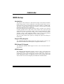
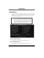
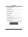
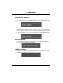
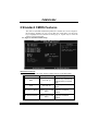
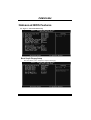
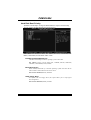
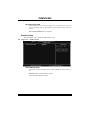
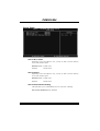
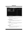
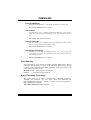
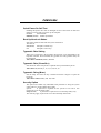
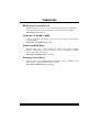
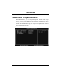
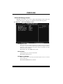
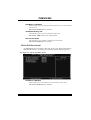
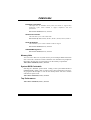
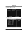
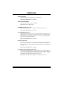
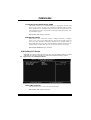
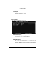
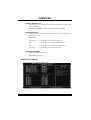
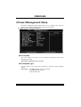
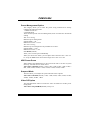
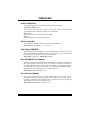
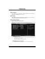
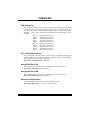
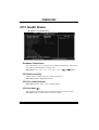
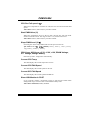
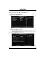
P4M900-M4 BIOS Setup BIOS Setup ................................................................................................ 1 1 Main Menu ............................................................................................. 3 2 Standard CMOS Features..................................................................... 7 3Advanced BIOS Features ....................................................................... 9 4 Advanced Chipset Features................................................................. 17 5 Integrated Peripherals......................................................................... 21 6 Power Management Setup................................................................... 27 7 PnP/PCI Configurations...................................................................... 32 8 PC Health Status .................................................................................. 35 9 Performance Booster Zone.................................................................. 37 i P4M900-M4 BIOS Setup Introduction The purpose of this manual is to describe the settings in the Pheonix-Award™ BIOS Setup program on this motherboard. The Setup program allows users to modify the basic system configuration and save these settings to CMOS RAM. The power of CMOS RAM is supplied by a battery so that it retains the Setup information when the power is turned off. Basic Input-Output System (BIOS) determines what a computer can do without accessing programs from a disk. This system controls most of the input and output devices such as keyboard, mouse, serial ports and disk drives. BIOS activates at the first stage of the booting process, loading and executing the operating system. Some additional features, such as virus and password protection or chipset fine-tuning options are also included in BIOS. The rest of this manual will to guide you through the options and settings in BIOS Setup. Plug and Play Support This PHEONIX-AWARD BIOS supports the Plug and Play Version 1.0A specification and ESCD (Extended System Configuration Data) write. EPA Green PC Support This PHEONIX-AWARD BIOS supports Version 1.03 of the EPA Green PC specification. APM Support This PHEONIX-AWARD BIOS supports Version 1.1&1.2 of the Advanced Power Management (APM) specification. Power management features are implemented via the System Management Interrupt (SMI). Sleep and Suspend power management modes are supported. Power to the hard disk drives and video monitors can also be managed by this PHEONIX-AWARD BIOS. 1 P4M900-M4 ACPI Support Pheonix-Award ACPI BIOS support Version 1.0b of Advanced Configuration and Power interface specification (ACPI). It provides ASL code for power management and device configuration capabilities as defined in the ACPI specification, developed by Microsoft, Intel and Toshiba. PCI Bus Support This PHEONIX-AWARD BIOS also supports Version 3.0 of the Intel PCI (Peripheral Component Interconnect) local bus specification. DRAM Support DDR SDRAM (Double Data Rate Synchronous DRAM) is supported. Supported CPUs This PHEONIX-AWARD BIOS supports the Intel CPU. Using Setup Use the arrow keys to highlight items in most of the place, press <Enter> to select, use the <PgUp> and <PgDn> keys to change entries, press <F1> for help and press <Esc> to quit. The following table provides more detail about how to navigate in the Setup program by using the keyboard. Keystroke Up arrow Down arrow Left arrow Right arrow Move Enter PgUp key PgDn key + Key - Key Esc key F1 key F5 key F7 key F10 key Function Move to previous item Move to next item Move to the item on the left (menu bar) Move to the item on the right (menu bar) Move to the item you desired Increase the numeric value or make changes Decrease the numeric value or make changes Increase the numeric value or make changes Decrease the numeric value or make changes Main Menu – Quit and not save changes into CMOS Status Page Setup Menu and Option Page Setup Menu – E xit Current page and return to Main Menu General help on Setup navigation keys Load previous values from CMOS Load the optimized defaults Save all the CMOS changes and exit 2 P4M900-M4 1 Main Menu Once you enter Pheonix-Award BIOS™ CMOS Setup Utility, the Main Menu will appear on the screen. The Main Menu allows you to select from several setup functions. Use the arrow keys to select among the items and press <Enter> to accept and enter the sub-menu. !! WARNING !! For better system performance, the BIOS firmware is being continuously updated. The BIOS information described in this manual (Figure 1, 2, 3, 4, 5, 6, 7, 8, 9) is for your reference only. The actual BIOS information and settings on board may be slightly different from this manual. Figure 1: Main Menu Standard CMOS Features This submenu contains industry standard configurable options. Advanced BIOS Features This submenu allows you to configure advanced features of the BIOS. 3 P4M900-M4 Advanced Chipset Features This submenu allows you to configure special chipset features. Integrated Peripherals This submenu allows you to configure certain IDE hard drive options and Programmed Input/ Output features. Power Management Setup This submenu allows you to configure the power management features. PnP/PCI Configurations This submenu allows you to configure certain “Plug and Play” and PCI options. PC Health Status This submenu allows you to monitor the hardware of your system. Performance Booster Zone This submenu allows you to change CPU Vcore Voltage and CPU/PCI clock. (However, we suggest you to use the default setting. Changing the voltage and clock improperly may damage the CPU or M/B!) Load Optimized Defaults This selection allows you to reload the BIOS when problem occurs during system booting sequence. These configurations are factory settings optimized for this system. A confirmation message will be displayed before defaults are set. 4 P4M900-M4 Set Supervisor Password Setting the supervisor password will prohibit everyone except the supervisor from making changes using the CMOS Setup Utility. You will be prompted with to enter a password. Set User Password If the Supervisor Password is not set, then the User Password will function in the same way as the Supervisor Password. If the Supervisor Password is set and the User Password is set, the “User” will only be able to view configurations but will not be able to change them. Save & Exit Setup Save all configuration changes to CMOS (memory) and exit setup. Confirmation message will be displayed before proceeding. Exit Without Saving Abandon all changes made during the current session and exit setup. Confirmation message will be displayed before proceeding. 5 P4M900-M4 Upgrade BIOS This submenu allows you to upgrade bios. 6 P4M900-M4 2 Standard CMOS Features The items in Standard CMOS Setup Menu are divided into several categories. Each category includes no, one or more than one setup items. Use the arrow keys to highlight the item and then use the<PgUp> or <PgDn> keys to select the value you want in each item. Figure 2: Standard CMOS Setup Main Menu Selections This table shows the items and the available options on the Main Menu. Item Options Description Date mm : dd : yy Set the system date. Note that the ‘Day’ automatically changes when you set the date. Time hh : mm : ss Set the system internal clock. IDE Channel 0 Master Options are in its sub menu. Press <Enter> to enter the sub menu of detailed options IDE Channel 0 Slave Options are in its sub menu. Press <Enter> to enter the sub menu of detailed options. 7 P4M900-M4 Item Options Description IDE Channel 1 Master Options are in its sub menu. Press <Enter> to enter the sub menu of detailed options. IDE Channel 1 Slave Options are in its sub menu. Press <Enter> to enter the sub menu of detailed options. 360K, 5.25 in 1.2M, 5.25 in Drive A 720K, 3.5 in Drive B 1.44M, 3.5 in Select the type of floppy disk drive installed in your system. 2.88M, 3.5 in None All Errors No Errors Halt On All, but Keyboard All, but Diskette Select the situation in which you want the BIOS to stop the POST process and notify you. All, but Disk/ Key Base Memory N/A Displays the amount of conventional memory detected during boot up. Extended Memory N/A Displays the amount of extended memory detected during boot up. Total Memory N/A Displays the total memory available in the system. 8 P4M900-M4 3Advanced BIOS Features Figure 3: Advanced BIOS Setup Boot Seq & Floppy Setup This item allows you to setup boot sequence & Floppy. 9 P4M900-M4 Hard Disk Boot Priority The BIOS will attempt to arrange the Hard Disk boot sequence automatically. You can change the Hard Disk booting sequence here. The Choices: Pri. Master, Pri. Slave, Sec. Master, Sec. Slave, USB HDD0, USB HDD1, USB HDD2, and Bootable Add-in Cards. First/Second/Third Boot Device The BIOS will attempt to load the operating system in this order. The Choices: Floppy, LS120, Hard Disk, CDROM, ZIP100, USB-FDD, USB-ZIP, USB-CDROM, LAN, Disabled. Boot Other Device When enabled, BIOS will try to load the operating system from other device when it failed to load from the three devices above. The Choices: Enabled (default), Disabled Swap Floppy Drive For systems with two floppy drives, this option allows you to swap logical drive assignments. The Choices: Disabled (default), Enabled. 10 P4M900-M4 Boot Up Floppy Seek When enabled, System will test the floppy drives to determine if they have 40 or 80 tracks during boot up. Disabling this option reduces the time it takes to boot-up. The Choices: Enabled (default), Disabled. Shadow Setup This item allows you to setup cache & shadow setup. Figure 3.2: Shadow Setup Video BIOS Shadow Determines whether video BIOS will be copied to RAM for faster execution or not. Enabled (default) Optional ROM is enabled. Disabled Optional ROM is disabled. 11 P4M900-M4 Cache Setup CPU L1 & L2 Cache Depending on the CPU/chipset in use, you may be able to increase memory access time with this option. Enabled (default) Enable cache. Disabled Disable cache. CPU L3 Cache Depending on the CPU/chipset in use, you may be able to increase memory access time with this option. Enabled (default) Enable cache. Disabled Disable cache. CPU L2 Cache ECC Checking This item allows you to enable/disable CPU L2 Cache ECC Checking. The Choices: Enabled (default), Disabled. 12 P4M900-M4 CPU Feature Delay Prior to Thermal Set this item to enable the CPU Thermal function to engage after the specified time. The Choices: 4 Min, 8 Min, 16Min (default), 32 Min. Thermal Management This option allows you to select the way to control the “Thermal Management.” The Choices: Thermal Monitor 1 (default), Thermal Monitor 2. TM2 Bus Ratio This option represents the frequency (bus ratio) of the throttled performance state that will be initiated when the on-die sensor detects temperature increase. Min= 0 Max= 255 Key in a DEC number. The Choices: 0 X (default) TM2 Bus VID This option represents the voltage of the throttled performance state that will be initiated when the on-die sensor detects temperature increase. The Choices: 0.8375V (default), 0.8375-1.6000. 13 P4M900-M4 Limit CPUID MaxVal Set Limit CPUID MaxVal to 3, it should be “Disabled” for Windows XP. The Choices: Disabled (default), Enabled. C1E Function This item allows you to configure the Enhanced Halt State (C1E) function, which may reduce the power consumption of your system when the system is idle. The Choices: Auto (default),Disabled. Execute Disable Bit This item allows you to configure the Execute Disabled Bit function, which protects your system from buffer overflow attacks. The Choices: Enabled (default), Disabled. Virtualization Technology Virtualization Technology can virtually separate your system resource into several parts, thus enhance the performance when running virtual machines or multi interface systems. The Choices: Enabled (default), Disabled. Virus Warning This option allows you to choose the VIRUS Warning feature that is used to protect the IDE Hard Disk boot sector. If this function is enabled and an attempt is made to write to the boot sector, BIOS will display a warning message on the screen and sound an alarm beep. Disabled (default) Virus protection is disabled. Enabled Virus protection is activated. Hyper-Threading Technology This option allows you to enable or disabled Hyper-Threading Technology. “Enabled” for Windows XP and Linux 2.4.x (OS optimized for Hyper-Threading Technology). “Disable” for other OS (OS not optimized for Hyper-Threading Technology). The Choices: Enabled (default), Disabled. 14 P4M900-M4 Quick Power On Self Test Enabling this option will cause an abridged version of the Power On Self-Test (POST) to execute after you power up the computer. Disabled Normal POST. Enabled (default) Enable quick POST. Boot Up NumLock Status Selects the NumLock State after the system switched on. The Choices: On (default) Numpad is number keys. Off Numpad is arrow keys. Typematic Rate Setting When a key is held down, the keystroke will repeat at a rate determined by the keyboard controller. When enabled, the typematic rate and typematic delay can be configured. The Choices: Disabled (default), Enabled. Typematic Rate (Chars/Sec) Sets the rate at which a keystroke is repeated when you hold the key down. The Choices: 6 (default), 8, 10, 12, 15, 20, 24, 30. Typematic Delay (Msec) Sets the delay time after the key is held down before it begins to repeat the keystroke. The Choices: 250 (default), 500, 750, 1000. Security Option This option will enable only individuals with passwords to bring the system online and/or to use the CMOS Setup Utility. System: A password is required for the system to boot and is also required to access the Setup Utility. Setup (default): A password is required to access the Setup Utility only. This will only apply if passwords are set from the Setup main menu. 15 P4M900-M4 MPS Version Control For OS The BIOS supports version 1.1 and 1.4 of the Intel multiprocessor specification. Select version supported by the operation system running on this computer. The Choices: 1.4 (default), 1.1. OS Select For DRAM > 64MB A choice other than Non-OS2 is only used for OS2 systems with memory exceeding 64MB. The Choices: Non-OS2 (default), OS2. Small Logo(EPA) Show This item allows you to select whether the “Small Logo” shows. Enabled (default) “Small Logo” shows when system boots up. Disabled No “Small Logo” shows when system boots The Choices: Enabled (default), Disabled Summary Screen Show This item allows you to enable/disable the summary screen. Summary screen means system configuration and PCI device listing. The Choices: Disabled (default), Enabled. 16 P4M900-M4 4 Advanced Chipset Features This submenu allows you to configure the specific features of the chipset installed on your system. This chipset manage bus speeds and access to system memory resources, such as DRAM. It also coordinates communications with the PCI bus. The default settings that came with your system have been optimized and therefore should not be changed unless you are suspicious that the settings have been changed incorrectly. Figure 4: Advanced Chipset Setup 17 P4M900-M4 AGP & P2P Bridge Control Highlight “Press Enter” next to the “AGP & P2P Bridge Control” label and pressing the enter key will take you a submenu with the following options: Figure 4.1: AGP & P2P Bridge Control AGP Aperture Size Select the size of the Accelerated Graphics Port (AGP) aperture. The aperture is a portion of the PCI memory address range dedicated for graphics memory address space. Host cycles that hit the aperture range are forwarded to the AGP without the need of translation. The Choices: 32M, 64M, 128M (default), 256M. AGP 2.0 Mode This item allows you to select the AGP Mode. The Choices: 4X (default), 8X. AGP Master 1 WS Write When enabled, writes to the AGP (Accelerated Graphics Port) are executed with one wait states. The Choices: Enabled (default), Disabled. 18 P4M900-M4 AGP Master 1 WS Read When enabled, read to the AGP (Accelerated Graphics Port) are executed with one wait states. The Choices: Enabled (default), Disabled. VGA Share Memory Size This item allows you to select the VGA share memory size. The Choices: 128M (default), 64M, 256M, Disabled Direct Frame Buffer This item allows you to disabled or enabled direct frame buffer The Choices: Enabled (default), Disabled. CPU & PCI Bus Control By highlighting the “Press Enter” label next to the “CPU & PCI Bus Control” and press the enter key, it will take you a submenu with the following options: Figure 4.2: CPU & PCI Bus Control PCI Master 0 WS Write When enabled, writes to the PCI bus are executed with zero-wait states. The Choices: Enabled (default), Disabled. 19 P4M900-M4 PCI Delay Transaction The chipset has an embedded 32-bit posted write buffer to support delay transactions cycles. Select Enabled to support compliance with PCI specification. The Choices: Enabled (default), Disabled. Vlink mode selection This item allows you to select Vlink mode. The Choices: By Auto (default), Mode 0 , Mode 1, Mode 2, Mode 3, Mode 4. VLink 8X Support This item allows you to enable or disable VLink 8X support. The Choices: Enabled (default), Disabled. VIA PWR Management The Choices: Enabled (default), Disabled. Memory Hole You can reserve this area of system memory for ISA adapter ROM. When this area is reserved it cannot be cached. Check the user information of peripherals that need to use this area of system memory for the memory requirements. The Choices: Disabled (default), Enabled. System BIOS Cacheable Selecting the “Enabled” option allows caching of the system BIOS ROM at F0000h-FFFFFh, which is able to improve the system performance. However, any programs that attempts to write to this memory block will cause conflicts and result in system errors. The Choices: Enabled (default), Disabled. Top Performance The Choices: Disabled (default), Enabled. 20 P4M900-M4 5 Integrated Peripherals Figure 5. Integrated Peripherals VIA OnChip IDE Device Highlight the “Press Enter” label next to the “VIA OnChip IDE Device” label and press enter key will take you a submenu with the following options: 21 P4M900-M4 SATA Controller This option allows you to enable the on-chip Serial ATA. The Choices: Enabled (default), Disabled. SATA Controller Mode This option allows you to select SATA Mode. The Choices: RAID, IDE (default). IDE DMA Transfer Access This item allows you to enable or disable the IDE DMA transfer access. The Choices: Enabled (default), Disabled. On-chip IDE Channel 0/1 The motherboard chipset contains a PCI IDE interface with support for two IDE channels. Select “Enabled” to activate the first and/or second IDE interface. Select “Disabled” to deactivate an interface if you are going to install a primary and/or secondary add-in IDE interface. The Choices: Enabled (default), Disabled. IDE Prefetch Mode The “onboard” IDE drive interfaces supports IDE prefetch function for faster drive access. If the interface on your drive does not support prefetching, or if you install a primary and/or secondary add-in IDE interface, set this option to “Disabled”. The Choices: Enabled (default), Disabled. Primary/Secondary Master/Slave PIO The IDE PIO (Programmed Input / Output) fields let you set a PIO mode (0-4) for each of the IDE devices that the onboard IDE interface supports. Modes 0 to 4 will increase performance progressively. In Auto mode, the system automatically determines the best mode for each device. The Choices: Auto (default), Mode0, Mode1, Mode2, Mode3, Mode4. 22 P4M900-M4 Primary/Secondary Master/Slave UDMA Ultra DMA function can be implemented if it is supported by the IDE hard drives in your system. As well, your operating environment requires a DMA driver (Windows 95 or OSR2may need a third party IDE bus master driver). If your hard drive and your system software both support Ultra DMA, select Auto to enable BIOS support. The Choices: Auto (default), Disabled. IDE HDD Block Mode Block mode is also called block transfer, multiple commands, or multiple sectors read / write. If your IDE hard drive supports block mode (most new drives do), select Enabled for automatic detection of the optimal number of block mode (most new drives do), select Enabled for automatic detection of the optimal number of block read / write per sector where the drive can support. The Choices: Enabled (default), Disabled. VIA OnChip PCI Device Highlight the “Press Enter” label next to the “VIA OnChip PCI Device” label and press the enter key will take you a submenu with the following options: Figure 5.2: VIA OnChip PCI Device Azalia HDA Controller This option allows you to control the onboard HD audio. The Choices: Auto (default), Disabled. 23 P4M900-M4 LAN Controller This option allows you to control the onboard LAN. The Choices: Enabled (default), Disabled Lan Boot ROM Decide whether to invoke the boot ROM of the onboard LAN chip. The Choices: Disable (default), Enabled. Super IO Device Press Enter to configure the Super I/O Device. Onboard FDC Controller Select enabled if your system has a floppy disk controller (FDC) installed on the system board and you wish to use it. If you installed another FDC or the system uses no floppy drive, select disabled in this field. The Choices: Enabled (default), Disabled. Onboard Serial Port 1 Select an address and corresponding interrupt for the first and second serial ports. The Choices: 3F8/IRQ4 (default), Disabled, 2F8/IRQ3, 3E8/IRQ4, 2E8/IRQ3, Auto. 24 P4M900-M4 Onboard Parallel Port This item allows you to determine access onboard parallel port controller with which I/O Address. The Choices: 378/IRQ7 (default), 278/IRQ5, 3BC/IRQ7, Disabled. Parallel Port Mode This item allows you to determine how the parallel port should function. The default value is SPP. The Choices: SPP (default) Using Parallel port as Standard Printer Port. EPP Using Parallel Port as Enhanced Parallel Port. ECP Using Parallel port as Extended Capabilities Port. ECP+EPP Using Parallel port as ECP & EPP mode. ECP Mode Use DMA Select a DMA Channel for the port. The Choices: 3 (default), 1. USB Device Setting Press Enter to configure the USB Device. 25 P4M900-M4 USB 1.0/2.0 Controller These options allow you to enable or disable the USB 1.0/2.0 controller function. The Choices: Enabled (default), Disabled. USB Operation Mode This option let you select the operation mode of USB function. The Choices: High Speed (default), Full/Low Speed. USB Keyboard/Mouse/Storage Function These options allow you to enable or disable the USB keyboard/mouse/storage devices. The Choices: Enabled (default), Disabled. USB Mass Storage Device Boot Setting These options allow you to choose the boot up type of the USB mass storage devices.. The Choices: Auto mode (default), FDD mode, HDD mode. 26 P4M900-M4 6 Power Management Setup The Power Management Setup Menu allows you to configure your system to utilize energy conservation and power up/power down features. Figure 6. Power Management Setup ACPI Function This item displays the status of the Advanced Configuration and Power Management (ACPI). The Choices: Enabled (default), Disabled. ACPI Suspend Type The item allows you to select the suspend type under the ACPI operating system. The Choices: S1 (POS) (default) Power on Suspend S3 (STR) Suspend to RAM S1 & S3 POS+STR 27 P4M900-M4 Power Management Option This category allows you to select the power saving method and is directly related to the following modes: 1. HDD Power Down. 2. Suspend Mode. There are three options of Power Management, three of which have fixed mode settings Min. Power Saving Minimum power management. Suspend Mode = 1 hr. HDD Power Down = 15 min Max. Power Saving Maximum power management only available for sl CPU’s. Suspend Mode = 1 min. HDD Power Down = 1 min. User Define (default) Allow you to set each option individually. When you choose user define, you can adjust each of the item from 1 min. to 1 hr. except for HDD Power Down which ranges from 1 min. to 15 min. HDD Power Down When enabled, the hard-disk drives will power down after a set time of system inactivity. All other devices remain active. The Choices: Disabled (default), 1 Min, 2 Min, 3 Min, 4 Min, 5 Min, 6 Min, 7 Min, 8 Min, 9 Min, 10 Min, 11 Min, 12 Min, 13 Min, 14 Min, 15Min. Suspend Mode The item allows you to adjust the system idle time before suspend. The Choices: Disabled (default), 1 Min, 2 Min, 4 Min, 6 Min, 8 Min, 10 Min, 20 Min, 30 Min, 40 Min, 1 Hour. Video Off Option This field determines when to activate the video off feature for monitor power management. The Choices: Suspend→Off (default), Always on. 28 P4M900-M4 Video Off Method This option determines the manner when the monitor goes blank. V/H SYNC+Blank (default) This selection will cause the system to turn off the vertical and horizontal synchronization ports and write blanks to the video buffer. Blank Screen This option only writes blanks to the video buffer. DPMS Initial display power management signaling. Modem Use IRQ This determines the IRQ, which can be applied in MODEM use. The Choices: 3 (default), 4, 5, 7, 9, 10, 11, NA. Soft-Off by PWRBTN This item determines the behavior of system power button. Instant off turn off the power immediately, and Delay 4 Sec. will require you to press and hold the power button for 4 seconds to cut off the system power. The Choices: Delay 4 Sec, Instant-Off (default). Run VGABIOS if S3 Resume Choosing Enabled will make BIOS run VGA BIOS to initialize the VGA card when system wakes up from S3 state. The system resume time is shortened if you disable the function, but system will need AGP driver to initialize the card. So, if the AGP driver of the VGA card does not support the initialization feature, the display may work abnormally or not function after S3. The Choices: Auto (default), Yes, No. Ac Loss Auto Restart This setting specifies how your system should behave after a power fail or interrupts occurs. By choosing off will leave the computer in the power off state. Choosing On will reboot the computer. Former-Sts will restore the system to the status before power failure or interrupt occurs. The Choices: Off (default), On, Former-Sts. 29 P4M900-M4 HPET Support This option allows you to disabled or enables the High Precision Event Timer. The Choices: Enabled (default), Disabled. HPET Mode This option allows you to select the modes of the High Precision Event Timer. The Choices: 32-bit mode (default), 64-bit mode. Wakeup Event Detect Figure 6.1:IRQ/Event Activity Detect Highlight the “Press Enter” label next to the “Wakeup Event Detect” label and press the enter key will take you a submenu with the following options: PS2KB Wakeup Select When select Password, please press Enter key to change password with a maximum length of 8 characters. The Choices: Hot Key (default), Password. PS2KB Wakeup from S3/ S4/ S5 This item allows you to wake up from S3/ S4/ S5 with PS2 keyboard. 30 P4M900-M4 The Choices: Disabled (default), Ctrl+F1, Ctrl+F2. Ctrl+F3, Ctrl+F4, Ctrl+F5, Ctrl+F6, Ctrl+F7, Ctrl+F8, Ctrl+F9, Ctrl+F10, Ctrl+F11, Ctrl+F12, Power, Wake, Any Key. PS2MS Wakeup from S3/ S4/ S5 This item allows you to wake up from S3/ S4/ S5 with PS2 mouse. The Choices: Disabled (default), Enabled. USB Resume from S3 This item allows you to wake up from S3 with USB device. The Choices: Disabled (default), Enabled. PowerOn by PCI Card When you select Enabled, a PME signal from PCI card returns the system to Full ON state. For this function to work, you may need a LAN add-on card which supports the Wake on LAN function. Set the Wake on LAN (WOL) jumper on motherboard to enable if applicable. The Choices: Disabled (default), Enabled. Modem Ring Resume This item allows you to disable or enable Modem Ring Resume function. The Choices: Disabled (default), Enabled. RTC Alarm Resume When “Enabled”, you can set the date and time at which the RTC (real-time clock) alarm awakens the system from Suspend mode. The Choices: Disabled (default), Enabled. Date (of Month) You can choose which month the system will boot up. This field is only configurable when “RTC Resume” is set to “Enabled”. Resume Time (hh:mm:ss) You can choose the hour, minute and second the system will boot up. This field is only configurable when “RTC Resume” is set to “Enabled”. 31 P4M900-M4 7 PnP/PCI Configurations This section describes configuring the PCI bus system. PCI, or Personal Computer Interconnect, is a system which allows I/O devices to operate at speeds nearing the speed of the CPU itself uses when communicating with its own special components. This section covers some very technical items and it is strongly recommended that only experienced users should make any changes to the default settings. Figure 7: PnP/PCI Configurations PNP OS Installed When set to YES, BIOS will only initialize the PnP cards used for the boot sequence (VGA, IDE, SCSI). The rest of the cards will be initialized by the PnP operating system like Window™ 95. When set to NO, BIOS will initialize all the PnP cards. For non-PnP operating systems (DOS, Netware™), this option must set to NO. The Choices: No (default), Yes. 32 P4M900-M4 Init Display First This item allows you to decide to active whether PCI Slot or on-chip VGA first. The Choices: PCIEx(default), PCI Slot, Onboard, AGP. Reset Configuration Data The system BIOS supports the PnP feature which requires the system to record which resources are assigned and protects resources from conflict. Every peripheral device has a node, which is called ESCD. This node records which resources are assigned to it. The system needs to record and update ESCD to the memory locations. These locations are reserved in the system BIOS. If the Disabled (default) option is chosen, the system‘s ESCD will update only when the new configuration varies from the last one. If the Enabled option is chosen, the system is forced to update ESCDs and then is automatically set to the “Disabled” mode. The above settings will be shown on the screen only if “Manual” is chosen for the resources controlled by function. Legacy is the term, which signifies that a resource is assigned to the ISA Bus and provides non-PnP ISA add-on cards. PCI / ISA PnP signify that a resource is assigned to the PCI Bus or provides for ISA PnP add-on cards and peripherals. The Choices: Disabled (default), Enabled. Resources Controlled By By Choosing “Auto(ESCD)” (default), the system BIOS will detect the system resources and automatically assign the relative IRQ and DMA channel for each peripheral. By Choosing “Manual”, the user will need to assign IRQ & DMA for add-on cards. Be sure that there are no IRQ/DMA and I/O port conflicts. The Choices: Auto (ESCD) (default), Manual. 33 P4M900-M4 IRQ Resources This submenu will allow you to assign each system interrupt a type, depending on the type of device using the interrupt. When you press the “Press Enter” tag, you will be directed to a submenu that will allow you to configure the system interrupts. This is only configurable when “Resources Controlled By” is set to “Manual”. IRQ-3 assigned to PCI Device IRQ-4 assigned to PCI Device IRQ-5 assigned to PCI Device IRQ-7 assigned to PCI Device IRQ-9 assigned to PCI Device IRQ-10 assigned to PCI Device IRQ-11 assigned to PCI Device IRQ-12 assigned to PCI Device IRQ-14 assigned to PCI Device IRQ-15 assigned to PCI Device PCI / VGA Palette Snoop Some old graphic controllers need to “snoop” on the VGA palette and then map it to their display as a way to provide boot information and VGA compatibility. This item allows such snooping to take place. The Choices: Disabled (default), Enabled Assign IRQ For VGA This item allows the users to choose which IRQ to assign for the VGA. The Choices: Enabled (default), Disabled. Assign IRQ For USB This item allows the users to choose which IRQ to assign for the USB. The Choices: Enabled (default), Disabled. Maximum Payload Size Set the maximum payload size for Transaction packets (TLP). The Choice: 4096 (default.), 128, 256, 512, 1024, 2048. 34 P4M900-M4 8 PC Health Status Figure 8: PC Health Status Shutdown Temperature This item allows you to set up the CPU shutdown Temperature. This item is only effective under Windows 98 ACPI mode. The Choices: 70℃/ 158℉, 75℃/ 167℉, 80℃/ 176℉, 85℃/ 185℉ (default). CPU FAN Control by Choose “smart” to reduce the noise caused by CPU FAN. The Choices: Smart, Always On (default). CPU Fan Load (Sharp=0) The Choices: Min=0, Max=7; key in a DEC number. CPU Fan Start (℃) CPU fan starts to work under smart fan function when arrive this set value. The Choices: Min=0, Max=100; key in a DEC number. 35 P4M900-M4 CPU Fan Full speed <℃> When CPU temperature is reach the set value, the CPU fan will work under Full Speed. The Choices: Min=0, Max=100; key in a DEC number. Start PWM Value (%) When CPU temperature arrives to the set value, the CPU fan will work under Smart Fan Function mode. The range is from 0~127, with an interval of 1. The Choices: Min=0, Max=100; key in a DEC number. Slope PWM Level (%/℃) Increasing the value of slope PWM will raise the speed of CPU fan. The Choices: 3.1%/℃ Medium(default), 0.0%/℃, 0.8%/℃, 1.6%/℃,6.3%/℃ High,12.5%/℃, 25.0%/℃, 50.0%/℃. CPU Vcore, NB Vcore, +3.3V, +5.0V, +12V, DRAM Voltage, VTT Voltage, Voltage Battery Detect the system’s voltage status automatically. Current CPU Temp This field displays the current temperature of CPU. Current CPU FAN Speed This field displays the current speed of CPU fan. Current SYS FAN Speed This field displays the current speed SYSTEM fan. Show H/W Monitor in POST If you computer contains a monitoring system, it will show PC health status during POST stage. The item offers several different delay times. The Choices: Enabled (default), Disabled. 36 P4M900-M4 9 Performance Booster Zone Figure 9: Performance Booster Zone DRAM Clock/Drive Control This item controls the DRAM Clock. Highlight “Press Enter” next to the “DRAM Clock/Drive Control” label and pressing the enter key will take you a submenu with the following options: Figure 9.1: DRAM Clock/Drive Control 37 P4M900-M4 DRAM Clock This item determines DRAM clock. The Choices: By SPD (default), 100MHz, 133MHz, 166MHz, 200MHz, 266MHz, 333MHz . DRAM Timing This item determines DRAM clock/ timing. The Choices: Auto by SPD (default), Manual, Turbo, Ultra. SDRAM CAS Latency When DRAM is installed, the number of clock cycles of CAS latency depends on the DRAM timing. The Choices: 2.5 /4(default). Bank Interleave This item allows you to enable or disable the bank interleave feature. The Choices: Disabled (default). Precharge to Active (tRP) This item allows you to specify the delay from precharge command to activate command. The Choices: 4T (default). Active to Precharge (tRAS) This item allows you to specify the minimum row active time (tRAS). The Choices: 07T (default). Active to CMD (tRCD) Use this item to specify the delay from the activation of a bank to the time that a read or write command is accepted. The Choices: 4T (default). REF to ACT/REF to REF (Trfc) This item allows you to determine the selection for REF to ACT/REF to REF (tRFC). The Choices: 20T/21T (default). 38 P4M900-M4 ACT (0) to ACT (1) (tRRD) This item allows you to determine the selection for ACT (0) to ACT (1) (tRRD) The Choices: 3T (default). 1T CMD Support The Choices: Disable (default), Auto. DDR2 On Die Termination This option allows you to choose the working type of ODT. The Choices: ODT Always ON (default), Dynamic ODT, ODT Always OFF. CPU CLOCK This item allows you to select CPU Clock, and CPU over clocking. Special Notice: If the system’s frequency that you are selected is not functioning, there are two methods of booting-up the system. Method 1: Clear the COMS data by setting the JCOMS1 ((2-3) closed)) as “ON” status. All the CMOS data will be loaded as defaults setting. Method 2: Press the <Insert> key and Power button simultaneously, after that keep-on pressing the <Insert> key until the power-on screen showed. This action will boot-up the system according to FSB of the processor It’s strongly recommended to set CPU Vcore and clock in default setting. If the CPU Vcore and clock are not in default setting, it may cause CPU or M/B damage. The Choices: 100MHz(default); Min=100, Max=400, key in a DEC number. Async PCIE CLOCK This item allows you to select Async PCIE clock. Min= 100 Max=150 Key in a DEC number. The Choices: 100MHz(default) ; Min=100, Max=150, key in a DEC number. CPU Clock Ratio This item allows you to select the CPU Ratio. Min= 6 Max= 50 Key in a DEC number. The Choices: 6X (default). 39 P4M900-M4 Spread Spectrum This item allows you to enable/disable the Spread Spectrum function. The Choices:+/- 0.25% (default), +/- 0. 5%, Disabled, -0.5%, -1.0%. DDR Voltage This item allows you to select DDR Voltage. The Choices: StartUp (default), +0.10V, +0.20V, +0.30V, +0.40V, +0.50V, +0.60V, +0.70V. CPU Voltage This item allows you to select CPU Voltage. The Choices: StartUp (default), +0.012V~+0.787V. 40